EP3021985B1 - Sprayer - Google Patents
Sprayer Download PDFInfo
- Publication number
- EP3021985B1 EP3021985B1 EP14752435.9A EP14752435A EP3021985B1 EP 3021985 B1 EP3021985 B1 EP 3021985B1 EP 14752435 A EP14752435 A EP 14752435A EP 3021985 B1 EP3021985 B1 EP 3021985B1
- Authority
- EP
- European Patent Office
- Prior art keywords
- sprayer
- housing
- fluid
- bridge
- outlet
- Prior art date
- Legal status (The legal status is an assumption and is not a legal conclusion. Google has not performed a legal analysis and makes no representation as to the accuracy of the status listed.)
- Not-in-force
Links
Images







Classifications
-
- B—PERFORMING OPERATIONS; TRANSPORTING
- B05—SPRAYING OR ATOMISING IN GENERAL; APPLYING FLUENT MATERIALS TO SURFACES, IN GENERAL
- B05B—SPRAYING APPARATUS; ATOMISING APPARATUS; NOZZLES
- B05B1/00—Nozzles, spray heads or other outlets, with or without auxiliary devices such as valves, heating means
- B05B1/30—Nozzles, spray heads or other outlets, with or without auxiliary devices such as valves, heating means designed to control volume of flow, e.g. with adjustable passages
- B05B1/3033—Nozzles, spray heads or other outlets, with or without auxiliary devices such as valves, heating means designed to control volume of flow, e.g. with adjustable passages the control being effected by relative coaxial longitudinal movement of the controlling element and the spray head
- B05B1/308—Nozzles, spray heads or other outlets, with or without auxiliary devices such as valves, heating means designed to control volume of flow, e.g. with adjustable passages the control being effected by relative coaxial longitudinal movement of the controlling element and the spray head the controlling element comprising both a lift valve and a deflector separated from the lift valve
-
- B—PERFORMING OPERATIONS; TRANSPORTING
- B05—SPRAYING OR ATOMISING IN GENERAL; APPLYING FLUENT MATERIALS TO SURFACES, IN GENERAL
- B05B—SPRAYING APPARATUS; ATOMISING APPARATUS; NOZZLES
- B05B3/00—Spraying or sprinkling apparatus with moving outlet elements or moving deflecting elements
- B05B3/02—Spraying or sprinkling apparatus with moving outlet elements or moving deflecting elements with rotating elements
- B05B3/04—Spraying or sprinkling apparatus with moving outlet elements or moving deflecting elements with rotating elements driven by the liquid or other fluent material discharged, e.g. the liquid actuating a motor before passing to the outlet
-
- B—PERFORMING OPERATIONS; TRANSPORTING
- B05—SPRAYING OR ATOMISING IN GENERAL; APPLYING FLUENT MATERIALS TO SURFACES, IN GENERAL
- B05B—SPRAYING APPARATUS; ATOMISING APPARATUS; NOZZLES
- B05B1/00—Nozzles, spray heads or other outlets, with or without auxiliary devices such as valves, heating means
- B05B1/26—Nozzles, spray heads or other outlets, with or without auxiliary devices such as valves, heating means with means for mechanically breaking-up or deflecting the jet after discharge, e.g. with fixed deflectors; Breaking-up the discharged liquid or other fluent material by impinging jets
- B05B1/262—Nozzles, spray heads or other outlets, with or without auxiliary devices such as valves, heating means with means for mechanically breaking-up or deflecting the jet after discharge, e.g. with fixed deflectors; Breaking-up the discharged liquid or other fluent material by impinging jets with fixed deflectors
- B05B1/267—Nozzles, spray heads or other outlets, with or without auxiliary devices such as valves, heating means with means for mechanically breaking-up or deflecting the jet after discharge, e.g. with fixed deflectors; Breaking-up the discharged liquid or other fluent material by impinging jets with fixed deflectors the liquid or other fluent material being deflected in determined directions
-
- B—PERFORMING OPERATIONS; TRANSPORTING
- B05—SPRAYING OR ATOMISING IN GENERAL; APPLYING FLUENT MATERIALS TO SURFACES, IN GENERAL
- B05B—SPRAYING APPARATUS; ATOMISING APPARATUS; NOZZLES
- B05B1/00—Nozzles, spray heads or other outlets, with or without auxiliary devices such as valves, heating means
- B05B1/30—Nozzles, spray heads or other outlets, with or without auxiliary devices such as valves, heating means designed to control volume of flow, e.g. with adjustable passages
- B05B1/3006—Nozzles, spray heads or other outlets, with or without auxiliary devices such as valves, heating means designed to control volume of flow, e.g. with adjustable passages the controlling element being actuated by the pressure of the fluid to be sprayed
-
- B—PERFORMING OPERATIONS; TRANSPORTING
- B05—SPRAYING OR ATOMISING IN GENERAL; APPLYING FLUENT MATERIALS TO SURFACES, IN GENERAL
- B05B—SPRAYING APPARATUS; ATOMISING APPARATUS; NOZZLES
- B05B1/00—Nozzles, spray heads or other outlets, with or without auxiliary devices such as valves, heating means
- B05B1/30—Nozzles, spray heads or other outlets, with or without auxiliary devices such as valves, heating means designed to control volume of flow, e.g. with adjustable passages
- B05B1/32—Nozzles, spray heads or other outlets, with or without auxiliary devices such as valves, heating means designed to control volume of flow, e.g. with adjustable passages in which a valve member forms part of the outlet opening
- B05B1/323—Nozzles, spray heads or other outlets, with or without auxiliary devices such as valves, heating means designed to control volume of flow, e.g. with adjustable passages in which a valve member forms part of the outlet opening the valve member being actuated by the pressure of the fluid to be sprayed
-
- B—PERFORMING OPERATIONS; TRANSPORTING
- B05—SPRAYING OR ATOMISING IN GENERAL; APPLYING FLUENT MATERIALS TO SURFACES, IN GENERAL
- B05B—SPRAYING APPARATUS; ATOMISING APPARATUS; NOZZLES
- B05B15/00—Details of spraying plant or spraying apparatus not otherwise provided for; Accessories
- B05B15/70—Arrangements for moving spray heads automatically to or from the working position
-
- B—PERFORMING OPERATIONS; TRANSPORTING
- B05—SPRAYING OR ATOMISING IN GENERAL; APPLYING FLUENT MATERIALS TO SURFACES, IN GENERAL
- B05B—SPRAYING APPARATUS; ATOMISING APPARATUS; NOZZLES
- B05B3/00—Spraying or sprinkling apparatus with moving outlet elements or moving deflecting elements
- B05B3/02—Spraying or sprinkling apparatus with moving outlet elements or moving deflecting elements with rotating elements
- B05B3/04—Spraying or sprinkling apparatus with moving outlet elements or moving deflecting elements with rotating elements driven by the liquid or other fluent material discharged, e.g. the liquid actuating a motor before passing to the outlet
- B05B3/0417—Spraying or sprinkling apparatus with moving outlet elements or moving deflecting elements with rotating elements driven by the liquid or other fluent material discharged, e.g. the liquid actuating a motor before passing to the outlet comprising a liquid driven rotor, e.g. a turbine
- B05B3/0425—Spraying or sprinkling apparatus with moving outlet elements or moving deflecting elements with rotating elements driven by the liquid or other fluent material discharged, e.g. the liquid actuating a motor before passing to the outlet comprising a liquid driven rotor, e.g. a turbine actuated downstream of the outlet elements
- B05B3/0426—Spraying or sprinkling apparatus with moving outlet elements or moving deflecting elements with rotating elements driven by the liquid or other fluent material discharged, e.g. the liquid actuating a motor before passing to the outlet comprising a liquid driven rotor, e.g. a turbine actuated downstream of the outlet elements the liquid driven rotor being a deflecting rotating element
Definitions
- a micro-sprayer in which a jet of irrigation fluid, provided through an inlet of the sprayer, is emitted from an outlet thereof towards a dispersion element of a predetermined geometric shape configured for dispersing the directional jet into different directions, thereby providing the required irrigation fluid to the areas to be irrigated.
- the housing can be constituted by an assembly of two or more components.
- the fluid outlet remains fixedly spaced from the fluid inlet.
- the sprayer can comprise a biasing arrangement configured for constantly urging the bridge into the closed position.
- a biasing arrangement configured for constantly urging the bridge into the closed position.
- One advantage of such an arrangement lies in the ability to position the sprayer at any orientation, regardless of gravitational forces.
- a biasing arrangement can be a biasing spring.
- the bridge can be mounted over the housing by a snap-type arrangement, wherein said arrangement constitutes the top and bottom limiter.
- the bridge can comprise a sleeve configured for being mounted over the housing, said sleeve comprising at least one longitudinal recess configured for receiving therein a projection of the housing.
- At least one of the top and bottom ends can be formed with a nook configured for receiving therein a wedge of the projection of the housing, configured for reducing the bridge's ability to perform a tilting motion about the longitudinal axis.
- the nozzle can be formed with a shaped opening through which irrigation fluid is configured for being discharged.
- the nozzle can comprise several segments between its inlet and outlet so that the diameter of the nozzle is gradually reduced towards the outlet, increasing pressure within the nozzle.
- the housing further comprise two protrusions C configured for reducing the radial degree of freedom of the bridge over the housing, at least when in the open position thereof.
- the protrusions C bridge the gap formed between the bridge 10 and the housing 30.
- annular basin B about the nozzle 39, configured for accumulating therein of clogging material (e.g. dirt, mud etc.).
- clogging material e.g. dirt, mud etc.
- the bridge 10 comprises a hollow mounting portion 12 configured for receiving therein the sprayer housing 32.
- the mounting portion 12 is formed with two diametrically opposed windows 13 configured for slidingly receiving therein the snap-type latches 44 of the engagement arrangement 40 and two diametrically opposed slots 17 configured for receiving therein the guides 46.
- each of the arms 14 is formed with two sloping surfaces 16 forming a dividing ridge 16 facing the central axis of the sprayer 1.
- the dividing ridge 16 serves to prevent obstruction of the fluid dispersed by the crown 20.
- the sprayer 1 In the position shown in Fig. 4A , the sprayer 1 is in its closed position, the mounting portion 12 of the bridge 10 being received over a bottom portion of the housing body 32 so that the dispersion element 20 rests on the rim of the protecting sleeve 36', thereby sealing it. It is also noted that in the above position, the top end 13b of the window 13 is proximal to the latch 44.
- Fig. 4B in operation, fluid passed into the inlet 34 and emitted from the nozzle 37 as a fluid jet is emitted from the outlet 36 at sufficient pressure as to elevate the crown 20 over the rim of the sleeve 36'. Under such pressure, the entire bridge 10 is displaced upwards so that there is formed a gap g between the crown 20 and the sleeve 36'.
- Figs. 5A and 5B another example of a sprayer is shown, generally designated 1'.
- the sprayer 1' comprises a similar bridge 10, but a modified housing 30' which is configured for articulation to an additional member 50 and comprising a flow-rate regulator 60.
- the bottom portion 162 of element 160 which is configured for holding the diaphragm in place.
- the bottom portion 162 comprises legs 164 circumferentially spaced about the central axis of the sprayer and configured for retaining therein the diaphragm.
Landscapes
- Catching Or Destruction (AREA)
- Special Spraying Apparatus (AREA)
- Nozzles (AREA)
Description
- The subject matter of the present application refers to sprayers, in particular, sprayers of a pop-up configuration having a protective fluid outlet cover.
- Micro-irrigation is a known method in which distributors placed in predetermined areas of a cultivated surface and connected to a system of supply of water under pressure continuously or periodically bring irrigation water to said areas.
- In particular, it is known to provide a micro-sprayer in which a jet of irrigation fluid, provided through an inlet of the sprayer, is emitted from an outlet thereof towards a dispersion element of a predetermined geometric shape configured for dispersing the directional jet into different directions, thereby providing the required irrigation fluid to the areas to be irrigated.
- Examples of such sprayers are disclosed in
US 4,512,519 to the applicant, as well as inUS 4,121,769 ,US 4,623,094 and in various products on the market such as Fan-Jet® (http://www.bowsmith.com/). - In addition, it is known to provide irrigation emitters with protection against insects and dirt by providing the outlet of the irrigator with a protective sleeve. Examples of this are disclosed, for example, in
US 8,079,531 andUS 8,083,158 to the applicant, as well as in market products such as Fan-Jet Plus® (http://www.bowsmith.com/Catalogs/Fan-Jet%20Plus.pdf) -
US 4,369,922 describes a sprinkler head for a centre pivot irrigation system having a housing having a fluid outlet and an external frame secured to deflect a jet of water from the outlet into a pre-determined spray pattern. - Acknowledgement of the above references herein is not to be inferred as meaning that these are in any way relevant to the patentability of the presently disclosed subject matter.
- According to one aspect of the subject matter of the present application there is provided a sprayer comprising:
- a housing having a fluid inlet configured for being statically coupled to a fluid source to receive fluid therefrom and a fluid outlet configured for the discharging said fluid, the distance between said fluid inlet and said fluid outlet being fixed;
- a bridge mounted over the housing and comprising a dispersion element configured for dispersing fluid discharged from the fluid outlet of the housing;
- In particular, the arrangement can be such that, in operation, the housing forms a unitary body in which the fluid outlet is stationary with respect to the fluid inlet. According to one example, the housing can be constituted by a single piece, e.g. injection molder article, having one end constituting the fluid inlet and an opposite end constituting the fluid outlet.
- According to another example, the housing can be constituted by an assembly of two or more components. However, it should be noted in this respect that regardless of the existence of any moving components within the housing, the fluid outlet remains fixedly spaced from the fluid inlet.
- The arrangement can be such that the bridge is constantly urged into the closed position and that displacement of the bridge from the closed position to the open position is facilitated by the pressure of fluid emitted through the fluid outlet. In other words, the pressure of the fluid is sufficient to overcome the biasing force of the bridge towards the closed position.
- According to one example, the bridge can be biased towards the closed position by virtue of gravitational forces. In this case, in the open position, the bridge is elevated over the fluid outlet and is constantly urged to 'drop down' towards the fluid outlet. It should be noted that the sprayer is not limited to a perpendicular vertical orientation (i.e. the dispersion element being located directly above the fluid outlet) and can be tilted, as long as the vertical downwards vector is sufficient for biasing the bridge into the closed position. In this connection, it is appreciated that the greater the angle from the vertical position, the smaller the biasing force and correspondingly, the smaller the pressure required for bringing the bridge into the open position. One advantage of the above arrangement lies in the simplicity of the design and the elimination of additional biasing components.
- According to another example, the sprayer can comprise a biasing arrangement configured for constantly urging the bridge into the closed position. One advantage of such an arrangement lies in the ability to position the sprayer at any orientation, regardless of gravitational forces. One example of a biasing arrangement can be a biasing spring.
- Displacement of the bridge over the housing can be facilitated by guides formed in the housing and the bridge and configured to engage one another to determine a displacement path of the bridge.
- According to one design example, the guides are generally straight/axial, whereby displacement of the bridge over the housing is performed in a linear manner. Alternatively, the guides can be of helical or spiral configuration, whereby displacement of the bridge over the housing entails both axial and rotational movement.
- The bridge can comprise a mounting portion configured for being displaceably fitted over the housing and at least one arm articulating the dispersion element to the mounting portion.
- The sprayer can comprise at least an open limiter configured for restricting displacement of the bridge over the housing beyond the open position, i.e. limiting the distance between the dispersion element and the fluid outlet so as not to exceed the operational gap. The open limiter can also prevent the bridge from disengaging from the housing due to sufficient displacement away from the fluid outlet.
- In the closed position, the fluid outlet itself can serve as a closed limiter, preventing displacement of the bridge over the housing beyond the closed position. Alternatively, the sprayer can comprise a dedicated closed limiter configured for the above purpose.
- The open and the closed limiter can be constituted by an engagement between the housing and the mounting portion of the bridge. In particular, one of the bridge and the housing can comprise a channel having a first end and a second end, and the other of the two can comprise a restricting member configured for being received within the channel and displace therein.
- The arrangement can be such that limiting of the displacement at the open position is provided by engagement of the restricting member with the first end of the channel and limiting of the displacement at the closed position is provided by engagement of the restricting member with the second end of the channel.
- In connection with the above, it is appreciated that the guides of the housing and mounting portion can also function as the closed/open limiters.
- In addition, the bridge can be mounted over the housing by a snap-type arrangement, wherein said arrangement constitutes the top and bottom limiter. In particular, the bridge can comprise a sleeve configured for being mounted over the housing, said sleeve comprising at least one longitudinal recess configured for receiving therein a projection of the housing.
- Displacement of the bridge over the housing can be restricted by a top and bottom ends of the longitudinal recess, configured for abutting the projection in the open/closed positions of the sprayer.
- Furthermore, at least one of the top and bottom ends can be formed with a nook configured for receiving therein a wedge of the projection of the housing, configured for reducing the bridge's ability to perform a tilting motion about the longitudinal axis.
- According to a particular example, housing can comprise a sleeve having an open end and a rim constituting the fluid outlet of the housing, and a nozzle having a nozzle outlet disposed at or below the level of the rim. Under this configuration, in the second position of the sprayer, the rim of the sleeve is sealed by the dispersing element while the nozzle is located within the sleeve.
- In particular, the sleeve can have a diameter greater than that of the nozzle, thereby yielding an annular basin extending about the nozzle. In addition, the basin can have a bottom surface disposed below the level of the nozzle outlet, whereby dirt, mud and clogging material is accumulated within the basin, around the nozzle, without blocking the nozzle outlet.
- The nozzle can be formed with a shaped opening through which irrigation fluid is configured for being discharged. In particular, the nozzle can comprise several segments between its inlet and outlet so that the diameter of the nozzle is gradually reduced towards the outlet, increasing pressure within the nozzle.
- The sleeve can be provided with at least one drainage opening configured for draining outside the housing of material from the inside the basin. The arrangement can be such that the drainage opening is located below the level of the nozzle outlet, whereby clogging material (dirt, mud etc.) are prevented from blocking the nozzle outlet.
- The dispersion element can be spaced from the mounting portion by virtue of at least one articulating arm having a first end associated with the mounting portion and another end associated with the fluid outlet.
- The articulating arm can be formed with a dividing edge facing said fluid outlet so that in the open position, obstruction of the fluid emitted from the fluid outlet and dispersed by the dispersion element is minimal by the articulating arm. Specifically, a body of fluid discharged from the dispersion element can be divided into at least two sub-bodies when impinging on the dividing edge.
- The sprayer can also comprise a Pressure Compensation Device (PCD) interposed between the fluid inlet and the fluid outlet and configured for regulating the fluid flow within the housing, maintaining a desired outlet pressure or a fixed flow rate, regardless of variations in the same at the inlet. Under the above arrangement, the housing can comprise an inlet member and an outlet member configured for attachment to one another, the former comprising the fluid inlet and the latter comprising the fluid outlet.
- The arrangement can be such that the PCD is constituted by an end portion of each of the inlet member and outlet member and additional components (e.g. diaphragm) disposed therebetween.
- In addition, the sprayer can further comprise a Compensation No Leaking (CNL) device configured for preventing leakage from the sprayer when the latter is not in its operational mode, i.e. when the bridge rests on the rim of the outlet. Such a CNL device can be incorporated in conjunction with the PCD and be interposed between the PCD and the outlet of the sprayer. According to a particular design, the CNL device can be configured for maintaining a closing pressure of 0.5Bar.
- In order to better understand the subject matter that is disclosed herein and to exemplify how it may be carried out in practice, embodiments will now be described, by way of non-limiting example only, with reference to the accompanying drawings, in which:
-
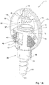
Fig. 1A is a schematic isometric view of a sprayer according to one example of the subject matter of the present application; -
Fig. 1B is a schematic exploded isometric view of the sprayer shown inFig. 1A ; -
Fig. 2 is a longitudinal cross-sectional view of a sprayer bridge of the sprayer shown inFig. 1B , taken along plane I-I; -
Fig. 3A is a schematic isometric view of a housing of the sprayer shown inFigs. 1A to 2 ; -
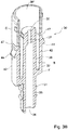
Fig. 3B is a schematic longitudinal cross-sectional view of the housing shown inFig. 3A ; -
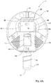
Figs. 4A and4B are schematic front views of the sprayer shown inFigs. 1A to 2 , in its respective open and closed positions; -
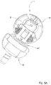
Fig. 5A is a schematic isometric view of a sprayer according to another example of the subject matter of the present application; -
Fig. 5B is a schematic exploded isometric view of the sprayer shown inFig. 5A ; -
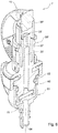
Fig. 6 is a longitudinal cross-sectional view of the sprayer shown inFigs. 5A and5B , taken along plane II-II; -
Figs. 7A and7B are schematic front views of the sprayer shown inFigs. 5A to 6 , in its respective open and closed positions; -
Fig. 8A is a schematic isometric view of a sprayer according to another example of the present application; -
Fig. 8B is a schematic longitudinal cross-section view of the sprayer shown inFig. 8A ; -
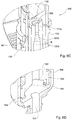
Figs. 8C and 8D are schematic enlarged views of details D and E shown inFig. 8B ; -
Fig. 8E is a schematic enlarged view of a latch member of the sprayer shown inFig. 8A ; and -
Fig. 9 is a schematic front view of the irrigation member of the sprayer shown inFigs. 8A to 8E . - Turning to
Figs. 1A and1B , a sprayer is shown generally designated 1 and comprising asprayer bridge 10 mounted over asprayer housing 30 in a displaceable manner. Thebridge 10 further comprises adispersion element 20 configured for dispersing fluid emitted from thesprayer housing 30. Thehousing 30 further comprises anengagement arrangement 40 configured for allowing controlled displacement of thebridge 10 over thehousing 30. - The
sprayer housing 30 is constituted by a single injection moldedbody 32 having aninlet end 34 and an opposite outlet end 36 (shown inFig. 3B ) about which is elevated a protectingsleeve 36'. Theinlet end 34 is configured for fixed attachment to a fluid source (a tank, a pipe etc.) via anattachment portion 33 having adedicated thread 31. - The
engagement arrangement 40 of thehousing 30 comprises twolateral wings 42 which are inwardly depressible with respect to thehousing body 32, eachwing 42 comprising a snap-type latch 44 projecting outwardly from thehousing body 32. Thewings 42 are arranged diametrically opposite one another, i.e. disposed at 180° about a longitudinal axis X of thehousing 32. - The
engagement arrangement 40 further comprises twolongitudinal guides 46, also diametrically opposed, but angularly spaced 90° from thewings 42. Theguides 46 extend the majority of the length of thehousing body 32 and are formed, at an end thereof closer to thefluid outlet 36 protected by thesleeve 36', with restrictingprojections 48, configured for restricting the movement of the bridge in a non-axial direction (i.e. limiting circular runout of the bridge). - In addition, it is noted that the housing further comprise two protrusions C configured for reducing the radial degree of freedom of the bridge over the housing, at least when in the open position thereof. Specifically, the protrusions C bridge the gap formed between the
bridge 10 and thehousing 30. - With additional reference being made to
Figs. 3A and3B , thehousing 32 is hollow and accommodates therein anoutlet nozzle 39 having anoutlet channel 37. It is appreciated that the diameter of thechannel 37 is considerably smaller than the diameter of achannel 35 leading thereto from thefluid inlet 34, the diameter being defined according to the desired flow-rate through thesprayer 1. - It is observed that there extends an annular basin B about the
nozzle 39, configured for accumulating therein of clogging material (e.g. dirt, mud etc.). The arrangement is such that the basin floor F is located much lower than theoutlet 37 of thenozzle 39, whereby such accumulated material does not block thenozzle 39. - In addition, it is appreciated that there are two
slots 47 extending on both sides of the housing, configured, among other things, for drainage of accumulated material from the basin B. A top-most end of theslots 47 is also located below the level of thenozzle outlet 37, so that material accumulated in the basin F can be drained from the housing before rising to a level blocking thenozzle 39. - The
bridge 10 comprises a hollow mountingportion 12 configured for receiving therein thesprayer housing 32. The mountingportion 12 is formed with two diametricallyopposed windows 13 configured for slidingly receiving therein the snap-type latches 44 of theengagement arrangement 40 and two diametricallyopposed slots 17 configured for receiving therein theguides 46. - The
bridge 10 comprises a round top structure constituted by two diametricallyopposed arms 14 extending from the mountingportion 12 and meeting at abridge head 18 elevated over the mountingportion 12. Thedispersion element 20 is integrally formed with thebridge head 18 and disposed between it and the mountingportion 12. - It is also observed that each of the
arms 14 is formed with two slopingsurfaces 16 forming a dividingridge 16 facing the central axis of thesprayer 1. In operation, the dividingridge 16 serves to prevent obstruction of the fluid dispersed by thecrown 20. - Turning now to
Figs. 4Aa and4B , thesprayer 1 is shown attached to a fluid source B via theattachment portion 33. It is noted that this attachment is fixed (i.e. thehousing 32 does not displace with respect to the source B at least during operation). - In the position shown in
Fig. 4A , thesprayer 1 is in its closed position, the mountingportion 12 of thebridge 10 being received over a bottom portion of thehousing body 32 so that thedispersion element 20 rests on the rim of the protectingsleeve 36', thereby sealing it. It is also noted that in the above position, thetop end 13b of thewindow 13 is proximal to thelatch 44. - In the above position, fluid is not passed between the
inlet 34 and theoutlet 36, and thesleeve 36' is sealed, preventing from dirt and insects from passing into the hollow 38 of the housing body 32 (which may disrupt operation of the sprayer 1). - Turning now to
Fig. 4B , in operation, fluid passed into theinlet 34 and emitted from thenozzle 37 as a fluid jet is emitted from theoutlet 36 at sufficient pressure as to elevate thecrown 20 over the rim of thesleeve 36'. Under such pressure, theentire bridge 10 is displaced upwards so that there is formed a gap g between thecrown 20 and thesleeve 36'. - In this position, fluid emitted from the
outlet 36 impacts thecrown 20 which then disperses the fluid jet by virtue of its geometric shape -teeth 24 arranged about thecrown body 22. It is also noted that fluid is dispersed from thecrown 20 in a radially outwards direction, whereby the shape of thearm 14 and in particular the dividingridge 16 prevent obstruction of the emitted fluid. - It is also noted that the
sprayer 1 is a directional sprayer which is designed to disperse fluid in only a predetermined sector. Specifically in the described example, thecrown teeth 24 cover only about 270° (and not the entire 360). However, it is appreciated that a plurality of dispersion crowns can be contemplated, each having a different dispersion profile based on specific irrigation requirements. - In the open position shown in
Fig. 4 , the pressure of the fluid pushes the bridge upwards but its movement is restricted by thelatches 44 of thewings 42. In particular, in the open position, thebottom portion 13a of thewindow 13 abuts thelatches 44, which prevent further upward displacement of thebridge 10. - Once fluid flow is ceased, the pressure on the
crown 20 drops, whereby theentire bridge 10 falls back to its closed position (shown inFig. 4A ), by virtue of gravitational forces. - It is noted that in both position, closed and open, shown in
Figs. 4A and4B , thefluid inlet 34 remains fixed and the distance of thefluid outlet 36 does not vary with respect to thefluid inlet 34. To the contrary, the mobile part of thesprayer 1 is thebridge 10 and not thefluid outlet 36. - Turning now to
Figs. 5A and5B , another example of a sprayer is shown, generally designated 1'. Under this design, the sprayer 1' comprises asimilar bridge 10, but a modified housing 30' which is configured for articulation to anadditional member 50 and comprising a flow-rate regulator 60. - Under this arrangement, the housing 30' comprises the
sleeve 36" and theadditional member 50 comprises thefluid inlet 54 which is configured for fixed attachment to a fluid source. - A bottom portion of the housing 30' is formed with a flow-
rate regulator structure 60 configured for accommodating asealing ring 80 and adiaphragm 70, for the purpose of regulating fluid flow from theinlet 54 to the outlet 39', as shown inFig. 6 . - The operation of the sprayer 1' is essentially identical to the operation of
sprayer 1, with the difference being in the structure of the housing 30'. In particular, in this case as well, thefluid inlet 54 remains in fixed attachment to the source via its connectingportion 53, and the distance between thefluid inlet 54 and the fluid outlet 39' remains fixed. - Turning now to
Figs. 8A to 9 , another embodiment of a sprayer is shown, generally designated 101, and which is similar to the previously described sprayer 1'. Elements ofsprayer 101 similar to those of sprayer 1' are designated by the same reference numbers, upped by a 100, so thatelement 132 ofsprayer 101 is similar to element 32' of sprayer 1' etc. - The
sprayer 101 differs from the sprayer 1' by the design of several elements as will be described below. - First of all, the nozzle is not in the form of a straight channel (as nozzle 37'), and now comprises three segments: a top
straight segment 137a of a small diameter, a conical/tapering segment 137b and a bottomstraight segment 137c, thereby defining a tapering shape of the nozzle. Using a diverging design of the nozzle can facilitate better emission of fluid from the sprayer and more convenient control over the pressure of the irrigation fluid within the nozzle. - Secondly, the
latch 134 is provided with aprojection 135 which is configured for being received within a correspondingnook 115 of thebridge member 110. Engagement between theprojection 135 andnook 115 facilitates restricting thespray member 130 from performing a tilting movement about the longitudinal axis of thesprayer 101. - Furthermore, with particular reference being made to
Fig. 9 , it is noted that one of theguide members 148 of the sprayer is provided with aflat portion 149 configured for providing a more efficient plastic molding process when manufacturing the sprayer. In particular, thisflat portion 149 is formed by a piece of the mold allowing more convenient injection of the molten plastic during injection molding. - Another difference between the
sprayer 101 and the sprayer 1' lies in the configuration of thebottom portion 162 ofelement 160 which is configured for holding the diaphragm in place. Under the present design, thebottom portion 162 compriseslegs 164 circumferentially spaced about the central axis of the sprayer and configured for retaining therein the diaphragm. - Those skilled in the art to which this invention pertains will readily appreciate that numerous changes, variations, and modifications can be made without departing from the scope of the invention, mutatis mutandis.
Claims (18)
- A sprayer (1) comprising:a housing (30) having a fluid inlet (34) configured for being statically coupled to a fluid source to receive fluid therefrom and a fluid outlet (36) configured for the discharging said fluid, the distance between said fluid inlet (34) and said fluid outlet (36,36') being fixed; anda bridge (10) mounted over the housing (30) and comprising a dispersion element (20) configured for dispersing fluid discharged from the fluid outlet (36,36') of the housing (30);characterised in that the bridge (10) is configured for displacement over the housing (30) at least between a closed position in which the dispersion element (20) comes into contact with the fluid outlet (36,36') to thereby seal it, and an open position in which the dispersion element (20) is spaced from the fluid outlet (36,36') by a gap, allowing dispersion of the fluid.
- A sprayer (1) according to Claim 1, wherein the housing (30) forms a unitary body in which the fluid outlet (36,36') is stationary with respect to the fluid inlet (34) during operation and wherein the fluid inlet (34) and fluid outlet (36,36') are opposite to each other.
- A sprayer (1) according to any one of Claims 1 to 2, wherein the bridge (10) is constantly urged into the closed position and displacement of the bridge (10) from the closed position to the open position is facilitated by the pressure of fluid emitted through the fluid outlet (36,36').
- A sprayer (1) according to Claim 3, wherein the sprayer (1) comprises a biasing spring configured for constantly urging the bridge (10) into the closed position.
- A sprayer (1) according to any one of Claims 1 to 4, wherein displacement of the bridge (10) over the housing (30) is facilitated by guides (46) formed in the housing (30) and the bridge (10) and configured to engage one another to determine a displacement path of the bridge (10).
- A sprayer (1) according to any one of Claims 1 to 5, wherein the bridge (10) comprises a mounting portion (12) configured for being displaceably fitted over the housing (30) and at least one arm (14) articulating the dispersion element (20) to the mounting portion (12).
- A sprayer (1) according to any one of Claims 1 to 6, wherein the sprayer (1) comprises at least an open limiter configured for restricting displacement of the bridge (10) over the housing (30) beyond the open position by limiting the traveling distance between the dispersion element (20) and the fluid outlet (36,36') so as not to exceed the operational gap.
- A sprayer (1) according to any one of Claims 1 to 7, wherein the sprayer (1) comprises a closed limiter, configured, in the closed position, for preventing displacement of the bridge (10) over the housing (30) beyond the closed position.
- A sprayer (1) according to Claims 7 and 8, wherein one of the bridge (10) and the housing (30) comprises a channel having a first end and a second end, and the other of the two comprises a restricting member configured for being received within the channel and displaced therein.
- A sprayer (1) according to Claim 9, wherein limiting of the displacement at the open position is provided by engagement of the restricting member with the first end of the channel and limiting of the displacement at the closed position is provided by engagement of the restricting member with the second end of the channel.
- A sprayer (1) according to any one of Claims 1 to 10, wherein the dispersion element (20) is spaced from the mounting portion (12) by virtue of at least one articulating arm (14) having a first end associated with the mounting portion (12) and another end associated with the fluid outlet (36,36').
- A sprayer (1) according to any one of Claims 1 to 11, wherein the housing (30) comprises a sleeve portion having an open end delimited by a rim constituting the fluid outlet (36') of the housing (30), and a nozzle having a nozzle outlet disposed at or below the level of the rim.
- A sprayer (1) according to Claim 12, wherein, in the closed position of the sprayer (1), the rim of the sleeve portion is sealed by the dispersing element (20) while the nozzle is located within the sleeve portion.
- A sprayer (1) according to claim 12 or 13, wherein, in the closed position of the sprayer (1), a mounting portion (12) of the bridge (10) is received over a bottom portion of the housing so that the dispersion element rests on the rim of the sleeve portion, thereby sealing it.
- A sprayer (1) according to claim 14, wherein, in the closed position, fluid is not passed between the inlet and the outlet and the rim of the sleeve portion is sealed, thereby preventing dirt and insects from passing into a hollow of the housing.
- A sprayer (1) according to Claim 12 or 13, wherein the sleeve portion has a diameter greater than that of the nozzle, thereby yielding an annular basin extending about the nozzle.
- A sprayer (1) according to claim 16, wherein the annular basin has a bottom surface disposed below the level of the nozzle outlet, whereby dirt, mud and clogging material can be accumulated within the basin, around the nozzle, without blocking the nozzle outlet.
- A sprayer (1) according to Claim 16 or 17, wherein the sleeve portion is provided with at least one drainage opening configured for draining material from the basin.
Applications Claiming Priority (2)
| Application Number | Priority Date | Filing Date | Title |
|---|---|---|---|
| IL227462A IL227462A (en) | 2013-07-14 | 2013-07-14 | Sprayer |
| PCT/IL2014/050633 WO2015008278A1 (en) | 2013-07-14 | 2014-07-13 | Sprayer |
Publications (2)
| Publication Number | Publication Date |
|---|---|
| EP3021985A1 EP3021985A1 (en) | 2016-05-25 |
| EP3021985B1 true EP3021985B1 (en) | 2018-01-10 |
Family
ID=49784230
Family Applications (1)
| Application Number | Title | Priority Date | Filing Date |
|---|---|---|---|
| EP14752435.9A Not-in-force EP3021985B1 (en) | 2013-07-14 | 2014-07-13 | Sprayer |
Country Status (8)
| Country | Link |
|---|---|
| US (1) | US10183301B2 (en) |
| EP (1) | EP3021985B1 (en) |
| CN (1) | CN105682806B (en) |
| AU (1) | AU2014291661B2 (en) |
| ES (1) | ES2665448T3 (en) |
| IL (1) | IL227462A (en) |
| MX (1) | MX2016000576A (en) |
| WO (1) | WO2015008278A1 (en) |
Families Citing this family (2)
| Publication number | Priority date | Publication date | Assignee | Title |
|---|---|---|---|---|
| US10322423B2 (en) | 2016-11-22 | 2019-06-18 | Rain Bird Corporation | Rotary nozzle |
| US11406999B2 (en) * | 2019-05-10 | 2022-08-09 | Rain Bird Corporation | Irrigation nozzle with one or more grit vents |
Family Cites Families (15)
| Publication number | Priority date | Publication date | Assignee | Title |
|---|---|---|---|---|
| US2975981A (en) * | 1959-07-07 | 1961-03-21 | Haggie I Cockman | Sprinkler |
| US3309025A (en) * | 1965-07-06 | 1967-03-14 | Rain Bird Sprinkler Mfg | Self-cleaning spray deflector wedge for sprinklers |
| US3432102A (en) * | 1966-10-03 | 1969-03-11 | Sherman Mfg Co H B | Liquid dispensing apparatus,motor and method |
| US4121769A (en) * | 1976-04-14 | 1978-10-24 | Mordeki Drori | Rotary spraying device particularly useful for water irrigation |
| IT1206446B (en) * | 1978-03-23 | 1989-04-21 | Mair Hermine Ora Ditta Pierre | HYDRODYNAMIC RAIN SPRINKLER. |
| US4177944A (en) * | 1978-08-16 | 1979-12-11 | Rain Bird Sprinkler Mfg. Corp. | Rotary irrigation sprinkler |
| US4538689A (en) * | 1978-08-17 | 1985-09-03 | Dmi, Inc. | Subsoil plow point |
| US4369922A (en) * | 1978-12-19 | 1983-01-25 | Vikre Merle A | Sprinkler head for a center pivot irrigation system |
| US4512519A (en) | 1982-10-05 | 1985-04-23 | Mifalei Matechet Naan | Sprinkler |
| ZA841115B (en) | 1983-02-22 | 1984-09-26 | Nakachian Raymond J | Distributor or dripper for the micro-irrigation of soils |
| US4754925A (en) * | 1984-10-24 | 1988-07-05 | Zvi Rubinstein | Rotating miniature sprinkler for irrigation systems |
| CN2231580Y (en) * | 1995-09-13 | 1996-07-24 | 上海万得凯塑料五金制品有限公司 | Miniature spray head |
| CN2254381Y (en) * | 1996-01-18 | 1997-05-21 | 丁维东 | Water bird rotary disk type sprinkler head |
| CN2557242Y (en) * | 2002-03-07 | 2003-06-25 | 杜利民 | Spraying head |
| IL157246A (en) | 2003-08-05 | 2012-10-31 | Naan Dan Irrigation Systems Ltd | Pop-up sprinkler |
-
2013
- 2013-07-14 IL IL227462A patent/IL227462A/en active IP Right Grant
-
2014
- 2014-07-13 WO PCT/IL2014/050633 patent/WO2015008278A1/en not_active Ceased
- 2014-07-13 US US14/905,231 patent/US10183301B2/en active Active
- 2014-07-13 CN CN201480043597.6A patent/CN105682806B/en not_active Expired - Fee Related
- 2014-07-13 ES ES14752435.9T patent/ES2665448T3/en active Active
- 2014-07-13 EP EP14752435.9A patent/EP3021985B1/en not_active Not-in-force
- 2014-07-13 MX MX2016000576A patent/MX2016000576A/en unknown
- 2014-07-13 AU AU2014291661A patent/AU2014291661B2/en not_active Ceased
Also Published As
| Publication number | Publication date |
|---|---|
| CN105682806B (en) | 2019-05-17 |
| US20160151795A1 (en) | 2016-06-02 |
| IL227462A (en) | 2016-08-31 |
| AU2014291661A1 (en) | 2016-02-04 |
| AU2014291661B2 (en) | 2018-09-20 |
| ES2665448T3 (en) | 2018-04-25 |
| US10183301B2 (en) | 2019-01-22 |
| EP3021985A1 (en) | 2016-05-25 |
| CN105682806A (en) | 2016-06-15 |
| IL227462A0 (en) | 2013-12-31 |
| MX2016000576A (en) | 2016-07-08 |
| WO2015008278A1 (en) | 2015-01-22 |
Similar Documents
| Publication | Publication Date | Title |
|---|---|---|
| US9138768B2 (en) | Pop-up irrigation device for use with low-pressure irrigation systems | |
| US6145758A (en) | Variable arc spray nozzle | |
| AU2010202918B2 (en) | Pop-up sprinkler with integrated pressure regulator and drain check | |
| EP2315516B1 (en) | Watering device | |
| US6158675A (en) | Sprinkler spray head | |
| US9022059B2 (en) | Flow regulator for agricultural drip emitter | |
| ES2885900T3 (en) | Pressure regulator comprising a single strut seat with strut coaxial to a piston | |
| US4817869A (en) | Rotating miniature sprinkler for irrigation systems | |
| US8567696B2 (en) | Nozzle body for use with irrigation devices | |
| US8083158B2 (en) | Pop-up sprinkler | |
| WO2006034060A1 (en) | Pop-up irrigation sprinklers | |
| CN110730613B (en) | Drain check in pressure regulator | |
| CN107969151B (en) | Pressure Control Devices for Liquids | |
| US9573145B2 (en) | Pressure regulating nozzle assembly | |
| AU2007311423A2 (en) | Rotary sprinkler | |
| MX2011001376A (en) | SPRAYER. | |
| US9616435B2 (en) | Self-cleaning sprinkler | |
| AU2014291661B2 (en) | Sprayer | |
| US20070119975A1 (en) | Method and Apparatus for Reducing the Precipitation Rate of an Irrigation Sprinkler | |
| US5381959A (en) | Static sprayer including protective cover | |
| US20230088593A1 (en) | Oscillating sprinkler assembly | |
| US5358180A (en) | Selectable spray pattern low volume sprinkler | |
| US4616780A (en) | Pop-up sprinkler | |
| KR200484312Y1 (en) | Rotational Ejecting Sprinkler Hose for Plant Cultivation With Waterdrop Prevention Function | |
| JP5651155B2 (en) | Sprinkler |
Legal Events
| Date | Code | Title | Description |
|---|---|---|---|
| PUAI | Public reference made under article 153(3) epc to a published international application that has entered the european phase |
Free format text: ORIGINAL CODE: 0009012 |
|
| 17P | Request for examination filed |
Effective date: 20160215 |
|
| AK | Designated contracting states |
Kind code of ref document: A1 Designated state(s): AL AT BE BG CH CY CZ DE DK EE ES FI FR GB GR HR HU IE IS IT LI LT LU LV MC MK MT NL NO PL PT RO RS SE SI SK SM TR |
|
| AX | Request for extension of the european patent |
Extension state: BA ME |
|
| DAX | Request for extension of the european patent (deleted) | ||
| GRAP | Despatch of communication of intention to grant a patent |
Free format text: ORIGINAL CODE: EPIDOSNIGR1 |
|
| STAA | Information on the status of an ep patent application or granted ep patent |
Free format text: STATUS: GRANT OF PATENT IS INTENDED |
|
| INTG | Intention to grant announced |
Effective date: 20170328 |
|
| GRAJ | Information related to disapproval of communication of intention to grant by the applicant or resumption of examination proceedings by the epo deleted |
Free format text: ORIGINAL CODE: EPIDOSDIGR1 |
|
| STAA | Information on the status of an ep patent application or granted ep patent |
Free format text: STATUS: REQUEST FOR EXAMINATION WAS MADE |
|
| INTC | Intention to grant announced (deleted) | ||
| GRAS | Grant fee paid |
Free format text: ORIGINAL CODE: EPIDOSNIGR3 |
|
| STAA | Information on the status of an ep patent application or granted ep patent |
Free format text: STATUS: GRANT OF PATENT IS INTENDED |
|
| GRAP | Despatch of communication of intention to grant a patent |
Free format text: ORIGINAL CODE: EPIDOSNIGR1 |
|
| INTG | Intention to grant announced |
Effective date: 20171009 |
|
| GRAA | (expected) grant |
Free format text: ORIGINAL CODE: 0009210 |
|
| STAA | Information on the status of an ep patent application or granted ep patent |
Free format text: STATUS: THE PATENT HAS BEEN GRANTED |
|
| AK | Designated contracting states |
Kind code of ref document: B1 Designated state(s): AL AT BE BG CH CY CZ DE DK EE ES FI FR GB GR HR HU IE IS IT LI LT LU LV MC MK MT NL NO PL PT RO RS SE SI SK SM TR |
|
| REG | Reference to a national code |
Ref country code: CH Ref legal event code: EP Ref country code: AT Ref legal event code: REF Ref document number: 961820 Country of ref document: AT Kind code of ref document: T Effective date: 20180115 |
|
| REG | Reference to a national code |
Ref country code: IE Ref legal event code: FG4D |
|
| REG | Reference to a national code |
Ref country code: DE Ref legal event code: R096 Ref document number: 602014019677 Country of ref document: DE |
|
| REG | Reference to a national code |
Ref country code: RO Ref legal event code: EPE |
|
| REG | Reference to a national code |
Ref country code: ES Ref legal event code: FG2A Ref document number: 2665448 Country of ref document: ES Kind code of ref document: T3 Effective date: 20180425 |
|
| REG | Reference to a national code |
Ref country code: NL Ref legal event code: MP Effective date: 20180110 |
|
| REG | Reference to a national code |
Ref country code: AT Ref legal event code: MK05 Ref document number: 961820 Country of ref document: AT Kind code of ref document: T Effective date: 20180110 |
|
| PG25 | Lapsed in a contracting state [announced via postgrant information from national office to epo] |
Ref country code: NL Free format text: LAPSE BECAUSE OF FAILURE TO SUBMIT A TRANSLATION OF THE DESCRIPTION OR TO PAY THE FEE WITHIN THE PRESCRIBED TIME-LIMIT Effective date: 20180110 |
|
| REG | Reference to a national code |
Ref country code: FR Ref legal event code: PLFP Year of fee payment: 5 |
|
| PG25 | Lapsed in a contracting state [announced via postgrant information from national office to epo] |
Ref country code: LT Free format text: LAPSE BECAUSE OF FAILURE TO SUBMIT A TRANSLATION OF THE DESCRIPTION OR TO PAY THE FEE WITHIN THE PRESCRIBED TIME-LIMIT Effective date: 20180110 Ref country code: HR Free format text: LAPSE BECAUSE OF FAILURE TO SUBMIT A TRANSLATION OF THE DESCRIPTION OR TO PAY THE FEE WITHIN THE PRESCRIBED TIME-LIMIT Effective date: 20180110 Ref country code: FI Free format text: LAPSE BECAUSE OF FAILURE TO SUBMIT A TRANSLATION OF THE DESCRIPTION OR TO PAY THE FEE WITHIN THE PRESCRIBED TIME-LIMIT Effective date: 20180110 Ref country code: NO Free format text: LAPSE BECAUSE OF FAILURE TO SUBMIT A TRANSLATION OF THE DESCRIPTION OR TO PAY THE FEE WITHIN THE PRESCRIBED TIME-LIMIT Effective date: 20180410 Ref country code: CY Free format text: LAPSE BECAUSE OF FAILURE TO SUBMIT A TRANSLATION OF THE DESCRIPTION OR TO PAY THE FEE WITHIN THE PRESCRIBED TIME-LIMIT Effective date: 20180110 |
|
| PG25 | Lapsed in a contracting state [announced via postgrant information from national office to epo] |
Ref country code: SE Free format text: LAPSE BECAUSE OF FAILURE TO SUBMIT A TRANSLATION OF THE DESCRIPTION OR TO PAY THE FEE WITHIN THE PRESCRIBED TIME-LIMIT Effective date: 20180110 Ref country code: LV Free format text: LAPSE BECAUSE OF FAILURE TO SUBMIT A TRANSLATION OF THE DESCRIPTION OR TO PAY THE FEE WITHIN THE PRESCRIBED TIME-LIMIT Effective date: 20180110 Ref country code: PL Free format text: LAPSE BECAUSE OF FAILURE TO SUBMIT A TRANSLATION OF THE DESCRIPTION OR TO PAY THE FEE WITHIN THE PRESCRIBED TIME-LIMIT Effective date: 20180110 Ref country code: GR Free format text: LAPSE BECAUSE OF FAILURE TO SUBMIT A TRANSLATION OF THE DESCRIPTION OR TO PAY THE FEE WITHIN THE PRESCRIBED TIME-LIMIT Effective date: 20180411 Ref country code: IS Free format text: LAPSE BECAUSE OF FAILURE TO SUBMIT A TRANSLATION OF THE DESCRIPTION OR TO PAY THE FEE WITHIN THE PRESCRIBED TIME-LIMIT Effective date: 20180510 Ref country code: AT Free format text: LAPSE BECAUSE OF FAILURE TO SUBMIT A TRANSLATION OF THE DESCRIPTION OR TO PAY THE FEE WITHIN THE PRESCRIBED TIME-LIMIT Effective date: 20180110 Ref country code: RS Free format text: LAPSE BECAUSE OF FAILURE TO SUBMIT A TRANSLATION OF THE DESCRIPTION OR TO PAY THE FEE WITHIN THE PRESCRIBED TIME-LIMIT Effective date: 20180110 Ref country code: BG Free format text: LAPSE BECAUSE OF FAILURE TO SUBMIT A TRANSLATION OF THE DESCRIPTION OR TO PAY THE FEE WITHIN THE PRESCRIBED TIME-LIMIT Effective date: 20180410 |
|
| PGFP | Annual fee paid to national office [announced via postgrant information from national office to epo] |
Ref country code: RO Payment date: 20180629 Year of fee payment: 5 |
|
| REG | Reference to a national code |
Ref country code: DE Ref legal event code: R097 Ref document number: 602014019677 Country of ref document: DE |
|
| PG25 | Lapsed in a contracting state [announced via postgrant information from national office to epo] |
Ref country code: AL Free format text: LAPSE BECAUSE OF FAILURE TO SUBMIT A TRANSLATION OF THE DESCRIPTION OR TO PAY THE FEE WITHIN THE PRESCRIBED TIME-LIMIT Effective date: 20180110 Ref country code: EE Free format text: LAPSE BECAUSE OF FAILURE TO SUBMIT A TRANSLATION OF THE DESCRIPTION OR TO PAY THE FEE WITHIN THE PRESCRIBED TIME-LIMIT Effective date: 20180110 |
|
| PGFP | Annual fee paid to national office [announced via postgrant information from national office to epo] |
Ref country code: FR Payment date: 20180724 Year of fee payment: 5 Ref country code: ES Payment date: 20180810 Year of fee payment: 5 Ref country code: GB Payment date: 20180622 Year of fee payment: 5 Ref country code: IT Payment date: 20180724 Year of fee payment: 5 Ref country code: DE Payment date: 20180711 Year of fee payment: 5 |
|
| PLBE | No opposition filed within time limit |
Free format text: ORIGINAL CODE: 0009261 |
|
| STAA | Information on the status of an ep patent application or granted ep patent |
Free format text: STATUS: NO OPPOSITION FILED WITHIN TIME LIMIT |
|
| PG25 | Lapsed in a contracting state [announced via postgrant information from national office to epo] |
Ref country code: DK Free format text: LAPSE BECAUSE OF FAILURE TO SUBMIT A TRANSLATION OF THE DESCRIPTION OR TO PAY THE FEE WITHIN THE PRESCRIBED TIME-LIMIT Effective date: 20180110 Ref country code: SM Free format text: LAPSE BECAUSE OF FAILURE TO SUBMIT A TRANSLATION OF THE DESCRIPTION OR TO PAY THE FEE WITHIN THE PRESCRIBED TIME-LIMIT Effective date: 20180110 Ref country code: CZ Free format text: LAPSE BECAUSE OF FAILURE TO SUBMIT A TRANSLATION OF THE DESCRIPTION OR TO PAY THE FEE WITHIN THE PRESCRIBED TIME-LIMIT Effective date: 20180110 Ref country code: SK Free format text: LAPSE BECAUSE OF FAILURE TO SUBMIT A TRANSLATION OF THE DESCRIPTION OR TO PAY THE FEE WITHIN THE PRESCRIBED TIME-LIMIT Effective date: 20180110 |
|
| 26N | No opposition filed |
Effective date: 20181011 |
|
| RIC2 | Information provided on ipc code assigned after grant |
Ipc: B05B 15/10 20181130AFI20150203BHEP Ipc: B05B 3/04 20060101ALI20150203BHEP |
|
| REG | Reference to a national code |
Ref country code: CH Ref legal event code: PK Free format text: BERICHTIGUNGEN |
|
| REG | Reference to a national code |
Ref country code: CH Ref legal event code: PK Free format text: BERICHTIGUNGEN |
|
| RIC2 | Information provided on ipc code assigned after grant |
Ipc: B05B 15/10 20060101AFI20150203BHEP Ipc: B05B 3/04 20060101ALI20150203BHEP |
|
| PG25 | Lapsed in a contracting state [announced via postgrant information from national office to epo] |
Ref country code: SI Free format text: LAPSE BECAUSE OF FAILURE TO SUBMIT A TRANSLATION OF THE DESCRIPTION OR TO PAY THE FEE WITHIN THE PRESCRIBED TIME-LIMIT Effective date: 20180110 |
|
| REG | Reference to a national code |
Ref country code: CH Ref legal event code: PL |
|
| PG25 | Lapsed in a contracting state [announced via postgrant information from national office to epo] |
Ref country code: MC Free format text: LAPSE BECAUSE OF FAILURE TO SUBMIT A TRANSLATION OF THE DESCRIPTION OR TO PAY THE FEE WITHIN THE PRESCRIBED TIME-LIMIT Effective date: 20180110 Ref country code: LU Free format text: LAPSE BECAUSE OF NON-PAYMENT OF DUE FEES Effective date: 20180713 |
|
| REG | Reference to a national code |
Ref country code: BE Ref legal event code: MM Effective date: 20180731 |
|
| REG | Reference to a national code |
Ref country code: IE Ref legal event code: MM4A |
|
| PG25 | Lapsed in a contracting state [announced via postgrant information from national office to epo] |
Ref country code: LI Free format text: LAPSE BECAUSE OF NON-PAYMENT OF DUE FEES Effective date: 20180731 Ref country code: CH Free format text: LAPSE BECAUSE OF NON-PAYMENT OF DUE FEES Effective date: 20180731 Ref country code: IE Free format text: LAPSE BECAUSE OF NON-PAYMENT OF DUE FEES Effective date: 20180713 |
|
| PG25 | Lapsed in a contracting state [announced via postgrant information from national office to epo] |
Ref country code: BE Free format text: LAPSE BECAUSE OF NON-PAYMENT OF DUE FEES Effective date: 20180731 |
|
| PG25 | Lapsed in a contracting state [announced via postgrant information from national office to epo] |
Ref country code: MT Free format text: LAPSE BECAUSE OF NON-PAYMENT OF DUE FEES Effective date: 20180713 |
|
| REG | Reference to a national code |
Ref country code: DE Ref legal event code: R119 Ref document number: 602014019677 Country of ref document: DE |
|
| GBPC | Gb: european patent ceased through non-payment of renewal fee |
Effective date: 20190713 |
|
| PG25 | Lapsed in a contracting state [announced via postgrant information from national office to epo] |
Ref country code: DE Free format text: LAPSE BECAUSE OF NON-PAYMENT OF DUE FEES Effective date: 20200201 Ref country code: GB Free format text: LAPSE BECAUSE OF NON-PAYMENT OF DUE FEES Effective date: 20190713 Ref country code: RO Free format text: LAPSE BECAUSE OF NON-PAYMENT OF DUE FEES Effective date: 20190713 |
|
| PG25 | Lapsed in a contracting state [announced via postgrant information from national office to epo] |
Ref country code: PT Free format text: LAPSE BECAUSE OF FAILURE TO SUBMIT A TRANSLATION OF THE DESCRIPTION OR TO PAY THE FEE WITHIN THE PRESCRIBED TIME-LIMIT Effective date: 20180110 |
|
| PG25 | Lapsed in a contracting state [announced via postgrant information from national office to epo] |
Ref country code: MK Free format text: LAPSE BECAUSE OF NON-PAYMENT OF DUE FEES Effective date: 20180110 Ref country code: HU Free format text: LAPSE BECAUSE OF FAILURE TO SUBMIT A TRANSLATION OF THE DESCRIPTION OR TO PAY THE FEE WITHIN THE PRESCRIBED TIME-LIMIT; INVALID AB INITIO Effective date: 20140713 Ref country code: FR Free format text: LAPSE BECAUSE OF NON-PAYMENT OF DUE FEES Effective date: 20190731 |
|
| PGFP | Annual fee paid to national office [announced via postgrant information from national office to epo] |
Ref country code: TR Payment date: 20200113 Year of fee payment: 6 |
|
| PG25 | Lapsed in a contracting state [announced via postgrant information from national office to epo] |
Ref country code: IT Free format text: LAPSE BECAUSE OF NON-PAYMENT OF DUE FEES Effective date: 20190713 |
|
| REG | Reference to a national code |
Ref country code: ES Ref legal event code: FD2A Effective date: 20201126 |
|
| PG25 | Lapsed in a contracting state [announced via postgrant information from national office to epo] |
Ref country code: ES Free format text: LAPSE BECAUSE OF NON-PAYMENT OF DUE FEES Effective date: 20190714 |
|
| PG25 | Lapsed in a contracting state [announced via postgrant information from national office to epo] |
Ref country code: TR Free format text: LAPSE BECAUSE OF NON-PAYMENT OF DUE FEES Effective date: 20200713 |