EP3021484A1 - Method and device for automatically adapting impedance, in particular for a channel transmitting or receiving radio frequencies - Google Patents
Method and device for automatically adapting impedance, in particular for a channel transmitting or receiving radio frequencies Download PDFInfo
- Publication number
- EP3021484A1 EP3021484A1 EP15191601.2A EP15191601A EP3021484A1 EP 3021484 A1 EP3021484 A1 EP 3021484A1 EP 15191601 A EP15191601 A EP 15191601A EP 3021484 A1 EP3021484 A1 EP 3021484A1
- Authority
- EP
- European Patent Office
- Prior art keywords
- impedance matching
- radio frequency
- impedance
- matching network
- input
- Prior art date
- Legal status (The legal status is an assumption and is not a legal conclusion. Google has not performed a legal analysis and makes no representation as to the accuracy of the status listed.)
- Granted
Links
- 238000000034 method Methods 0.000 title claims abstract description 36
- 238000005259 measurement Methods 0.000 claims description 45
- 230000005540 biological transmission Effects 0.000 claims description 25
- 230000010363 phase shift Effects 0.000 claims description 15
- FGUUSXIOTUKUDN-IBGZPJMESA-N C1(=CC=CC=C1)N1C2=C(NC([C@H](C1)NC=1OC(=NN=1)C1=CC=CC=C1)=O)C=CC=C2 Chemical compound C1(=CC=CC=C1)N1C2=C(NC([C@H](C1)NC=1OC(=NN=1)C1=CC=CC=C1)=O)C=CC=C2 FGUUSXIOTUKUDN-IBGZPJMESA-N 0.000 claims description 4
- 102100025199 Protein DBF4 homolog B Human genes 0.000 claims 2
- 101710158942 Protein diaphanous homolog 1 Proteins 0.000 claims 2
- 230000006978 adaptation Effects 0.000 abstract description 66
- 101150002963 DFR1 gene Proteins 0.000 abstract 1
- 235000021183 entrée Nutrition 0.000 description 18
- 238000004364 calculation method Methods 0.000 description 12
- 230000001939 inductive effect Effects 0.000 description 10
- 102100036469 Protein diaphanous homolog 2 Human genes 0.000 description 9
- 101710158950 Protein diaphanous homolog 2 Proteins 0.000 description 9
- 239000003990 capacitor Substances 0.000 description 9
- 238000010586 diagram Methods 0.000 description 6
- 238000005457 optimization Methods 0.000 description 6
- 241001080024 Telles Species 0.000 description 5
- 230000003071 parasitic effect Effects 0.000 description 5
- 241000004441 Sorites Species 0.000 description 2
- 230000002301 combined effect Effects 0.000 description 2
- 239000007788 liquid Substances 0.000 description 2
- 230000000630 rising effect Effects 0.000 description 2
- 238000004458 analytical method Methods 0.000 description 1
- 238000012550 audit Methods 0.000 description 1
- 230000002457 bidirectional effect Effects 0.000 description 1
- 239000008280 blood Substances 0.000 description 1
- 210000004369 blood Anatomy 0.000 description 1
- 238000012512 characterization method Methods 0.000 description 1
- 238000006243 chemical reaction Methods 0.000 description 1
- 238000007796 conventional method Methods 0.000 description 1
- 230000001419 dependent effect Effects 0.000 description 1
- 238000013461 design Methods 0.000 description 1
- 230000000694 effects Effects 0.000 description 1
- 230000007613 environmental effect Effects 0.000 description 1
- 238000007429 general method Methods 0.000 description 1
- 210000003205 muscle Anatomy 0.000 description 1
- 230000000737 periodic effect Effects 0.000 description 1
- 230000000717 retained effect Effects 0.000 description 1
- 239000000523 sample Substances 0.000 description 1
- 238000005070 sampling Methods 0.000 description 1
- 238000012360 testing method Methods 0.000 description 1
- 210000001519 tissue Anatomy 0.000 description 1
- 238000011144 upstream manufacturing Methods 0.000 description 1
Images


Classifications
-
- H—ELECTRICITY
- H03—ELECTRONIC CIRCUITRY
- H03H—IMPEDANCE NETWORKS, e.g. RESONANT CIRCUITS; RESONATORS
- H03H7/00—Multiple-port networks comprising only passive electrical elements as network components
- H03H7/38—Impedance-matching networks
- H03H7/40—Automatic matching of load impedance to source impedance
-
- H—ELECTRICITY
- H01—ELECTRIC ELEMENTS
- H01Q—ANTENNAS, i.e. RADIO AERIALS
- H01Q1/00—Details of, or arrangements associated with, antennas
- H01Q1/50—Structural association of antennas with earthing switches, lead-in devices or lightning protectors
-
- H—ELECTRICITY
- H04—ELECTRIC COMMUNICATION TECHNIQUE
- H04B—TRANSMISSION
- H04B1/00—Details of transmission systems, not covered by a single one of groups H04B3/00 - H04B13/00; Details of transmission systems not characterised by the medium used for transmission
- H04B1/02—Transmitters
- H04B1/04—Circuits
- H04B1/0458—Arrangements for matching and coupling between power amplifier and antenna or between amplifying stages
-
- H—ELECTRICITY
- H04—ELECTRIC COMMUNICATION TECHNIQUE
- H04B—TRANSMISSION
- H04B1/00—Details of transmission systems, not covered by a single one of groups H04B3/00 - H04B13/00; Details of transmission systems not characterised by the medium used for transmission
- H04B1/06—Receivers
- H04B1/16—Circuits
- H04B1/18—Input circuits, e.g. for coupling to an antenna or a transmission line
Definitions
- the invention relates to a method for automatic impedance matching of a radio frequency chain, such as a radiofrequency transmit or receive string, and more specifically to an automatic antenna matching method.
- the invention also relates to an automatic impedance adaptation module enabling the implementation of such a method, as well as radiofrequency transmission and reception strings comprising such an automatic impedance matching module. .
- the transmitting or receiving antenna can have an impedance strongly dependent on conditions outside the antenna, and depending in particular on the medium in which the antenna is placed. .
- the antenna in medical telemetry, it may be necessary to introduce the antenna into a probe placed in the human body, and the impedance then strongly depends on the biological medium in which the antenna is located. It depends on the electrical properties (conductivity, dielectric constant) of surrounding tissues (muscles, fat) or liquid medium (blood, other liquids) in which the antenna can be immersed.
- the antenna impedance may vary.
- the variations of antenna impedance are particularly sensitive for very small antennas having a high quality coefficient, used in applications with high miniaturization constraints.
- mismatch losses these losses result from the fact that the transmission channel that feeds the antenna, or the reception chain that receives a signal of the antenna is generally designed to have optimal performance when it is loaded (at the output for the transmission chain or at the input for the reception chain) by a well-defined nominal impedance; it has degraded performance when it is loaded by an impedance different from its nominal value. Mismatch losses can be up to 40 dB.
- an impedance matching network in English “matching network”, which makes that the transmission chain sees an impedance different from that of the antenna and preferably equal to the nominal value for which it was designed, for example 100 ohms or 500 ohms.
- the adaptation network is tunable, that is to say that its elements, capacitive and / or inductive, have adjustable values to take into account the environmental conditions of the antenna so that the adaptation is the best possible under any circumstances.
- the document US 2009/0130991 discloses a method of adjusting the reactance values of an impedance matching circuit arranged between a receiving antenna and a low noise amplifier in which the reactances of the elements of said matching circuit are iteratively adjusted so as to maximize the intensity of the output signal of said low noise amplifier.
- the convergence of the iterative optimization algorithm can be very slow.
- EP 2,037,576 , WO 2011/026858 , EP 2,509,222 and EP 2,509,227 describe various variants of an automatic impedance matching method of a radio frequency transmission or reception string, in which current and voltage measurements at the input (for a transmission channel) or at the output (for a reception channel) of the adaptation network make it possible to determine the antenna impedance.
- the knowledge thus obtained from the antenna impedance makes it possible to use conventional techniques, for example based on a Smith chart, to adjust the impedance values of the elements of the adaptation network so as to arrive at a suitable adaptation. 'impedance.
- the document US 2013/0069737 discloses a method of automatic impedance matching of a radio frequency transmission or reception string in which not only the reactance value of certain elements is modified, but also the topology of the adaptation network.
- a disadvantage of the automatic adaptation methods according to the prior art is that it does not take into account the losses introduced by the impedance matching network. These losses have their origin in the non-ideal behavior of the reactive elements (capacitors and chokes), whose impedance has a non-zero resistive component, and in some cases cases may be greater than the efficiency gain provided by the impedance matching.
- the invention aims to remedy the aforementioned drawbacks of the prior art. More particularly, it aims to provide an automatic impedance matching method allowing the losses introduced by the impedance matching network to be taken into account, while being simple to implement and convergent quickly. It also aims to provide an impedance matching module for implementing such a method.
- Another object of the invention is an automatic impedance matching module intended to be arranged between a first radiofrequency device and a second radio frequency device, said module comprising: an impedance matching network having an input for connection to said first radio frequency device and an output for connection to said second radio frequency device, said impedance matching network comprising a plurality of reactive elements at least one of which has a variable reactance; a current and voltage measuring device arranged to measure a current and a voltage at the input or output of said impedance matching network; at least one first configuration device of said impedance matching network, adapted to modify the reactance of said or each said reactive element having a variable reactance; and a data processor configured to receive input current and voltage measurements from said measurement device and to output control signals from said one or more first configuration devices; characterized in that: said impedance matching network has a reconfigurable topology; the module also comprises at least a second configuration device of said impedance matching network, able to modify its topology; said data processor is configured to determine a topology of said matching network and
- Yet another object of the invention is a radiofrequency transmission chain comprising a power amplifier, an antenna and such an automatic impedance matching module connected between an output of said power amplifier and an input port of said antenna.
- Yet another object of the invention is a radio frequency reception chain comprising an antenna, a low-noise amplifier and such an automatic impedance matching module connected between an output port of said antenna and an input of said low-level amplifier. noise.
- Radio frequency means any frequency between 3 kHz and 300 GHz.
- power amplifier means an amplifier whose output is connected to or intended to be connected, directly or indirectly, to an emitter antenna.
- low-noise amplifier means an amplifier whose input is connected to or intended to be connected, directly or indirectly, to a receiving antenna.
- Reactive element means an electrical component whose impedance has, at at least one frequency in the radiofrequency domain, a reactive component (capacitive or inductive) greater than or equal to - and preferably greater by a factor of 10 or more - its resistive component.
- topology of an electrical network is defined by the set of elements that make it up (capacitors, chokes, resistances, etc.) and their interconnection, ignoring the value of their resistance, inductance or capacity. It is understood that several elements of the same type connected in series or in parallel are considered as constituting a single element. Thus one does not change topology by replacing, for example, a single capacitor by two capacitors connected in parallel.
- the Figure 1A represents the functional block diagram of an automatic impedance matching module according to an embodiment of the invention, inserted into a radio frequency chain.
- the module comprises a configurable impedance matching network RAC having two gates, two measuring devices DME, DMS arranged at said gates (but in fact only one may suffice), a data processor PD receiving input data of measurement generated by said devices measuring and generating control signals for two control devices DC1, DC2 which configure the RAC network.
- the two gates of the impedance matching network RAC are connected to a first radio frequency device DRF1 and a second radio frequency device DRF2, respectively.
- the first radiofrequency device DRF1 is a power amplifier AP and the second radio frequency device DRF2 is an antenna ANT operating in transmission (see FIG. figure 3 ), whereby the radio frequency chain is a transmission channel; filters may also be provided between the amplifier and the impedance matching network and / or between the latter and the antenna.
- the first radiofrequency device DRF1 may be an ANT antenna operating in reception and the second radio frequency device DRF2 may be an ABB low noise amplifier, whereby the radiofrequency channel is a radio frequency chain. reception.
- the measurement impedances Z MCE , Z MCS are reactive, and more preferably, capacitive.
- the measurements are made in differential mode, so that each measuring device comprises two identical measuring capacities, but this is not essential.
- Each VM device is essentially constituted by a conventional frequency change circuit and an analog-digital converter.
- the voltages at the terminals of the measurement impedances are electrical signals at the carrier frequency f.
- circuit elements present in the radiofrequency reception circuits of the system may be used to constitute this measuring circuit. Indeed, if the system operates in transmission and reception, the receiving part has frequency change circuits and these circuits can very well be used to perform the voltage measurements.
- the voltage drop measurement V 1S -V 2S (V 2E -V 1E ) across the impedance Z MCS (Z MCE ) is used to determine the output current (input) of the adaptation network.
- the output (input) voltage of the adaptation network is measured directly by the device VM.
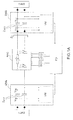
- the Figure 1B shows the schematic of a possible embodiment of the RAC impedance matching network.
- This network is reconfigurable for two reasons: on the one hand, a set of controlled switches INT A , INT B , INT C makes it possible to modify the topology; on the other hand, it comprises a set of reactive elements C A , C B , C c , L A , L B , L C at least some of which (at least one, preferably several) variable reactance.
- the network has a generally "Pi" configuration with a central branch and two lateral branches or legs.
- each of these branches can be capacitive, inductive or constitute a parallel LC circuit; in addition, the legs can be disconnected.
- the impedance matching network it is possible to act on the switches to configure the impedance matching network to take a topology selected from the following: Pi topology with capacitive legs and inductive central branch; Pi topology with inductive legs and capacitive central branch; simple parallel RC circuit connected in series between the first and the second radiofrequency device.
- Step “a” corresponds to the measurement operations performed by the DME and / or DMS device
- step “f” corresponds to the configuration of the RAC network by the DC1 and DC2 devices.
- Step "g” is optional. It consists in iteratively adjusting the impedance values - using the configuration device DC2 driven by the processor PD - so as to optimize the electrical power at the output of the adaptation network, or even the electrical power measured in one. another point in the radio frequency chain.
- the idea underlying this step is that sometimes it may be advantageous to accept a slight impedance mismatch if it is accompanied by a significant reduction in the losses introduced by the adaptation network.
- the use of a device for measuring the power distinct from the measurement device (s) used (s) to achieve the impedance matching is also possible in the case of a transmission chain. This is particularly advantageous if it is desired to perform the current and voltage measurements used for the automatic adaptation of impedance at the input of the adaptation network, and not at its output.
- step “g” can also be implemented when the impedance matching network has a fixed topology (in which case step “d” is executed once and step “e” Is not right). Compared with the process described in the document US 2009/0130991 above, the convergence is faster because the iterative optimization starts from an impedance matching situation, which is already close to optimality.
- steps "b” to “e” and “g” will be described in more detail with reference to the specific case illustrated in FIG. figure 3 , namely a transmission chain with measurement of the current and the output voltage of the impedance matching circuit.
- the generation in other cases, such as that of a reception chain does not pose any particular difficulty.
- Step "b” calculation of the current load impedance.
- the measuring circuit DMS receives the voltage signals V 1S and V 2S defined previously. These voltages are at the carrier frequency f; they are preferably downconverted or baseband-fed by conventional frequency changing circuits using a local oscillator and mixers. Then the voltage levels V 1S and V 2S , brought back to this intermediate frequency or in baseband, are used to calculate the vector current i which crosses the measurement impedance Z MCS and therefore the complex impedance V 1 S / i seen by the amplifier. The phase shifts are retained in the frequency change.
- the module of i is the ratio of the module of V 1S and the module of the impedance Z DMS ; the phase shift of i with respect to the voltage V 1S is an angle ⁇ which represents the argument of the impedance Z m .
- the phase difference between V 1S and V 2S can be calculated for example by multiplying the analog signals V 1S and V 2S , brought back into baseband, and observing the periodic variation of the product of the two signals. This product oscillates between a positive maximum value and a negative minimum value.
- the algebraic sum of these two values is proportional to the cosine of the phase shift and the coefficient of proportionality is the algebraic difference of these two values. Consequently, by relating the sum of the two values to the difference of the two values, we find the cosine of the phase shift from which we draw the phase shift between V 1S and V 2S , from which we deduce the phase difference between V 1S and i.
- phase shift calculation for example by digitizing the two V 1 S and V 2 S signals on a bit, equal to 1 when the signal is positive and 0 when it is negative.
- the time shift of the bit pulse trains 1 resulting from the digitization of V 1S with respect to the same pulse trains corresponding to the digitization of V 2S , represents the phase shift between V 1S and V 2S .
- the sign of the phase shift is identified by observing the rising edges of the signals thus digitized on one bit; this can be done by a flip-flop D which receives on one signal input one of the voltages V 1S or V 2S and on a clock input the other of these voltages, and which carries back to its output the state of the signal input at the time of a rising edge on the clock input.
- Step "c” calculation of the current impedance of the antenna.
- Step "d” calculation of modified values for the reactances of the adaptation network.
- Step "e” calculation of power efficiency (or equivalent loss).
- the figure 5 shows an equivalent diagram of the impedance matching circuit of the Figure 1B in its "Pi" configuration with inductive central branch and capacitive legs, placed in the radiofrequency chain of the figure 3 .
- the equivalent resistance R 1 represents the combined effect of the output impedance of the power amplifier PA, assumed to be known and purely resistive, and the parasitic resistance of the capacitor C A ; C 1 is, in this particular case, equal to C A.
- the equivalent resistance R 2 represents the combined effect of the input impedance of the antenna Z ant , measured during the step "c" and considered purely resistive, and the parasitic resistance of the capacitors C B and Z DMS ; C 2 is an equivalent capacity accounting for the capacitive effects due to C B and Z DMS .
- Q C1 , Q C2 , Q L1 , Q L2 of the equivalent elements C 1 , C 2 , L 1 and L 2 can be defined:
- Q VS 1 ⁇ R 1 VS 1
- Q VS 2 ⁇ R 2 VS 2
- the 1 ⁇ The 1 r 1
- the 2 ⁇ The 2 r 2
- the efficiency ⁇ depends on the value of C 1 , C 2 , L 1 and L 2 and therefore of C A , L B and C C ; so, it varies when one adjusts the value of reactance of the RAC adaptation network elements to perform impedance matching. Moreover, the value of the parasitic resistors can also vary during this adjustment.
- Step "g” iterative optimization of the output power of the adaptation network.
- This last step which is optional, consists in iteratively varying the reactances of the RAC network around the values determined during the step "d", without modifying the topology of the chosen network following the step "f", in order to maximize the power transmitted to the antenna and measured using the DMS device.
- the optimization is done by acting on the actual circuit and measuring the power effectively transmitted, and not on the basis of calculations using a model of the circuit. This iterative optimization makes it possible to take into account the fact that a slight impedance mismatch can be more than compensated by a reduction in the level of losses in the matching circuit. It also makes it possible to correct the inaccuracies inherent in the models used to determine the configuration carrying out the impedance matching.
- the first and the second radio frequency device may not be an antenna and a power amplifier or low noise; it is not essential that the radio frequency chain is a transmission or reception chain.
- the impedance matching network may not have a "Pi" topology but, for example, a "Te" topology or a more complex type.
- the optimization of the configuration of the adaptation network taking into account both the impedance matching and the losses can be done differently than according to the method of the figure 2 ; an alternative may be to test a plurality of configurations - defined by a topology and a set of reactance values of the reactive elements of the network - sampling the configuration space, then to choose the optimal configuration, that is to say maximizing at least one performance criterion such as the power transferred through the adaptation network.
Landscapes
- Engineering & Computer Science (AREA)
- Computer Networks & Wireless Communication (AREA)
- Signal Processing (AREA)
- Transmitters (AREA)
- Amplifiers (AREA)
- Measurement Of Resistance Or Impedance (AREA)
Abstract
Procédé d'adaptation automatique d'impédance d'une chaîne à radiofréquence comprenant : un réseau d'adaptation d'impédance (RAC) ayant une entrée et une sortie, un premier dispositif à radiofréquence (DFR1) connecté à ladite entrée et un deuxième dispositif à radiofréquence (DRF2) connecté à ladite sortie, ledit réseau d'adaptation d'impédance présentant une topologie reconfigurable et comprenant une pluralité d'éléments réactifs (C A , LA, C B , L B , C C , L C ) dont au moins un présente une réactance variable, le procédé comprenant le choix de la configuration du réseau d'adaptation d'impédance permettant de réaliser une adaptation d'impédance tout en minimisant les pertes. Module d'adaptation automatique d'impédance pour la mise en oeuvre d'un tel procédé. Chaînes d'émission et de réception à radiofréquence comprenant un tel module.A method for automatic impedance matching of a radio frequency chain comprising: an impedance matching network (RAC) having an input and an output, a first radio frequency device (DFR1) connected to said input and a second device radio frequency (DRF2) connected to said output, said impedance matching network having a reconfigurable topology and comprising a plurality of reactive elements (CA, LA, CB, LB, CC, LC) of which at least one has a reactance variable, the method comprising choosing the configuration of the impedance matching network to achieve impedance matching while minimizing losses. Automatic impedance adaptation module for implementing such a method. Radiofrequency transmit and receive channels comprising such a module.
Description
L'invention porte sur un procédé d'adaptation automatique d'impédance d'une chaîne à radiofréquence, telle qu'une chaîne d'émission ou de réception à radiofréquence, et plus spécifiquement sur un procédé d'adaptation automatique d'antenne. L'invention porte également sur un module d'adaptation automatique d'impédance permettant la mise en oeuvre d'un tel procédé, ainsi que sur des chaînes d'émission et de réception à radiofréquence comprenant un tel module d'adaptation automatique d'impédance.The invention relates to a method for automatic impedance matching of a radio frequency chain, such as a radiofrequency transmit or receive string, and more specifically to an automatic antenna matching method. The invention also relates to an automatic impedance adaptation module enabling the implementation of such a method, as well as radiofrequency transmission and reception strings comprising such an automatic impedance matching module. .
Dans certaines applications de transmission d'informations en radiofréquence, on a constaté que l'antenne d'émission ou de réception pouvait avoir une impédance dépendant fortement de conditions extérieures à l'antenne, et dépendant notamment du milieu dans lequel l'antenne est placée.In certain radiofrequency information transmission applications, it has been found that the transmitting or receiving antenna can have an impedance strongly dependent on conditions outside the antenna, and depending in particular on the medium in which the antenna is placed. .
Par exemple, dans la télémétrie médicale, on peut être amené à introduire l'antenne dans une sonde placée dans le corps humain, et l'impédance dépend alors fortement du milieu biologique dans lequel l'antenne se trouve. Elle dépend des propriétés électriques (conductivité, constante diélectrique) des tissus environnants (muscles, graisse) ou du milieu liquide (sang, autres liquides) dans lequel l'antenne peut être immergée.For example, in medical telemetry, it may be necessary to introduce the antenna into a probe placed in the human body, and the impedance then strongly depends on the biological medium in which the antenna is located. It depends on the electrical properties (conductivity, dielectric constant) of surrounding tissues (muscles, fat) or liquid medium (blood, other liquids) in which the antenna can be immersed.
Même dans des applications plus conventionnelles de transmission radiofréquence (téléphonie mobile, etc.) l'impédance de l'antenne peut varier.Even in more conventional applications of radio frequency transmission (mobile telephony, etc.) the antenna impedance may vary.
De manière générale, les variations d'impédance d'antenne sont particulièrement sensibles pour des antennes de très petites dimensions ayant un fort coefficient de qualité, utilisées dans les applications à fortes contraintes de miniaturisation.In general, the variations of antenna impedance are particularly sensitive for very small antennas having a high quality coefficient, used in applications with high miniaturization constraints.
Ces variations d'impédance peuvent entraîner des pertes dites pertes de désadaptation : ces pertes résultent de ce que la chaîne d'émission qui alimente l'antenne, ou la chaîne de réception qui reçoit un signal de l'antenne, est en général conçue pour avoir des performances optimales lorsqu'elle est chargée (en sortie pour la chaîne d'émission ou en entrée pour la chaîne de réception) par une impédance nominale bien déterminée ; elle a des performances dégradées lorsqu'elle est chargée par une impédance différente de sa valeur nominale. Les pertes de désadaptation peuvent aller jusqu'à 40 dB.These variations in impedance can lead to losses called mismatch losses: these losses result from the fact that the transmission channel that feeds the antenna, or the reception chain that receives a signal of the antenna is generally designed to have optimal performance when it is loaded (at the output for the transmission chain or at the input for the reception chain) by a well-defined nominal impedance; it has degraded performance when it is loaded by an impedance different from its nominal value. Mismatch losses can be up to 40 dB.
C'est pourquoi il est connu d'interposer, entre la sortie d'un amplificateur de puissance et l'antenne d'une chaîne d'émission, un réseau d'adaptation d'impédance, en anglais « matching network », qui fait que la chaîne d'émission voit une impédance différente de celle de l'antenne et de préférence égale à la valeur nominale pour laquelle elle a été conçue, par exemple 100 ohms ou 500 ohms. Le réseau d'adaptation est accordable, c'est-à-dire que ses éléments, capacitifs et/ou inductifs, ont des valeurs ajustables pour tenir compte des conditions d'environnement de l'antenne de telle sorte que l'adaptation soit la meilleure possible quelles que soient les circonstances. De même, il est connu d'interposer un tel réseau d'adaptation d'impédance entre l'antenne d'une chaîne de réception et l'entrée d'un amplificateur à bas bruit.This is why it is known to interpose, between the output of a power amplifier and the antenna of a transmission channel, an impedance matching network, in English "matching network", which makes that the transmission chain sees an impedance different from that of the antenna and preferably equal to the nominal value for which it was designed, for example 100 ohms or 500 ohms. The adaptation network is tunable, that is to say that its elements, capacitive and / or inductive, have adjustable values to take into account the environmental conditions of the antenna so that the adaptation is the best possible under any circumstances. Similarly, it is known to interpose such an impedance matching network between the antenna of a reception chain and the input of a low noise amplifier.
Plusieurs techniques ont été proposées pour accorder de manière automatique un tel réseau d'adaptation, de manière à suivre, par exemple, des variations de l'impédance d'antenne induites par des conditions extérieures.Several techniques have been proposed for automatically tuning such an adaptation network, so as to follow, for example, variations in the antenna impedance induced by external conditions.
Le document
Le document
Les documents
Le document
Un inconvénient des procédés d'adaptation automatique selon l'art antérieur est de ne pas prendre en compte les pertes introduites par le réseau d'adaptation d'impédance. Ces pertes trouvent leur origine dans le comportement non-idéal des éléments réactifs (condensateurs et selfs), dont l'impédance présente une composante résistive non nulle, et dans certains cas peuvent être supérieures au gain d'efficacité procuré par l'adaptation d'impédance.A disadvantage of the automatic adaptation methods according to the prior art is that it does not take into account the losses introduced by the impedance matching network. These losses have their origin in the non-ideal behavior of the reactive elements (capacitors and chokes), whose impedance has a non-zero resistive component, and in some cases cases may be greater than the efficiency gain provided by the impedance matching.
L'invention vise à remédier aux inconvénients précités de l'art antérieur. Plus particulièrement elle vise à procurer un procédé d'adaptation automatique d'impédance permettant une prise en compte des pertes introduites par le réseau d'adaptation d'impédance, tout en étant simple à mettre en oeuvre et convergeant rapidement. Elle vise également à procurer un module d'adaptation d'impédance permettant la mise en oeuvre d'un tel procédé.The invention aims to remedy the aforementioned drawbacks of the prior art. More particularly, it aims to provide an automatic impedance matching method allowing the losses introduced by the impedance matching network to be taken into account, while being simple to implement and convergent quickly. It also aims to provide an impedance matching module for implementing such a method.
Conformément à l'invention, ce but est atteint grâce à :
- un réseau d'adaptation présentant, outre des éléments de réactance variable, une topologie reconfigurable ; et
- un processeur configuré ou programmé pour configurer ledit réseau d'adaptation en ajustant les valeurs de réactance desdits éléments et en déterminant sa topologie afin de réaliser une adaptation d'impédance tout en minimisant les pertes.
- an adaptation network having, in addition to variable reactance elements, a reconfigurable topology; and
- a processor configured or programmed to configure said matching network by adjusting the reactance values of said elements and determining its topology to achieve impedance matching while minimizing losses.
Un objet de l'invention est donc un procédé d'adaptation automatique d'impédance d'une chaîne à radiofréquence comprenant : un réseau d'adaptation d'impédance ayant une entrée et une sortie, un premier dispositif à radiofréquence connecté à ladite entrée et un deuxième dispositif à radiofréquence connecté à ladite sortie, ledit réseau d'adaptation d'impédance présentant une topologie reconfigurable et comprenant une pluralité d'éléments réactifs dont au moins un présente une réactance variable, le procédé comprenant :
- la mesure d'au moins un courant et une tension à l'entrée ou à la sortie dudit réseau d'adaptation d'impédance ;
- la détermination, par un processeur de données recevant en entrée les résultats desdites mesures, d'une topologie dudit réseau d'adaptation et d'une valeur de réactance dudit ou de chaque dit élément réactif de manière à optimiser conjointement l'adaptation d'impédance entre ledit premier et ledit deuxième dispositif à radiofréquence et le rendement de puissance dudit réseau d'adaptation ; et
- la configuration dudit réseau d'adaptation d'impédance de telle sorte qu'il prenne ladite topologie et que ledit ou de chaque dit élément réactif présentant une réactance variable prenne ladite valeur de réactance.
- measuring at least one current and a voltage at the input or output of said impedance matching network;
- determining, by a data processor receiving input the results of said measurements, a topology of said matching network and a reactance value of said or each said reactive element so as to jointly optimize the impedance matching between said first and said second radio frequency device and the power efficiency of said matching network; and
- configuring said impedance matching network such that it takes said topology and said or each said reactive element having a variable reactance takes said reactance value.
Selon différents modes de réalisation :
- Le procédé peut comprendre les étapes suivantes :
- a) mesurer au moins un courant et une tension à l'entrée ou à la sortie dudit réseau d'adaptation d'impédance ;
- b) calculer une impédance complexe Zm, définie par le rapport entre la tension et le courant mesurés en tenant compte de leur déphasage et représentant une impédance de charge dudit premier dispositif à radiofréquence ou une impédance d'entrée dudit deuxième dispositif à radiofréquence, selon que les mesures de l'étape a) aient été effectuées à l'entrée ou à la sortie dudit réseau d'adaptation d'impédance ;
- c) à partir de ladite impédance complexe Zm, de la topologie et des valeurs actuelles connues des éléments réactifs dudit réseau d'adaptation d'impédance, calculer la valeur d'une impédance complexe Zd représentative d'une impédance de sortie dudit premier dispositif à radiofréquence ou d'une impédance d'entrée dudit deuxième dispositif à radiofréquence, selon que les mesures de l'étape a) aient été effectuées à l'entrée ou à la sortie dudit réseau d'adaptation d'impédance ;
- d) pour une pluralité de topologies possibles dudit réseau d'adaptation d'impédance, calculer des nouvelles valeurs de réactance dudit ou de chaque dit élément réactif présentant une réactance variable, de telle sorte que ladite impédance de charge dudit premier dispositif à radiofréquence ou ladite impédance d'entrée dudit deuxième dispositif à radiofréquence prenne une valeur aussi proche que possible d'une valeur nominale prédéfinie ;
- e) choisir, parmi lesdites topologies dudit réseau d'adaptation d'impédance, celle qui minimise les pertes lorsque la réactance dudit ou de chaque dit élément réactif présentant une réactance variable prend la valeur calculée à l'étape d) ; et
- f) configurer le réseau d'adaptation d'impédance de telle sorte qu'il prenne la topologie déterminée à l'étape e) et que la réactance dudit ou de chaque dit élément réactif présentant une réactance variable prenne la valeur calculée à l'étape d).
- Plus particulièrement, les mesures de l'étape a) peuvent être effectuées à la sortie dudit réseau d'adaptation d'impédance, le procédé comprenant également l'étape suivante, mise en oeuvre après ladite étape f) :
- g) calculer la puissance électrique en sorite dudit réseau d'adaptation d'impédance à partir de la tension et du courant mesurés, et ajuster itérativement la réactance dudit ou de chaque dit élément réactif présentant une réactance variable de manière à maximiser ladite puissance électrique.
- Ledit premier dispositif à radiofréquence peut être ou comprendre un amplificateur de puissance et ledit deuxième dispositif à radiofréquence peut être ou comprendre une antenne.
- Ledit premier dispositif à radiofréquence peut être ou comprendre une antenne et ledit deuxième dispositif à radiofréquence peut être ou comprendre un amplificateur à bas bruit.
- Ledit premier dispositif à radiofréquence peut être ou comprendre une antenne et ledit deuxième dispositif à radiofréquence peut être ou comprendre un amplificateur à bas bruit, le procédé comprenant également l'étape suivante, mise en oeuvre après ladite étape f) :
- g') mesurer la puissance électrique en sorite dudit amplificateur à bas bruit, et ajuster itérativement la réactance dudit ou de chaque dit élément réactif présentant une réactance variable de manière à maximiser ladite puissance électrique.
- The method may comprise the following steps:
- a) measuring at least one current and a voltage at the input or output of said impedance matching network;
- b) calculating a complex impedance Z m , defined by the ratio between the voltage and the current measured taking into account their phase shift and representing a load impedance of said first radio frequency device or an input impedance of said second radio frequency device, according to the measurements of step a) have been performed at the input or output of said impedance matching network;
- c) from said complex impedance Z m , the topology and the current known values of the reactive elements of said impedance matching network, calculating the value of a complex impedance Z d representative of an output impedance of said first a radio frequency device or input impedance of said second radio frequency device, depending on whether the measurements of step a) have been performed at the input or output of said impedance matching network;
- d) for a plurality of possible topologies of said impedance matching network, computing new reactance values of said or each said reactive element having a variable reactance, such that said load impedance of said first radio frequency device or said the input impedance of said second radio frequency device takes a value as close as possible to a predefined nominal value;
- e) selecting, from among said topologies of said impedance matching network, that which minimizes losses when the reactance said or each said reactive element having a variable reactance takes the value calculated in step d); and
- f) configuring the impedance matching network so that it takes the topology determined in step e) and the reactance of said or each said reactive element having a variable reactance takes the value calculated in step d).
- More particularly, the measurements of step a) can be performed at the output of said impedance matching network, the method also comprising the following step, implemented after said step f):
- g) calculating the electrical power output of said impedance matching network from the measured voltage and current, and iteratively adjusting the reactance of said or each said reactive element having a variable reactance so as to maximize said electrical power.
- The first radio frequency device may or may comprise a power amplifier and the second radio frequency device may be or include an antenna.
- The first radio frequency device may be or include an antenna and the second radio frequency device may be or include a low noise amplifier.
- Said first radiofrequency device may be or comprise an antenna and said second radio frequency device may be or comprise a low noise amplifier, the method also comprising the following step, implemented after said step f):
- g ') measuring the electrical power output of said low noise amplifier, and iteratively adjusting the reactance of said or each said reactive element having a variable reactance so as to maximize said electrical power.
Un autre objet de l'invention est un module d'adaptation automatique d'impédance destiné à être agencé entre un premier dispositif à radiofréquence et un deuxième dispositif à radiofréquence, ledit module comprenant : un réseau d'adaptation d'impédance ayant une entrée destinée à être relié audit premier dispositif à radiofréquence et une sortie destinée à être reliée audit deuxième dispositif à radiofréquence, ledit réseau d'adaptation d'impédance comprenant une pluralité d'éléments réactifs dont au moins un présente une réactance variable ; un dispositif de mesure de courant et de tension, agencé pour mesurer un courant et une tension à l'entrée ou à la sortie dudit réseau d'adaptation d'impédance ; au moins un premier dispositif de configuration dudit réseau d'adaptation d'impédance, apte à modifier la réactance dudit ou de chaque dit élément réactif présentant une réactance variable ; et un processeur de données configuré pour recevoir en entrée des mesures de courant et de tension en provenance dudit dispositif de mesure et pour fournir en sortie des signaux de pilotage dudit ou desdits premiers dispositifs de configuration ; caractérisé en ce que : ledit réseau d'adaptation d'impédance présente une topologie reconfigurable ; le module comprend également au moins un deuxième dispositif de configuration dudit réseau d'adaptation d'impédance, apte à modifier sa topologie ; ledit processeur de données est configuré pour déterminer une topologie dudit réseau d'adaptation et une valeur de réactance dudit ou de chaque dit élément réactif de manière à optimiser conjointement l'adaptation d'impédance entre ledit premier et ledit deuxième dispositif à radiofréquence et le rendement de puissance dudit réseau d'adaptation, et pour générer des signaux de pilotage desdits premiers et deuxièmes dispositifs de configuration adaptés pour que lesdits dispositifs configurent le réseau d'adaptation d'impédance de telle sorte qu'il prenne ladite topologie et que ledit ou de chaque dit élément réactif présentant une réactance variable prenne ladite valeur.Another object of the invention is an automatic impedance matching module intended to be arranged between a first radiofrequency device and a second radio frequency device, said module comprising: an impedance matching network having an input for connection to said first radio frequency device and an output for connection to said second radio frequency device, said impedance matching network comprising a plurality of reactive elements at least one of which has a variable reactance; a current and voltage measuring device arranged to measure a current and a voltage at the input or output of said impedance matching network; at least one first configuration device of said impedance matching network, adapted to modify the reactance of said or each said reactive element having a variable reactance; and a data processor configured to receive input current and voltage measurements from said measurement device and to output control signals from said one or more first configuration devices; characterized in that: said impedance matching network has a reconfigurable topology; the module also comprises at least a second configuration device of said impedance matching network, able to modify its topology; said data processor is configured to determine a topology of said matching network and a reactance value of said or each said reactive element so as to jointly optimize the impedance matching between said first and said second radio frequency device and the performance of said adaptation network, and for generating control signals from said first and second configuration devices adapted for said devices to configure the impedance matching network so that it takes said topology and said each said reactive element having a variable reactance takes said value.
Selon différents modes de réalisation :
- Ledit processeur de données peut être configuré pour :
- calculer une impédance complexe Zm, définie par le rapport entre la tension et le courant mesurés par ledit dispositif de mesure en tenant compte de leur déphasage et représentant une impédance de charge dudit premier dispositif à radiofréquence ou une impédance d'entrée dudit deuxième dispositif à radiofréquence, selon que ledit dispositif de mesure soit agencé pour effectuer des mesures à l'entrée ou à la sortie dudit réseau d'adaptation d'impédance ;
- à partir de ladite impédance complexe Zm, de la topologie et des valeurs actuelles connues des éléments réactifs dudit réseau d'adaptation d'impédance, calculer la valeur d'une impédance complexe Zd représentative d'une impédance de sortie dudit premier dispositif à radiofréquence ou d'une impédance d'entrée dudit deuxième dispositif à radiofréquence, selon que ledit dispositif de mesure soit agencé pour effectuer des mesures à l'entrée ou
- à la sortie dudit réseau d'adaptation d'impédance ; pour une pluralité de topologies possibles dudit réseau d'adaptation d'impédance, calculer des nouvelles valeurs de réactance dudit ou de chaque dit élément réactif présentant une réactance variable, de telle sorte que ladite impédance de charge dudit premier dispositif à radiofréquence ou ladite impédance d'entrée dudit deuxième dispositif à radiofréquence prenne une valeur aussi proche que possible d'une valeur nominale prédéfinie ; choisir, parmi lesdites topologies dudit réseau d'adaptation d'impédance, celle qui minimise les pertes lorsque la réactance dudit ou de chaque dit élément réactif présentant une réactance variable prend la valeur calculée ; générer des signaux de pilotage desdits premiers et deuxièmes dispositifs de configuration adaptés pour que lesdits dispositifs configurent le réseau d'adaptation d'impédance de telle sorte qu'il prenne la topologie choisie et que ledit ou de chaque dit élément réactif présentant une réactance variable prenne la valeur calculée.
- Ledit processeur de données peut être également configuré pour recevoir en entrée une mesure de puissance électrique, ou des données permettant de calculer une puissance électrique, et pour générer des signaux de pilotage dudit ou desdits premiers dispositifs de configuration adaptés pour que lesdits dispositifs ajustent itérativement la réactance dudit ou de chaque dit élément réactif présentant une réactance variable de manière à maximiser ladite puissance électrique.
- En outre, ledit processeur de données peut être configuré pour calculer ladite puissance électrique à partir des mesures de courant et de tension en provenance dudit dispositif de mesure.
- En variante, ledit module d'adaptation d'impédance peut comprendre également un dispositif de mesure de puissance agencé pour mesurer une puissance électrique de sortie dudit deuxième dispositif à radiofréquence et pour fournir un résultat de mesure audit processeur de données.
- Said data processor may be configured to:
- calculating a complex impedance Z m , defined by the ratio between the voltage and the current measured by said measuring device taking into account their phase shift and representing a load impedance of said first radiofrequency device or an input impedance of said second device to radio frequency, according to whether said measuring device is arranged to make measurements at the input or at the output of said impedance matching network;
- from said complex impedance Z m , the topology and the current known values of the reactive elements of said impedance matching network, calculating the value of a complex impedance Z d representative of an output impedance of said first device to radio frequency or an input impedance of said second radio frequency device, according to whether said measuring device is arranged to perform measurements at the input or
- at the output of said impedance matching network; for a plurality of possible topologies of said impedance matching network, computing new reactance values of said or each said reactive element having a variable reactance, such that said load impedance of said first radio frequency device or said impedance of the input of said second radio frequency device takes a value as close as possible to a predefined nominal value; selecting, from among said topologies of said impedance matching network, that which minimizes losses when the reactance of said or each said reactive element having a variable reactance takes the calculated value; generating control signals from said first and second configuration devices adapted for said devices to configure the impedance matching network so that it takes the selected topology and that said or each said reactive element having a variable reactance takes the calculated value.
- Said data processor may also be configured to receive as input an electrical power measurement, or data for calculating electrical power, and to generate control signals from said one or more first configuration devices adapted for said devices to iteratively adjust the reactance of said or each said reactive element having a variable reactance so as to maximize said electrical power.
- In addition, said data processor may be configured to calculate said electrical power from the current and voltage measurements from said measurement device.
- Alternatively, said impedance matching module may also include a power meter arranged to measure an output electrical power of said second radio frequency device and to provide a measurement result to said data processor.
Encore un autre objet de l'invention est une chaîne d'émission radiofréquence comprenant un amplificateur de puissance, une antenne et un tel module d'adaptation automatique d'impédance connecté entre une sortie dudit amplificateur de puissance et un port d'entrée de ladite antenne.Yet another object of the invention is a radiofrequency transmission chain comprising a power amplifier, an antenna and such an automatic impedance matching module connected between an output of said power amplifier and an input port of said antenna.
Encore un autre objet de l'invention est une chaîne de réception radiofréquence comprenant une antenne, un amplificateur à bas bruit et un tel module d'adaptation automatique d'impédance connecté entre un port de sortie de ladite antenne et une entrée dudit amplificateur à bas bruit.Yet another object of the invention is a radio frequency reception chain comprising an antenna, a low-noise amplifier and such an automatic impedance matching module connected between an output port of said antenna and an input of said low-level amplifier. noise.
On entend par « radiofréquence » toute fréquence comprise entre 3 kHz et 300 GHz.Radio frequency means any frequency between 3 kHz and 300 GHz.
On entend par « amplificateur de puissance » un amplificateur dont une sortie est reliée ou destinée à être reliée, de manière directe ou indirecte, à une antenne émettrice.The term "power amplifier" means an amplifier whose output is connected to or intended to be connected, directly or indirectly, to an emitter antenna.
On entend par « amplificateur à bas bruit » un amplificateur dont une entrée est reliée ou destinée à être reliée, de manière directe ou indirecte, à une antenne réceptrice.The term "low-noise amplifier" means an amplifier whose input is connected to or intended to be connected, directly or indirectly, to a receiving antenna.
On entend par « élément réactif » un composant électrique dont l'impédance présente, à au moins une fréquence dans le domaine radiofréquence, une composante réactive (capacitive ou inductive) supérieure ou égale - et de préférence supérieure d'un facteur 10 ou plus - à sa composante résistive."Reactive element" means an electrical component whose impedance has, at at least one frequency in the radiofrequency domain, a reactive component (capacitive or inductive) greater than or equal to - and preferably greater by a factor of 10 or more - its resistive component.
La « topologie » d'un réseau électrique est définie par l'ensemble des éléments qui le composent (condensateurs, selfs, résistances...) et leur interconnexion, en faisant abstraction de la valeur de leur résistance, inductance ou capacité. Il est entendu que plusieurs éléments d'un même type connectés en série ou en parallèle sont considérés comme constituant un seul élément. Ainsi on ne change pas de topologie en remplaçant, par exemple, un condensateur unique par deux condensateurs connectés en parallèle.The "topology" of an electrical network is defined by the set of elements that make it up (capacitors, chokes, resistances, etc.) and their interconnection, ignoring the value of their resistance, inductance or capacity. It is understood that several elements of the same type connected in series or in parallel are considered as constituting a single element. Thus one does not change topology by replacing, for example, a single capacitor by two capacitors connected in parallel.
On considérera dans la suite que les signaux dans le réseau d'adaptation présentent une fréquence unique f=2πω, ce qui permet de caractériser un élément capacitif ou inductif (élément réactif) par une valeur de réactance. Cette approximation est généralement satisfaisante dans le domaine des radiofréquences.It will be considered in the following that the signals in the matching network have a unique frequency f = 2πω, which makes it possible to characterize a capacitive or inductive element (reactive element) by a reactance value. This approximation is generally satisfactory in the field of radio frequencies.
D'autres caractéristiques, détails et avantages de l'invention ressortiront à la lecture de la description faite en référence aux dessins annexés donnés à titre d'exemple et qui représentent, respectivement :
- La
figure 1A , le schéma fonctionnel d'un module d'adaptation automatique d'impédance selon un mode de réalisation de l'invention ; - La
figure 1B , le schéma électrique du réseau d'adaptation d'impédance du module de lafigure 1A ; - La
figure 2 , l'ordinogramme d'un procédé d'adaptation automatique d'impédance selon un mode de réalisation de l'invention ; - Les
figures 3 et 4 , respectivement, les schémas fonctionnels d'une chaîne d'émission à radiofréquence et d'une chaîne de réception à radiofréquence selon des modes de réalisation respectifs de l'invention ; et - La
figure 5 , le schéma électrique équivalent d'un réseau d'adaptation d'impédance en « Pi », utilisé pour calculer son rendement de puissance.
- The
Figure 1A , the block diagram of an automatic impedance matching module according to an embodiment of the invention; - The
Figure 1B , the electrical diagram of the impedance matching network of the module of theFigure 1A ; - The
figure 2 the flow chart of an automatic impedance matching method according to an embodiment of the invention; - The
Figures 3 and 4 respectively the block diagrams of a radio frequency transmission chain and a radio frequency receiver chain according to respective embodiments of the invention; and - The
figure 5 , the equivalent electrical diagram of an impedance matching network in "Pi", used to calculate its power efficiency.
La
Dans la suite on considérera toujours que la puissance électrique se propage de DRF1 vers DRF, de telle sorte que le dispositif de mesure DME est agencé au niveau de l'entrée du réseau d'adaptation d'impédance et le dispositif de mesure DMS est agencé au niveau de la sortie de ce dernier.In the following, we will always consider that the electrical power propagates from DRF1 to DRF, so that the measuring device DME is arranged at the input of the impedance matching network and the measuring device DMS is arranged. at the output of the latter.
Les dispositifs de mesure DME, DMS permettent de mesurer la tension et le courant d'entrée et de sortie du réseau d'adaptation, respectivement. Ces dispositifs peuvent notamment être du type décrit dans le document
- une impédance ZMCE, ZMCS connecté en série ;
- un dispositif VM permettant de mesurer la tension en amont et en aval de cette impédance.
- an impedance Z MCE , Z MCS connected in series;
- a VM device for measuring the voltage upstream and downstream of this impedance.
De préférence, les impédances de mesure ZMCE, ZMCS sont réactive, et de manière encore préférée, capacitives. Dans l'exemple de la
Chaque dispositif VM est essentiellement constitué par un circuit de changement de fréquence classique et un convertisseur analogique-numérique. En effet, les tensions aux bornes des impédances de mesure sont des signaux électriques à la fréquence porteuse f. Pour réduire la consommation électrique, et améliorer la précision de calcul, il peut être intéressant d'effectuer le calcul d'impédance à basse fréquence. Il est alors prévu une conversion à une fréquence plus basse pour pouvoir faire les calculs qui suivent. On notera que dans certains cas on peut utiliser, pour constituer ce circuit de mesure, des éléments de circuits présents dans les circuits de réception radiofréquence du système. En effet si le système fonctionne en émission et en réception, la partie réception comporte des circuits de changement de fréquence et ces circuits peuvent très bien servir pour effectuer les mesures de tension.Each VM device is essentially constituted by a conventional frequency change circuit and an analog-digital converter. Indeed, the voltages at the terminals of the measurement impedances are electrical signals at the carrier frequency f. To reduce the power consumption, and improve the calculation accuracy, it may be interesting to perform the low frequency impedance calculation. It is then expected a conversion to a lower frequency to be able to make the calculations that follow. It should be noted that in certain cases, circuit elements present in the radiofrequency reception circuits of the system may be used to constitute this measuring circuit. Indeed, if the system operates in transmission and reception, the receiving part has frequency change circuits and these circuits can very well be used to perform the voltage measurements.
La mesure chute de tension V1S-V2S (V2E-V1E) aux bornes de l'impédance ZMCS (ZMCE) permet de déterminer le courant de sortie (d'entrée) du réseau d'adaptation. La tension de sortie (d'entrée) du réseau d'adaptation est mesurée directement par le dispositif VM.The voltage drop measurement V 1S -V 2S (V 2E -V 1E ) across the impedance Z MCS (Z MCE ) is used to determine the output current (input) of the adaptation network. The output (input) voltage of the adaptation network is measured directly by the device VM.
En calculant le rapport et le déphasage entre le courant et la tension de sortie du réseau d'adaptation, mesurés par le dispositif ZMCS, on peut donc déterminer une impédance complexe Zm qui représente l'impédance de sortie du réseau d'adaptation. De même, en calculant le rapport et le déphasage entre le courant et la tension d'entrée du réseau d'adaptation, mesurés par le dispositif ZMCS, on peut déterminer une impédance complexe qui représente l'impédance d'entrée du réseau d'adaptation, et donc l'impédance de charge du dispositif à radiofréquence DRF1 (l'amplificateur, dans une chaîne d'émission).By calculating the ratio and the phase shift between the current and the output voltage of the matching network, measured by the Z MCS device, it is therefore possible to determine a complex impedance Z m which represents the output impedance of the matching network. Similarly, by calculating the ratio and the phase shift between the current and the input voltage of the matching network, measured by the Z MCS device, a complex impedance can be determined which represents the input impedance of the grating. adaptation, and therefore the load impedance of radio frequency device DRF1 (the amplifier, in a transmission chain).
La
Dans l'exemple de la
Un premier dispositif de configuration DC1 pilote les interrupteurs INTA, INTB, INTC, déterminant ainsi la topologie du réseau d'adaptation d'impédance RAC. Un deuxième dispositif de configuration DC2 agit - électriquement et/ou mécaniquement - sur les éléments réactifs CA, CB, Cc, LA, LB, LC pour modifier leur réactance. Ces dispositifs de configuration sont à leur tour pilotés par le processeur de données PD, voire ils sont intégrés dans ce dernier. Par exemple, le premier dispositif de configuration peut comprendre des circuits électronique de pilotage des interrupteurs INTA, INTB, INTC et le deuxième dispositif de configuration des générateurs de tension permettant de varier la capacité de diodes à capacité variable et des générateurs de courant permettant de varier l'inductance de selfs présentant un noyau saturable ; il existe également des inductances commandées en tension, ainsi que des inductances accordables de type micro-électromécanique (MEMS), voir par exemple :
-
Casha, O. ; Grech, I. ; Micallef, J. ; Gatt, E. ; Morche, D. ; Viala, B.; Michel, J.P. ; Vincent, P. ; de Foucauld, E. : « Utilization of MEMS Tunable Inductors in the design of RF voltage-controlled oscillators », 15th IEEE International Conference on Electronics, Circuits and Systems, 2008. ICECS 2008 -
L. Collot, J. Lintignat, B. Viala, D. Morche, J-P. Michel, B. Barelaud, B. Jarry « Reconfigurable Filtering Differential Low Noise Amplifier Using MEMS Tunable Inductor » Proceedings of the 40th European Microwave Conférence, 2010 , Pages: 826 - 829
-
Casha, O .; Grech, I.; Micallef, J.; Gatt, E.; Morche, D.; Viala, B .; Michel, JP; Vincent, P.; of Foucauld, E.: "Utilization of MEMS Tunable Inductors in the design of RF voltage-controlled oscillators", 15th IEEE International Conference on Electronics, Circuits and Systems, 2008. ICECS 2008 -
L. Collot, J. Lintignat, B. Viala, D. Morche, JP. Michel, B. Barelaud, B. Jarry "Reconfigurable Filtering Differential Low Noise Amplifier Using MEMS Tunable Inductor" Proceedings of the 40th European Microwave Conference, 2010, Pages: 826 - 829
Le processeur de données PD est typiquement un microprocesseur programmé de manière opportune, mais il peut également s'agir d'un circuit numérique configuré de manière matérielle, ou d'une combinaison des deux. Ce processeur réalise les opérations suivantes :
- A partir des mesures de tension et de courant réalisées par le dispositif de mesure DME et/ou DMS, il détermine l'impédance d'entrée et/ou de sortie du réseau d'adaptation d'impédance.
- A partir de l'impédance d'entrée et/ou de sortie du réseau d'adaptation, de ce dernier (topologie et valeur des réactances), il détermine la valeur de l'impédance du dispositif DRF1 ou du dispositif DRF2. Typiquement, dans le cas d'une chaîne d'émission ou de réception à radiofréquence, il s'agira de déterminer l'impédance de l'antenne - correspondant à DRF2 dans une chaîne d'émission et à DRF1 dans une chaîne de réception.
- Il détermine la valeur que doivent prendre les réactances des éléments variables du réseau d'adaptation d'impédance pour réaliser une adaptation d'impédance de la chaîne à radiofréquence. Typiquement, dans une chaîne d'émission il s'agira de faire en sorte que l'impédance de charge de l'amplificateur de puissance (DRF1) soit égale, ou aussi proche que possible, d'une impédance optimale prédéfinie (généralement, l'impédance de sortie dudit amplificateur). De même, dans le cas d'une chaîne de réception il s'agira de faire en sorte que l'impédance à l'entrée de l'amplificateur à bas bruit (DRF2) soit égale, ou aussi proche que possible, d'une impédance optimale prédéfinie (généralement, l'impédance d'entrée dudit amplificateur). Ce calcul est répété pour chaque topologie possible (ou au moins pour un ensemble prédéfini de topologies possibles) du réseau RAC. On obtient ainsi une pluralité de configurations admissibles du réseau RAC, présentant des topologies différentes et permettant toutes de réaliser une adaptation d'impédance.
- Parmi ces configurations admissibles, il sélectionne celle qui présente le meilleur rendement de puissance, et donc les plus faibles pertes. Pour cela, il doit disposer d'une caractérisation des différents éléments réactifs du réseau d'adaptation. Puis, il commande les dispositifs de configuration DC1, DC2 du réseau d'adaptation en conséquence.
- From the voltage and current measurements made by the measuring device DME and / or DMS, it determines the input and / or output impedance of the impedance matching network.
- From the input and / or output impedance of the adaptation network, from the latter (topology and value of the reactances), it determines the value of the impedance of the device DRF1 or of the device DRF2. Typically, in the case of a radiofrequency transmission or reception string, it will be necessary to determine the impedance of the antenna - corresponding to DRF2 in a transmission chain and to DRF1 in a reception chain.
- It determines the value that the reactances of the variable elements of the impedance matching network must take to realize an impedance matching of the radio frequency chain. Typically, in a transmission chain it will be necessary to ensure that the load impedance of the power amplifier (DRF1) is equal to, or as close as possible to, a predefined optimum impedance (generally output impedance of said amplifier). Similarly, in the case of a reception chain it will be necessary to ensure that the impedance at the input of the low noise amplifier (DRF2) is equal to, or as close as possible to, a predefined optimal impedance (generally, the input impedance of said amplifier). This calculation is repeated for each possible topology (or at least for a predefined set of possible topologies) of the RAC network. We obtain a plurality of allowable configurations of the RAC network, having different topologies and all allowing impedance matching.
- Among these allowable configurations, it selects the one with the best power output, and therefore the lowest losses. For this, it must have a characterization of the different reactive elements of the adaptation network. Then, it controls the configuration devices DC1, DC2 of the adaptation network accordingly.
Ces différentes opérations correspondent aux étapes « b », « c », « d » et « e » de l'ordinogramme de la
L'étape « g » est optionnelle. Elle consiste à ajuster de manière itérative les valeurs d'impédance - à l'aide du dispositif de configuration DC2 piloté par le processeur PD - de manière à optimiser la puissance électrique en sortie du réseau d'adaptation, voire la puissance électrique mesurée en un autre point de la chaîne à radiofréquence. L'idée qui sous-tend cette étape est que parfois il peut être avantageux d'accepter une légère désadaptation d'impédance si elle s'accompagne d'une réduction significative des pertes introduites par le réseau d'adaptation.Step "g" is optional. It consists in iteratively adjusting the impedance values - using the configuration device DC2 driven by the processor PD - so as to optimize the electrical power at the output of the adaptation network, or even the electrical power measured in one. another point in the radio frequency chain. The idea underlying this step is that sometimes it may be advantageous to accept a slight impedance mismatch if it is accompanied by a significant reduction in the losses introduced by the adaptation network.
Dans le cas d'une chaîne d'émission, il est pertinent de maximiser la puissance en sortie du réseau d'adaptation, qui est fourni à l'antenne ANT ; cette puissance peut être calculée à partir du courant et de la tension de sortie du réseau RAC, mesurés par le dispositif DMS. L'utilisation d'un dispositif de mesure en entrée, DME, n'est pas nécessaire (
Dans le cas d'une chaîne de réception, par contre, il est préférable de maximiser la puissance W en sortie de l'amplificateur à bas bruit ABB, ce qui nécessite un dispositif de mesure dédié DMP, qui peut présenter une structure semblable à celle de DMS et DME. Ce montage est illustré sur la
L'utilisation d'un dispositif de mesure de la puissance distinct du ou des dispositifs de mesure utilisé(s) pour réaliser l'adaptation d'impédance est également possible dans le cas d'une chaîne d'émission. Cela est particulièrement avantageux si on souhaite réaliser les mesures de courant et de tension utilisées pour l'adaptation automatique d'impédance à l'entrée du réseau d'adaptation, et non à sa sortie.The use of a device for measuring the power distinct from the measurement device (s) used (s) to achieve the impedance matching is also possible in the case of a transmission chain. This is particularly advantageous if it is desired to perform the current and voltage measurements used for the automatic adaptation of impedance at the input of the adaptation network, and not at its output.
Il convient de noter que l'étape « g » peut également être mise en oeuvre lorsque le réseau d'adaptation d'impédance présente une topologie fixe (auquel cas l'étape « d » est exécutée une seule fois et l'étape « e » n'a pas raison d'être). Par rapport au procédé décrit dans le document
Dans la suite, la mise en oeuvre des étapes « b » à « e » et « g » sera décrite en plus en détail en référence au cas spécifique illustré sur la
Le circuit de mesure DMS reçoit les signaux de tension V1S et V2S définis précédemment. Ces tensions sont à la fréquence porteuse f ; elles sont de préférence ramenées à une fréquence intermédiaire ou en bande de base par des circuits de changement de fréquence classiques utilisant un oscillateur local et des mélangeurs. Puis les niveaux de tension V1S et V2S, ramenés à cette fréquence intermédiaire ou en bande de base, sont utilisés pour calculer le courant vectoriel i qui traverse l'impédance de mesure ZMCS et donc l'impédance complexe V1S/i vue par l'amplificateur. Les déphasages sont conservés dans le changement de fréquence.The measuring circuit DMS receives the voltage signals V 1S and V 2S defined previously. These voltages are at the carrier frequency f; they are preferably downconverted or baseband-fed by conventional frequency changing circuits using a local oscillator and mixers. Then the voltage levels V 1S and V 2S , brought back to this intermediate frequency or in baseband, are used to calculate the vector current i which crosses the measurement impedance Z MCS and therefore the complex impedance V 1 S / i seen by the amplifier. The phase shifts are retained in the frequency change.
Le module de i est le rapport du module de V1S et du module de l'impédance ZDMS ; le déphasage de i par rapport à la tension V1S est un angle θ qui représente l'argument de l'impédance Zm. Cet angle peut être déterminé à partir du déphasage entre V1S et V2S auquel on soustrait π/2 sachant que le déphasage entre i et (V1S-V2S) est de π/2 puisque, dans le mode de réalisation de la
Le déphasage entre V1S et V2S peut être calculé par exemple en multipliant les signaux analogiques V1S et V2S, ramenés en bande de base, et en observant la variation périodique du produit des deux signaux. Ce produit oscille entre une valeur maximum positive et une valeur minimum négative. La somme algébrique de ces deux valeurs est proportionnelle au cosinus du déphasage et le coefficient de proportionnalité est la différence algébrique de ces deux valeurs. Par conséquent, en faisant le rapport entre la somme des deux valeurs et la différence des deux valeurs on trouve le cosinus du déphasage dont on tire le déphasage entre V1S et V2S, d'où on déduit le déphasage entre V1S et i. D'autres méthodes de calcul numérique du déphasage peuvent être utilisées, par exemple par numérisation des deux signaux V1S et V2S sur un bit, égal à 1 lorsque le signal est positif et à 0 lorsqu'il est négatif. Le décalage temporel des trains d'impulsions de bits 1 résultant de la numérisation de V1S, par rapport aux mêmes trains d'impulsions correspondant à la numérisation de V2S, représente le déphasage entre V1S et V2S. Le signe du déphasage est repéré en observant les fronts de montée des signaux ainsi numérisés sur un bit ; ceci peut se faire par une bascule D qui reçoit sur une entrée de signal l'une des tensions V1S ou V2S et sur une entrée d'horloge l'autre de ces tensions, et qui reporte à sa sortie l'état de l'entrée de signal au moment d'un front de montée sur l'entrée d'horloge.The phase difference between V 1S and V 2S can be calculated for example by multiplying the analog signals V 1S and V 2S , brought back into baseband, and observing the periodic variation of the product of the two signals. This product oscillates between a positive maximum value and a negative minimum value. The algebraic sum of these two values is proportional to the cosine of the phase shift and the coefficient of proportionality is the algebraic difference of these two values. Consequently, by relating the sum of the two values to the difference of the two values, we find the cosine of the phase shift from which we draw the phase shift between V 1S and V 2S , from which we deduce the phase difference between V 1S and i. Other methods of digital phase shift calculation can be used, for example by digitizing the two V 1 S and V 2 S signals on a bit, equal to 1 when the signal is positive and 0 when it is negative. The time shift of the bit pulse trains 1 resulting from the digitization of V 1S , with respect to the same pulse trains corresponding to the digitization of V 2S , represents the phase shift between V 1S and V 2S . The sign of the phase shift is identified by observing the rising edges of the signals thus digitized on one bit; this can be done by a flip-flop D which receives on one signal input one of the voltages V 1S or V 2S and on a clock input the other of these voltages, and which carries back to its output the state of the signal input at the time of a rising edge on the clock input.
Une fois qu'on a l'argument θ de l'impédance Zm, on peut calculer aisément sa partie réelle et sa partie imaginaire.Once we have the argument θ of the impedance Z m , we can easily calculate its real part and its imaginary part.
A partir de cette mesure de Zm, connaissant la configuration du réseau d'adaptation (topologie et valeurs numériques actuelles des capacités et inductances), et également la valeur numérique de la capacité de mesure ZDMS, on peut calculer l'impédance de l'antenne.From this measurement of Z m , knowing the configuration of the adaptation network (topology and current numerical values of the capacitors and inductances), and also the numerical value of the measurement capacity Z DMS , it is possible to calculate the impedance of the 'antenna.
Ce calcul est immédiat, car on a simplement : Zant=ZDMS-ZMCS This calculation is immediate because we simply have: Z ant = Z DMS -Z MCS
Connaissant à la fois l'impédance actuelle de l'antenne Zant et l'impédance équivalente du réseau d'adaptation Zeq, fonction de (CA, CC, LB), ainsi que l'impédance de mesure ZMCS, il s'agit de calculer les valeurs CA, CC LB qu'il faut donner aux éléments variables pour que l'impédance de l'ensemble ZDME, telle qu'elle sera vue aux bornes de l'amplificateur (et donc à l'entrée du réseau d'adaptation) soit égale à la valeur nominale Zopt (généralement, l'impédance de sortie de l'amplificateur) : ZDME=Zopt.Knowing both the current impedance of the antenna Z ant and the equivalent impedance of the adaptation network Zeq, function of (C A , C C , L B ), as well as the measurement impedance Z MCS , it is to calculate the values C A , C C L B that must be given to the variable elements so that the impedance of the set Z DME , as it will be seen at the terminals of the amplifier (and therefore to the input of the matching network) is equal to the nominal value Z opt (generally, the output impedance of the amplifier): Z DME = Z opt .
Pour ce faire on peut avoir recours à des techniques bien connues de l'homme du métier, basées par exemple sur l'utilisation d'un abaque de Smith. Le document
La
A ce point on peut définir les facteurs de qualité QC1, QC2, QL1, QL2 des éléments équivalents C1, C2, L1 et L2 : ![]()
![]()


![]()
![]()
Le rendement en puissance η est alors donné par 
On peut vérifier que la valeur de η ne dépend pas de la façon dont on décompose LB=L1+L2.We can check that the value of η does not depend on how we break down L B = L 1 + L 2 .
On remarque que le rendement η dépend de la valeur de C1, C2, L1 et L2 et donc de CA, LB et CC ; ainsi, il varie lorsqu'on ajuste la valeur de réactance des éléments du réseau d'adaptation RAC pour réaliser une adaptation d'impédance. Par ailleurs, la valeur des résistances parasites peut également varier lors de cet ajustement.Note that the efficiency η depends on the value of C 1 , C 2 , L 1 and L 2 and therefore of C A , L B and C C ; so, it varies when one adjusts the value of reactance of the RAC adaptation network elements to perform impedance matching. Moreover, the value of the parasitic resistors can also vary during this adjustment.
Une méthode générale de calcul de rendement, pouvant être appliquée à une topologie arbitraire, est détaillée dans l'article de
Il est donc possible de calculer la valeur du rendement η pour toutes les configurations du réseau RAC déterminées lors de l'étape « d », puis de choisir celle qui présente la valeur de rendement la plus élevée.It is therefore possible to calculate the value of the efficiency η for all the configurations of the network RAC determined during the step "d", then to choose the one with the highest value of output.
Cette dernière étape, optionnelle, consiste à faire varier itérativement les réactances du réseau RAC autours des valeurs déterminées lors de l'étape « d », sans modifier la topologie du réseau choisie suite à l'étape « f », cela dans le but de maximiser la puissance transmise à l'antenne et mesurée grâce au dispositif DMS. Contrairement aux étapes précédentes, l'optimisation se fait en agissant sur le circuit réel et en mesurant la puissance effectivement transmise, et pas sur la base de calculs utilisant un modèle du circuit. Cette optimisation itérative permet de tenir compte du fait qu'une légère désadaptation d'impédance peut être plus que compensée par une réduction du niveau de pertes dans le circuit d'adaptation. Elle permet aussi de corriger les imprécisions inhérentes aux modèles utilisés pour déterminer la configuration réalisant l'adaptation d'impédance.This last step, which is optional, consists in iteratively varying the reactances of the RAC network around the values determined during the step "d", without modifying the topology of the chosen network following the step "f", in order to maximize the power transmitted to the antenna and measured using the DMS device. Unlike the previous steps, the optimization is done by acting on the actual circuit and measuring the power effectively transmitted, and not on the basis of calculations using a model of the circuit. This iterative optimization makes it possible to take into account the fact that a slight impedance mismatch can be more than compensated by a reduction in the level of losses in the matching circuit. It also makes it possible to correct the inaccuracies inherent in the models used to determine the configuration carrying out the impedance matching.
Cette étape peut être mise en oeuvre comme expliqué dans le document
L'invention a été décrite en référence à un mode de réalisation particulier, mais elle ne s'y limite pas. Par exemple, le premier et le deuxième dispositif à radiofréquence peuvent ne pas être une antenne et un amplificateur de puissance ou à bas bruit ; il n'est d'ailleurs pas indispensable que la chaîne à radiofréquence soit une chaîne d'émission ou de réception. En outre, le réseau d'adaptation d'impédance peut ne pas présenter une topologie en « Pi » mais, par exemple, une topologie en « Te » ou d'un type plus complexe. Par ailleurs, l'optimisation de la configuration du réseau d'adaptation prenant en compte aussi bien l'adaptation d'impédance que les pertes peut se faire autrement que selon le procédé de la
Claims (13)
caractérisé en ce que :
characterized in that
Applications Claiming Priority (1)
| Application Number | Priority Date | Filing Date | Title |
|---|---|---|---|
| FR1460964A FR3028691B1 (en) | 2014-11-13 | 2014-11-13 | METHOD AND MODULE FOR AUTOMATIC IMPEDANCE ADAPTATION, ESPECIALLY FOR A RADIO FREQUENCY TRANSMISSION OR RECEPTION CHAIN |
Publications (2)
| Publication Number | Publication Date |
|---|---|
| EP3021484A1 true EP3021484A1 (en) | 2016-05-18 |
| EP3021484B1 EP3021484B1 (en) | 2021-01-27 |
Family
ID=52824324
Family Applications (1)
| Application Number | Title | Priority Date | Filing Date |
|---|---|---|---|
| EP15191601.2A Active EP3021484B1 (en) | 2014-11-13 | 2015-10-27 | Method and device for automatically adapting impedance, in particular for a channel transmitting or receiving radio frequencies |
Country Status (3)
| Country | Link |
|---|---|
| US (1) | US10666219B2 (en) |
| EP (1) | EP3021484B1 (en) |
| FR (1) | FR3028691B1 (en) |
Families Citing this family (7)
| Publication number | Priority date | Publication date | Assignee | Title |
|---|---|---|---|---|
| WO2017082931A1 (en) * | 2015-11-13 | 2017-05-18 | Halliburton Energy Services, Inc. | Downhole logging tool using resonant cavity antennas with real-time impedance matching |
| US9755679B1 (en) * | 2016-07-08 | 2017-09-05 | Nxp B.V. | Load dependent receiver configuration |
| CN106982076A (en) * | 2017-02-27 | 2017-07-25 | 广州油菜花信息科技有限公司 | A kind of antenna fast matching method |
| CN109450391A (en) * | 2018-09-30 | 2019-03-08 | 深圳市安芯物联科技有限公司 | RF impedance matching process, control device and adaptation and radio-frequency apparatus |
| US11245432B2 (en) * | 2019-03-06 | 2022-02-08 | Skyworks Solutions, Inc. | Radio frequency device with integrated antenna tuner and multiplexer |
| CN116405042B (en) * | 2023-05-31 | 2023-08-22 | 广州博远装备科技有限公司 | Automatic antenna tuning circuit and system |
| CN117459013B (en) * | 2023-12-22 | 2024-04-23 | 深圳新声半导体有限公司 | On-chip impedance matching network, method, radio frequency receiving circuit and transmitting circuit |
Citations (10)
| Publication number | Priority date | Publication date | Assignee | Title |
|---|---|---|---|---|
| US4375051A (en) | 1981-02-19 | 1983-02-22 | The Perkin-Elmer Corporation | Automatic impedance matching between source and load |
| JPH08195684A (en) * | 1995-01-18 | 1996-07-30 | Anritsu Corp | Automatic matching device for antenna |
| US20070194859A1 (en) * | 2006-02-17 | 2007-08-23 | Samsung Electronics Co., Ltd. | System and method for a tunable impedance matching network |
| EP2037576A2 (en) | 2007-09-11 | 2009-03-18 | Commissariat A L'Energie Atomique - CEA | Method of automatically adapting the impedance of a radiofrequency circuit and emission or reception instrumentation with automatic adaptation |
| US20090130991A1 (en) | 2007-11-16 | 2009-05-21 | Ahmadreza Rofougaran | Method and system for lna adjustment to compensate for dynamic impedance matching |
| WO2011026858A1 (en) | 2009-09-07 | 2011-03-10 | Commissariat A L'energie Atomique Et Aux Energies Alternatives | Impedance matching method for a multi-band antenna, and transmission or reception channel having automatic matching |
| US20110227666A1 (en) * | 2010-03-22 | 2011-09-22 | Paratek Microwave, Inc. | Method and apparatus for adapting a variable impedance network |
| EP2509222A1 (en) | 2011-04-07 | 2012-10-10 | Commissariat A L'energie Atomique Et Aux Energies Alternatives | Channel for radio-frequency transmission or reception, with automatic impedance matching and corresponding method |
| EP2509227A1 (en) | 2011-04-07 | 2012-10-10 | Commissariat à l'Énergie Atomique et aux Énergies Alternatives | Method for automatic impedance matching of a radio-frequency circuit and modular transmission or reception channel |
| US20130069737A1 (en) | 2011-09-19 | 2013-03-21 | Qualcomm Incorporated | Adaptive tuning of an impedance matching circuit in a wireless device |
Family Cites Families (1)
| Publication number | Priority date | Publication date | Assignee | Title |
|---|---|---|---|---|
| US9584191B2 (en) * | 2013-12-20 | 2017-02-28 | Southern Avionics Co. | Antenna tuning unit |
-
2014
- 2014-11-13 FR FR1460964A patent/FR3028691B1/en not_active Expired - Fee Related
-
2015
- 2015-10-27 EP EP15191601.2A patent/EP3021484B1/en active Active
- 2015-11-09 US US14/936,319 patent/US10666219B2/en active Active
Patent Citations (10)
| Publication number | Priority date | Publication date | Assignee | Title |
|---|---|---|---|---|
| US4375051A (en) | 1981-02-19 | 1983-02-22 | The Perkin-Elmer Corporation | Automatic impedance matching between source and load |
| JPH08195684A (en) * | 1995-01-18 | 1996-07-30 | Anritsu Corp | Automatic matching device for antenna |
| US20070194859A1 (en) * | 2006-02-17 | 2007-08-23 | Samsung Electronics Co., Ltd. | System and method for a tunable impedance matching network |
| EP2037576A2 (en) | 2007-09-11 | 2009-03-18 | Commissariat A L'Energie Atomique - CEA | Method of automatically adapting the impedance of a radiofrequency circuit and emission or reception instrumentation with automatic adaptation |
| US20090130991A1 (en) | 2007-11-16 | 2009-05-21 | Ahmadreza Rofougaran | Method and system for lna adjustment to compensate for dynamic impedance matching |
| WO2011026858A1 (en) | 2009-09-07 | 2011-03-10 | Commissariat A L'energie Atomique Et Aux Energies Alternatives | Impedance matching method for a multi-band antenna, and transmission or reception channel having automatic matching |
| US20110227666A1 (en) * | 2010-03-22 | 2011-09-22 | Paratek Microwave, Inc. | Method and apparatus for adapting a variable impedance network |
| EP2509222A1 (en) | 2011-04-07 | 2012-10-10 | Commissariat A L'energie Atomique Et Aux Energies Alternatives | Channel for radio-frequency transmission or reception, with automatic impedance matching and corresponding method |
| EP2509227A1 (en) | 2011-04-07 | 2012-10-10 | Commissariat à l'Énergie Atomique et aux Énergies Alternatives | Method for automatic impedance matching of a radio-frequency circuit and modular transmission or reception channel |
| US20130069737A1 (en) | 2011-09-19 | 2013-03-21 | Qualcomm Incorporated | Adaptive tuning of an impedance matching circuit in a wireless device |
Non-Patent Citations (3)
| Title |
|---|
| CASHA, 0.; GRECH, 1.; MICALLEF, J.; GATT, E.; MORCHE, D.; VIALA, B.; MICHEL, J.P.; VINCENT, P.; DE FOUCAULD, E.: "Utilization of MEMS Tunable Inductors in the design of RF voltage-controlled oscillators", 15TH IEEE INTERNATIONAL CONFERENCE ON ELECTRONICS, CIRCUITS AND SYSTEMS, 2008 |
| L. COLLOT; J. LINTIGNAT; B. VIALA; D. MORCHE; J-P. MICHEL; B. BARELAUD; B. JARRY: "Reconfigurable Filtering Differentiai Low Noise Amplifier Using MEMS Tunable Inductor", PROCEEDINGS OF THE 40TH EUROPEAN MICROWAVE CONFERENCE, 2010, pages 826 - 829, XP031785674 |
| YEHUI HAN; DAVID J. PERREAULT: "Analysis and Design of High Efficiency Matching Networks", IEEE TRANSACTIONS ON POWER ELECTRONICS, vol. 21, no. 5, September 2006 (2006-09-01), pages 1484 - 1491 |
Also Published As
| Publication number | Publication date |
|---|---|
| FR3028691B1 (en) | 2019-08-16 |
| US10666219B2 (en) | 2020-05-26 |
| EP3021484B1 (en) | 2021-01-27 |
| FR3028691A1 (en) | 2016-05-20 |
| US20160142035A1 (en) | 2016-05-19 |
Similar Documents
| Publication | Publication Date | Title |
|---|---|---|
| EP3021484B1 (en) | Method and device for automatically adapting impedance, in particular for a channel transmitting or receiving radio frequencies | |
| EP2037576B1 (en) | Method of automatically adapting the impedance of a radiofrequency circuit and emission or reception instrumentation with automatic adaptation | |
| EP2476209B1 (en) | Impedance matching method for a multi-band antenna, and transmission or reception channel having automatic matching | |
| EP2509222B1 (en) | Channel for radio-frequency transmission or reception, with automatic impedance matching and corresponding method | |
| EP3182588B1 (en) | Automatic adaptation of the impedance of a radiofrequency receiver | |
| EP0080922A1 (en) | Device for the detection of the optimum anode charge impedance of a tube transmitter | |
| EP2273704B1 (en) | Method for testing the operation of a circuit transmitting and receiving signals | |
| FR2485295A1 (en) | REACTION IMPEDANCE CONTROL CIRCUIT | |
| EP3813255A1 (en) | Radiofrequency integrated circuit and corresponding test method | |
| EP0836271A1 (en) | Integrated circuit oscillator and radiotelephone using such an oscillator | |
| EP2509227A1 (en) | Method for automatic impedance matching of a radio-frequency circuit and modular transmission or reception channel | |
| EP0463964B1 (en) | System for emission and reception of ultrasound | |
| EP0792027B1 (en) | Multi-band radio-telephone apparatus | |
| EP2706660B1 (en) | Device for transmitting data and/or control signals with antenna arrangements | |
| FR3079373A1 (en) | METHOD FOR AUTOMATICALLY ADJUSTING A TUNING UNIT, AND APPARATUS FOR RADIO COMMUNICATION USING THE SAME | |
| EP0211711B1 (en) | Method and device for the rapid reflectometric testing of passive components in the vhf range | |
| FR3002392A1 (en) | DEVICE FOR GENERATING A SIGNAL | |
| FR3085091A1 (en) | METHOD FOR AUTOMATIC ADJUSTMENT OF A TUNING UNIT, AND APPARATUS FOR RADIO COMMUNICATION USING THE SAME | |
| EP0574076A1 (en) | Probe for sampling electrical signals | |
| FR3099969A1 (en) | Method for automatic adjustment of a passive tunable antenna and tuning unit, and apparatus for radio communication using this method | |
| EP3913812A1 (en) | Impedance matching | |
| EP0003450B1 (en) | Measuring device for the field of hyperfrequencies and generator comprising such a device | |
| FR3085092A1 (en) | METHOD FOR AUTOMATICALLY ADJUSTING A TUNING UNIT, AND APPARATUS FOR RADIO COMMUNICATION USING THE SAME | |
| FR3133508A1 (en) | DEVICE COMPRISING A SYNCHRONIZATION CIRCUIT FOR PERFORMING NEAR FIELD COMMUNICATION | |
| FR3099968A1 (en) | Method for automatic adjustment of tunable passive antennas and a tuning unit, and apparatus for radio communication using this method |
Legal Events
| Date | Code | Title | Description |
|---|---|---|---|
| PUAI | Public reference made under article 153(3) epc to a published international application that has entered the european phase |
Free format text: ORIGINAL CODE: 0009012 |
|
| AK | Designated contracting states |
Kind code of ref document: A1 Designated state(s): AL AT BE BG CH CY CZ DE DK EE ES FI FR GB GR HR HU IE IS IT LI LT LU LV MC MK MT NL NO PL PT RO RS SE SI SK SM TR |
|
| AX | Request for extension of the european patent |
Extension state: BA ME |
|
| 17P | Request for examination filed |
Effective date: 20161020 |
|
| RBV | Designated contracting states (corrected) |
Designated state(s): AL AT BE BG CH CY CZ DE DK EE ES FI FR GB GR HR HU IE IS IT LI LT LU LV MC MK MT NL NO PL PT RO RS SE SI SK SM TR |
|
| STAA | Information on the status of an ep patent application or granted ep patent |
Free format text: STATUS: EXAMINATION IS IN PROGRESS |
|
| 17Q | First examination report despatched |
Effective date: 20191024 |
|
| GRAP | Despatch of communication of intention to grant a patent |
Free format text: ORIGINAL CODE: EPIDOSNIGR1 |
|
| STAA | Information on the status of an ep patent application or granted ep patent |
Free format text: STATUS: GRANT OF PATENT IS INTENDED |
|
| INTG | Intention to grant announced |
Effective date: 20200525 |
|
| GRAJ | Information related to disapproval of communication of intention to grant by the applicant or resumption of examination proceedings by the epo deleted |
Free format text: ORIGINAL CODE: EPIDOSDIGR1 |
|
| STAA | Information on the status of an ep patent application or granted ep patent |
Free format text: STATUS: EXAMINATION IS IN PROGRESS |
|
| INTC | Intention to grant announced (deleted) | ||
| GRAP | Despatch of communication of intention to grant a patent |
Free format text: ORIGINAL CODE: EPIDOSNIGR1 |
|
| STAA | Information on the status of an ep patent application or granted ep patent |
Free format text: STATUS: GRANT OF PATENT IS INTENDED |
|
| INTG | Intention to grant announced |
Effective date: 20200826 |
|
| GRAS | Grant fee paid |
Free format text: ORIGINAL CODE: EPIDOSNIGR3 |
|
| GRAA | (expected) grant |
Free format text: ORIGINAL CODE: 0009210 |
|
| STAA | Information on the status of an ep patent application or granted ep patent |
Free format text: STATUS: THE PATENT HAS BEEN GRANTED |
|
| AK | Designated contracting states |
Kind code of ref document: B1 Designated state(s): AL AT BE BG CH CY CZ DE DK EE ES FI FR GB GR HR HU IE IS IT LI LT LU LV MC MK MT NL NO PL PT RO RS SE SI SK SM TR |
|
| REG | Reference to a national code |
Ref country code: GB Ref legal event code: FG4D Free format text: NOT ENGLISH |
|
| REG | Reference to a national code |
Ref country code: CH Ref legal event code: EP |
|
| REG | Reference to a national code |
Ref country code: DE Ref legal event code: R096 Ref document number: 602015065168 Country of ref document: DE |
|
| REG | Reference to a national code |
Ref country code: AT Ref legal event code: REF Ref document number: 1359247 Country of ref document: AT Kind code of ref document: T Effective date: 20210215 |
|
| REG | Reference to a national code |
Ref country code: IE Ref legal event code: FG4D Free format text: LANGUAGE OF EP DOCUMENT: FRENCH |
|
| REG | Reference to a national code |
Ref country code: NL Ref legal event code: MP Effective date: 20210127 |
|
| REG | Reference to a national code |
Ref country code: LT Ref legal event code: MG9D |
|
| REG | Reference to a national code |
Ref country code: AT Ref legal event code: MK05 Ref document number: 1359247 Country of ref document: AT Kind code of ref document: T Effective date: 20210127 |
|
| PG25 | Lapsed in a contracting state [announced via postgrant information from national office to epo] |
Ref country code: LT Free format text: LAPSE BECAUSE OF FAILURE TO SUBMIT A TRANSLATION OF THE DESCRIPTION OR TO PAY THE FEE WITHIN THE PRESCRIBED TIME-LIMIT Effective date: 20210127 Ref country code: PT Free format text: LAPSE BECAUSE OF FAILURE TO SUBMIT A TRANSLATION OF THE DESCRIPTION OR TO PAY THE FEE WITHIN THE PRESCRIBED TIME-LIMIT Effective date: 20210527 Ref country code: GR Free format text: LAPSE BECAUSE OF FAILURE TO SUBMIT A TRANSLATION OF THE DESCRIPTION OR TO PAY THE FEE WITHIN THE PRESCRIBED TIME-LIMIT Effective date: 20210428 Ref country code: FI Free format text: LAPSE BECAUSE OF FAILURE TO SUBMIT A TRANSLATION OF THE DESCRIPTION OR TO PAY THE FEE WITHIN THE PRESCRIBED TIME-LIMIT Effective date: 20210127 Ref country code: HR Free format text: LAPSE BECAUSE OF FAILURE TO SUBMIT A TRANSLATION OF THE DESCRIPTION OR TO PAY THE FEE WITHIN THE PRESCRIBED TIME-LIMIT Effective date: 20210127 Ref country code: BG Free format text: LAPSE BECAUSE OF FAILURE TO SUBMIT A TRANSLATION OF THE DESCRIPTION OR TO PAY THE FEE WITHIN THE PRESCRIBED TIME-LIMIT Effective date: 20210427 Ref country code: NO Free format text: LAPSE BECAUSE OF FAILURE TO SUBMIT A TRANSLATION OF THE DESCRIPTION OR TO PAY THE FEE WITHIN THE PRESCRIBED TIME-LIMIT Effective date: 20210427 Ref country code: NL Free format text: LAPSE BECAUSE OF FAILURE TO SUBMIT A TRANSLATION OF THE DESCRIPTION OR TO PAY THE FEE WITHIN THE PRESCRIBED TIME-LIMIT Effective date: 20210127 |
|
| PG25 | Lapsed in a contracting state [announced via postgrant information from national office to epo] |
Ref country code: RS Free format text: LAPSE BECAUSE OF FAILURE TO SUBMIT A TRANSLATION OF THE DESCRIPTION OR TO PAY THE FEE WITHIN THE PRESCRIBED TIME-LIMIT Effective date: 20210127 Ref country code: LV Free format text: LAPSE BECAUSE OF FAILURE TO SUBMIT A TRANSLATION OF THE DESCRIPTION OR TO PAY THE FEE WITHIN THE PRESCRIBED TIME-LIMIT Effective date: 20210127 Ref country code: PL Free format text: LAPSE BECAUSE OF FAILURE TO SUBMIT A TRANSLATION OF THE DESCRIPTION OR TO PAY THE FEE WITHIN THE PRESCRIBED TIME-LIMIT Effective date: 20210127 Ref country code: AT Free format text: LAPSE BECAUSE OF FAILURE TO SUBMIT A TRANSLATION OF THE DESCRIPTION OR TO PAY THE FEE WITHIN THE PRESCRIBED TIME-LIMIT Effective date: 20210127 Ref country code: SE Free format text: LAPSE BECAUSE OF FAILURE TO SUBMIT A TRANSLATION OF THE DESCRIPTION OR TO PAY THE FEE WITHIN THE PRESCRIBED TIME-LIMIT Effective date: 20210127 |
|
| PG25 | Lapsed in a contracting state [announced via postgrant information from national office to epo] |
Ref country code: IS Free format text: LAPSE BECAUSE OF FAILURE TO SUBMIT A TRANSLATION OF THE DESCRIPTION OR TO PAY THE FEE WITHIN THE PRESCRIBED TIME-LIMIT Effective date: 20210527 |
|
| REG | Reference to a national code |
Ref country code: DE Ref legal event code: R097 Ref document number: 602015065168 Country of ref document: DE |
|
| PG25 | Lapsed in a contracting state [announced via postgrant information from national office to epo] |
Ref country code: EE Free format text: LAPSE BECAUSE OF FAILURE TO SUBMIT A TRANSLATION OF THE DESCRIPTION OR TO PAY THE FEE WITHIN THE PRESCRIBED TIME-LIMIT Effective date: 20210127 Ref country code: CZ Free format text: LAPSE BECAUSE OF FAILURE TO SUBMIT A TRANSLATION OF THE DESCRIPTION OR TO PAY THE FEE WITHIN THE PRESCRIBED TIME-LIMIT Effective date: 20210127 Ref country code: SM Free format text: LAPSE BECAUSE OF FAILURE TO SUBMIT A TRANSLATION OF THE DESCRIPTION OR TO PAY THE FEE WITHIN THE PRESCRIBED TIME-LIMIT Effective date: 20210127 |
|
| PG25 | Lapsed in a contracting state [announced via postgrant information from national office to epo] |
Ref country code: DK Free format text: LAPSE BECAUSE OF FAILURE TO SUBMIT A TRANSLATION OF THE DESCRIPTION OR TO PAY THE FEE WITHIN THE PRESCRIBED TIME-LIMIT Effective date: 20210127 Ref country code: ES Free format text: LAPSE BECAUSE OF FAILURE TO SUBMIT A TRANSLATION OF THE DESCRIPTION OR TO PAY THE FEE WITHIN THE PRESCRIBED TIME-LIMIT Effective date: 20210127 Ref country code: SK Free format text: LAPSE BECAUSE OF FAILURE TO SUBMIT A TRANSLATION OF THE DESCRIPTION OR TO PAY THE FEE WITHIN THE PRESCRIBED TIME-LIMIT Effective date: 20210127 Ref country code: RO Free format text: LAPSE BECAUSE OF FAILURE TO SUBMIT A TRANSLATION OF THE DESCRIPTION OR TO PAY THE FEE WITHIN THE PRESCRIBED TIME-LIMIT Effective date: 20210127 |
|
| PLBE | No opposition filed within time limit |
Free format text: ORIGINAL CODE: 0009261 |
|
| STAA | Information on the status of an ep patent application or granted ep patent |
Free format text: STATUS: NO OPPOSITION FILED WITHIN TIME LIMIT |
|
| 26N | No opposition filed |
Effective date: 20211028 |
|
| PG25 | Lapsed in a contracting state [announced via postgrant information from national office to epo] |
Ref country code: AL Free format text: LAPSE BECAUSE OF FAILURE TO SUBMIT A TRANSLATION OF THE DESCRIPTION OR TO PAY THE FEE WITHIN THE PRESCRIBED TIME-LIMIT Effective date: 20210127 |
|
| PG25 | Lapsed in a contracting state [announced via postgrant information from national office to epo] |
Ref country code: SI Free format text: LAPSE BECAUSE OF FAILURE TO SUBMIT A TRANSLATION OF THE DESCRIPTION OR TO PAY THE FEE WITHIN THE PRESCRIBED TIME-LIMIT Effective date: 20210127 |
|
| PG25 | Lapsed in a contracting state [announced via postgrant information from national office to epo] |
Ref country code: IT Free format text: LAPSE BECAUSE OF FAILURE TO SUBMIT A TRANSLATION OF THE DESCRIPTION OR TO PAY THE FEE WITHIN THE PRESCRIBED TIME-LIMIT Effective date: 20210127 |
|
| PG25 | Lapsed in a contracting state [announced via postgrant information from national office to epo] |
Ref country code: IS Free format text: LAPSE BECAUSE OF FAILURE TO SUBMIT A TRANSLATION OF THE DESCRIPTION OR TO PAY THE FEE WITHIN THE PRESCRIBED TIME-LIMIT Effective date: 20210527 |
|
| REG | Reference to a national code |
Ref country code: CH Ref legal event code: PL |
|
| REG | Reference to a national code |
Ref country code: BE Ref legal event code: MM Effective date: 20211031 |
|
| GBPC | Gb: european patent ceased through non-payment of renewal fee |
Effective date: 20211027 |
|
| PG25 | Lapsed in a contracting state [announced via postgrant information from national office to epo] |
Ref country code: MC Free format text: LAPSE BECAUSE OF FAILURE TO SUBMIT A TRANSLATION OF THE DESCRIPTION OR TO PAY THE FEE WITHIN THE PRESCRIBED TIME-LIMIT Effective date: 20210127 |
|
| PG25 | Lapsed in a contracting state [announced via postgrant information from national office to epo] |
Ref country code: LU Free format text: LAPSE BECAUSE OF NON-PAYMENT OF DUE FEES Effective date: 20211027 Ref country code: GB Free format text: LAPSE BECAUSE OF NON-PAYMENT OF DUE FEES Effective date: 20211027 Ref country code: BE Free format text: LAPSE BECAUSE OF NON-PAYMENT OF DUE FEES Effective date: 20211031 |
|
| PG25 | Lapsed in a contracting state [announced via postgrant information from national office to epo] |
Ref country code: LI Free format text: LAPSE BECAUSE OF NON-PAYMENT OF DUE FEES Effective date: 20211031 Ref country code: CH Free format text: LAPSE BECAUSE OF NON-PAYMENT OF DUE FEES Effective date: 20211031 |
|
| PG25 | Lapsed in a contracting state [announced via postgrant information from national office to epo] |
Ref country code: IE Free format text: LAPSE BECAUSE OF NON-PAYMENT OF DUE FEES Effective date: 20211027 |
|
| PG25 | Lapsed in a contracting state [announced via postgrant information from national office to epo] |
Ref country code: HU Free format text: LAPSE BECAUSE OF FAILURE TO SUBMIT A TRANSLATION OF THE DESCRIPTION OR TO PAY THE FEE WITHIN THE PRESCRIBED TIME-LIMIT; INVALID AB INITIO Effective date: 20151027 |
|
| PG25 | Lapsed in a contracting state [announced via postgrant information from national office to epo] |
Ref country code: CY Free format text: LAPSE BECAUSE OF FAILURE TO SUBMIT A TRANSLATION OF THE DESCRIPTION OR TO PAY THE FEE WITHIN THE PRESCRIBED TIME-LIMIT Effective date: 20210127 |
|
| PGFP | Annual fee paid to national office [announced via postgrant information from national office to epo] |
Ref country code: FR Payment date: 20231023 Year of fee payment: 9 Ref country code: DE Payment date: 20231018 Year of fee payment: 9 |