EP3021467A1 - Method and station for the construction of a stator winding with rigid bars for a rotary electrical machine - Google Patents
Method and station for the construction of a stator winding with rigid bars for a rotary electrical machine Download PDFInfo
- Publication number
- EP3021467A1 EP3021467A1 EP15194634.0A EP15194634A EP3021467A1 EP 3021467 A1 EP3021467 A1 EP 3021467A1 EP 15194634 A EP15194634 A EP 15194634A EP 3021467 A1 EP3021467 A1 EP 3021467A1
- Authority
- EP
- European Patent Office
- Prior art keywords
- insulated wire
- core
- construction
- electrode
- bars
- Prior art date
- Legal status (The legal status is an assumption and is not a legal conclusion. Google has not performed a legal analysis and makes no representation as to the accuracy of the status listed.)
- Granted
Links
Images




Classifications
-
- H—ELECTRICITY
- H02—GENERATION; CONVERSION OR DISTRIBUTION OF ELECTRIC POWER
- H02K—DYNAMO-ELECTRIC MACHINES
- H02K15/00—Processes or apparatus specially adapted for manufacturing, assembling, maintaining or repairing of dynamo-electric machines
- H02K15/04—Processes or apparatus specially adapted for manufacturing, assembling, maintaining or repairing of dynamo-electric machines of windings prior to their mounting into the machines
- H02K15/0414—Processes or apparatus specially adapted for manufacturing, assembling, maintaining or repairing of dynamo-electric machines of windings prior to their mounting into the machines the windings consisting of separate elements, e.g. bars, segments or half coils
-
- H—ELECTRICITY
- H02—GENERATION; CONVERSION OR DISTRIBUTION OF ELECTRIC POWER
- H02K—DYNAMO-ELECTRIC MACHINES
- H02K15/00—Processes or apparatus specially adapted for manufacturing, assembling, maintaining or repairing of dynamo-electric machines
- H02K15/04—Processes or apparatus specially adapted for manufacturing, assembling, maintaining or repairing of dynamo-electric machines of windings prior to their mounting into the machines
- H02K15/0414—Processes or apparatus specially adapted for manufacturing, assembling, maintaining or repairing of dynamo-electric machines of windings prior to their mounting into the machines the windings consisting of separate elements, e.g. bars, segments or half coils
- H02K15/0421—Processes or apparatus specially adapted for manufacturing, assembling, maintaining or repairing of dynamo-electric machines of windings prior to their mounting into the machines the windings consisting of separate elements, e.g. bars, segments or half coils and consisting of single conductors, e.g. hairpins
-
- H—ELECTRICITY
- H02—GENERATION; CONVERSION OR DISTRIBUTION OF ELECTRIC POWER
- H02K—DYNAMO-ELECTRIC MACHINES
- H02K15/00—Processes or apparatus specially adapted for manufacturing, assembling, maintaining or repairing of dynamo-electric machines
- H02K15/08—Forming windings by laying conductors into or around core parts
- H02K15/085—Forming windings by laying conductors into or around core parts by laying conductors into slotted stators
-
- H—ELECTRICITY
- H02—GENERATION; CONVERSION OR DISTRIBUTION OF ELECTRIC POWER
- H02K—DYNAMO-ELECTRIC MACHINES
- H02K11/00—Structural association of dynamo-electric machines with electric components or with devices for shielding, monitoring or protection
- H02K11/20—Structural association of dynamo-electric machines with electric components or with devices for shielding, monitoring or protection for measuring, monitoring, testing, protecting or switching
-
- Y—GENERAL TAGGING OF NEW TECHNOLOGICAL DEVELOPMENTS; GENERAL TAGGING OF CROSS-SECTIONAL TECHNOLOGIES SPANNING OVER SEVERAL SECTIONS OF THE IPC; TECHNICAL SUBJECTS COVERED BY FORMER USPC CROSS-REFERENCE ART COLLECTIONS [XRACs] AND DIGESTS
- Y10—TECHNICAL SUBJECTS COVERED BY FORMER USPC
- Y10T—TECHNICAL SUBJECTS COVERED BY FORMER US CLASSIFICATION
- Y10T29/00—Metal working
- Y10T29/49—Method of mechanical manufacture
- Y10T29/49002—Electrical device making
- Y10T29/49004—Electrical device making including measuring or testing of device or component part
-
- Y—GENERAL TAGGING OF NEW TECHNOLOGICAL DEVELOPMENTS; GENERAL TAGGING OF CROSS-SECTIONAL TECHNOLOGIES SPANNING OVER SEVERAL SECTIONS OF THE IPC; TECHNICAL SUBJECTS COVERED BY FORMER USPC CROSS-REFERENCE ART COLLECTIONS [XRACs] AND DIGESTS
- Y10—TECHNICAL SUBJECTS COVERED BY FORMER USPC
- Y10T—TECHNICAL SUBJECTS COVERED BY FORMER US CLASSIFICATION
- Y10T29/00—Metal working
- Y10T29/49—Method of mechanical manufacture
- Y10T29/49002—Electrical device making
- Y10T29/4902—Electromagnet, transformer or inductor
- Y10T29/49073—Electromagnet, transformer or inductor by assembling coil and core
-
- Y—GENERAL TAGGING OF NEW TECHNOLOGICAL DEVELOPMENTS; GENERAL TAGGING OF CROSS-SECTIONAL TECHNOLOGIES SPANNING OVER SEVERAL SECTIONS OF THE IPC; TECHNICAL SUBJECTS COVERED BY FORMER USPC CROSS-REFERENCE ART COLLECTIONS [XRACs] AND DIGESTS
- Y10—TECHNICAL SUBJECTS COVERED BY FORMER USPC
- Y10T—TECHNICAL SUBJECTS COVERED BY FORMER US CLASSIFICATION
- Y10T29/00—Metal working
- Y10T29/53—Means to assemble or disassemble
- Y10T29/53022—Means to assemble or disassemble with means to test work or product
-
- Y—GENERAL TAGGING OF NEW TECHNOLOGICAL DEVELOPMENTS; GENERAL TAGGING OF CROSS-SECTIONAL TECHNOLOGIES SPANNING OVER SEVERAL SECTIONS OF THE IPC; TECHNICAL SUBJECTS COVERED BY FORMER USPC CROSS-REFERENCE ART COLLECTIONS [XRACs] AND DIGESTS
- Y10—TECHNICAL SUBJECTS COVERED BY FORMER USPC
- Y10T—TECHNICAL SUBJECTS COVERED BY FORMER US CLASSIFICATION
- Y10T29/00—Metal working
- Y10T29/53—Means to assemble or disassemble
- Y10T29/5313—Means to assemble electrical device
- Y10T29/53143—Motor or generator
- Y10T29/53161—Motor or generator including deforming means
Definitions
- the present invention relates to a method and to a station for the construction of a stator winding with rigid bars for a rotary electrical machine.
- stator winding of an electrical machine is obtained by means of filiform and flexible conductors having a circular cross section which are initially coil-wound; subsequently, the coils are inserted into stator slots and are hence electrically connected to one another.
- Said construction method is complex to automate, as it is very difficult to automatically insert the coils inside of the stator slots not having stable shaped coils and having to be deformed to pass through the small axial opening of the slots.
- a stator winding obtained by means of rigid bars of rectangular section has been proposed.
- a number of rigid bars are used which are initially U-shaped, and then are axially inserted into the stator slots forming one entry side, in which the cusps of the U-shaped bars are arranged, and an exit side, in which the legs (that is, the straight portions) of the U-shaped bars are arranged.
- stator winding obtained by means of rigid bars is for example described in patent application EP2437378A1 .
- the process for forming the rigid bars entails unwinding, from a coil, a copper (or other conductor metal) wire having a rectangular section that has been previously electrically insulated by applying an insulating layer(typically by a coating process), subjecting the wire to a mechanic straightening process to eliminate the residual curvature resulting from having been wound into a coil, transversely cutting the wire to separate the wire from a rigid straight bar, and finally bending in a "U" shape the rigid bar to give the rigid bar the desired shape.
- a process for forming the rigid bars is for example described in the patent US7480987B1 .
- the thickness oversizing of the insulating layer is particularly negative, because it on one hand increases the production costs of the bars and on the other decreases the filling coefficient of the slots (i.e. the ratio between the useful conductor section present inside a coil and the overall section of the slot) decreasing (at equal other characteristics) both the power efficiency of the electrical machine, and the rated performance of the electrical machine.
- the object of the present invention is to provide a method and a station for the construction of a stator winding with rigid bars for a rotary electrical machine, which method and station are free from the drawbacks described above and, in particular, are inexpensive and easy to manufacture.
- number 1 indicates as a whole a stator of a synchronous electrical machine for auto-traction of reversible type (that is, which may operate both as an electric motor by absorbing electrical power and generating a mechanical driving torque, and as an electric generator absorbing mechanical energy and generating electrical power).
- the stator 1 has a cylindrical tubular shape and is arranged about a rotor (not illustrated) to enclose the rotor therein.
- the stator 1 comprises a magnetic core 2 which consists of a series of sandwiched sheets and has a tubular shape with a central hole; the magnetic core 2 is longitudinally crossed by thirty-six stator slots which are uniformly distributed along the inner side of the magnetic core 2, and house a three-phase stator winding 3 (obviously the number of stator slots may be different).
- the three-phase stator winding 3 comprises a series of rigid U-shaped bars 4, each of which comprises two legs 5 connected to one another by a cusp 6 (as better illustrated in Figure 2 ); the two legs 5 of a same bar 4 constitute two corresponding conductors of the stator winding 3.
- each U-shaped bar 4 has a "three-dimensional" bending, that is, which provides a bending onto two planes perpendicular one to the other.
- the U-shaped bars 4 are inserted through the stator slots defining an entry side 7, in which the cusps 6 of the U-shaped bars 4 are arranged, and an exit side 8, in which the legs 5 of the U-shaped bars 4 are arranged.
- each slot four legs 5 (that is, four conductors of the stator winding 3) are arranged, belonging to four corresponding rigid U-shaped bars 4 different one from the other.
- the ends of the legs 5 of the U-shaped bars 4 are electrically connected to each other to form the electrical paths of the stator winding 3.
- the rigid bars 4 are centrally bent 180° to be U-shaped and assume the shape shown in Figure 2 .
- the U-shaped bars 4 themselves are inserted into the corresponding stator slots. Said operation can be individually performed (that is, each U-shaped bar 4 is inserted alone into the corresponding two stator slots), in groups (that is, groups of U-shaped bars 4 are inserted into the corresponding stator slots), or in one step (that is, all the U-shaped bars 4 are inserted together in the corresponding stator slots with a single insertion movement).
- the stator winding 3 is as illustrated in Figure 3 .
- the legs 5 of the U-shaped bars 4 protruding on the exit side 8 of the magnetic core 2 are twisted by means of respective double bends to assume a "Z" shape.
- the ends of the legs 5 of the U-shaped bars 4 are electrically connected one to the other (typically by laser performed welding) to form electrical paths of the stator winding 3 also with the aid of suitable connecting bridges consisting of flat plates transversely arranged (i.e. perpendicularly to the central axis of rotation). Further details on the implementation of the stator winding 3 are shown in patent application EP2437378A1 .
- number 1 indicates as a whole a construction station of the winding stator 3 with rigid bars 4 illustrated in Figure 1 .
- the construction station 9 comprises an unwinding device 10 for unwinding an insulated wire 12 of electrically conductor material from a coil 11.
- the insulated wire 12 comprises an electrically conductor core 13 (i.e. of metallic material, typically copper) and an insulating layer 14 surrounding the core 13 and is typically applied by a coating process.
- the construction station 9 comprises a straightening device 15, which subjects the insulated wire 12 to a straightening process to eliminate the residual curvature resulting from having been coil-wound.
- the straightening device 15 is arranged immediately downstream from the unwinding device 10 so that, as soon as it is unwound from the coil 11, the insulated wire 12 is, as first processing, subjected to the straightening process.
- the straightening device 15 comprises a cascade of straightening rollers 16 opposite to one another which are idly mounted to freely rotate about respective axes 17 of rotation and defining one with the other a rectilinear path that the insulated wire 12 is "forced" to follow.
- each straightening roller 16 has an annular groove 18 which reproduces in negative the shape of the insulated wire 12 and houses the insulated wire 12 therein to better guide the feeding of the insulated wire 12.
- the straightening device 15 comprises only one cascade of straightening rollers 16 opposite one to the other having the axes 17 of rotation arranged horizontally; according to a different and perfectly equivalent embodiment, the straightening device 15 comprises a first cascade of straightening rollers 16 opposite one to the other having the axes 17 of rotation arranged horizontally (as illustrated in Figure 5 ) and a second cascade of straightening rollers 16 opposite one to the other having the axes 17 of rotation arranged vertically (i.e. perpendicularly to the first cascade of straightening rollers 16 opposite one to the other).
- the construction station 9 comprises a roll device 18 which subjects the insulated wire 12, initially having a circular cross section, to a cold-roll process to give the wire 12 a rectangular cross section.
- the insulated wire 12 wound into a coil 11 has a circular cross-section (as illustrated on the left in Figure 4 ) which is converted into a rectangular cross section (as illustrated on the right in Figure 4 ) by the cold-roll process imparted by the roll device 18.
- the insulated wire 12 is subjected to the cold-roll process when already provided with the insulating layer 14; therefore the cold-roll process to which the insulated wire 12 is subjected deforms at the same time both the metallic core 13 of the insulated wire 12, and the insulating layer 14 of the insulated wire 12 surrounding the core 13.
- the roll device 18 comprises four pairs of rolling cylinders 19 opposite one to the other which rotate about respective axes 20 of rotation.
- the four pairs of rolling cylinders 19 are motorized (i.e. are brought into rotation by respective electric motors or by a single electric motor common to all the pairs of rolling cylinders 19).
- the roll device 18 comprises four pairs of rolling cylinders 19 opposite one to the other: a first pair of rolling cylinders 19 opposite one to the other is oriented horizontally, a second pair of rolling cylinders 19 opposite one to the other is oriented vertically (i.e.
- the roll device 18 comprises a different number of pairs of rolling cylinders 19 opposite one to the other: for example, two, three, five or six pairs of rolling cylinders 19 opposite one to the other.
- the insulated wire 12 is subjected to the straightening process in the straightening device 15 immediately before being subjected to the cold-roll process in the roll device 18.
- the construction station 9 comprises a bending device 21 (known and not illustrated in detail) that bends in a "U" shape a final end of the insulated wire 12 so as to obtain a bar 4 having two legs 5 connected to one another by a cusp 6 (as better illustrated in Figure 2 ) and a cutting device 22 (known and not illustrated in detail) which transversely cuts the insulated wire 12 to separate the rigid bar 4 from the remaining part of the wire 12. It is important to underline that the bending in a "U" shape of the final end of the insulated wire 12 to obtain the bar 4 can be indifferently performed before or after the transverse cutting of the insulated wire 12 to separate the rigid bar 4 from the remaining part of the insulated wire 12.
- the construction station 9 comprises an inserting device 23 (known and not illustrated in detail), which withdraws one by one the bars 4 bent in a "U" shape from the bending device 21 and inserts (individually, in groups or all together) the bars 4 bent in a "U” shape in the corresponding stator slots of the core 2 of the stator 1 (as previously described and as illustrated in Figure 3 ).
- the construction station 9 comprises additional operating devices (known and not illustrated) that perform the other operations described above to complete the construction of the stator winding 3.
- the insulated wire 12 is subjected to the cold-roll process in the roll device 18 before being bent and/or transversely cut in the bending device 21 and in the cutting device 22, respectively.
- the construction station 9 comprises a measuring device 24 measuring in-line the electrical conductivity between the core 13 and the outer surface of the insulated wire 12 by an electrode 25 electrically and permanently connected to the core 13 of the insulated wire 12 (at the unwinding device 10) and an electrode 26, which rubs against the outer surface of the insulated wire 12 (as better illustrated in Figure 7 ), i.e. rubs against the insulating layer 14 of the insulated wire 12.
- the measuring device 24 detects the continuity of the insulating layer 14 of the insulated wire 12 to verify that the insulating layer 14 is intact; said detection is performed by measuring the electrical conductivity between the core 13 and the outer surface of the insulated wire 12, i.e. by verifying if there is a sufficient electrical insulation between the core 13 and the outer surface of the insulated wire 12.
- the electrode 25 normally comprises a conductor clamp (of known type) which is fixed to a leading end of the insulated wire 12 which is integral with the coil 11 and is "stripped" (i.e. cleaned of the insulating layer 14) so as to uncover the underlying conductor core 13.
- the electrode 26 is arranged in a fixed position along the feeding path of the insulated wire 12 so that the feeding of the insulated wire 12 causes the electrode 26 to rub against the outer surface of the insulated wire 12 (i.e. against the insulating layer 14).
- the electrode 26 comprises an annular brush 27 inside which the insulated wire 12 slides and provided with a plurality of flexible and electrically conductor bristles 28 facing inwards.
- the bristles 28 are made of a "tender" flexible conductor material so as to not damage the insulating layer 14 following the sliding action; for example, the bristles 28 may be flexible, made of brass or carbon or the like.
- a discharge process is activated which leads to discarding a portion of the insulated wire from the productive process 12 at whose center the part not having the required degree of insulation can be found.
- a portion of the insulated wire 12 is discarded at whose center a part having an electrical conductivity greater than a predetermined threshold value can be found (i.e. without the necessary degree of insulation).
- the measuring device 24 is arranged downstream from the roll device 18 for measuring the electrical conductivity after having subjected the insulated wire 12 to the cold-roll process.
- the function of the measuring device 24 is both to identify any defects in the insulating layer 14 present from the beginning, and to identify any defects in the insulating layer 14 caused by the straightening process operated by the straightening device 15 and/or by the cold-roll process operated by the roll device 18.
- the cold-roll process gives the insulated wire 12 a rectangular cross section (a possible square cross section is a particular case of the rectangular cross section); according to a different embodiment, the cold-roll process gives the insulated wire 12 a polygonal cross-section different from the rectangular section, for example a trapezoidal cross-section.
- insulated wires 12 having a circular cross-section of any measure are readily available from many different suppliers; however, on the market insulated wires 12 having a rectangular cross-section are much more difficult to obtain. Therefore, the fact of using insulated wires 12 having a circular cross section instead of insulated wire 12 having a rectangular cross section makes it much simpler (and therefore inexpensive, being able to choose from many different suppliers) the purchase of the coils 11 of insulated wire 12.
- the measuring device 24 it is possible to verify in a simple, fast and reliable way the quality of the insulating layer 14; then it is possible to increase the reliability of the stator winding 3, as the possibility that over time in the stator winding 3 short-circuits between the rigid bars 4 during operation of the electrical machine occur is significantly reduced.
- the method of construction described above has numerous advantages, is simple and inexpensive to produce, since the roll device 18 is inexpensive and very reliable, having a low cost and being particularly compact.
Landscapes
- Engineering & Computer Science (AREA)
- Manufacturing & Machinery (AREA)
- Power Engineering (AREA)
- Manufacture Of Motors, Generators (AREA)
Abstract
Description
- The present invention relates to a method and to a station for the construction of a stator winding with rigid bars for a rotary electrical machine.
- Traditionally, the stator winding of an electrical machine is obtained by means of filiform and flexible conductors having a circular cross section which are initially coil-wound; subsequently, the coils are inserted into stator slots and are hence electrically connected to one another. Said construction method is complex to automate, as it is very difficult to automatically insert the coils inside of the stator slots not having stable shaped coils and having to be deformed to pass through the small axial opening of the slots.
- To overcome the construction difficulties of the stator winding obtained by means of filiform and flexible conductors having a circular cross section, a stator winding obtained by means of rigid bars of rectangular section has been proposed. In a stator winding obtained by means of rigid bars, a number of rigid bars are used which are initially U-shaped, and then are axially inserted into the stator slots forming one entry side, in which the cusps of the U-shaped bars are arranged, and an exit side, in which the legs (that is, the straight portions) of the U-shaped bars are arranged. Once all the bars are inserted into the stator slots the legs on the exit side are twisted (by means of an operation called "twisting"), and then the free ends of the legs are connected to one another by welding to form electrical paths of the stator winding. A stator winding obtained by means of rigid bars is for example described in patent application
EP2437378A1 . - The process for forming the rigid bars entails unwinding, from a coil, a copper (or other conductor metal) wire having a rectangular section that has been previously electrically insulated by applying an insulating layer(typically by a coating process), subjecting the wire to a mechanic straightening process to eliminate the residual curvature resulting from having been wound into a coil, transversely cutting the wire to separate the wire from a rigid straight bar, and finally bending in a "U" shape the rigid bar to give the rigid bar the desired shape. A process for forming the rigid bars is for example described in the patent
US7480987B1 . - It has been observed that to ensure a proper electrical insulation of the bars (that is, to avoid the occurrence of short-circuits between the bars during operation of the electrical machine) an insulating layer significantly thicker to the copper wire must be applied as it would be necessary to electrically insulate the maximum voltage difference that in use is found inside the stator winding. In other words, to ensure a proper electrical insulation of the bars (that is, to avoid the occurrence of short-circuits between the bars during operation of the electrical machine)it is necessary to significantly oversize the thickness of the insulating layer with respect to the maximum voltage difference which in use is found inside the stator winding. The thickness oversizing of the insulating layer is particularly negative, because it on one hand increases the production costs of the bars and on the other decreases the filling coefficient of the slots (i.e. the ratio between the useful conductor section present inside a coil and the overall section of the slot) decreasing (at equal other characteristics) both the power efficiency of the electrical machine, and the rated performance of the electrical machine.
- In addition, it has been observed that when the bending in a "U" shape of the rigid bar is performed detachments of parts of the insulating layer at the parts that are more deformed by the bending occur with a relatively high frequency; of course, when a part (however small) of the insulating layer is detached it is necessary to discard the corresponding bar with an evident increase of the production costs of the electrical machine.
- The object of the present invention is to provide a method and a station for the construction of a stator winding with rigid bars for a rotary electrical machine, which method and station are free from the drawbacks described above and, in particular, are inexpensive and easy to manufacture.
- According to the present invention a method and a station for the construction of a stator winding with rigid bars for a rotary electrical machine are provided, as defined in the appended claims.
- The present invention will now be described with reference to the accompanying drawings, which illustrate some non-limiting examples of embodiments, wherein:
-
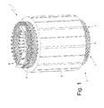
Figure 1 is a schematic perspective view, with parts removed for clarity, of a stator of an electrical machine provided with a stator winding obtained according to the method of construction of the present invention; -
Figure 2 is a perspective and schematic view of a rigid bar bent in a "U" shape forming part of the stator winding of the stator ofFigure 1 ; -
Figure 3 is a perspective, schematic view and with parts removed for clarity, of an initial construction step of the stator winding of the stator ofFigure 1 ; -
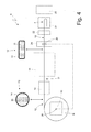
Figure 4 is a schematic view of a construction station of a stator winding with rigid bars which is obtained according to the present invention; -
Figure 5 is a schematic view of a straightening device of the construction station ofFigure 4 ; -
Figure 6 is a schematic view of a roll device of the construction station ofFigure 4 ; and -
Figure 7 is a schematic view of an electrode of a measuring device of the construction station ofFigure 4 . - In
figure 1 , number 1 indicates as a whole a stator of a synchronous electrical machine for auto-traction of reversible type (that is, which may operate both as an electric motor by absorbing electrical power and generating a mechanical driving torque, and as an electric generator absorbing mechanical energy and generating electrical power). The stator 1 has a cylindrical tubular shape and is arranged about a rotor (not illustrated) to enclose the rotor therein. - The stator 1 comprises a
magnetic core 2 which consists of a series of sandwiched sheets and has a tubular shape with a central hole; themagnetic core 2 is longitudinally crossed by thirty-six stator slots which are uniformly distributed along the inner side of themagnetic core 2, and house a three-phase stator winding 3 (obviously the number of stator slots may be different). The three-phase stator winding 3 comprises a series ofrigid U-shaped bars 4, each of which comprises twolegs 5 connected to one another by a cusp 6 (as better illustrated inFigure 2 ); the twolegs 5 of asame bar 4 constitute two corresponding conductors of the stator winding 3. It is worth noting that each U-shapedbar 4 has a "three-dimensional" bending, that is, which provides a bending onto two planes perpendicular one to the other. TheU-shaped bars 4 are inserted through the stator slots defining anentry side 7, in which the cusps 6 of theU-shaped bars 4 are arranged, and anexit side 8, in which thelegs 5 of theU-shaped bars 4 are arranged. In particular, in each slot four legs 5 (that is, four conductors of the stator winding 3) are arranged, belonging to four correspondingrigid U-shaped bars 4 different one from the other. The ends of thelegs 5 of theU-shaped bars 4 are electrically connected to each other to form the electrical paths of the stator winding 3. - Initially, the
rigid bars 4 are centrally bent 180° to be U-shaped and assume the shape shown inFigure 2 . Once the U-shapedbars 4 are ready, theU-shaped bars 4 themselves are inserted into the corresponding stator slots. Said operation can be individually performed (that is, eachU-shaped bar 4 is inserted alone into the corresponding two stator slots), in groups (that is, groups ofU-shaped bars 4 are inserted into the corresponding stator slots), or in one step (that is, all theU-shaped bars 4 are inserted together in the corresponding stator slots with a single insertion movement). When entering all theU-shaped bars 4 into the stator slots is finished, the stator winding 3 is as illustrated inFigure 3 . At this point, thelegs 5 of theU-shaped bars 4 protruding on theexit side 8 of themagnetic core 2 are twisted by means of respective double bends to assume a "Z" shape. Once the twisting of thelegs 5 of theU-shaped bars 4 is completed, the ends of thelegs 5 of theU-shaped bars 4 are electrically connected one to the other (typically by laser performed welding) to form electrical paths of the stator winding 3 also with the aid of suitable connecting bridges consisting of flat plates transversely arranged (i.e. perpendicularly to the central axis of rotation). Further details on the implementation of the stator winding 3 are shown in patent applicationEP2437378A1 . - In
Figure 4 , number 1 indicates as a whole a construction station of thewinding stator 3 withrigid bars 4 illustrated inFigure 1 . - The
construction station 9 comprises anunwinding device 10 for unwinding aninsulated wire 12 of electrically conductor material from acoil 11. The insulatedwire 12 comprises an electrically conductor core 13 (i.e. of metallic material, typically copper) and aninsulating layer 14 surrounding thecore 13 and is typically applied by a coating process. - Furthermore, the
construction station 9 comprises a straighteningdevice 15, which subjects the insulatedwire 12 to a straightening process to eliminate the residual curvature resulting from having been coil-wound. The straighteningdevice 15 is arranged immediately downstream from theunwinding device 10 so that, as soon as it is unwound from thecoil 11, the insulatedwire 12 is, as first processing, subjected to the straightening process. As illustrated inFigure 5 , the straighteningdevice 15 comprises a cascade of straighteningrollers 16 opposite to one another which are idly mounted to freely rotate about respective axes 17 of rotation and defining one with the other a rectilinear path that the insulatedwire 12 is "forced" to follow. According to a preferred embodiment illustrated inFigure 5 , each straighteningroller 16 has anannular groove 18 which reproduces in negative the shape of the insulatedwire 12 and houses the insulatedwire 12 therein to better guide the feeding of the insulatedwire 12. In the embodiment illustrated inFigure 5 , thestraightening device 15 comprises only one cascade of straighteningrollers 16 opposite one to the other having the axes 17 of rotation arranged horizontally; according to a different and perfectly equivalent embodiment, thestraightening device 15 comprises a first cascade of straighteningrollers 16 opposite one to the other having the axes 17 of rotation arranged horizontally (as illustrated inFigure 5 ) and a second cascade of straighteningrollers 16 opposite one to the other having the axes 17 of rotation arranged vertically (i.e. perpendicularly to the first cascade of straighteningrollers 16 opposite one to the other). - As illustrated in
Figure 4 , theconstruction station 9 comprises aroll device 18 which subjects theinsulated wire 12, initially having a circular cross section, to a cold-roll process to give the wire 12 a rectangular cross section. In other words, the insulatedwire 12 wound into acoil 11 has a circular cross-section (as illustrated on the left inFigure 4 ) which is converted into a rectangular cross section (as illustrated on the right inFigure 4 ) by the cold-roll process imparted by theroll device 18. It is important to note that the insulatedwire 12 is subjected to the cold-roll process when already provided with the insulatinglayer 14; therefore the cold-roll process to which the insulatedwire 12 is subjected deforms at the same time both themetallic core 13 of the insulatedwire 12, and theinsulating layer 14 of the insulatedwire 12 surrounding thecore 13. - As illustrated in
Figure 6 , theroll device 18 comprises four pairs ofrolling cylinders 19 opposite one to the other which rotate aboutrespective axes 20 of rotation. Preferably, the four pairs ofrolling cylinders 19 are motorized (i.e. are brought into rotation by respective electric motors or by a single electric motor common to all the pairs of rolling cylinders 19). In the embodiment illustrated inFigure 6 , theroll device 18 comprises four pairs ofrolling cylinders 19 opposite one to the other: a first pair ofrolling cylinders 19 opposite one to the other is oriented horizontally, a second pair ofrolling cylinders 19 opposite one to the other is oriented vertically (i.e. perpendicular to the first pair ofrolling cylinders 19 opposite one to the other), a third pair ofrolling cylinders 19 opposite one to the other is oriented horizontally (as the first pair ofrolling cylinders 19 opposite one to the other), and a fourth pair ofrolling cylinders 19 opposite one to the other is oriented vertically (as the second pair ofrolling cylinders 19 opposite one to the other and perpendicularly to the third pair ofrolling cylinders 19 opposite one to the other). According to an alternative embodiment perfectly equivalent and not illustrated, theroll device 18 comprises a different number of pairs ofrolling cylinders 19 opposite one to the other: for example, two, three, five or six pairs ofrolling cylinders 19 opposite one to the other. - As clearly illustrated in
Figure 4 , the insulatedwire 12 is subjected to the straightening process in the straighteningdevice 15 immediately before being subjected to the cold-roll process in theroll device 18. - As illustrated in
Figure 4 , theconstruction station 9 comprises a bending device 21 (known and not illustrated in detail) that bends in a "U" shape a final end of the insulatedwire 12 so as to obtain abar 4 having twolegs 5 connected to one another by a cusp 6 (as better illustrated inFigure 2 ) and a cutting device 22 (known and not illustrated in detail) which transversely cuts theinsulated wire 12 to separate therigid bar 4 from the remaining part of thewire 12. It is important to underline that the bending in a "U" shape of the final end of the insulatedwire 12 to obtain thebar 4 can be indifferently performed before or after the transverse cutting of the insulatedwire 12 to separate therigid bar 4 from the remaining part of the insulatedwire 12. In other words, it is possible to transversely cut thewire 12 to separate thebar 4, still straight, and then bend in a "U" shape thebar 4 only after the cut, or it is possible to transversely cut thewire 12 after the "U" shape bending to separate thebar 4 already bent in a "U" shape. - As illustrated in
Figure 4 , theconstruction station 9 comprises an inserting device 23 (known and not illustrated in detail), which withdraws one by one thebars 4 bent in a "U" shape from thebending device 21 and inserts (individually, in groups or all together) thebars 4 bent in a "U" shape in the corresponding stator slots of thecore 2 of the stator 1 (as previously described and as illustrated inFigure 3 ). Theconstruction station 9 comprises additional operating devices (known and not illustrated) that perform the other operations described above to complete the construction of the stator winding 3. - As illustrated in
Figure 4 , the insulatedwire 12 is subjected to the cold-roll process in theroll device 18 before being bent and/or transversely cut in thebending device 21 and in thecutting device 22, respectively. - According to a preferred embodiment illustrated in
Figure 4 , theconstruction station 9 comprises a measuringdevice 24 measuring in-line the electrical conductivity between the core 13 and the outer surface of theinsulated wire 12 by anelectrode 25 electrically and permanently connected to thecore 13 of the insulated wire 12 (at the unwinding device 10) and anelectrode 26, which rubs against the outer surface of the insulated wire 12 (as better illustrated inFigure 7 ), i.e. rubs against the insulatinglayer 14 of theinsulated wire 12. In other words, the measuringdevice 24 detects the continuity of the insulatinglayer 14 of theinsulated wire 12 to verify that the insulatinglayer 14 is intact; said detection is performed by measuring the electrical conductivity between the core 13 and the outer surface of theinsulated wire 12, i.e. by verifying if there is a sufficient electrical insulation between the core 13 and the outer surface of theinsulated wire 12. - The
electrode 25 normally comprises a conductor clamp (of known type) which is fixed to a leading end of theinsulated wire 12 which is integral with thecoil 11 and is "stripped" (i.e. cleaned of the insulating layer 14) so as to uncover theunderlying conductor core 13. Theelectrode 26 is arranged in a fixed position along the feeding path of theinsulated wire 12 so that the feeding of theinsulated wire 12 causes theelectrode 26 to rub against the outer surface of the insulated wire 12 (i.e. against the insulating layer 14). As illustrated inFigure 7 , theelectrode 26 comprises anannular brush 27 inside which theinsulated wire 12 slides and provided with a plurality of flexible and electrically conductor bristles 28 facing inwards. Thebristles 28 are made of a "tender" flexible conductor material so as to not damage the insulatinglayer 14 following the sliding action; for example, thebristles 28 may be flexible, made of brass or carbon or the like. - When the measuring
device 24 finds that a part of theinsulated wire 12 does not have the necessary degree of insulation, then a discharge process is activated which leads to discarding a portion of the insulated wire from theproductive process 12 at whose center the part not having the required degree of insulation can be found. In other words a portion of theinsulated wire 12 is discarded at whose center a part having an electrical conductivity greater than a predetermined threshold value can be found (i.e. without the necessary degree of insulation). - According to a preferred embodiment illustrated in
Figure 4 , the measuringdevice 24 is arranged downstream from theroll device 18 for measuring the electrical conductivity after having subjected the insulatedwire 12 to the cold-roll process. The function of the measuringdevice 24 is both to identify any defects in the insulatinglayer 14 present from the beginning, and to identify any defects in the insulatinglayer 14 caused by the straightening process operated by the straighteningdevice 15 and/or by the cold-roll process operated by theroll device 18. - In the embodiment illustrated in the attached figures, the cold-roll process gives the insulated wire 12 a rectangular cross section (a possible square cross section is a particular case of the rectangular cross section); according to a different embodiment, the cold-roll process gives the insulated wire 12 a polygonal cross-section different from the rectangular section, for example a trapezoidal cross-section.
- The method of construction described above has numerous advantages.
- In the first place, it was observed that starting from an
insulated wire 12 having a circular cross section which is cold-rolled to obtain aninsulated wire 12 having a rectangular section it is possible to obtain aninsulated wire 12 having a rectangular section which has a very uniform insulating layer 14 (that is, having constant thickness over the entire surface and particularly at the edges) and very well adherent to the underlying core 13 (i.e. little inclined to detaching even when subjected to bending). Therefore, starting from aninsulated wire 12 having a circular cross section which is cold-rolled to obtain aninsulated wire 12 having a rectangular section it is possible to use a particularly small thickness of the insulating layer 14 (i.e. minimum thickness to withstand the maximum voltage difference that in use is found inside the stator winding 3), that is, it is not necessary to use any oversizing of the thickness of the insulatinglayer 14 to compensate for unevenness and irregularity of the insulatinglayer 14. In addition, by reducing the frequency of detachment of the insulatinglayer 14 it is possible to significantly reduce the number ofrigid bars 4 discarded thereby reducing the production cost of the stator winding 3. - In addition, on the market insulated
wires 12 having a circular cross-section of any measure are readily available from many different suppliers; however, on the market insulatedwires 12 having a rectangular cross-section are much more difficult to obtain. Therefore, the fact of usinginsulated wires 12 having a circular cross section instead ofinsulated wire 12 having a rectangular cross section makes it much simpler (and therefore inexpensive, being able to choose from many different suppliers) the purchase of thecoils 11 of insulatedwire 12. - Thanks to the presence of the measuring
device 24 it is possible to verify in a simple, fast and reliable way the quality of the insulatinglayer 14; then it is possible to increase the reliability of the stator winding 3, as the possibility that over time in the stator winding 3 short-circuits between therigid bars 4 during operation of the electrical machine occur is significantly reduced. - Finally, the method of construction described above has numerous advantages, is simple and inexpensive to produce, since the
roll device 18 is inexpensive and very reliable, having a low cost and being particularly compact.
Claims (6)
- A method for the construction of a stator winding (3) with rigid bars (4) for a rotary electrical machine; the method of construction comprises the steps of:unwinding, from a coil (11), an insulated wire (12) comprising an electrically conductor core (13) and an insulating layer (14) arranged on the outside and surrounding the core (13);bending, in sequence, the final end of the insulated wire (12) in a "U" shape, so as to create a plurality of bars (4), each having two legs (5) connected to one another by a cusp (6);transversely cutting the insulated wire (12) in sequence, so as to separate the rigid bars (4) from the remaining part of the wire (12); andinserting the rigid bars (4) into corresponding stator slots of a magnetic core (2) of a stator (1);the method of construction is characterized in that it comprises the further step of measuring the electrical conductivity between the core (13) and the outer surface of the insulated wire (12) by means of a first electrode (25), which is electrically and permanently connected to the core (13) of the insulated wire (12), and by means of a second electrode (26), which rubs against the outer surface of the insulated wire (12).
- A method of construction according to claim 1, wherein the second electrode (26) is arranged in a fixed position along the feeding path (12) of the insulated wire (12), so that the feeding of the insulated wire (12) causes the second electrode (26) to rub against the outer surface of the insulated wire (12).
- A method of construction according to claim 1 or 2, wherein the second electrode (26) comprises an annular brush (27), inside which the insulated wire (12) slides and which is provided with a plurality of flexible and electrically conductor bristles (28) facing inwards.
- A method of construction according to claim 1, 2 or 3 and comprising the further step of discarding a segment of the insulated wire (12) that has, at the centre, a part having an electrical conductivity that is greater than a predetermined threshold value.
- A method of construction according to any of the claims from 1 to 4, wherein the electrical conductivity is measured before bending in a "U" shape the final end of the insulated wire (12).
- A station (9) for the construction of a stator winding (3) with rigid bars (4) for a rotary electrical machine; the construction station (9) comprises:an unwinding device (10), which unwinds, from a coil (11), an insulated wire (12) comprising an electrically conductor core (13) and an insulating layer (14) arranged on the outside and surrounding the core (13);a bending device (21), which bends, in sequence, the final end of the insulated wire (12) in a "U" shape, so as to create a plurality of bars (4), each having two legs (5) connected to one another by a cusp (6);a cutting device (22), which transversely cuts the insulated wire (12) in sequence, so as to separate the rigid bars (4) from the remaining part of the wire (12); andan inserting device (23), which inserts the rigid bars (4) into corresponding stator slots of a magnetic core (2) of a stator (1);the construction station (9) is characterized in that it comprises a measuring device (23), which measures the electrical conductivity between the core (13) and the outer surface of the insulated wire (12) by means of a first electrode (25), which is electrically and permanently connected to the core (13) of the insulated wire (12), and by means of a second electrode (26), which rubs against the outer surface of the insulated wire (12).
Applications Claiming Priority (1)
| Application Number | Priority Date | Filing Date | Title |
|---|---|---|---|
| ITBO20140643 | 2014-11-14 |
Publications (2)
| Publication Number | Publication Date |
|---|---|
| EP3021467A1 true EP3021467A1 (en) | 2016-05-18 |
| EP3021467B1 EP3021467B1 (en) | 2017-08-16 |
Family
ID=52350197
Family Applications (1)
| Application Number | Title | Priority Date | Filing Date |
|---|---|---|---|
| EP15194634.0A Active EP3021467B1 (en) | 2014-11-14 | 2015-11-13 | Method and station for the construction of a stator winding with rigid bars for a rotary electrical machine |
Country Status (3)
| Country | Link |
|---|---|
| US (1) | US9973064B2 (en) |
| EP (1) | EP3021467B1 (en) |
| CN (1) | CN105610283B (en) |
Cited By (2)
| Publication number | Priority date | Publication date | Assignee | Title |
|---|---|---|---|---|
| WO2019036736A1 (en) * | 2017-08-23 | 2019-02-28 | Miba Aktiengesellschaft | MANUFACTURING SYSTEM FOR MANUFACTURING A WINDING BAR FOR AN ELECTRIC MOTOR, AND METHOD FOR PRODUCING THE WINDING BAR |
| EP3910767A1 (en) * | 2020-05-13 | 2021-11-17 | Gehring Technologies GmbH + Co. KG | Device and method for stripping insulation from conductor pieces |
Families Citing this family (4)
| Publication number | Priority date | Publication date | Assignee | Title |
|---|---|---|---|---|
| US10132854B2 (en) * | 2016-09-27 | 2018-11-20 | Faraday & Future Inc. | Systems and methods for evaluating insulation of formed wire or wires |
| DE102020201049A1 (en) | 2020-01-29 | 2021-07-29 | Thyssenkrupp Ag | Isolation Test Method and Apparatus |
| IT202100027599A1 (en) * | 2021-10-28 | 2023-04-28 | Marposs Spa | METHOD AND CONTROL UNIT OF A HAIRBORN-BENT RIGID BAR FOR THE CONSTRUCTION OF A STATOR WINDING OF A ROTARY ELECTRIC MACHINE |
| EP4686954A1 (en) * | 2024-08-01 | 2026-02-04 | Grob-Werke GmbH & Co. KG | Testing an insulation of a conductor segment for an electric machine, provision of conductor segments with a test, and test device for carrying out the test |
Citations (3)
| Publication number | Priority date | Publication date | Assignee | Title |
|---|---|---|---|---|
| US7480987B1 (en) | 2007-03-22 | 2009-01-27 | Tecnomatic, S.P.A. | Method for pre-forming conductors for motor rotors and stators |
| EP2287625A1 (en) * | 2009-08-13 | 2011-02-23 | Alstom Technology Ltd | Device and method for detecting defects within the insulation of an insulated conductor |
| EP2437378A1 (en) | 2010-09-29 | 2012-04-04 | Magneti Marelli S.p.A. | Eelectric machine having a stator winding with rigid bars, and related method of construction |
Family Cites Families (4)
| Publication number | Priority date | Publication date | Assignee | Title |
|---|---|---|---|---|
| FR2808939B1 (en) * | 2000-05-11 | 2002-07-12 | Valeo Equip Electr Moteur | MACHINE FOR SHAPING THE HEAD OF A STATOR |
| JP3738733B2 (en) * | 2002-01-18 | 2006-01-25 | 株式会社デンソー | Stator for rotating electrical machine for vehicle and method for manufacturing the same |
| US7659728B1 (en) * | 2006-08-23 | 2010-02-09 | Watkins Jr Kenneth S | Method and apparatus for measuring degradation of insulation of electrical power system devices |
| JP5749772B2 (en) * | 2013-09-18 | 2015-07-15 | 本田技研工業株式会社 | Insertion method and insertion device |
-
2015
- 2015-11-13 US US14/940,294 patent/US9973064B2/en active Active
- 2015-11-13 EP EP15194634.0A patent/EP3021467B1/en active Active
- 2015-11-16 CN CN201510784816.2A patent/CN105610283B/en active Active
Patent Citations (3)
| Publication number | Priority date | Publication date | Assignee | Title |
|---|---|---|---|---|
| US7480987B1 (en) | 2007-03-22 | 2009-01-27 | Tecnomatic, S.P.A. | Method for pre-forming conductors for motor rotors and stators |
| EP2287625A1 (en) * | 2009-08-13 | 2011-02-23 | Alstom Technology Ltd | Device and method for detecting defects within the insulation of an insulated conductor |
| EP2437378A1 (en) | 2010-09-29 | 2012-04-04 | Magneti Marelli S.p.A. | Eelectric machine having a stator winding with rigid bars, and related method of construction |
Cited By (5)
| Publication number | Priority date | Publication date | Assignee | Title |
|---|---|---|---|---|
| WO2019036736A1 (en) * | 2017-08-23 | 2019-02-28 | Miba Aktiengesellschaft | MANUFACTURING SYSTEM FOR MANUFACTURING A WINDING BAR FOR AN ELECTRIC MOTOR, AND METHOD FOR PRODUCING THE WINDING BAR |
| AT520364A1 (en) * | 2017-08-23 | 2019-03-15 | Miba Ag | Production plant for producing a winding rod for an electric motor, and method for producing the winding rod |
| AT520364B1 (en) * | 2017-08-23 | 2019-11-15 | Miba Ag | Production plant for producing a winding rod for an electric motor, and method for producing the winding rod |
| CN111357177A (en) * | 2017-08-23 | 2020-06-30 | 米巴自动化系统有限公司 | Manufacturing apparatus for manufacturing winding bars for electric motors and method for manufacturing winding bars |
| EP3910767A1 (en) * | 2020-05-13 | 2021-11-17 | Gehring Technologies GmbH + Co. KG | Device and method for stripping insulation from conductor pieces |
Also Published As
| Publication number | Publication date |
|---|---|
| EP3021467B1 (en) | 2017-08-16 |
| CN105610283A (en) | 2016-05-25 |
| CN105610283B (en) | 2019-09-13 |
| US9973064B2 (en) | 2018-05-15 |
| US20160141943A1 (en) | 2016-05-19 |
Similar Documents
| Publication | Publication Date | Title |
|---|---|---|
| EP3021467B1 (en) | Method and station for the construction of a stator winding with rigid bars for a rotary electrical machine | |
| US9634548B2 (en) | Method for manufacturing an armature winding for an electric machine | |
| US20090265909A1 (en) | Method and apparatus for removing winding conductors from a twisting machine and placing them in a rotor or stator stack | |
| EP1225679B1 (en) | Method and apparatus for winding field coils of two-pole stators | |
| KR101950528B1 (en) | Continuously trasnposed conductor | |
| US20180088168A1 (en) | Systems and methods for evaluating insulation of formed wire or wires | |
| US9705374B2 (en) | Rotary electric machine and a manufacturing method thereof | |
| KR101319500B1 (en) | Methed for manufacturing of stator and electric motor having thereof, electric vechile having electric motor | |
| US11837933B2 (en) | Process for making an electric conductor for a winding of an electric machine, electric conductor made with such process and electric machine comprising a winding made with such electric conductor | |
| KR20130028566A (en) | Stator and methed for manufacturing of stator and electric motor having thereof, electric vechile having electric motor | |
| CN113853733B (en) | Method for producing a stator for an electric machine | |
| US8701269B2 (en) | Methods for forming female connectors integral with the stator winding conductors | |
| CN107659072B (en) | Repair method of motor stator of aircraft power transmission device | |
| JP2015167098A (en) | Aggregated conductor wire, manufacturing method thereof, and stator | |
| CN114391210B (en) | Strip-shaped winding unit for stator winding and method for producing the strip-shaped winding unit | |
| US10523076B2 (en) | Method of making multi-turn coils | |
| JP5944713B2 (en) | Stator manufacturing method | |
| US20210184549A1 (en) | Method of making electric machine windings with segmented conductors | |
| CN103516150B (en) | For manufacturing the method for the coil of motor | |
| EP4451522A1 (en) | Stator coil insulation | |
| RU2821307C1 (en) | Installation and method of making litz wire for windings for synchronous electric machines | |
| CN105226890B (en) | Wire arranging method for motor stator winding | |
| JP2010283940A (en) | Rotating electric machine | |
| RU2529012C2 (en) | Method of manufacture of single-turn rigid form-wound loop coil of two-layer winding stator | |
| DE102023004775A1 (en) | Method for producing a winding wire for an electrical machine for an at least partially electrically operated motor vehicle by means of a production device |
Legal Events
| Date | Code | Title | Description |
|---|---|---|---|
| PUAI | Public reference made under article 153(3) epc to a published international application that has entered the european phase |
Free format text: ORIGINAL CODE: 0009012 |
|
| AK | Designated contracting states |
Kind code of ref document: A1 Designated state(s): AL AT BE BG CH CY CZ DE DK EE ES FI FR GB GR HR HU IE IS IT LI LT LU LV MC MK MT NL NO PL PT RO RS SE SI SK SM TR |
|
| AX | Request for extension of the european patent |
Extension state: BA ME |
|
| 17P | Request for examination filed |
Effective date: 20161118 |
|
| GRAP | Despatch of communication of intention to grant a patent |
Free format text: ORIGINAL CODE: EPIDOSNIGR1 |
|
| INTG | Intention to grant announced |
Effective date: 20170307 |
|
| GRAS | Grant fee paid |
Free format text: ORIGINAL CODE: EPIDOSNIGR3 |
|
| GRAA | (expected) grant |
Free format text: ORIGINAL CODE: 0009210 |
|
| AK | Designated contracting states |
Kind code of ref document: B1 Designated state(s): AL AT BE BG CH CY CZ DE DK EE ES FI FR GB GR HR HU IE IS IT LI LT LU LV MC MK MT NL NO PL PT RO RS SE SI SK SM TR |
|
| REG | Reference to a national code |
Ref country code: GB Ref legal event code: FG4D |
|
| REG | Reference to a national code |
Ref country code: CH Ref legal event code: EP |
|
| REG | Reference to a national code |
Ref country code: IE Ref legal event code: FG4D |
|
| REG | Reference to a national code |
Ref country code: AT Ref legal event code: REF Ref document number: 919975 Country of ref document: AT Kind code of ref document: T Effective date: 20170915 |
|
| REG | Reference to a national code |
Ref country code: DE Ref legal event code: R096 Ref document number: 602015004146 Country of ref document: DE |
|
| REG | Reference to a national code |
Ref country code: FR Ref legal event code: PLFP Year of fee payment: 3 |
|
| REG | Reference to a national code |
Ref country code: NL Ref legal event code: MP Effective date: 20170816 |
|
| REG | Reference to a national code |
Ref country code: LT Ref legal event code: MG4D |
|
| REG | Reference to a national code |
Ref country code: AT Ref legal event code: MK05 Ref document number: 919975 Country of ref document: AT Kind code of ref document: T Effective date: 20170816 |
|
| PG25 | Lapsed in a contracting state [announced via postgrant information from national office to epo] |
Ref country code: LT Free format text: LAPSE BECAUSE OF FAILURE TO SUBMIT A TRANSLATION OF THE DESCRIPTION OR TO PAY THE FEE WITHIN THE PRESCRIBED TIME-LIMIT Effective date: 20170816 Ref country code: NL Free format text: LAPSE BECAUSE OF FAILURE TO SUBMIT A TRANSLATION OF THE DESCRIPTION OR TO PAY THE FEE WITHIN THE PRESCRIBED TIME-LIMIT Effective date: 20170816 Ref country code: AT Free format text: LAPSE BECAUSE OF FAILURE TO SUBMIT A TRANSLATION OF THE DESCRIPTION OR TO PAY THE FEE WITHIN THE PRESCRIBED TIME-LIMIT Effective date: 20170816 Ref country code: SE Free format text: LAPSE BECAUSE OF FAILURE TO SUBMIT A TRANSLATION OF THE DESCRIPTION OR TO PAY THE FEE WITHIN THE PRESCRIBED TIME-LIMIT Effective date: 20170816 Ref country code: FI Free format text: LAPSE BECAUSE OF FAILURE TO SUBMIT A TRANSLATION OF THE DESCRIPTION OR TO PAY THE FEE WITHIN THE PRESCRIBED TIME-LIMIT Effective date: 20170816 Ref country code: NO Free format text: LAPSE BECAUSE OF FAILURE TO SUBMIT A TRANSLATION OF THE DESCRIPTION OR TO PAY THE FEE WITHIN THE PRESCRIBED TIME-LIMIT Effective date: 20171116 |
|
| PG25 | Lapsed in a contracting state [announced via postgrant information from national office to epo] |
Ref country code: RS Free format text: LAPSE BECAUSE OF FAILURE TO SUBMIT A TRANSLATION OF THE DESCRIPTION OR TO PAY THE FEE WITHIN THE PRESCRIBED TIME-LIMIT Effective date: 20170816 Ref country code: BG Free format text: LAPSE BECAUSE OF FAILURE TO SUBMIT A TRANSLATION OF THE DESCRIPTION OR TO PAY THE FEE WITHIN THE PRESCRIBED TIME-LIMIT Effective date: 20171116 Ref country code: ES Free format text: LAPSE BECAUSE OF FAILURE TO SUBMIT A TRANSLATION OF THE DESCRIPTION OR TO PAY THE FEE WITHIN THE PRESCRIBED TIME-LIMIT Effective date: 20170816 Ref country code: PL Free format text: LAPSE BECAUSE OF FAILURE TO SUBMIT A TRANSLATION OF THE DESCRIPTION OR TO PAY THE FEE WITHIN THE PRESCRIBED TIME-LIMIT Effective date: 20170816 Ref country code: GR Free format text: LAPSE BECAUSE OF FAILURE TO SUBMIT A TRANSLATION OF THE DESCRIPTION OR TO PAY THE FEE WITHIN THE PRESCRIBED TIME-LIMIT Effective date: 20171117 Ref country code: IS Free format text: LAPSE BECAUSE OF FAILURE TO SUBMIT A TRANSLATION OF THE DESCRIPTION OR TO PAY THE FEE WITHIN THE PRESCRIBED TIME-LIMIT Effective date: 20171216 Ref country code: LV Free format text: LAPSE BECAUSE OF FAILURE TO SUBMIT A TRANSLATION OF THE DESCRIPTION OR TO PAY THE FEE WITHIN THE PRESCRIBED TIME-LIMIT Effective date: 20170816 |
|
| PG25 | Lapsed in a contracting state [announced via postgrant information from national office to epo] |
Ref country code: RO Free format text: LAPSE BECAUSE OF FAILURE TO SUBMIT A TRANSLATION OF THE DESCRIPTION OR TO PAY THE FEE WITHIN THE PRESCRIBED TIME-LIMIT Effective date: 20170816 Ref country code: CZ Free format text: LAPSE BECAUSE OF FAILURE TO SUBMIT A TRANSLATION OF THE DESCRIPTION OR TO PAY THE FEE WITHIN THE PRESCRIBED TIME-LIMIT Effective date: 20170816 Ref country code: DK Free format text: LAPSE BECAUSE OF FAILURE TO SUBMIT A TRANSLATION OF THE DESCRIPTION OR TO PAY THE FEE WITHIN THE PRESCRIBED TIME-LIMIT Effective date: 20170816 |
|
| REG | Reference to a national code |
Ref country code: DE Ref legal event code: R097 Ref document number: 602015004146 Country of ref document: DE |
|
| PG25 | Lapsed in a contracting state [announced via postgrant information from national office to epo] |
Ref country code: SM Free format text: LAPSE BECAUSE OF FAILURE TO SUBMIT A TRANSLATION OF THE DESCRIPTION OR TO PAY THE FEE WITHIN THE PRESCRIBED TIME-LIMIT Effective date: 20170816 Ref country code: SK Free format text: LAPSE BECAUSE OF FAILURE TO SUBMIT A TRANSLATION OF THE DESCRIPTION OR TO PAY THE FEE WITHIN THE PRESCRIBED TIME-LIMIT Effective date: 20170816 Ref country code: EE Free format text: LAPSE BECAUSE OF FAILURE TO SUBMIT A TRANSLATION OF THE DESCRIPTION OR TO PAY THE FEE WITHIN THE PRESCRIBED TIME-LIMIT Effective date: 20170816 |
|
| PLBE | No opposition filed within time limit |
Free format text: ORIGINAL CODE: 0009261 |
|
| STAA | Information on the status of an ep patent application or granted ep patent |
Free format text: STATUS: NO OPPOSITION FILED WITHIN TIME LIMIT |
|
| PG25 | Lapsed in a contracting state [announced via postgrant information from national office to epo] |
Ref country code: MC Free format text: LAPSE BECAUSE OF FAILURE TO SUBMIT A TRANSLATION OF THE DESCRIPTION OR TO PAY THE FEE WITHIN THE PRESCRIBED TIME-LIMIT Effective date: 20170816 |
|
| 26N | No opposition filed |
Effective date: 20180517 |
|
| PG25 | Lapsed in a contracting state [announced via postgrant information from national office to epo] |
Ref country code: LU Free format text: LAPSE BECAUSE OF NON-PAYMENT OF DUE FEES Effective date: 20171113 Ref country code: SI Free format text: LAPSE BECAUSE OF FAILURE TO SUBMIT A TRANSLATION OF THE DESCRIPTION OR TO PAY THE FEE WITHIN THE PRESCRIBED TIME-LIMIT Effective date: 20170816 |
|
| REG | Reference to a national code |
Ref country code: BE Ref legal event code: MM Effective date: 20171130 |
|
| REG | Reference to a national code |
Ref country code: IE Ref legal event code: MM4A |
|
| PG25 | Lapsed in a contracting state [announced via postgrant information from national office to epo] |
Ref country code: MT Free format text: LAPSE BECAUSE OF NON-PAYMENT OF DUE FEES Effective date: 20171113 |
|
| REG | Reference to a national code |
Ref country code: FR Ref legal event code: PLFP Year of fee payment: 4 |
|
| PG25 | Lapsed in a contracting state [announced via postgrant information from national office to epo] |
Ref country code: IE Free format text: LAPSE BECAUSE OF NON-PAYMENT OF DUE FEES Effective date: 20171113 |
|
| PG25 | Lapsed in a contracting state [announced via postgrant information from national office to epo] |
Ref country code: BE Free format text: LAPSE BECAUSE OF NON-PAYMENT OF DUE FEES Effective date: 20171130 |
|
| PG25 | Lapsed in a contracting state [announced via postgrant information from national office to epo] |
Ref country code: HU Free format text: LAPSE BECAUSE OF FAILURE TO SUBMIT A TRANSLATION OF THE DESCRIPTION OR TO PAY THE FEE WITHIN THE PRESCRIBED TIME-LIMIT; INVALID AB INITIO Effective date: 20151113 |
|
| REG | Reference to a national code |
Ref country code: CH Ref legal event code: PL |
|
| PG25 | Lapsed in a contracting state [announced via postgrant information from national office to epo] |
Ref country code: CH Free format text: LAPSE BECAUSE OF NON-PAYMENT OF DUE FEES Effective date: 20181130 Ref country code: LI Free format text: LAPSE BECAUSE OF NON-PAYMENT OF DUE FEES Effective date: 20181130 |
|
| PG25 | Lapsed in a contracting state [announced via postgrant information from national office to epo] |
Ref country code: CY Free format text: LAPSE BECAUSE OF FAILURE TO SUBMIT A TRANSLATION OF THE DESCRIPTION OR TO PAY THE FEE WITHIN THE PRESCRIBED TIME-LIMIT Effective date: 20170816 |
|
| PG25 | Lapsed in a contracting state [announced via postgrant information from national office to epo] |
Ref country code: MK Free format text: LAPSE BECAUSE OF FAILURE TO SUBMIT A TRANSLATION OF THE DESCRIPTION OR TO PAY THE FEE WITHIN THE PRESCRIBED TIME-LIMIT Effective date: 20170816 |
|
| PG25 | Lapsed in a contracting state [announced via postgrant information from national office to epo] |
Ref country code: PT Free format text: LAPSE BECAUSE OF FAILURE TO SUBMIT A TRANSLATION OF THE DESCRIPTION OR TO PAY THE FEE WITHIN THE PRESCRIBED TIME-LIMIT Effective date: 20170816 |
|
| PG25 | Lapsed in a contracting state [announced via postgrant information from national office to epo] |
Ref country code: HR Free format text: LAPSE BECAUSE OF FAILURE TO SUBMIT A TRANSLATION OF THE DESCRIPTION OR TO PAY THE FEE WITHIN THE PRESCRIBED TIME-LIMIT Effective date: 20170816 |
|
| PG25 | Lapsed in a contracting state [announced via postgrant information from national office to epo] |
Ref country code: AL Free format text: LAPSE BECAUSE OF FAILURE TO SUBMIT A TRANSLATION OF THE DESCRIPTION OR TO PAY THE FEE WITHIN THE PRESCRIBED TIME-LIMIT Effective date: 20170816 |
|
| GBPC | Gb: european patent ceased through non-payment of renewal fee |
Effective date: 20191113 |
|
| PG25 | Lapsed in a contracting state [announced via postgrant information from national office to epo] |
Ref country code: GB Free format text: LAPSE BECAUSE OF NON-PAYMENT OF DUE FEES Effective date: 20191113 |
|
| PGFP | Annual fee paid to national office [announced via postgrant information from national office to epo] |
Ref country code: DE Payment date: 20251022 Year of fee payment: 11 |
|
| PGFP | Annual fee paid to national office [announced via postgrant information from national office to epo] |
Ref country code: IT Payment date: 20251022 Year of fee payment: 11 |
|
| PGFP | Annual fee paid to national office [announced via postgrant information from national office to epo] |
Ref country code: FR Payment date: 20251022 Year of fee payment: 11 |
|
| PGFP | Annual fee paid to national office [announced via postgrant information from national office to epo] |
Ref country code: TR Payment date: 20251027 Year of fee payment: 11 |