EP3021399A1 - Fuel cell system and method of controlling fuel cell - Google Patents
Fuel cell system and method of controlling fuel cell Download PDFInfo
- Publication number
- EP3021399A1 EP3021399A1 EP15190004.0A EP15190004A EP3021399A1 EP 3021399 A1 EP3021399 A1 EP 3021399A1 EP 15190004 A EP15190004 A EP 15190004A EP 3021399 A1 EP3021399 A1 EP 3021399A1
- Authority
- EP
- European Patent Office
- Prior art keywords
- control
- upper limit
- value
- current value
- fuel cell
- Prior art date
- Legal status (The legal status is an assumption and is not a legal conclusion. Google has not performed a legal analysis and makes no representation as to the accuracy of the status listed.)
- Granted
Links
- 238000000034 method Methods 0.000 title claims abstract description 14
- 239000000446 fuel Substances 0.000 title claims description 80
- 238000010248 power generation Methods 0.000 claims description 46
- 239000007789 gas Substances 0.000 description 51
- 238000012545 processing Methods 0.000 description 23
- 239000002826 coolant Substances 0.000 description 17
- 239000001257 hydrogen Substances 0.000 description 17
- 229910052739 hydrogen Inorganic materials 0.000 description 17
- UFHFLCQGNIYNRP-UHFFFAOYSA-N Hydrogen Chemical compound [H][H] UFHFLCQGNIYNRP-UHFFFAOYSA-N 0.000 description 16
- 238000012937 correction Methods 0.000 description 12
- 239000007788 liquid Substances 0.000 description 7
- 238000000926 separation method Methods 0.000 description 7
- 239000012528 membrane Substances 0.000 description 5
- 238000010586 diagram Methods 0.000 description 4
- 238000006243 chemical reaction Methods 0.000 description 3
- 239000003792 electrolyte Substances 0.000 description 3
- 238000011144 upstream manufacturing Methods 0.000 description 3
- IJGRMHOSHXDMSA-UHFFFAOYSA-N Atomic nitrogen Chemical compound N#N IJGRMHOSHXDMSA-UHFFFAOYSA-N 0.000 description 2
- 238000004590 computer program Methods 0.000 description 2
- 238000001816 cooling Methods 0.000 description 2
- 238000007599 discharging Methods 0.000 description 2
- BASFCYQUMIYNBI-UHFFFAOYSA-N platinum Chemical compound [Pt] BASFCYQUMIYNBI-UHFFFAOYSA-N 0.000 description 2
- 239000012495 reaction gas Substances 0.000 description 2
- 239000007787 solid Substances 0.000 description 2
- OKTJSMMVPCPJKN-UHFFFAOYSA-N Carbon Chemical compound [C] OKTJSMMVPCPJKN-UHFFFAOYSA-N 0.000 description 1
- HBBGRARXTFLTSG-UHFFFAOYSA-N Lithium ion Chemical compound [Li+] HBBGRARXTFLTSG-UHFFFAOYSA-N 0.000 description 1
- 229910052799 carbon Inorganic materials 0.000 description 1
- 230000015556 catabolic process Effects 0.000 description 1
- 239000003054 catalyst Substances 0.000 description 1
- 238000004891 communication Methods 0.000 description 1
- 239000000470 constituent Substances 0.000 description 1
- 239000000498 cooling water Substances 0.000 description 1
- 230000003247 decreasing effect Effects 0.000 description 1
- 238000006731 degradation reaction Methods 0.000 description 1
- 230000000593 degrading effect Effects 0.000 description 1
- 230000000694 effects Effects 0.000 description 1
- 238000005516 engineering process Methods 0.000 description 1
- 150000002431 hydrogen Chemical class 0.000 description 1
- 239000011261 inert gas Substances 0.000 description 1
- 229910001416 lithium ion Inorganic materials 0.000 description 1
- 238000005259 measurement Methods 0.000 description 1
- 229910052757 nitrogen Inorganic materials 0.000 description 1
- 229910052697 platinum Inorganic materials 0.000 description 1
- 229920000642 polymer Polymers 0.000 description 1
- 230000001172 regenerating effect Effects 0.000 description 1
- 239000010409 thin film Substances 0.000 description 1
Images


Classifications
-
- G—PHYSICS
- G05—CONTROLLING; REGULATING
- G05B—CONTROL OR REGULATING SYSTEMS IN GENERAL; FUNCTIONAL ELEMENTS OF SUCH SYSTEMS; MONITORING OR TESTING ARRANGEMENTS FOR SUCH SYSTEMS OR ELEMENTS
- G05B19/00—Programme-control systems
- G05B19/02—Programme-control systems electric
- G05B19/04—Programme control other than numerical control, i.e. in sequence controllers or logic controllers
- G05B19/048—Monitoring; Safety
-
- H—ELECTRICITY
- H01—ELECTRIC ELEMENTS
- H01M—PROCESSES OR MEANS, e.g. BATTERIES, FOR THE DIRECT CONVERSION OF CHEMICAL ENERGY INTO ELECTRICAL ENERGY
- H01M8/00—Fuel cells; Manufacture thereof
- H01M8/04—Auxiliary arrangements, e.g. for control of pressure or for circulation of fluids
- H01M8/04298—Processes for controlling fuel cells or fuel cell systems
-
- H—ELECTRICITY
- H01—ELECTRIC ELEMENTS
- H01M—PROCESSES OR MEANS, e.g. BATTERIES, FOR THE DIRECT CONVERSION OF CHEMICAL ENERGY INTO ELECTRICAL ENERGY
- H01M8/00—Fuel cells; Manufacture thereof
- H01M8/04—Auxiliary arrangements, e.g. for control of pressure or for circulation of fluids
- H01M8/04082—Arrangements for control of reactant parameters, e.g. pressure or concentration
- H01M8/04089—Arrangements for control of reactant parameters, e.g. pressure or concentration of gaseous reactants
- H01M8/04119—Arrangements for control of reactant parameters, e.g. pressure or concentration of gaseous reactants with simultaneous supply or evacuation of electrolyte; Humidifying or dehumidifying
- H01M8/04156—Arrangements for control of reactant parameters, e.g. pressure or concentration of gaseous reactants with simultaneous supply or evacuation of electrolyte; Humidifying or dehumidifying with product water removal
- H01M8/04164—Arrangements for control of reactant parameters, e.g. pressure or concentration of gaseous reactants with simultaneous supply or evacuation of electrolyte; Humidifying or dehumidifying with product water removal by condensers, gas-liquid separators or filters
-
- H—ELECTRICITY
- H01—ELECTRIC ELEMENTS
- H01M—PROCESSES OR MEANS, e.g. BATTERIES, FOR THE DIRECT CONVERSION OF CHEMICAL ENERGY INTO ELECTRICAL ENERGY
- H01M8/00—Fuel cells; Manufacture thereof
- H01M8/04—Auxiliary arrangements, e.g. for control of pressure or for circulation of fluids
- H01M8/04298—Processes for controlling fuel cells or fuel cell systems
- H01M8/04313—Processes for controlling fuel cells or fuel cell systems characterised by the detection or assessment of variables; characterised by the detection or assessment of failure or abnormal function
- H01M8/04537—Electric variables
- H01M8/04544—Voltage
- H01M8/04559—Voltage of fuel cell stacks
-
- H—ELECTRICITY
- H01—ELECTRIC ELEMENTS
- H01M—PROCESSES OR MEANS, e.g. BATTERIES, FOR THE DIRECT CONVERSION OF CHEMICAL ENERGY INTO ELECTRICAL ENERGY
- H01M8/00—Fuel cells; Manufacture thereof
- H01M8/04—Auxiliary arrangements, e.g. for control of pressure or for circulation of fluids
- H01M8/04298—Processes for controlling fuel cells or fuel cell systems
- H01M8/04313—Processes for controlling fuel cells or fuel cell systems characterised by the detection or assessment of variables; characterised by the detection or assessment of failure or abnormal function
- H01M8/04537—Electric variables
- H01M8/04574—Current
- H01M8/04589—Current of fuel cell stacks
-
- H—ELECTRICITY
- H01—ELECTRIC ELEMENTS
- H01M—PROCESSES OR MEANS, e.g. BATTERIES, FOR THE DIRECT CONVERSION OF CHEMICAL ENERGY INTO ELECTRICAL ENERGY
- H01M8/00—Fuel cells; Manufacture thereof
- H01M8/04—Auxiliary arrangements, e.g. for control of pressure or for circulation of fluids
- H01M8/04298—Processes for controlling fuel cells or fuel cell systems
- H01M8/04313—Processes for controlling fuel cells or fuel cell systems characterised by the detection or assessment of variables; characterised by the detection or assessment of failure or abnormal function
- H01M8/04537—Electric variables
- H01M8/04604—Power, energy, capacity or load
- H01M8/04619—Power, energy, capacity or load of fuel cell stacks
-
- H—ELECTRICITY
- H01—ELECTRIC ELEMENTS
- H01M—PROCESSES OR MEANS, e.g. BATTERIES, FOR THE DIRECT CONVERSION OF CHEMICAL ENERGY INTO ELECTRICAL ENERGY
- H01M8/00—Fuel cells; Manufacture thereof
- H01M8/04—Auxiliary arrangements, e.g. for control of pressure or for circulation of fluids
- H01M8/04298—Processes for controlling fuel cells or fuel cell systems
- H01M8/04694—Processes for controlling fuel cells or fuel cell systems characterised by variables to be controlled
- H01M8/04858—Electric variables
- H01M8/04865—Voltage
- H01M8/0488—Voltage of fuel cell stacks
-
- H—ELECTRICITY
- H01—ELECTRIC ELEMENTS
- H01M—PROCESSES OR MEANS, e.g. BATTERIES, FOR THE DIRECT CONVERSION OF CHEMICAL ENERGY INTO ELECTRICAL ENERGY
- H01M8/00—Fuel cells; Manufacture thereof
- H01M8/04—Auxiliary arrangements, e.g. for control of pressure or for circulation of fluids
- H01M8/04298—Processes for controlling fuel cells or fuel cell systems
- H01M8/04694—Processes for controlling fuel cells or fuel cell systems characterised by variables to be controlled
- H01M8/04858—Electric variables
- H01M8/04895—Current
- H01M8/0491—Current of fuel cell stacks
-
- H—ELECTRICITY
- H01—ELECTRIC ELEMENTS
- H01M—PROCESSES OR MEANS, e.g. BATTERIES, FOR THE DIRECT CONVERSION OF CHEMICAL ENERGY INTO ELECTRICAL ENERGY
- H01M8/00—Fuel cells; Manufacture thereof
- H01M8/04—Auxiliary arrangements, e.g. for control of pressure or for circulation of fluids
- H01M8/04298—Processes for controlling fuel cells or fuel cell systems
- H01M8/04694—Processes for controlling fuel cells or fuel cell systems characterised by variables to be controlled
- H01M8/04858—Electric variables
- H01M8/04925—Power, energy, capacity or load
- H01M8/0494—Power, energy, capacity or load of fuel cell stacks
-
- G—PHYSICS
- G05—CONTROLLING; REGULATING
- G05B—CONTROL OR REGULATING SYSTEMS IN GENERAL; FUNCTIONAL ELEMENTS OF SUCH SYSTEMS; MONITORING OR TESTING ARRANGEMENTS FOR SUCH SYSTEMS OR ELEMENTS
- G05B2219/00—Program-control systems
- G05B2219/20—Pc systems
- G05B2219/26—Pc applications
- G05B2219/2639—Energy management, use maximum of cheap power, keep peak load low
-
- H—ELECTRICITY
- H01—ELECTRIC ELEMENTS
- H01M—PROCESSES OR MEANS, e.g. BATTERIES, FOR THE DIRECT CONVERSION OF CHEMICAL ENERGY INTO ELECTRICAL ENERGY
- H01M8/00—Fuel cells; Manufacture thereof
- H01M8/10—Fuel cells with solid electrolytes
- H01M2008/1095—Fuel cells with polymeric electrolytes
-
- Y—GENERAL TAGGING OF NEW TECHNOLOGICAL DEVELOPMENTS; GENERAL TAGGING OF CROSS-SECTIONAL TECHNOLOGIES SPANNING OVER SEVERAL SECTIONS OF THE IPC; TECHNICAL SUBJECTS COVERED BY FORMER USPC CROSS-REFERENCE ART COLLECTIONS [XRACs] AND DIGESTS
- Y02—TECHNOLOGIES OR APPLICATIONS FOR MITIGATION OR ADAPTATION AGAINST CLIMATE CHANGE
- Y02E—REDUCTION OF GREENHOUSE GAS [GHG] EMISSIONS, RELATED TO ENERGY GENERATION, TRANSMISSION OR DISTRIBUTION
- Y02E60/00—Enabling technologies; Technologies with a potential or indirect contribution to GHG emissions mitigation
- Y02E60/30—Hydrogen technology
- Y02E60/50—Fuel cells
Definitions
- the present invention relates to fuel cells.
- the present invention provides a control method in a case where in the control of a fuel cell, pieces of control on various types of physical quantities collide with each other.
- the present invention is made so as to solve the above problem, and can be realized as aspects below.
- a fuel cell system in which power generation is performed by a fuel cell.
- the fuel cell system includes: a power generation controller that performs: first control in which at least one of power control for preventing generated power from exceeding an upper limit value, voltage control for preventing generated voltage from falling below a lower limit value and current control for preventing generated current from exceeding an upper limit value is performed and second control in which the generated voltage is prevented from exceeding an upper limit value; and a priority instructor that instructs the power generation controller to prioritize the first control as compared with the second control when the first control and the second control collide with each other.
- a power generation controller that performs: first control in which at least one of power control for preventing generated power from exceeding an upper limit value, voltage control for preventing generated voltage from falling below a lower limit value and current control for preventing generated current from exceeding an upper limit value is performed and second control in which the generated voltage is prevented from exceeding an upper limit value; and a priority instructor that instructs the power generation controller to prioritize the first control as compared with the second control when the first control and the second
- the power generation controller may further perform third control in which for at least one of an anode and a cathode, a stoichiometric ratio is prevented from falling below a predetermined value, and the priority instructor may instruct the power generation controller to prioritize the second control over the third control when the second control and the third control collide with each other.
- the priority instructor may instruct the power generation controller to prioritize the second control over the third control when the second control and the third control collide with each other.
- the fuel cell system may further include a plurality of control devices that communicate with each other, where the plurality of control devices may allocate and perform the power control, the voltage control, the current control, the second control and the instruction.
- the control devices allocate and perform the control, the aspect described above can be applied.
- the power generation controller may perform, as the first control, at least two of the power control, the voltage control and the current control, and the power generation controller may include: a first control unifier that unifies values used in the first control among the upper limit value of the generated power, the lower limit value of the generated voltage and the upper limit value of the generated current into the same physical quantity; and a selector that selects, as a limitation value in the first control, a value for realizing the first control among the values after the unification.
- the first control can easily be realized.
- the power generation controller may include a second control unifier that unifies the upper limit value of the generated voltage into the physical quantity, and when a limitation value unified by the second control unifier collides with the limitation value selected by the selector, the priority instructor may determine that the first control and the second control collide with each other. According to this aspect, it can easily be determined that the first control and the second control collide with each other.
- the physical quantity may be current. In this aspect, it can easily be determined that the first control and the second control collide with each other.
- the present invention can be realized in various aspects other than the aspects described above.
- the present invention can be realized in aspects such as a method of controlling a fuel cell, a control device that realizes this method, a computer program for realizing this method and a permanent storage medium that stores this computer program, and the like.
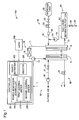
- Fig. 1 is a schematic diagram showing a configuration of a fuel cell system 100.
- the fuel cell system 100 includes a fuel cell 10, a controller 20, a cathode gas supply portion 30, a cathode gas discharge portion 40, an anode gas supply portion 50, an anode gas circulation discharge portion 60 and a coolant supply portion 70.
- the fuel cell 10 is a solid polymer-type fuel cell that receives the supply of hydrogen (anode gas) and air (cathode gas) serving as reaction gases to perform power generation.
- the fuel cell 10 has a stack structure in which a plurality of (for example, 400) cells 11 are stacked in layers.
- Each of the cells 11 includes a membrane electrode joint member that is a power generation member in which electrodes are arranged on both surfaces of an electrolyte membrane, and two separators that sandwich the membrane electrode joint member.
- the electrolyte membrane is formed with a solid polymer thin film that indicates satisfactory proton conductivity in a wet state.
- the electrode is formed of carbon.
- a platinum catalyst for facilitating a power generation reaction is carried.
- a manifold (not shown) for the reaction gas and the coolant is provided in each of the cells 11. The reaction gas in the manifold is supplied through a gas flow path provided in each of the cells 11 to the power generation region of each of the cells 11.
- the controller 20 includes a power generation controller 300 and a priority instructor 400.
- the power generation controller 300 includes a first control unifier 310, a second control unifier 320 and a selector 330.
- the controller 20 receives a power generation requirement from a load 200, controls, according to the requirement, the individual constituent portions of the fuel cell system 100 which will be described below and thereby realizes the power generation with the fuel cell 10.
- the cathode gas supply portion 30 includes a cathode gas pipe 31, an air compressor 32 and an opening/closing valve 34.
- the cathode gas pipe 31 is a pipe that is connected to the cathode side of the fuel cell 10.
- the air compressor 32 is connected to the fuel cell 10 through the cathode gas pipe 31, takes in outside air and supplies the compressed air to the fuel cell 10 as the cathode gas.
- the controller 20 drives the air compressor 32 to control the amount of air supplied to the fuel cell 10 either by associating it with power supply to the load 200 or independently of the power supply.
- the opening/closing valve 34 is provided between the air compressor 32 and the fuel cell 10, and is opened or closed according to the flow of the supplied air in the cathode gas pipe 31. Specifically, the opening/closing valve 34 is normally closed, and is opened when the air compressor 32 supplies air having a predetermined pressure to the cathode gas pipe 31.
- the cathode gas discharge portion 40 includes a cathode exhaust gas pipe 41 and a pressure adjustment valve 43.
- the cathode exhaust gas pipe 41 is a pipe that is connected to the cathode side of the fuel cell 10, and discharges a cathode exhaust gas to the outside of the fuel cell system 100.
- the pressure adjustment valve 43 adjusts the pressure (the back pressure of the fuel cell 10) of the cathode exhaust gas in the cathode exhaust gas pipe 41.
- the anode gas supply portion 50 includes an anode gas pipe 51, a hydrogen tank 52, an opening/closing valve 53, a regulator 54 and an injector 55.
- the hydrogen tank 52 is connected to the anode of the fuel cell 10 through the anode gas pipe 51, and supplies hydrogen filled in the tank to the fuel cell 10.
- the opening/closing valve 53, the regulator 54 and the injector 55 are provided in the anode gas pipe 51 in this order from the upstream side (that is, the side close to the hydrogen tank 52).
- the opening/closing valve 53 is opened or closed by an instruction from the controller 20 to control the flow of hydrogen from the hydrogen tank 52 into the upstream side of the injector 55.
- the regulator 54 is a pressure reduction value for adjusting the pressure of hydrogen on the upstream side of the injector 55.
- the injector 55 is an electromagnetically driven opening/closing valve in which a valve member is electromagnetically driven according to a drive period and a valve opening time set by the controller 20.
- the controller 20 controls the drive period and the valve opening time of the injector 55 to control the amount of hydrogen supplied to the fuel cell 10.
- the anode gas circulation discharge portion 60 includes an anode exhaust gas pipe 61, a gas-liquid separation portion 62, an anode gas circulation pipe 63, a hydrogen circulation pipe 64, an anode drain pipe 65 and a drain valve 66.
- the anode exhaust gas pipe 61 is a pipe that connects the outlet of the anode of the fuel cell 10 to the gas-liquid separation portion 62, and guides an anode exhaust gas containing unreacted gases (hydrogen, nitrogen and the like) which are not used in the power generation reaction to the gas-liquid separation portion 62.
- the gas-liquid separation portion 62 is connected to the anode gas circulation pipe 63 and the anode drain pipe 65.
- the gas-liquid separation portion 62 separates gas components and moisture contained in the anode exhaust gas, guides the gas components to the anode gas circulation pipe 63 and guides the moisture to the anode drain pipe 65.
- the anode gas circulation pipe 63 is connected to the downstream side of the injector 55 of the anode gas pipe 51.
- the hydrogen circulation pipe 64 is provided, and through the hydrogen circulation pipe 64, the hydrogen contained in the gas components separated in the gas-liquid separation portion 62 is fed out to the anode gas pipe 51.
- the hydrogen contained in the anode exhaust gas is circulated and is supplied again to the fuel cell 10, with the result that the efficiency of utilization of hydrogen is enhanced.
- the anode drain pipe 65 is a pipe for discharging the moisture separated in the gas-liquid separation portion 62 to the outside of the fuel cell system 100.
- the drain valve 66 is provided in the anode drain pipe 65, and is opened or closed according to an instruction from the controller 20.
- the controller 20 normally closes the drain valve 66 while the fuel cell system 100 is being operated, and opens the drain valve 66 at predetermined drain timing previously set or at timing at which an inert gas in the anode exhaust gas is discharged.
- the coolant supply portion 70 includes a coolant pipe 71, a radiator 72 and a coolant circulation pump 73.
- the coolant pipe 71 is a pipe that couples a coolant inlet manifold and a coolant outlet manifold provided in the fuel cell 10, and circulates the coolant for cooling the fuel cell 10.
- the radiator 72 is provided in the coolant pipe 71, and performs heat exchange between the coolant flowing through the coolant pipe 71 and the outside air to cool the coolant.
- the coolant circulation pump 73 is provided in the coolant pipe 71 on the downstream side (the coolant inlet side of the fuel cell 10) of the radiator 72, and feeds out the coolant cooled in the radiator 72 to the fuel cell 10.
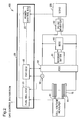
- Fig. 2 is a schematic diagram showing an electrical configuration of the fuel cell system 100.
- the fuel cell system 100 includes, in addition to the controller 20 and the like described previously, a secondary battery 81, an FDC 82, a DC/AC converter 83, a BDC 85, a cell voltage measurer 91 and a current measurer 92.
- the controller 20 includes a fuel cell ECU 21, an FDC-ECU 22 and a power control ECU 23.
- the fuel cell ECU 21, the FDC-ECU 22 and the power control ECU 23 communicate with each other through buses according to a communication protocol such as a CAN.
- the cell voltage measurer 91 is connected to each of the cells 11 of the fuel cell 10, and measures the voltage (cell voltage) of each of the cells 11.
- the cell voltage measurer 91 transmits the results of the measurements to the fuel cell ECU 21.
- the current measurer 92 measures the value of a generated current by the fuel cell 10, and transmits it to the fuel cell ECU 21 and the FDC-ECU 22.
- the power control ECU 23 acquires a required power value from the load 200, and reflects it on the operation of the fuel cell 10.
- the fuel cell ECU 21 controls the anode gas and the cathode gas based on the required power value, the cell voltage and the generated current. Specifically, the fuel cell ECU 21 controls the operations of the opening/closing valve 53, the hydrogen circulation pipe 64, the drain valve 66 and the like to control the flow rate of the anode gas, and controls the number of revolutions of the air compressor 32 and the like to control the flow rate of the cathode gas and the like.
- the FDC 82 and the BDC 85 are DC/DC converters.
- the FDC 82 controls, based on control by the FDC-ECU 22, the generated current and the generated voltage by the fuel cell 10, and changes the generated voltage to supply it to the DC/AC converter 83. Furthermore, the FDC 82 measures the generated voltage to transmit it to the FDC-ECU 22.
- the BDC 85 controls the charging and discharging of the secondary battery 81 based on control by another ECU (not illustrated) included in the controller 20.
- the secondary battery 81 is formed with a lithium-ion battery, and functions as an auxiliary power supply of the fuel cell 10.
- the DC/AC converter 83 is connected to the fuel cell 10 and the load 200.
- the DC/AC converter 83 converts direct-current power obtained by the fuel cell 10 and the secondary battery 81 into alternating-current power, and supplies it to the load 200.
- Regenerative power produced in the load 200 is converted by the DC/AC converter 83 into a direct current, and is charged by the BDC 85 in the secondary battery 81.
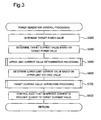
- Fig. 3 is a flowchart showing power generation control processing.
- the power generation control processing is performed in a coordinated manner by the fuel cell ECU 21, the FDC-ECU 22 and the power control ECU 23, and is repeatedly performed while power is being generated by the fuel cell 10.
- Fig. 3 and Figs. 6 and 7 which will be described later, each of the steps that are allocated and performed by the three ECUs are shown as a series of flowchart.
- the power control ECU 23 first determines a target power value Ptgt based on the required power from the load 200 (step S300). Then, the fuel cell ECU 21 determines a target current value Itgt based on the target power value Ptgt (step S400).
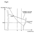
- Fig. 4 is a graph showing a current-voltage characteristic of the fuel cell 10. Specifically, this graph corresponds to a graph that is obtained by multiplying the vertical axis and the horizontal axis of a graph showing a current-voltage characteristic of one cell 11 by the number of cells 11 included in the fuel cell 10.
- Fig. 5 is an enlarged view of a region 5 shown in Fig. 4 .
- Power (W) is calculated as the product of current (A) and voltage (V).
- V voltage
- step S500 upper limit current value determination processing is performed (step S500).
- the controller 20 realizes the first control by performing the upper limit current value determination processing.
- Fig. 6 is a flowchart showing the upper limit current value determination processing.
- the power control ECU 23 first determines a first upper limit current value based on an upper limit power value Pmax (step S510).
- the power control ECU 23 realizes power control by performing step S510.
- the power control ECU 23 performs step S510 to function as the power generation controller 300 and the first control unifier 310.
- the upper limit power value Pmax is a variable that is determined by the power control ECU 23. For example, the determination of the upper limit power value Pmax is performed in order to protect the secondary battery 81.
- the secondary battery 81 may be degraded by being charged by a large amount of power or by being excessively charged.
- a first upper limit current value Imax1 is determined by formula (4) below.
- Pj represents an actual measured value of power
- Vj represents an actual measured value of voltage
- Itgtold represents an immediate target current value.
- the FDC-ECU 22 determines a second upper limit current value based on a lower limit voltage value Vmin (step S520).
- the FDC-ECU 22 performs step S520 to realize voltage control.
- the FDC-ECU 22 performs step S520 to function as the power generation controller 300 and the first control unifier 310.
- the lower limit voltage value Vmin is a value that indicates the lower limit value of the cell voltage, and is a variable that is determined by the fuel cell ECU 21. For example, the determination of the lower limit voltage value Vmin is performed so as to protect the fuel cell 10 and prevent the power generation efficiency from being lowered. When the cell voltage is excessively low, the temperature of the fuel cell 10 may be excessively increased.
- a second upper limit current value Imax2 is determined by formula (8) below.
- G1 represents a positive gain.
- the FDC-ECU 22 acquires a rated current Ir as a third upper limit current value Imax3 (step S530).
- the FDC-ECU 22 performs step S530 to realize current control.
- the FDC-ECU 22 performs step S530 to function as the power generation controller 300 and the first control unifier 310.
- the rated current Ir is a predetermined fixed value (for example, 500 A) so as to protect individual components through which current flows, and is stored in the FDC-ECU 22.
- the FDC-ECU 22 determines the minimum value of the first, second and third upper limit current values Imax1, Imax2 and Imax3 as a priority upper limit current value ImaxA (step S540).
- the FDC-ECU 22 performs step S540 to select the minimum value of the first, second and third upper limit current values Imax1, Imax2 and Imax3.
- the FDC-ECU 22 performs step S540 to function as the selector 330.
- the current value is controlled to be equal to or less than the priority upper limit current value ImaxA, and thus all the limitations by the first, second and third upper limit current values are satisfied. In other words, it is possible to satisfy all the following limitations: the generated power does not exceed the upper limit power value Pmax; the generated voltage does not fall below the lower limit voltage value Vmin; and the generated power does not exceed the rated current Ir.
- the fuel cell ECU 21 determines a non-priority upper limit current value ImaxB based on a stoichiometric ratio (step S550), and completes the upper limit current value determination processing.
- the fuel cell ECU 21 performs step S550 to realize third control.
- the fuel cell ECU 21 performs step S550 to function as the power generation controller 300.
- the non-priority upper limit current value ImaxB is a variable that is determined by the fuel cell ECU 21. As the generated current is increased, the flow rates necessary for the anode gas and the cathode gas are increased. However, there are upper limits of the flow rates for the anode gas and the cathode gas.
- step S550 in order to avoid such a situation, the upper limit value of the generated current is determined so as to prevent the stoichiometric ratio from being excessively decreased.
- the upper limit value is indicated as a current value Is in Fig. 5 .
- the FDC-ECU 22 determines a lower limit current value Imin based on an upper limit voltage value Vmax (step S600).
- the FDC-ECU 22 performs step S600 to realize second control.
- the FDC-ECU 22 performs step S600 to function as the power generation controller 300 and the second control unifier 320.
- the lower limit current value Imin is determined by formula (12) below.
- the upper limit voltage value Vmax is a variable that is determined by the fuel cell ECU 21, and for example, a value for suppressing the degradation of the cells 11 is adopted.
- G2 represents a positive gain. G2 may be same as or different from G1.
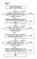
- Fig. 7 is a flowchart showing the target current value correction processing. Whether the target current value Itgt is equal to or less than the non-priority upper limit current value ImaxB is determined (step S710). When the target current value Itgt exceeds the non-priority upper limit current value ImaxB (no in step S710), a correction is made such that the target current value Itgt coincides with the non-priority upper limit current value ImaxB (step S720). On the other hand, when the target current value Itgt is equal to or less than the non-priority upper limit current value ImaxB (yes in step S710), step S720 is skipped.
- step S730 whether the target current value Itgt is equal to or more than the lower limit current value Imin is determined. In other words, whether or not the second control collides with the third control is determined.
- the target current value Itgt is less than the lower limit current value Imin (no in step S730)
- a correction is made such that the target current value Itgt becomes equal to the lower limit current value Imin (step S740).
- step S740 is skipped.
- step S750 whether the target current value Itgt is equal to or less than the priority upper limit current value ImaxA is determined. In other words, whether or not the first control collides with the second control is determined.
- the target current value Itgt exceeds the priority upper limit current value ImaxA (no in step S750)
- a correction is made such that the target current value Itgt coincides with the priority upper limit current value ImaxA (step S760), and the target current value correction processing is completed.
- step S760 is skipped, and the target current value correction processing is completed.
- the FDC-ECU 22 controls the FDC 82 such that the generated current is made close to the target current value Itgt (step S800).
- the target current value Itgt in the stage of step S800 and the voltage value corresponding to the target current value Itgt are adopted as the operation point of the fuel cell 10.
- the FDC-ECU 22 performs S800 to function as the power generation controller 300. That step S760 is performed corresponds to that the power generation controller 300 functioned by the performance of step S800 is instructed to prioritize the first control over the second control. In other words, the FDC-ECU 22 functions as the priority instructor 400 by the performance of step S760.
- step S760 When step S760 is not performed, the performance of step S740 corresponds to the instruction of prioritizing the second control over the third control with respect to the power generation controller 300 functioned by the performance of step S800. In other words, when step S760 is not performed, the FDC-ECU 22 functions as the priority instructor 400 by the performance of step S740.
- the power generation control processing described above it is possible to determine the control contents without performing complicated arbitration and the like for the limitations of the generated power, the generated voltage and the generated current.
- the determination can be easily performed as described above because the limitation values (the upper limit value and the lower limit value) are unified into currents and are compared and that furthermore, when the limitation values collide with each other, priority rules are applied.
- the priority rules mean the contents realized by the target current value correction processing ( Fig. 7 ).
- the highest priority is that the current value does not exceed the priority upper limit current value ImaxA (steps S750 and S760)
- the second highest priority is that the current value does not fall below the lower limit current value Imin (steps S730 and S740)
- subsequent to these two conditions is that the current value does not exceed the non-priority upper limit current value ImaxB (steps S710 and S720).
- the initial current target value is determined to be the target current value Itgt without being processed, with the result that all the requirements are satisfied and that the required power value is also satisfied.
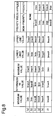
- Fig. 8 shows a table for illustrating the applications of the priority rules.
- the minimum value, the intermediate value and the maximum value show a magnitude relationship between the priority upper limit current value ImaxA, the non-priority upper limit current value ImaxB and the lower limit current value Imin determined in the power generation control processing, and 6 ways of (a) to (f) shown in Fig. 8 can be considered.
- the intermediate value is not limited to the average value of the minimum value and the maximum value, and means a value that falls within a range equal to or more than the minimum value and equal to or less than the maximum value.
- the lower limit value and the upper limit value shown in Fig. 8 indicate a range that can be obtained as the target current value Itgt in step S800.
- the "applied priority rule" shown in Fig. 8 indicates the priority rule that is applied when the lower limit value and the upper limit value are determined from the magnitude relationship described above.
- Fig. 8(a) is applicable to the case illustrated both in Figs. 4 and 5 .
- the target current value Itgt is set equal to or more than the lower limit current value Imin and equal to or less than the priority upper limit current value ImaxA, no priority rule is applicable.
- the target current value Itgt is set equal to or more than the lower limit current value Imin and equal to or less than the non-priority upper limit current value ImaxB, no priority rule is applicable.
- the present invention is not limited to the embodiment, examples and variations in the present specification, and can be realized in various configurations without departing from the spirit thereof.
- the technical features of the embodiment, examples and variations corresponding to the technical features in the aspects described in the section of Summary of the Invention can be replaced or combined as necessary so that part or the whole of the problem described previously is solved or part or the whole of the effects described previously is achieved.
- the technical features are not described as essential features in the present specification, they can be deleted as necessary. For example, the followings will be illustrated.
- the allocating of the power generation control processing may be changed in any way.
- the allocating of the power generation control processing refers to the allocation of which of the ECUs performs each step in the power generation control processing.
- the number of control devices that perform the steps in the power generation control processing may be changed in any way.
- one ECU may perform all the steps or two or four or more ECUs may perform them in a coordinated manner.
- the priority upper limit current value may be determined.
- a current value for ensuring a stoichiometric ratio equal to or more than a predetermined value may be added to the determination of the priority upper limit current value.
- the non-priority upper limit current value may not be determined.
- the upper limit value of the target current value may be a value that cannot ensure a stoichiometric ratio equal to or more than a predetermined value.
- the non-priority upper limit current value and the lower limit current value consideration may be given to other parameters. For example, when it is impossible to suppress an increase in the temperature of the fuel cell by cooling with the cooling water, in order to limit the generated current, the temperature of the fuel cell may be added to the determination of the non-priority upper limit current value.
- the physical quantity into which the limitation values are unified may not be current.
- voltage or power may be used.
- the limitation values may not be unified into the same physical quantity.
- a method of utilizing a table may be used. Specifically, a table is previously produced in which when various limitation values and the target power value are substituted, the corrected target power value is output, and is stored in the FDC-ECU 22, and thus it is not necessary to unify the physical quantities.
- control utilizing a compromise may be performed.
- the target current value may be set equal to or more than ImaxA and equal to or less than Imin.
- weighting corresponding to the priority may be performed.
- the target current value may be set at a value that is closer to ImaxA having a high priority than to Imin having a low priority.
- the contents of the priority rules may be changed.
- the lower limit current value may be most prioritized.
- the upper limit current value for ensuring a stoichiometric ratio equal to or more than a predetermined value may be prioritized over the lower limit current value.
- the various limitation values (for example, the upper limit power value and the lower limit voltage value) described as variables may be fixed values that are previously determined.
- the targeted fuel cell does not need to be one for an automobile, and may be mounted on another transportation device (such as a motorcycle or a train) or may be installed.
- At least part of the function and processing realized by software may be realized by hardware.
- at least part of the function and processing realized by hardware may be realized by software.
- Examples of the hardware that can be used include an integrated circuit, a discrete circuit, a circuit module obtained by combining those circuits and various types of circuits (circuitry).
Abstract
Description
- This application claims priority based on
Japanese Patent Application No. 2014-229381 filed on November 12, 2014 - The present invention relates to fuel cells.
- In order to control power generation performed by a fuel cell, a configuration in which a plurality of ECUs are incorporated is known. Each of these ECUs determines the target ranges of various types of physical quantities so as to perform control allocated to itself (
JP2006-139972 - In the conventional technology described above, sufficient consideration is not given to a case where not all the target ranges determined by the ECUs are satisfied and thus pieces of control collide with each other. Such a problem is common not only to the case where each of the ECUs performs control allocated but also to a case where these pieces of control are unified into one ECU. In view of the foregoing problem, the present invention provides a control method in a case where in the control of a fuel cell, pieces of control on various types of physical quantities collide with each other.
- The present invention is made so as to solve the above problem, and can be realized as aspects below.
- According to one aspect of the present invention, there is provided a fuel cell system in which power generation is performed by a fuel cell. The fuel cell system includes: a power generation controller that performs: first control in which at least one of power control for preventing generated power from exceeding an upper limit value, voltage control for preventing generated voltage from falling below a lower limit value and current control for preventing generated current from exceeding an upper limit value is performed and second control in which the generated voltage is prevented from exceeding an upper limit value; and a priority instructor that instructs the power generation controller to prioritize the first control as compared with the second control when the first control and the second control collide with each other. According to this aspect, when the first control and the second control collide with each other, it is possible to determine the control contents without performing complicated arbitration and the like. Furthermore, by prioritizing the first control over the second control, conditions which should be further avoided can be avoided.
- In the aspect described above, the power generation controller may further perform third control in which for at least one of an anode and a cathode, a stoichiometric ratio is prevented from falling below a predetermined value, and the priority instructor may instruct the power generation controller to prioritize the second control over the third control when the second control and the third control collide with each other. According to this aspect, when the second control and the third control collide with each other, it is possible to determine the control contents without performing complicated arbitration and the like.
- In the aspect described above, the fuel cell system may further include a plurality of control devices that communicate with each other, where the plurality of control devices may allocate and perform the power control, the voltage control, the current control, the second control and the instruction. According to this aspect, when the control devices allocate and perform the control, the aspect described above can be applied.
- In the aspect described above, the power generation controller may perform, as the first control, at least two of the power control, the voltage control and the current control, and the power generation controller may include: a first control unifier that unifies values used in the first control among the upper limit value of the generated power, the lower limit value of the generated voltage and the upper limit value of the generated current into the same physical quantity; and a selector that selects, as a limitation value in the first control, a value for realizing the first control among the values after the unification. In this aspect, the first control can easily be realized.
- In the aspect described above, the power generation controller may include a second control unifier that unifies the upper limit value of the generated voltage into the physical quantity, and when a limitation value unified by the second control unifier collides with the limitation value selected by the selector, the priority instructor may determine that the first control and the second control collide with each other. According to this aspect, it can easily be determined that the first control and the second control collide with each other.
- In the aspect described above, the physical quantity may be current. In this aspect, it can easily be determined that the first control and the second control collide with each other.
- The present invention can be realized in various aspects other than the aspects described above. For example, the present invention can be realized in aspects such as a method of controlling a fuel cell, a control device that realizes this method, a computer program for realizing this method and a permanent storage medium that stores this computer program, and the like.
-
-
Fig. 1 is a schematic diagram showing a configuration of a fuel cell system: -
Fig. 2 is a schematic diagram showing an electrical configuration of the fuel cell system; -
Fig. 3 is a flowchart showing power generation control processing; -
Fig. 4 is a graph showing a current-voltage characteristic; -
Fig. 5 is an enlarged view of the above graph; -
Fig. 6 is a flowchart showing upper limit current value determination processing; -
Fig. 7 is a flowchart showing target current value correction processing; and -
Fig. 8 is a table for the application of priority rules. -
Fig. 1 is a schematic diagram showing a configuration of afuel cell system 100. Thefuel cell system 100 includes afuel cell 10, acontroller 20, a cathodegas supply portion 30, a cathodegas discharge portion 40, an anodegas supply portion 50, an anode gascirculation discharge portion 60 and acoolant supply portion 70. - The
fuel cell 10 is a solid polymer-type fuel cell that receives the supply of hydrogen (anode gas) and air (cathode gas) serving as reaction gases to perform power generation. Thefuel cell 10 has a stack structure in which a plurality of (for example, 400)cells 11 are stacked in layers. Each of thecells 11 includes a membrane electrode joint member that is a power generation member in which electrodes are arranged on both surfaces of an electrolyte membrane, and two separators that sandwich the membrane electrode joint member. - The electrolyte membrane is formed with a solid polymer thin film that indicates satisfactory proton conductivity in a wet state. The electrode is formed of carbon. On the surface on the electrolyte membrane side of the electrode, a platinum catalyst for facilitating a power generation reaction is carried. In each of the
cells 11, a manifold (not shown) for the reaction gas and the coolant is provided. The reaction gas in the manifold is supplied through a gas flow path provided in each of thecells 11 to the power generation region of each of thecells 11. - The
controller 20 includes apower generation controller 300 and apriority instructor 400. Thepower generation controller 300 includes afirst control unifier 310, a second control unifier 320 and aselector 330. Thecontroller 20 receives a power generation requirement from aload 200, controls, according to the requirement, the individual constituent portions of thefuel cell system 100 which will be described below and thereby realizes the power generation with thefuel cell 10. - The cathode
gas supply portion 30 includes acathode gas pipe 31, anair compressor 32 and an opening/closing valve 34. Thecathode gas pipe 31 is a pipe that is connected to the cathode side of thefuel cell 10. Theair compressor 32 is connected to thefuel cell 10 through thecathode gas pipe 31, takes in outside air and supplies the compressed air to thefuel cell 10 as the cathode gas. Thecontroller 20 drives theair compressor 32 to control the amount of air supplied to thefuel cell 10 either by associating it with power supply to theload 200 or independently of the power supply. - The opening/
closing valve 34 is provided between theair compressor 32 and thefuel cell 10, and is opened or closed according to the flow of the supplied air in thecathode gas pipe 31. Specifically, the opening/closing valve 34 is normally closed, and is opened when theair compressor 32 supplies air having a predetermined pressure to thecathode gas pipe 31. - The cathode
gas discharge portion 40 includes a cathodeexhaust gas pipe 41 and apressure adjustment valve 43. The cathodeexhaust gas pipe 41 is a pipe that is connected to the cathode side of thefuel cell 10, and discharges a cathode exhaust gas to the outside of thefuel cell system 100. Thepressure adjustment valve 43 adjusts the pressure (the back pressure of the fuel cell 10) of the cathode exhaust gas in the cathodeexhaust gas pipe 41. - The anode
gas supply portion 50 includes ananode gas pipe 51, ahydrogen tank 52, an opening/closing valve 53, aregulator 54 and aninjector 55. Thehydrogen tank 52 is connected to the anode of thefuel cell 10 through theanode gas pipe 51, and supplies hydrogen filled in the tank to thefuel cell 10. - The opening/
closing valve 53, theregulator 54 and theinjector 55 are provided in theanode gas pipe 51 in this order from the upstream side (that is, the side close to the hydrogen tank 52). The opening/closing valve 53 is opened or closed by an instruction from thecontroller 20 to control the flow of hydrogen from thehydrogen tank 52 into the upstream side of theinjector 55. Theregulator 54 is a pressure reduction value for adjusting the pressure of hydrogen on the upstream side of theinjector 55. - The
injector 55 is an electromagnetically driven opening/closing valve in which a valve member is electromagnetically driven according to a drive period and a valve opening time set by thecontroller 20. Thecontroller 20 controls the drive period and the valve opening time of theinjector 55 to control the amount of hydrogen supplied to thefuel cell 10. - The anode gas
circulation discharge portion 60 includes an anodeexhaust gas pipe 61, a gas-liquid separation portion 62, an anodegas circulation pipe 63, ahydrogen circulation pipe 64, ananode drain pipe 65 and adrain valve 66. The anodeexhaust gas pipe 61 is a pipe that connects the outlet of the anode of thefuel cell 10 to the gas-liquid separation portion 62, and guides an anode exhaust gas containing unreacted gases (hydrogen, nitrogen and the like) which are not used in the power generation reaction to the gas-liquid separation portion 62. - The gas-
liquid separation portion 62 is connected to the anodegas circulation pipe 63 and theanode drain pipe 65. The gas-liquid separation portion 62 separates gas components and moisture contained in the anode exhaust gas, guides the gas components to the anodegas circulation pipe 63 and guides the moisture to theanode drain pipe 65. - The anode
gas circulation pipe 63 is connected to the downstream side of theinjector 55 of theanode gas pipe 51. In the anodegas circulation pipe 63, thehydrogen circulation pipe 64 is provided, and through thehydrogen circulation pipe 64, the hydrogen contained in the gas components separated in the gas-liquid separation portion 62 is fed out to theanode gas pipe 51. As described above, in thefuel cell system 100, the hydrogen contained in the anode exhaust gas is circulated and is supplied again to thefuel cell 10, with the result that the efficiency of utilization of hydrogen is enhanced. - The
anode drain pipe 65 is a pipe for discharging the moisture separated in the gas-liquid separation portion 62 to the outside of thefuel cell system 100. Thedrain valve 66 is provided in theanode drain pipe 65, and is opened or closed according to an instruction from thecontroller 20. Thecontroller 20 normally closes thedrain valve 66 while thefuel cell system 100 is being operated, and opens thedrain valve 66 at predetermined drain timing previously set or at timing at which an inert gas in the anode exhaust gas is discharged. - The
coolant supply portion 70 includes acoolant pipe 71, aradiator 72 and acoolant circulation pump 73. Thecoolant pipe 71 is a pipe that couples a coolant inlet manifold and a coolant outlet manifold provided in thefuel cell 10, and circulates the coolant for cooling thefuel cell 10. Theradiator 72 is provided in thecoolant pipe 71, and performs heat exchange between the coolant flowing through thecoolant pipe 71 and the outside air to cool the coolant. - The
coolant circulation pump 73 is provided in thecoolant pipe 71 on the downstream side (the coolant inlet side of the fuel cell 10) of theradiator 72, and feeds out the coolant cooled in theradiator 72 to thefuel cell 10. -
Fig. 2 is a schematic diagram showing an electrical configuration of thefuel cell system 100. Thefuel cell system 100 includes, in addition to thecontroller 20 and the like described previously, asecondary battery 81, anFDC 82, a DC/AC converter 83, aBDC 85, acell voltage measurer 91 and acurrent measurer 92. Thecontroller 20 includes afuel cell ECU 21, an FDC-ECU 22 and apower control ECU 23. Thefuel cell ECU 21, the FDC-ECU 22 and thepower control ECU 23 communicate with each other through buses according to a communication protocol such as a CAN. - The
cell voltage measurer 91 is connected to each of thecells 11 of thefuel cell 10, and measures the voltage (cell voltage) of each of thecells 11. Thecell voltage measurer 91 transmits the results of the measurements to thefuel cell ECU 21. Thecurrent measurer 92 measures the value of a generated current by thefuel cell 10, and transmits it to thefuel cell ECU 21 and the FDC-ECU 22. - The
power control ECU 23 acquires a required power value from theload 200, and reflects it on the operation of thefuel cell 10. Thefuel cell ECU 21 controls the anode gas and the cathode gas based on the required power value, the cell voltage and the generated current. Specifically, thefuel cell ECU 21 controls the operations of the opening/closingvalve 53, thehydrogen circulation pipe 64, thedrain valve 66 and the like to control the flow rate of the anode gas, and controls the number of revolutions of theair compressor 32 and the like to control the flow rate of the cathode gas and the like. - The
FDC 82 and theBDC 85 are DC/DC converters. TheFDC 82 controls, based on control by the FDC-ECU 22, the generated current and the generated voltage by thefuel cell 10, and changes the generated voltage to supply it to the DC/AC converter 83. Furthermore, theFDC 82 measures the generated voltage to transmit it to the FDC-ECU 22. TheBDC 85 controls the charging and discharging of thesecondary battery 81 based on control by another ECU (not illustrated) included in thecontroller 20. Thesecondary battery 81 is formed with a lithium-ion battery, and functions as an auxiliary power supply of thefuel cell 10. - The DC/
AC converter 83 is connected to thefuel cell 10 and theload 200. The DC/AC converter 83 converts direct-current power obtained by thefuel cell 10 and thesecondary battery 81 into alternating-current power, and supplies it to theload 200. Regenerative power produced in theload 200 is converted by the DC/AC converter 83 into a direct current, and is charged by theBDC 85 in thesecondary battery 81. -
Fig. 3 is a flowchart showing power generation control processing. The power generation control processing is performed in a coordinated manner by thefuel cell ECU 21, the FDC-ECU 22 and thepower control ECU 23, and is repeatedly performed while power is being generated by thefuel cell 10. InFig. 3 andFigs. 6 and7 , which will be described later, each of the steps that are allocated and performed by the three ECUs are shown as a series of flowchart. - The
power control ECU 23 first determines a target power value Ptgt based on the required power from the load 200 (step S300). Then, thefuel cell ECU 21 determines a target current value Itgt based on the target power value Ptgt (step S400). -
Fig. 4 is a graph showing a current-voltage characteristic of thefuel cell 10. Specifically, this graph corresponds to a graph that is obtained by multiplying the vertical axis and the horizontal axis of a graph showing a current-voltage characteristic of onecell 11 by the number ofcells 11 included in thefuel cell 10.Fig. 5 is an enlarged view of a region 5 shown inFig. 4 . Power (W) is calculated as the product of current (A) and voltage (V). In step S400, a current value at an intersection (not illustrated) between a curve (hereinafter referred to as a "characteristic curve") showing a current-voltage characteristic and V = Ptgt / I is determined as the target current value Itgt. - Then, upper limit current value determination processing is performed (step S500). The
controller 20 realizes the first control by performing the upper limit current value determination processing.Fig. 6 is a flowchart showing the upper limit current value determination processing. Thepower control ECU 23 first determines a first upper limit current value based on an upper limit power value Pmax (step S510). Thepower control ECU 23 realizes power control by performing step S510. Thepower control ECU 23 performs step S510 to function as thepower generation controller 300 and thefirst control unifier 310. The upper limit power value Pmax is a variable that is determined by thepower control ECU 23. For example, the determination of the upper limit power value Pmax is performed in order to protect thesecondary battery 81. Thesecondary battery 81 may be degraded by being charged by a large amount of power or by being excessively charged. - In step S510, a first upper limit current value Imax1 is determined by formula (4) below. In the following formulas, Pj represents an actual measured value of power, Vj represents an actual measured value of voltage and Itgtold represents an immediate target current value.


- Then, the FDC-
ECU 22 determines a second upper limit current value based on a lower limit voltage value Vmin (step S520). The FDC-ECU 22 performs step S520 to realize voltage control. The FDC-ECU 22 performs step S520 to function as thepower generation controller 300 and thefirst control unifier 310. The lower limit voltage value Vmin is a value that indicates the lower limit value of the cell voltage, and is a variable that is determined by thefuel cell ECU 21. For example, the determination of the lower limit voltage value Vmin is performed so as to protect thefuel cell 10 and prevent the power generation efficiency from being lowered. When the cell voltage is excessively low, the temperature of thefuel cell 10 may be excessively increased. When the cell voltage is excessively low, it may enter the operation region in which as the cell voltage is lowered, generated power is lowered, and thus the power generation efficiency may be lowered. In step S520, a second upper limit current value Imax2 is determined by formula (8) below. In the following formula, G1 represents a positive gain.


- Then, the FDC-
ECU 22 acquires a rated current Ir as a third upper limit current value Imax3 (step S530). The FDC-ECU 22 performs step S530 to realize current control. The FDC-ECU 22 performs step S530 to function as thepower generation controller 300 and thefirst control unifier 310. The rated current Ir is a predetermined fixed value (for example, 500 A) so as to protect individual components through which current flows, and is stored in the FDC-ECU 22. - Then, the FDC-
ECU 22 determines the minimum value of the first, second and third upper limit current values Imax1, Imax2 and Imax3 as a priority upper limit current value ImaxA (step S540). The FDC-ECU 22 performs step S540 to select the minimum value of the first, second and third upper limit current values Imax1, Imax2 and Imax3. Hence, the FDC-ECU 22 performs step S540 to function as theselector 330. The current value is controlled to be equal to or less than the priority upper limit current value ImaxA, and thus all the limitations by the first, second and third upper limit current values are satisfied. In other words, it is possible to satisfy all the following limitations: the generated power does not exceed the upper limit power value Pmax; the generated voltage does not fall below the lower limit voltage value Vmin; and the generated power does not exceed the rated current Ir. - Then, the
fuel cell ECU 21 determines a non-priority upper limit current value ImaxB based on a stoichiometric ratio (step S550), and completes the upper limit current value determination processing. Thefuel cell ECU 21 performs step S550 to realize third control. Thefuel cell ECU 21 performs step S550 to function as thepower generation controller 300. The non-priority upper limit current value ImaxB is a variable that is determined by thefuel cell ECU 21. As the generated current is increased, the flow rates necessary for the anode gas and the cathode gas are increased. However, there are upper limits of the flow rates for the anode gas and the cathode gas. Hence, when the generated current is excessively increased, the stoichiometric ratio falls below a normal range. In step S550, in order to avoid such a situation, the upper limit value of the generated current is determined so as to prevent the stoichiometric ratio from being excessively decreased. The upper limit value is indicated as a current value Is inFig. 5 . - Then, as shown in
Fig. 3 , the FDC-ECU 22 determines a lower limit current value Imin based on an upper limit voltage value Vmax (step S600). The FDC-ECU 22 performs step S600 to realize second control. The FDC-ECU 22 performs step S600 to function as thepower generation controller 300 and thesecond control unifier 320. Specifically, the lower limit current value Imin is determined by formula (12) below. The upper limit voltage value Vmax is a variable that is determined by thefuel cell ECU 21, and for example, a value for suppressing the degradation of thecells 11 is adopted. In the following formula, G2 represents a positive gain. G2 may be same as or different from G1.


- Then, the FDC-
ECU 22 performs target current value correction processing (step S700).Fig. 7 is a flowchart showing the target current value correction processing. Whether the target current value Itgt is equal to or less than the non-priority upper limit current value ImaxB is determined (step S710). When the target current value Itgt exceeds the non-priority upper limit current value ImaxB (no in step S710), a correction is made such that the target current value Itgt coincides with the non-priority upper limit current value ImaxB (step S720). On the other hand, when the target current value Itgt is equal to or less than the non-priority upper limit current value ImaxB (yes in step S710), step S720 is skipped. - Then, whether the target current value Itgt is equal to or more than the lower limit current value Imin is determined (step S730). In other words, whether or not the second control collides with the third control is determined. When the target current value Itgt is less than the lower limit current value Imin (no in step S730), it is determined that the second control collides with the third control. Hence, when the target current value Itgt is less than the lower limit current value Imin (no in step S730), a correction is made such that the target current value Itgt becomes equal to the lower limit current value Imin (step S740). On the other hand, when the target current value Itgt is equal to or more than the lower limit current value Imin (yes in step S730), step S740 is skipped.
- Then, whether the target current value Itgt is equal to or less than the priority upper limit current value ImaxA is determined (step S750). In other words, whether or not the first control collides with the second control is determined. When the target current value Itgt exceeds the priority upper limit current value ImaxA (no in step S750), it is determined that the first control collides with the second control. Hence, when the target current value Itgt exceeds the priority upper limit current value ImaxA (no in step S750), a correction is made such that the target current value Itgt coincides with the priority upper limit current value ImaxA (step S760), and the target current value correction processing is completed. On the other hand, when the target current value Itgt is equal to or less than the priority upper limit current value ImaxA (yes in step S750), step S760 is skipped, and the target current value correction processing is completed.
- Finally, as shown in
Fig. 3 , the FDC-ECU 22 controls theFDC 82 such that the generated current is made close to the target current value Itgt (step S800). In other words, the target current value Itgt in the stage of step S800 and the voltage value corresponding to the target current value Itgt are adopted as the operation point of thefuel cell 10. The FDC-ECU 22 performs S800 to function as thepower generation controller 300. That step S760 is performed corresponds to that thepower generation controller 300 functioned by the performance of step S800 is instructed to prioritize the first control over the second control. In other words, the FDC-ECU 22 functions as thepriority instructor 400 by the performance of step S760. When step S760 is not performed, the performance of step S740 corresponds to the instruction of prioritizing the second control over the third control with respect to thepower generation controller 300 functioned by the performance of step S800. In other words, when step S760 is not performed, the FDC-ECU 22 functions as thepriority instructor 400 by the performance of step S740. - In the power generation control processing described above, it is possible to determine the control contents without performing complicated arbitration and the like for the limitations of the generated power, the generated voltage and the generated current. The determination can be easily performed as described above because the limitation values (the upper limit value and the lower limit value) are unified into currents and are compared and that furthermore, when the limitation values collide with each other, priority rules are applied. The priority rules mean the contents realized by the target current value correction processing (
Fig. 7 ). Specifically, the highest priority is that the current value does not exceed the priority upper limit current value ImaxA (steps S750 and S760), the second highest priority is that the current value does not fall below the lower limit current value Imin (steps S730 and S740), and subsequent to these two conditions is that the current value does not exceed the non-priority upper limit current value ImaxB (steps S710 and S720). - For example, it is assumed that a current value Ip at an intersection between the characteristic curve and V = Pmax / I (
Figs. 4 and5 ) coincides with the priority upper limit current value ImaxA, that a current value Ivmax at an intersection between the characteristic curve and V = Vmax coincides with the lower limit current value Imin and that the current value Ip is more than the lower limit current value Imin. In this case, control is performed such that the generated current falls within a range equal to or more than the current vale Ivmax and equal to or less than the current value Ip, and thus it is possible to perform control such that all the requirements of the priority upper limit current value ImaxA, the non-priority upper limit current value ImaxB and the lower limit current value Imin are satisfied. For example, when the target current value Itgt (hereinafter referred to as an "initial target current value" based on the target power value Ptgt falls within a range equal to or more than the current value Ivmax and equal to or less than the current value Ip, the initial current target value is determined to be the target current value Itgt without being processed, with the result that all the requirements are satisfied and that the required power value is also satisfied. On the other hand, when the initial target current value is less than the current value Ivmax, a correction is made such that the target current value Itgt coincides with the current value Ivmax whereas when the initial target current value exceeds the current value Ip, a correction is made such that the target current value Itgt coincides with the current value Ip, with the result that all the requirements are satisfied. In other words, in such a case, since the pieces of control do not collide with each other, the priority rules described above are not applied. Hence, a description of in which case the priority rules are applied will be given. -
Fig. 8 shows a table for illustrating the applications of the priority rules. The minimum value, the intermediate value and the maximum value show a magnitude relationship between the priority upper limit current value ImaxA, the non-priority upper limit current value ImaxB and the lower limit current value Imin determined in the power generation control processing, and 6 ways of (a) to (f) shown inFig. 8 can be considered. It is noted that the intermediate value is not limited to the average value of the minimum value and the maximum value, and means a value that falls within a range equal to or more than the minimum value and equal to or less than the maximum value. - The lower limit value and the upper limit value shown in
Fig. 8 indicate a range that can be obtained as the target current value Itgt in step S800. The "applied priority rule" shown inFig. 8 indicates the priority rule that is applied when the lower limit value and the upper limit value are determined from the magnitude relationship described above. -
Fig. 8(a) is applicable to the case illustrated both inFigs. 4 and5 . In this case, since as described previously, it is sufficient that the target current value Itgt is set equal to or more than the lower limit current value Imin and equal to or less than the priority upper limit current value ImaxA, no priority rule is applicable. - Even in the case of
Fig. 8(b) , it is sufficient that the target current value Itgt is set equal to or more than the lower limit current value Imin and equal to or less than the non-priority upper limit current value ImaxB, no priority rule is applicable. - In the case of
Fig. 8(c) , since the lower limit current value Imin is higher than the non-priority upper limit current value ImaxB, these two requirements cannot be satisfied and collide with each other. Hence, the requirement in which the target current value Itgt is set equal to or less than the non-priority upper limit current value ImaxB has a lower priority than the requirement in which the target current value Itgt is set equal to or more than the lower limit current value Imin, and is thus ignored. Consequently, the target current value Itgt is set equal to or more than the lower limit current value Imin and equal to or less than the priority upper limit current value ImaxA. - In the case of
Figs. 8(d) and (e) , since the priority upper limit current value ImaxA is lower than the lower limit current value Imin, these two requirements cannot be satisfied and collide with each other. Hence, the requirement in which the target current value Itgt is set equal to or more than the lower limit current value Imin has a lower priority than the requirement in which the target current value Itgt is set equal to or less than the priority upper limit current value ImaxA, and is thus ignored. However, the target current value Itgt is made to coincide with the priority upper limit current value ImaxA so that the target current value Itgt is as close to the lower limit current value Imin as possible. It is noted that in the case ofFig. 8(d) and (e) , the requirement in which the target current value Itgt is set equal to or less than the non-priority upper limit current value ImaxB is satisfied. - In the case of
Fig. 8(f) , since the priority upper limit current value ImaxA is less than the lower limit current value Imin, the requirement in which the target current value Itgt is set equal to or more than the lower limit current value Imin is ignored, and the target current value Itgt is set equal to or less than the priority upper limit current value ImaxA. On the other hand, since the lower limit current value Imin is higher than the non-priority upper limit current value ImaxB, the requirement in which the target current value Itgt is set equal to or less than the non-priority upper limit current value ImaxB is ignored, and the target current value Itgt is set as high as possible. Consequently, the target current value Itgt is made to coincide with the priority upper limit current value ImaxA. - Setting the target current value Itgt in the range equal to or more than the lower limit value and equal to or less than the upper limit value described as
Figs. 8(a) to (f) is realized by performing the target current value correction processing (Fig. 7 ) described previously. - In the embodiment described above, even under conditions in which it is impossible to satisfy all the requirements of the priority upper limit current value ImaxA, the non-priority upper limit current value ImaxB and the lower limit current value Imin, it is possible to perform appropriate control without degrading the responsivity.
- The present invention is not limited to the embodiment, examples and variations in the present specification, and can be realized in various configurations without departing from the spirit thereof. For example, the technical features of the embodiment, examples and variations corresponding to the technical features in the aspects described in the section of Summary of the Invention can be replaced or combined as necessary so that part or the whole of the problem described previously is solved or part or the whole of the effects described previously is achieved. When the technical features are not described as essential features in the present specification, they can be deleted as necessary. For example, the followings will be illustrated.
- The allocating of the power generation control processing may be changed in any way. The allocating of the power generation control processing refers to the allocation of which of the ECUs performs each step in the power generation control processing.
- The number of control devices that perform the steps in the power generation control processing may be changed in any way. For example, one ECU may perform all the steps or two or four or more ECUs may perform them in a coordinated manner.
- Without consideration given to any one or two of the upper limit power value, the lower limit voltage value and the rated current value, the priority upper limit current value may be determined. Alternatively, a current value for ensuring a stoichiometric ratio equal to or more than a predetermined value may be added to the determination of the priority upper limit current value.
- The non-priority upper limit current value may not be determined. In other words, the upper limit value of the target current value may be a value that cannot ensure a stoichiometric ratio equal to or more than a predetermined value.
- In the determination of the priority upper limit current value, the non-priority upper limit current value and the lower limit current value, consideration may be given to other parameters. For example, when it is impossible to suppress an increase in the temperature of the fuel cell by cooling with the cooling water, in order to limit the generated current, the temperature of the fuel cell may be added to the determination of the non-priority upper limit current value.
- The physical quantity into which the limitation values are unified may not be current. For example, voltage or power may be used.
- The limitation values may not be unified into the same physical quantity. For example, a method of utilizing a table may be used. Specifically, a table is previously produced in which when various limitation values and the target power value are substituted, the corrected target power value is output, and is stored in the FDC-
ECU 22, and thus it is not necessary to unify the physical quantities. - When two pieces of control collide with each other, instead of ignoring the control having a lower priority, control utilizing a compromise may be performed. For example, when the priority upper limit current value ImaxA is less than the lower limit current value Imin, the target current value may be set equal to or more than ImaxA and equal to or less than Imin. In this case, weighting corresponding to the priority may be performed. In other words, the target current value may be set at a value that is closer to ImaxA having a high priority than to Imin having a low priority.
- The contents of the priority rules may be changed. For example, the lower limit current value may be most prioritized. Alternatively, the upper limit current value for ensuring a stoichiometric ratio equal to or more than a predetermined value may be prioritized over the lower limit current value.
- The various limitation values (for example, the upper limit power value and the lower limit voltage value) described as variables may be fixed values that are previously determined.
- The current value at the intersection between the curve of V = Pmax / I and the characteristic curve may be determined as the first upper limit current value.
- The current value at the intersection between V = Vmin and the characteristic curve may be determined as the second upper limit current value.
- The current value at the intersection between V = Vmax and the characteristic curve may be determined as the lower limit current value.
- The targeted fuel cell does not need to be one for an automobile, and may be mounted on another transportation device (such as a motorcycle or a train) or may be installed.
- In the embodiment described above, at least part of the function and processing realized by software may be realized by hardware. Also, at least part of the function and processing realized by hardware may be realized by software. Examples of the hardware that can be used include an integrated circuit, a discrete circuit, a circuit module obtained by combining those circuits and various types of circuits (circuitry).
Claims (12)
- A fuel cell system in which power generation is performed by a fuel cell, comprising:a power generation controller that performs:first control in which at least one of power control for preventing generated power from exceeding an upper limit value, voltage control for preventing generated voltage from falling below a lower limit value and current control for preventing generated current from exceeding an upper limit value is performed andsecond control in which the generated voltage is prevented from exceeding an upper limit value; anda priority instructor that instructs the power generation controller to prioritize the first control over the second control when the first control and the second control collide with each other.
- The fuel cell system according to claim 1,
wherein the power generation controller further performs third control in which for at least one of an anode and a cathode, a stoichiometric ratio is prevented from falling below a predetermined value, and
the priority instructor instructs the power generation controller to prioritize the second control over the third control when the second control and the third control collide with each other. - The fuel cell system according to claim 1 or 2, further comprising:a plurality of control devices that communicate with each other,wherein the plurality of control devices allocate and perform the power control, the voltage control, the current control, the second control and the instruction.
- The fuel cell system according to any one of claims 1 to 3,
wherein the power generation controller performs, as the first control, at least two of the power control, the voltage control and the current control, and
the power generation controller includes:a first control unifier that unifies values used in the first control among the upper limit value of the generated power, the lower limit value of the generated voltage and the upper limit value of the generated current into a same physical quantity; anda selector that selects, as a limitation value in the first control, a value for realizing the first control among the values after the unification. - The fuel cell system according to claim 4,
wherein the power generation controller includes a second control unifier that unifies the upper limit value of the generated voltage into the physical quantity, and
when a limitation value unified by the second control unifier collides with the limitation value selected by the selector, the priority instructor determines that the first control and the second control collide with each other. - The fuel cell system according to claim 4 or 5,
wherein the physical quantity is current. - A method of controlling power generation performed by a fuel cell, the method comprising:performing first control in which at least one of power control for preventing generated power from exceeding an upper limit value, voltage control for preventing generated voltage from falling below a lower limit value and current control for preventing generated current from exceeding an upper limit value is performed and second control in which the generated voltage is prevented from exceeding an upper limit value; andprioritizing the first control over the second control when the first control and the second control collide with each other.
- The control method according to claim 7, further comprising:performing third control in which for at least one of an anode and a cathode, a stoichiometric ratio is prevented from falling below a predetermined value; andprioritizing the second control over the third control when the second control and the third control collide with each other.
- The control method according to claim 7 or 8,
wherein a plurality of control devices that communicate with each other allocate and perform the power control, the voltage control, the current control and the second control. - The control method according to any one of claims 7 to 9, further comprising:performing, as the first control, at least two of the power control, the voltage control and the current control; andunifying values used in the first control among the upper limit value of the generated power, the lower limit value of the generated voltage and the upper limit value of the generated current into a same physical quantity, and selecting, as a limitation value in the first control, a value for realizing the first control among the values after the unification.
- The control method according to claim 10, further comprising
determining that the first control and the second control collide with each other, when a limitation value unified by unifying the upper limit value of the generated voltage into the physical quantity and the selected limitation value collide with each other. - The control method according to claim 10 or 11,
wherein the physical quantity is current.
Applications Claiming Priority (1)
| Application Number | Priority Date | Filing Date | Title |
|---|---|---|---|
| JP2014229381A JP6183334B2 (en) | 2014-11-12 | 2014-11-12 | Fuel cell system and fuel cell control method |
Publications (2)
| Publication Number | Publication Date |
|---|---|
| EP3021399A1 true EP3021399A1 (en) | 2016-05-18 |
| EP3021399B1 EP3021399B1 (en) | 2019-11-27 |
Family
ID=54329458
Family Applications (1)
| Application Number | Title | Priority Date | Filing Date |
|---|---|---|---|
| EP15190004.0A Active EP3021399B1 (en) | 2014-11-12 | 2015-10-15 | Fuel cell system and method of controlling fuel cell |
Country Status (6)
| Country | Link |
|---|---|
| US (1) | US10359754B2 (en) |
| EP (1) | EP3021399B1 (en) |
| JP (1) | JP6183334B2 (en) |
| KR (1) | KR101847690B1 (en) |
| CN (1) | CN105591134B (en) |
| CA (1) | CA2909659C (en) |
Families Citing this family (1)
| Publication number | Priority date | Publication date | Assignee | Title |
|---|---|---|---|---|
| JP6958419B2 (en) * | 2018-02-22 | 2021-11-02 | トヨタ自動車株式会社 | Fuel cell system and its control method |
Citations (3)
| Publication number | Priority date | Publication date | Assignee | Title |
|---|---|---|---|---|
| JP2006139972A (en) | 2004-11-10 | 2006-06-01 | Hitachi Ltd | Fuel cell module |
| US20060222916A1 (en) * | 2005-03-31 | 2006-10-05 | Yasuaki Norimatsu | Mehotd for determining a maximum power point voltage of a fuel cell, as well as fuel cell control system and power controller used in the fuel cell control system |
| US20120292990A1 (en) * | 2011-05-18 | 2012-11-22 | Honda Motor Co., Ltd | Method of controlling fuel cell vehicle |
Family Cites Families (11)
| Publication number | Priority date | Publication date | Assignee | Title |
|---|---|---|---|---|
| US6979507B2 (en) * | 2000-07-26 | 2005-12-27 | Idatech, Llc | Fuel cell system controller |
| JP2004236384A (en) * | 2003-01-28 | 2004-08-19 | Nissan Motor Co Ltd | Power supply system for fuel cell vehicle |
| JP4852917B2 (en) * | 2004-12-16 | 2012-01-11 | 日産自動車株式会社 | Fuel cell system |
| JP4994595B2 (en) * | 2005-02-17 | 2012-08-08 | キヤノン株式会社 | Electronics |
| JP2008178287A (en) * | 2006-12-04 | 2008-07-31 | Samsung Sdi Co Ltd | Hybrid power supply device, control method thereof, electronic equipment, and recording medium |
| JP2008166076A (en) * | 2006-12-27 | 2008-07-17 | Toshiba Corp | Electronic equipment system and power source control method |
| JP5126480B2 (en) * | 2007-04-19 | 2013-01-23 | トヨタ自動車株式会社 | Fuel cell system |
| US8828568B2 (en) | 2009-07-29 | 2014-09-09 | Toyota Jidosha Kabushiki Kaisha | Fuel cell system |
| JP2012175823A (en) | 2011-02-22 | 2012-09-10 | Tokyo Electric Power Co Inc:The | Charging system, charger, electric moving body, and method of charging battery for electric moving body |
| JP5772355B2 (en) | 2011-08-01 | 2015-09-02 | トヨタ自動車株式会社 | Fuel cell system |
| JP2014086131A (en) * | 2012-10-19 | 2014-05-12 | Toyota Motor Corp | Fuel cell system |
-
2014
- 2014-11-12 JP JP2014229381A patent/JP6183334B2/en active Active
-
2015
- 2015-10-15 EP EP15190004.0A patent/EP3021399B1/en active Active
- 2015-10-20 CA CA2909659A patent/CA2909659C/en active Active
- 2015-10-23 KR KR1020150147841A patent/KR101847690B1/en active IP Right Grant
- 2015-10-26 US US14/922,458 patent/US10359754B2/en not_active Expired - Fee Related
- 2015-11-11 CN CN201510764808.1A patent/CN105591134B/en active Active
Patent Citations (3)
| Publication number | Priority date | Publication date | Assignee | Title |
|---|---|---|---|---|
| JP2006139972A (en) | 2004-11-10 | 2006-06-01 | Hitachi Ltd | Fuel cell module |
| US20060222916A1 (en) * | 2005-03-31 | 2006-10-05 | Yasuaki Norimatsu | Mehotd for determining a maximum power point voltage of a fuel cell, as well as fuel cell control system and power controller used in the fuel cell control system |
| US20120292990A1 (en) * | 2011-05-18 | 2012-11-22 | Honda Motor Co., Ltd | Method of controlling fuel cell vehicle |
Also Published As
| Publication number | Publication date |
|---|---|
| US10359754B2 (en) | 2019-07-23 |
| JP6183334B2 (en) | 2017-08-23 |
| CA2909659C (en) | 2017-11-14 |
| CN105591134B (en) | 2018-12-04 |
| CN105591134A (en) | 2016-05-18 |
| US20160132035A1 (en) | 2016-05-12 |
| KR101847690B1 (en) | 2018-04-10 |
| EP3021399B1 (en) | 2019-11-27 |
| CA2909659A1 (en) | 2016-05-12 |
| JP2016095901A (en) | 2016-05-26 |
| KR20160056789A (en) | 2016-05-20 |
Similar Documents
| Publication | Publication Date | Title |
|---|---|---|
| US9799901B2 (en) | Control method of flow regulating valve of oxidizing gas and flow regulation device | |
| US9473026B2 (en) | Step-up converter for boosting voltage from a power source system | |
| KR102119779B1 (en) | Power supply system of fuel cell and control method of the same | |
| US10014539B2 (en) | Fuel cell system | |
| WO2008004564A1 (en) | Electric power control of fuel cell vehicle | |
| US20200067117A1 (en) | Fuel cell system | |
| US8617757B2 (en) | Fuel cell system | |
| JP2016096087A5 (en) | ||
| US11145883B2 (en) | Fuel cell system | |
| KR101151750B1 (en) | Fuel cell system | |
| JP5513553B2 (en) | How to manage hybrid system behavior | |
| US20180294495A1 (en) | Voltage control method and system for fuel cell | |
| US8604637B2 (en) | Method for high voltage bus control in fuel cell vehicles | |
| WO2006080471A1 (en) | Power supply device | |
| JP6547730B2 (en) | Fuel cell system | |
| CA2909659C (en) | Fuel cell system and method of controlling fuel cell | |
| JP7327280B2 (en) | fuel cell system | |
| JP6774011B2 (en) | Fuel cell system | |
| KR20210147908A (en) | Fuel cell system | |
| KR20220074159A (en) | Fuel cell system and diagnosis device and method thereof | |
| US20230099226A1 (en) | Fuel cell system | |
| US11557780B2 (en) | Fuel cell energy supply system and energy regulation method based on same | |
| JP2019530171A (en) | Fuel cell system and method for operating fuel cell system | |
| US20220311076A1 (en) | Electrical power control system | |
| JP7067397B2 (en) | Fuel cell system |
Legal Events
| Date | Code | Title | Description |
|---|---|---|---|
| PUAI | Public reference made under article 153(3) epc to a published international application that has entered the european phase |
Free format text: ORIGINAL CODE: 0009012 |
|
| 17P | Request for examination filed |
Effective date: 20151015 |
|
| AK | Designated contracting states |
Kind code of ref document: A1 Designated state(s): AL AT BE BG CH CY CZ DE DK EE ES FI FR GB GR HR HU IE IS IT LI LT LU LV MC MK MT NL NO PL PT RO RS SE SI SK SM TR |
|
| AX | Request for extension of the european patent |
Extension state: BA ME |
|
| STAA | Information on the status of an ep patent application or granted ep patent |
Free format text: STATUS: EXAMINATION IS IN PROGRESS |
|
| 17Q | First examination report despatched |
Effective date: 20180328 |
|
| REG | Reference to a national code |
Ref country code: DE Ref legal event code: R079 Ref document number: 602015042413 Country of ref document: DE Free format text: PREVIOUS MAIN CLASS: H01M0008040000 Ipc: H01M0008048580 |
|
| GRAP | Despatch of communication of intention to grant a patent |
Free format text: ORIGINAL CODE: EPIDOSNIGR1 |
|
| STAA | Information on the status of an ep patent application or granted ep patent |
Free format text: STATUS: GRANT OF PATENT IS INTENDED |
|
| RIC1 | Information provided on ipc code assigned before grant |
Ipc: H01M 8/04537 20160101ALI20190528BHEP Ipc: H01M 8/1018 20160101ALI20190528BHEP Ipc: H01M 8/04828 20160101ALI20190528BHEP Ipc: H01M 8/04858 20160101AFI20190528BHEP Ipc: G05B 19/048 20060101ALI20190528BHEP Ipc: H01M 8/04119 20160101ALI20190528BHEP Ipc: H01M 8/04089 20160101ALI20190528BHEP |
|
| INTG | Intention to grant announced |
Effective date: 20190619 |
|
| GRAS | Grant fee paid |
Free format text: ORIGINAL CODE: EPIDOSNIGR3 |
|
| GRAA | (expected) grant |
Free format text: ORIGINAL CODE: 0009210 |
|
| STAA | Information on the status of an ep patent application or granted ep patent |
Free format text: STATUS: THE PATENT HAS BEEN GRANTED |
|
| AK | Designated contracting states |
Kind code of ref document: B1 Designated state(s): AL AT BE BG CH CY CZ DE DK EE ES FI FR GB GR HR HU IE IS IT LI LT LU LV MC MK MT NL NO PL PT RO RS SE SI SK SM TR |
|
| REG | Reference to a national code |
Ref country code: GB Ref legal event code: FG4D |
|
| REG | Reference to a national code |
Ref country code: CH Ref legal event code: EP |
|
| REG | Reference to a national code |
Ref country code: AT Ref legal event code: REF Ref document number: 1207743 Country of ref document: AT Kind code of ref document: T Effective date: 20191215 |
|
| REG | Reference to a national code |
Ref country code: DE Ref legal event code: R096 Ref document number: 602015042413 Country of ref document: DE |
|
| REG | Reference to a national code |
Ref country code: IE Ref legal event code: FG4D |
|
| REG | Reference to a national code |
Ref country code: NO Ref legal event code: T2 Effective date: 20191127 |
|
| REG | Reference to a national code |
Ref country code: NL Ref legal event code: MP Effective date: 20191127 |
|
| REG | Reference to a national code |
Ref country code: LT Ref legal event code: MG4D |
|
| PG25 | Lapsed in a contracting state [announced via postgrant information from national office to epo] |
Ref country code: FI Free format text: LAPSE BECAUSE OF FAILURE TO SUBMIT A TRANSLATION OF THE DESCRIPTION OR TO PAY THE FEE WITHIN THE PRESCRIBED TIME-LIMIT Effective date: 20191127 Ref country code: BG Free format text: LAPSE BECAUSE OF FAILURE TO SUBMIT A TRANSLATION OF THE DESCRIPTION OR TO PAY THE FEE WITHIN THE PRESCRIBED TIME-LIMIT Effective date: 20200227 Ref country code: NL Free format text: LAPSE BECAUSE OF FAILURE TO SUBMIT A TRANSLATION OF THE DESCRIPTION OR TO PAY THE FEE WITHIN THE PRESCRIBED TIME-LIMIT Effective date: 20191127 Ref country code: LV Free format text: LAPSE BECAUSE OF FAILURE TO SUBMIT A TRANSLATION OF THE DESCRIPTION OR TO PAY THE FEE WITHIN THE PRESCRIBED TIME-LIMIT Effective date: 20191127 Ref country code: SE Free format text: LAPSE BECAUSE OF FAILURE TO SUBMIT A TRANSLATION OF THE DESCRIPTION OR TO PAY THE FEE WITHIN THE PRESCRIBED TIME-LIMIT Effective date: 20191127 Ref country code: LT Free format text: LAPSE BECAUSE OF FAILURE TO SUBMIT A TRANSLATION OF THE DESCRIPTION OR TO PAY THE FEE WITHIN THE PRESCRIBED TIME-LIMIT Effective date: 20191127 Ref country code: GR Free format text: LAPSE BECAUSE OF FAILURE TO SUBMIT A TRANSLATION OF THE DESCRIPTION OR TO PAY THE FEE WITHIN THE PRESCRIBED TIME-LIMIT Effective date: 20200228 |
|
| PG25 | Lapsed in a contracting state [announced via postgrant information from national office to epo] |
Ref country code: HR Free format text: LAPSE BECAUSE OF FAILURE TO SUBMIT A TRANSLATION OF THE DESCRIPTION OR TO PAY THE FEE WITHIN THE PRESCRIBED TIME-LIMIT Effective date: 20191127 Ref country code: IS Free format text: LAPSE BECAUSE OF FAILURE TO SUBMIT A TRANSLATION OF THE DESCRIPTION OR TO PAY THE FEE WITHIN THE PRESCRIBED TIME-LIMIT Effective date: 20200327 Ref country code: RS Free format text: LAPSE BECAUSE OF FAILURE TO SUBMIT A TRANSLATION OF THE DESCRIPTION OR TO PAY THE FEE WITHIN THE PRESCRIBED TIME-LIMIT Effective date: 20191127 |
|
| PG25 | Lapsed in a contracting state [announced via postgrant information from national office to epo] |
Ref country code: AL Free format text: LAPSE BECAUSE OF FAILURE TO SUBMIT A TRANSLATION OF THE DESCRIPTION OR TO PAY THE FEE WITHIN THE PRESCRIBED TIME-LIMIT Effective date: 20191127 |
|
| PG25 | Lapsed in a contracting state [announced via postgrant information from national office to epo] |
Ref country code: DK Free format text: LAPSE BECAUSE OF FAILURE TO SUBMIT A TRANSLATION OF THE DESCRIPTION OR TO PAY THE FEE WITHIN THE PRESCRIBED TIME-LIMIT Effective date: 20191127 Ref country code: EE Free format text: LAPSE BECAUSE OF FAILURE TO SUBMIT A TRANSLATION OF THE DESCRIPTION OR TO PAY THE FEE WITHIN THE PRESCRIBED TIME-LIMIT Effective date: 20191127 Ref country code: ES Free format text: LAPSE BECAUSE OF FAILURE TO SUBMIT A TRANSLATION OF THE DESCRIPTION OR TO PAY THE FEE WITHIN THE PRESCRIBED TIME-LIMIT Effective date: 20191127 Ref country code: CZ Free format text: LAPSE BECAUSE OF FAILURE TO SUBMIT A TRANSLATION OF THE DESCRIPTION OR TO PAY THE FEE WITHIN THE PRESCRIBED TIME-LIMIT Effective date: 20191127 Ref country code: RO Free format text: LAPSE BECAUSE OF FAILURE TO SUBMIT A TRANSLATION OF THE DESCRIPTION OR TO PAY THE FEE WITHIN THE PRESCRIBED TIME-LIMIT Effective date: 20191127 Ref country code: PT Free format text: LAPSE BECAUSE OF FAILURE TO SUBMIT A TRANSLATION OF THE DESCRIPTION OR TO PAY THE FEE WITHIN THE PRESCRIBED TIME-LIMIT Effective date: 20200419 |
|
| REG | Reference to a national code |
Ref country code: DE Ref legal event code: R097 Ref document number: 602015042413 Country of ref document: DE |
|
| PG25 | Lapsed in a contracting state [announced via postgrant information from national office to epo] |
Ref country code: SK Free format text: LAPSE BECAUSE OF FAILURE TO SUBMIT A TRANSLATION OF THE DESCRIPTION OR TO PAY THE FEE WITHIN THE PRESCRIBED TIME-LIMIT Effective date: 20191127 Ref country code: SM Free format text: LAPSE BECAUSE OF FAILURE TO SUBMIT A TRANSLATION OF THE DESCRIPTION OR TO PAY THE FEE WITHIN THE PRESCRIBED TIME-LIMIT Effective date: 20191127 |
|
| REG | Reference to a national code |
Ref country code: AT Ref legal event code: MK05 Ref document number: 1207743 Country of ref document: AT Kind code of ref document: T Effective date: 20191127 |
|
| PLBE | No opposition filed within time limit |
Free format text: ORIGINAL CODE: 0009261 |
|
| STAA | Information on the status of an ep patent application or granted ep patent |
Free format text: STATUS: NO OPPOSITION FILED WITHIN TIME LIMIT |
|
| 26N | No opposition filed |
Effective date: 20200828 |
|
| PG25 | Lapsed in a contracting state [announced via postgrant information from national office to epo] |
Ref country code: PL Free format text: LAPSE BECAUSE OF FAILURE TO SUBMIT A TRANSLATION OF THE DESCRIPTION OR TO PAY THE FEE WITHIN THE PRESCRIBED TIME-LIMIT Effective date: 20191127 Ref country code: AT Free format text: LAPSE BECAUSE OF FAILURE TO SUBMIT A TRANSLATION OF THE DESCRIPTION OR TO PAY THE FEE WITHIN THE PRESCRIBED TIME-LIMIT Effective date: 20191127 Ref country code: SI Free format text: LAPSE BECAUSE OF FAILURE TO SUBMIT A TRANSLATION OF THE DESCRIPTION OR TO PAY THE FEE WITHIN THE PRESCRIBED TIME-LIMIT Effective date: 20191127 |
|
| REG | Reference to a national code |
Ref country code: CH Ref legal event code: PL |
|
| PG25 | Lapsed in a contracting state [announced via postgrant information from national office to epo] |
Ref country code: LU Free format text: LAPSE BECAUSE OF NON-PAYMENT OF DUE FEES Effective date: 20201015 Ref country code: MC Free format text: LAPSE BECAUSE OF FAILURE TO SUBMIT A TRANSLATION OF THE DESCRIPTION OR TO PAY THE FEE WITHIN THE PRESCRIBED TIME-LIMIT Effective date: 20191127 |
|
| REG | Reference to a national code |
Ref country code: BE Ref legal event code: MM Effective date: 20201031 |
|
| PG25 | Lapsed in a contracting state [announced via postgrant information from national office to epo] |
Ref country code: CH Free format text: LAPSE BECAUSE OF NON-PAYMENT OF DUE FEES Effective date: 20201031 Ref country code: BE Free format text: LAPSE BECAUSE OF NON-PAYMENT OF DUE FEES Effective date: 20201031 Ref country code: LI Free format text: LAPSE BECAUSE OF NON-PAYMENT OF DUE FEES Effective date: 20201031 |
|
| PG25 | Lapsed in a contracting state [announced via postgrant information from national office to epo] |
Ref country code: IE Free format text: LAPSE BECAUSE OF NON-PAYMENT OF DUE FEES Effective date: 20201015 |
|
| PGFP | Annual fee paid to national office [announced via postgrant information from national office to epo] |
Ref country code: IT Payment date: 20210910 Year of fee payment: 7 |
|
| PGFP | Annual fee paid to national office [announced via postgrant information from national office to epo] |
Ref country code: NO Payment date: 20211011 Year of fee payment: 7 |
|
| REG | Reference to a national code |
Ref country code: DE Ref legal event code: R084 Ref document number: 602015042413 Country of ref document: DE |
|
| PG25 | Lapsed in a contracting state [announced via postgrant information from national office to epo] |
Ref country code: TR Free format text: LAPSE BECAUSE OF FAILURE TO SUBMIT A TRANSLATION OF THE DESCRIPTION OR TO PAY THE FEE WITHIN THE PRESCRIBED TIME-LIMIT Effective date: 20191127 Ref country code: MT Free format text: LAPSE BECAUSE OF FAILURE TO SUBMIT A TRANSLATION OF THE DESCRIPTION OR TO PAY THE FEE WITHIN THE PRESCRIBED TIME-LIMIT Effective date: 20191127 Ref country code: CY Free format text: LAPSE BECAUSE OF FAILURE TO SUBMIT A TRANSLATION OF THE DESCRIPTION OR TO PAY THE FEE WITHIN THE PRESCRIBED TIME-LIMIT Effective date: 20191127 |
|
| REG | Reference to a national code |
Ref country code: GB Ref legal event code: 746 Effective date: 20220510 |
|
| PG25 | Lapsed in a contracting state [announced via postgrant information from national office to epo] |
Ref country code: MK Free format text: LAPSE BECAUSE OF FAILURE TO SUBMIT A TRANSLATION OF THE DESCRIPTION OR TO PAY THE FEE WITHIN THE PRESCRIBED TIME-LIMIT Effective date: 20191127 |
|
| REG | Reference to a national code |
Ref country code: NO Ref legal event code: MMEP |
|
| P01 | Opt-out of the competence of the unified patent court (upc) registered |
Effective date: 20230427 |
|
| PG25 | Lapsed in a contracting state [announced via postgrant information from national office to epo] |
Ref country code: NO Free format text: LAPSE BECAUSE OF NON-PAYMENT OF DUE FEES Effective date: 20221031 |
|
| PG25 | Lapsed in a contracting state [announced via postgrant information from national office to epo] |
Ref country code: IT Free format text: LAPSE BECAUSE OF NON-PAYMENT OF DUE FEES Effective date: 20221015 |
|
| PGFP | Annual fee paid to national office [announced via postgrant information from national office to epo] |
Ref country code: GB Payment date: 20230831 Year of fee payment: 9 |
|
| PGFP | Annual fee paid to national office [announced via postgrant information from national office to epo] |
Ref country code: FR Payment date: 20230911 Year of fee payment: 9 |
|
| PGFP | Annual fee paid to national office [announced via postgrant information from national office to epo] |
Ref country code: DE Payment date: 20230830 Year of fee payment: 9 |