EP3021325A1 - Mixing console - Google Patents
Mixing console Download PDFInfo
- Publication number
- EP3021325A1 EP3021325A1 EP15194449.3A EP15194449A EP3021325A1 EP 3021325 A1 EP3021325 A1 EP 3021325A1 EP 15194449 A EP15194449 A EP 15194449A EP 3021325 A1 EP3021325 A1 EP 3021325A1
- Authority
- EP
- European Patent Office
- Prior art keywords
- channel
- operating
- sel
- channels
- display
- Prior art date
- Legal status (The legal status is an assumption and is not a legal conclusion. Google has not performed a legal analysis and makes no representation as to the accuracy of the status listed.)
- Granted
Links
Images


Classifications
-
- H—ELECTRICITY
- H04—ELECTRIC COMMUNICATION TECHNIQUE
- H04H—BROADCAST COMMUNICATION
- H04H60/00—Arrangements for broadcast applications with a direct linking to broadcast information or broadcast space-time; Broadcast-related systems
- H04H60/02—Arrangements for generating broadcast information; Arrangements for generating broadcast-related information with a direct linking to broadcast information or to broadcast space-time; Arrangements for simultaneous generation of broadcast information and broadcast-related information
- H04H60/04—Studio equipment; Interconnection of studios
-
- G—PHYSICS
- G11—INFORMATION STORAGE
- G11B—INFORMATION STORAGE BASED ON RELATIVE MOVEMENT BETWEEN RECORD CARRIER AND TRANSDUCER
- G11B27/00—Editing; Indexing; Addressing; Timing or synchronising; Monitoring; Measuring tape travel
- G11B27/10—Indexing; Addressing; Timing or synchronising; Measuring tape travel
- G11B27/34—Indicating arrangements
Definitions
- the CPU 31 stores interlocking control information that indicates the combination of the operating regions 10 for which the set SEL function should be interlocked.
- the interlocking control information is, for example, information that indicates an interlock ON/OFF setting state between or among two or more operating regions 10.
- each of the operating regions 10 may include one or more manual controls area 11 and one or more display area 13.
- the operating region 10L includes two manual controls areas 11a, 11d and two display areas 13 a, 13d
- the operating region 10C includes two manual controls areas 11b, 11e and two display areas 13b, 13e
- the operating region 10R includes two manual controls areas 11c, 11f and two display areas 13c, 13f.
- Each of the plurality of manual controls areas 11 and each of the plurality of display areas 13 have independent SEL functions 20. Two or more of such SEL functions may be interlocked in an arbitrary combination. In the example shown in FIG.
Landscapes
- Engineering & Computer Science (AREA)
- Signal Processing (AREA)
- Circuit For Audible Band Transducer (AREA)
- Control Of Amplification And Gain Control (AREA)
Abstract
Description
- The present invention relates generally to mixing consoles well suited for use in signal processing on audio signals, for example, in a concert hall, recording studio or the like, and more particularly to an improvement of operability of an operation panel operable by a user in a mixing console.
- Heretofore, digital mixing consoles (hereinafter referred to simply as "mixers") have been known which perform signal processing on audio signals of a plurality of channels solely through digital processing. Generally, such mixers include, on an operation panel provided on the upper surface of a casing, a channel strip section comprising a plurality of channel strips, and the mixers are constructed to set values of primary parameters for signal processing to be performed on audio signals of channels allocated to the individual channel strips by using a manual control (such as a fader) of each channel strip. For such mixers, a channel selection function has heretofore been known which selects any one of the plurality of channels allocated to the channel strips and adjusts values of various parameters of the selected one channel.
- The conventionally-known channel selection function is arranged to select one channel as an object of operation for one mixer. In this connection, the mixer disclosed in
Japanese Patent Application Laid-open Publication No. 2011-109554 Patent Literature 1") includes a multipurpose display and can set whether a detailed setting screen relating to one channel selected in response to a channel selection operation should be displayed on the display (interlock ON) or a channel to be displayed on the detailed setting screen should not be changed even if the channel selection operation is performed and a channel having been displayed on the screen till the channel selection operation should be maintained (interlock OFF). In this case, the channel to be displayed on the screen can be made independent of the channel set as a current object of operation of the channel selection function. However, with the construction disclosed inPatent Literature 1, there is a need to perform an operation combining an interlock ON/OFF setting operation and the channel selection operation, which is very cumbersome. - Further, the mixer, disclosed in "YAMAHA PM1D Version DIGITAL MIXING CONSOLE" by YAMAHA Corporation found at the following Internet URL: http://proaudio.yamaha.co.jp/downloads/brochures/mixers/pm1dv2 brochure ja.pdf , which is an online product brochure prepared in November 2005 (searched on October 9, 2014) (hereinafter referred to as "Non-Patent
Literature 1"), includes, on an operation panel, a selector channel section for input channels and a selector channel section for output channels, with which one channel each can be selected from the input channels and the output channels. However, this only allows one channel each to be selected from the input channels and the output channel. Moreover, areas on the operation panel for operating the selected channels are fixed, that is, fixed areas are provided for the input channels and the output channels, separately. - Further, the mixer, disclosed in the "YAMAHA DIGITAL MIXING CONSOLE CL5/CL3/CL1/Owner's Manual" published by YAMAHA Corporation and found at the following Internet URL: http://www2.yamaha.co.jp/manual/pdf/pa/japan/mixers/cl5ja_om_d0.pdf?_ga=1.84715153.90 2378368.1413248849 , which is an online document published in 2012 (searched on October 9, 2014) (hereinafter referred to as "Non-Patent
Literature 2"), is configured such that combinations of the channels allocated to a channel strip group is switched collectively by each fader bank, and each fader bank holds information that specifies the one selected channel. In this case as well, only one channel can be set as the object of operation on the operation panel. - As described above, a conventional selection function basically provides selection of one channel for one mixer, and thus, it is impossible to select a plurality of channels to promptly operate the values of the parameters of the plurality of channels.
- In view of the foregoing prior art problems, it is an object of the present invention to provide a mixing console that can select a plurality of channels as the object of operation of the channel selector and that can promptly set the values of the parameters of the plurality of selected channels.
- In order to accomplish the aforementioned object, the present invention provides an improved mixing console for controlling signal processing on audio signals of a plurality of channels, which comprises: a plurality of operating regions provided by dividing an operation panel of the mixing console into a plurality of regions, a plurality of channels being allocated to each of the plurality of operating regions; and a plurality of channel selectors provided in corresponding relation to the plurality of operating regions, each of the plurality of channel selectors configured to select one of the plurality of channels allocated to the operating region corresponding to the channel selector, wherein the operating region corresponding to the channel selector is configured to set a plurality of parameters for signal processing on an audio signal of the one channel selected by the channel selector.
- According to the mixing console of the present invention, the operation panel is divided into a plurality of operating regions, and the channel selectors are provided according to each operating region. Therefore, it is possible to select a channel as an object of operation of the channel selector independently for each operating region so as to set the values of a plurality of parameters of the selected channel independently for each operating region. Accordingly, it is possible for a human operator (i.e., user) to set a detailed parameter value of a plurality of selected channels by efficiently using the channel selectors for each of the plurality of operating regions. The channel selection operation for each channel selector and the operation for adjusting the detailed parameter values can be implemented promptly according to each operating region on the operation panel, for example, without requiring setting change operation such as switching of hierarchy. Accordingly, compared to the digital mixer with which only one channel can be selected as an object of operation of the channel selector per mixer, operability in terms of adjustment of the detailed parameter values of the plurality of channels is improved.
- Further, the mixing console according to an embodiment of the present invention further includes an interlocking controller configured to interlock the channel selector between or among two or more operating regions. By providing the interlocking controller in the mixing console, it becomes possible to interlock channel selectors of two or more operating regions in an arbitrary combination, and the degree of freedom in using the channel selector for each of the plurality of operating regions increases. For example, by interlocking the channel selectors in all operating regions, the mixing console can be used in the same manner as a conventional mixing console, in which only one selected channel can be selected on one mixing console. In addition, if the channel selectors are interlocked so as to allow two channels to be selected on one mixing console, "two-man operation" of the mixing console, that is, operation of one mixing console with two human operators, will become possible.
- Further, in the mixing console according to an embodiment of the present invention, each of the plurality of operating regions may include a first operating section comprising a plurality of physical controls and a second operating section comprising at least a display, and the channel selector corresponding to each of the plurality of operating regions may comprise first and second channel selectors provided in corresponding relation to the first and second operating sections included in the corresponding operating region. In this case, the mixing console may further comprise an interlocking controller configured to interlock the first and second channel selectors between or among one or more operating regions.
- The mixing console according to the present invention provides a superior effect that a plurality of channels can be selected as objects of operation in the channel selectors, and that the values of the parameters for a plurality of selected channels can be set promptly and in real-time.
- Certain preferred embodiments of the present invention will hereinafter be described in detail, by way of example only, with reference to the accompanying drawings, in which:
-
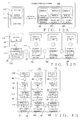
FIG. 1 is a block diagram illustrating a configuration example of a mixing console according to the present invention; -
FIG. 2 is a diagram illustrating an example of an operation panel provided on the mixing console according to one embodiment; -
FIG. 3 is a block diagram illustrating a configuration example for interlockingly controlling three operating regions and the channel selectors provided in each of the operating regions in the mixing console shown inFIG. 2 ; -
FIG. 4 is a block diagram illustrating an electrical hardware configuration example of the mixing console shown inFIG. 2 ; -
FIG. 5 is a block diagram illustrating a configuration of signal processing function of the mixing console shown inFIG. 2 ; -
FIGs. 6A through 6C are diagrams illustrating specific examples of interlocking settings of the channel selectors in the mixing console exemplified inFIG. 2 ,FIG. 6A illustrating an example in which each of the channel selectors in the three operating regions is independent of other channel selectors,FIG. 6B illustrating an example in which all of the channel selectors in the three operating regions are interlocked, andFIG. 6C illustrating an example in which the channel selectors of two adjacent operating regions are interlocked; -
FIG. 7 is a diagram illustrating an example of a detailed setting screen displayed on a display of the mixing console shown inFIG. 2 ; -
FIG. 8 is a block diagram illustrating a configuration example of another embodiment of the mixing console, in which the channel selectors are provided in a manual controls area and a display area of each of the operating regions; -
FIG. 9 is a diagram illustrating a specific example of an interlock setting of the channel selectors of the mixing console shown inFIG. 8 ; -
FIG. 10 is a diagram illustrating a configuration example of an operation panel in the mixing console according to still another embodiment; -
FIG. 11 is a block diagram illustrating a configuration example for interlockingly controlling the plurality of channel selectors in the mixing console shown inFIG. 10 ; -
FIGs. 12A and 12B are configuration examples of the mixing console according to a third embodiment;FIG. 12A is a block diagram illustrating a configuration example of a mixing console system configured by connecting the mixing console shown inFIG. 2 to a separately provided operating region unit;FIG. 12B is a block diagram illustrating a configuration example for interlockingly controlling the channel selectors on the mixing console side and the channel selectors on the separately provided operating region unit side in the mixing console system shown inFIG. 12A ; and -
FIG. 13 is a block diagram illustrating a configuration example of still another example of the mixing console provided with a plurality of manual controls areas and a plurality of display areas in each of the operating regions. -
FIG. 1 is a block diagram illustrating a configuration example of a mixing console (hereinafter referred to as a "mixer") according to the present invention. The mixer exemplified inFIG. 1 includes a plurality ofoperating regions 10a to 10f provided by dividing an operation panel into a plurality of regions, and a plurality of channels are allocated to each of the plurality ofoperating regions 10a to 10f. Each of theoperating regions 10a to 10f includeschannel selectors 20a to 20f, respectively. Each of the plurality ofchannel selectors 20a to 20f may select one of the plurality of channels allocated to theoperating regions 10a to 10f corresponding to thechannel selectors 20a to 20f, and may set a plurality of the values of parameters for signal processing on audio signals of the selected channel. Note that, in the description below, a "function for selecting a channel by a channel selector" is also referred to as an "SEL function." The one channel selected as an object of operation by the channel selector is also referred to as a "selected channel." Note that, in the present specification, when individually distinguishing a plurality of components from one another, such as when referring to theoperating regions 10a to 10f, for example, a reference numeral accompanied by an alphabet, such as "10a" and "10b" will be used. However, if the components do not need to be individually distinguished from one another, a reference numeral constituted only by a numerical number, such as "10," for example, will be used as a reference numeral. - The mixer includes an
interlocking controller 30 that interlocks thechannel selectors 20 between or among two or more operating regions 10. In the example shown inFIG. 1 , aninterlocking controller 30a is provided betweenoperating regions interlocking controller 30b is provided between 10b and 10c, aninterlocking controller 30c is provided between 10c and 10d, aninterlocking controller 30d is provided between 10c and 10e, and aninterlocking controller 30e is provided between 10e and 10f. Each of theinterlocking controllers 30a to 30e selects whether to interlock thechannel selectors 20 between the two operating regions 10, that is, switches between "interlock ON" and "interlock OFF" of the SEL function. In the case where the SEL function is set to interlock ON, if a certain channel is selected by one of thechannel selectors 20 of the two operating regions 10, this channel is also selected as the selected channel of theother channel selector 20. In the case where the SEL function is set to interlock OFF, eachchannel selector 20 can select a channel independently of other channel selectors. -
FIG. 2 is a diagram illustrating a configuration example of an operation panel of the mixer. The mixer shown inFIG. 2 is assumed to be a digital mixer in which signal processing on audio signals of a plurality of channels is performed by digital processing. In the example shown inFIG. 2 , the operation panel is divided into three operating regions, anoperating region 10L ("operating region L"), anoperating region 10C ("operating region C"), and anoperating region 10R ("operating region R"). Theoperating regions reference numerals FIG. 3 described later). Each of theoperating regions manual controls areas physical controls display areas display 12. InFIG. 2 , themanual controls areas 11 a to 11c and thedisplay areas 13a to 13c are respectively surrounded by dotted lines. Each of themanual controls areas display areas display areas display 12. - Each of the
manual controls areas 11a to 11c includes a plurality of physical controls such as afader 14 and abutton switch 15 provided for each of the plurality of channel strips (an operation section for each channel). For each channel strip, one of a plurality of channels allocated to one operating region 10 to which the channel strip belongs is allocated to the channel strip. A human operator can adjust a part of (major part of) the values of the parameters of signal processing on audio signals of the channel allocated to each channel strip using a fader and the like of that channel strip. - In addition, each of the
manual controls areas 11a to 11c has, in corresponding relation to the channel strip in each area, achannel selecting switch 16 for selecting the channel. The "channel selecting switch" is referred to as "SEL switch" hereinafter. When acertain SEL switch 16 is set to ON by operation of a human operator, a CPU (denoted byreference numeral 31 inFIG. 4 described later) selects the channel allocated to the channel strip corresponding to that SEL switch 16 as the selected channel in that manual controls area 11. - Further, each of the
manual controls areas 11a to 11c may include a sub-display 17 capable of displaying various information. Each of the sub-displays 17 is constituted by an LCD or an LED, and can display various information including information on the selected channel and the like, for example, based on instructions from the CPU (denoted byreference numeral 31 inFIG. 4 described later). - The
display 12 in each of thedisplay areas 13a to 13c may be constituted by a touch panel that allows an input by contact operation onto a screen of a display device such as an LCD or an LED, and can display various visual screens including a detailed setting screen and the like of the selected channel, for example, based on the instructions from the CPU (denoted byreference numeral 31 inFIG. 4 described later). - Also, each of the
display areas 13a to 13c may include one or morephysical controls 18 for implementing an operation relating to an image object displayed on thedisplay 12. Note that, in the example shown inFIG. 2 , while the configuration of a plurality of thephysical controls 18 included in thedisplay area 13c is different between those of thedisplay areas physical controls 18 in all of thedisplay areas -
FIG. 3 illustrates a configuration example for interlockingly controlling the three operating regions and the SEL function in each of the operating regions in the mixing console shown in the aforementionedFIG. 2 . In the configuration example shown inFIG. 3 , the interlockingcontroller 30 can make interlock ON/OFF setting between theSEL function 20L of theoperating region 10L and theSEL function 20C of theoperating region 10C as well as interlock ON/OFF setting between theSEL function 20C of theoperating region 10C and theSEL function 20R of theoperating region 10R. Note that a specific example of a combination of the interlock ON/Off setting will be described later. -
FIG. 4 is a block diagram illustrating an electrical hardware configuration example of the mixer shown inFIG. 2 . The mixer includes a central processing unit (CPU) 31, amemory 32, adisplay section 33, anoperation section 34, and asignal processing section 35. Thesignal processing section 35 may be referred to as "mixing section" hereinafter. TheCPU 31, thememory 32, thedisplay section 33, theoperation section 34, and themixing section 35 are connected via a communication bus 36so that various control signals can be communicated between theCPU 31 and each of thesections 32 to 35. In addition, analog audio signals or digital audio signals may be input to themixing section 35 from an input device such as a microphone and an audio reproduction device, and analog audio signals or digital audio signals may be output from the mixingsection 35 to an output device such as an amplifier and a loudspeaker. - The
CPU 31 controls an overall behavior of the mixer by executing various programs stored in thememory 32. Thememory 32 stores various programs to be executed by theCPU 31 and various data in a nonvolatile manner. Also, thememory 32 is used in a loading area and a working area of the program to be executed by theCPU 31. Thememory 32 may be constituted by appropriately combining various memory devices such as a read-only memory, a random access memory, a flash memory and a hard disk. - The
display section 33 is constituted by thedisplay 12, the sub-display 17, a related interface circuit and the like, and displays various information based on display control signals supplied by theCPU 31 in the form of various graphics, letter and/or character strings, and the like. Theoperation section 34 is constituted by the plurality of manual controls of the manual controls area 11, thephysical controls 18 of the display area 13, the related interface circuit, and the like. A human operator can operate various manual controls of theoperation section 34 to set or change various parameters. TheCPU 31 acquires a detection signal responsive to an operation of theoperation section 34 by the human operator to control the behavior of the mixer based on the detected signal. - The mixing
section 35 is constituted by, for example, a DSP (Digital Signal Processor) and a signal processing device virtually realized by theCPU 31 and the software stored in thememory 32. The mixingsection 35 executes a program for signal processing to process audio signals of one or more systems (or channels) supplied via an input device (not shown) and output the processed audio signals to an output device (not shown). The signal processing performed by the mixingsection 35 at least includes a mixing processing for mixing audio signals of at least a plurality of systems (or channels). This signal processing is controlled based on various parameter values stored in thememory 32. Thememory 32 stores therein a plurality of parameters used in signal processing of each channel corresponding to the plurality of channels provided in the mixer. -
FIG. 5 is a block diagram illustrating a configuration of signal processing function of the mixer. Behaviors of elements shown inFIG. 5 are realized by digital signal processing by the mixingsection 35. The mixer has a plurality ofinput channels 40a to 40n. Each of theinput channels 40a to 40n receives the audio signals from an input port (not shown) provided in corresponding relation to theinput channels 40a to 40n to perform signal processing based on the values of various parameters of theinput channels 40a to 40n. Then, the processed audio signals are output to mixingbuses 42a to 42m (signals may be output to all bus lines or selectively to some bus lines). Further, the mixer has a plurality of output channels 44a to 44m, and each of the output channels 44 is provided in corresponding relation to one of the bus lines of mixingbuses 42a to 42m. Each of the output channels 44a to 44m implements signal processing on the audio signals output from the corresponding bus lines based on the values of various parameters of each channel. Signal processing performed for theinput channels 40a to 40n and the output channels 44a to 44m is, for example, volume level adjustment, equalizing, panning, applying various effects, and the like based on the values of various parameters stored in thememory 32. - Next, an interlock setting of the SEL functions 20L, 20C and 20R provided in the
operating regions display 12, for example. The combination of two or more operating regions 10 for which the SEL function will be interlocked may be arbitrarily designated by a human operator. Instead, the human operator may have an opportunity to select one combination from a predetermined set of combination patterns. - Once the interlock setting of the SEL function performed by the human operator has been completed, the
CPU 31 stores interlocking control information that indicates the combination of the operating regions 10 for which the set SEL function should be interlocked. The interlocking control information is, for example, information that indicates an interlock ON/OFF setting state between or among two or more operating regions 10. When a particular channel is selected by operation of aparticular SEL switch 16, theCPU 31 selects, as a selected channel of one operating region 10 to which that the operatedSEL switch 16 belongs, a channel corresponding to the operatedSEL switch 16. At the same time, theCPU 31 specifies, based on the interlocking control information stored in thememory 32, all other operating regions 10 which are set to be interlocked (interlock ON) with the one operating region 10 to which the operatedSEL switch 16 belongs, and interlocks the SEL functions of all other operating regions 10 that have been specified. In other words, in the case where a selected channel for a particular operating region (for example, 10L) is changed by turning ON a particular SEL switch 16 in the operating region (10L), the same channel as the selected channel by the operatedSEL switch 16 will be selected too as a selected channel in the SEL functions of all other operating regions (e.g., 10C) that are set to be interlocked with the operating region (10L). Further, when a selected channel of a particular operating region (e.g., 10R) is changed by turning ON a particular SEL switch 16 in the operating region (10R), the selected channel will only be changed in that operating region (10R) if the SEL function of the operating region (10R) is not interlocked (interlock OFF) with any other operating region. The behavior of theCPU 31 based on the above-mentioned interlocking control information corresponds to the behavior of the interlockingcontroller 30. -
FIGs. 6A, 6B, 6C illustrate specific examples of combinations of theoperating regions SEL function 20 will be interlocked.FIG. 6A illustrates an example in which interlocking of the SEL function is set to OFF in all of theoperating regions respective operating regions FIG. 7 to be described later) for setting the parameters of the respective selected channels will be displayed on thedisplay 12 of theoperating regions CPU 31 based on the values of various parameters corresponding to the selected channel stored in thememory 32. The human operator, using thedisplay 12, thecontrols 18, and the like in thedisplay areas respective operating regions - If the mixer is used as shown in the aforementioned
FIG. 6A , three channels can be selected simultaneously on one mixer. Thus, the human operator can efficiently use the threeoperating regions operating regions operating regions controls display 12 and the like, in each of the operating regions 10 on the operation panel without requiring setting change operation such as switching of hierarchy. Accordingly, compared to the conventional digital mixer with which only one channel can be selected per mixer, operability in terms of adjustment of the detailed parameter values of the plurality of channels is improved. -
FIG. 6B illustrates an example in which the SEL functions 20L, 20C and 20R of all theoperating regions operating regions SEL function 20. In the case where the SEL functions 20 of two or more operating regions 10 are interlocked in this way, the CPU31 may display the detailed setting screen of the selected channel on at least one of thedisplays 12 of all the operating regions 10 to be interlocked. Instead, theCPU 31 may display the detailed setting screen of the selected channel on thedisplay 12 of all the operating regions 10 to be interlocked. -
FIG. 6C illustrates an example in which the SEL functions 20C, 20R of twoadjacent operating regions SEL function 20L of theoperating region 10L is independent of other SEL functions 20, as still another example of interlock setting of the SEL function. In this case, if one selected channel is selected on one of theoperating regions operating regions display 12 of at least one of theoperating regions operating region 10L independently of theother operating regions regions SEL function 20 and the oneoperating region 10L will have oneSEL function 20. Accordingly, the operation panel of one mixer may be divided into two parts each having theSEL function 20. Note that, in addition to the above example, theSEL function 20L and theSEL function 20R may be interlocked while theSEL function 20C may be made independent. -
FIG. 7 illustrates an example of a detailed setting screen displayed on thedisplay 12. InFIG. 7 , a channelname display area 51 provided on an upper side of adetailed setting screen 50 displays a channel name ("CH1 Vocal" in the figure) of the currently selected channel. A channelname display area 52 provided on a lower side of thescreen 50 displays a plurality of channel names side by side in a horizontal direction of the screen (e.g., "CH1 Vocal," "CH2 Guitar," "CH3 Bass," and "CH4 Keyboard" as shown in the figure), and the channel name of the currently selected channel ("CH1 Vocal" as shown in the figure) is displayed in a different manner from those of other channel names, for example, by hatching the channel name. TheCPU 31 specifies the selected channel according to each operating region 10, and controls display of the channelname display areas memory 32. Also, thedetailed setting screen 50displays images CPU 31 executes control so as to display the values of applicable parameters on theimages memory 32. The human operator may select, for example, theimages images manual control 18 corresponding to thedisplay 12 that has the applicable image displayed thereon. TheCPU 31, in accordance with the operation of the physicalmanual control 18, changes the value of the parameter corresponding to the operation which is stored in thememory 32. Note that thedetailed setting screen 50 of the selected channel may be displayed on the sub-display 17. - Further, the channel
name display area name display area detailed setting screen 50. To be specific, as shown inFIG. 7 , images of right and left arrows are displayed on right and left ends of the channelname display area 51, and a channel will be selected by the human operator touching one of the arrow images. Instead, the channel may be selected by the human operator touching one of a plurality of channel names displayed on the channelname display area 52. When the selected channel is changed on one of the channelname display areas CPU 31 changes the selected channel to be displayed on the other of the channelname display areas screen 50. In addition, the selection of a channel by the channelname display area SEL function 20 of the applicable operating region 10. -
FIG. 8 is a configuration example of the second embodiment of the mixing console, in which corresponding one of themanual controls areas 11a to 11c (i.e., the first operating section) and corresponding one of thedisplay areas 13a to 13c (i.e., the second operating section) included in each of theoperating regions manual controls areas SEL switch 16 in each of the manual controls areas 11 as the first channel selector. Also, the selected channels for the SEL functions 20a, 20d, 20f of thedisplay areas 13a to 13c can be selected by using SEL switch images (channelname display areas 51, 52) in thedetailed setting screen 50 displayed on thedisplay 12 as the second channel selector. - Also in the mixer configuration example shown in
FIG. 8 , the interlockingcontroller 30 can be interlocked with two or more SEL functions 20a to 20f in an arbitrary combination. In the example shown inFIG. 8 , the interlockingcontroller 30 can set theSEL function 20 to interlock ON/OFF between themanual controls area 11a and thedisplay area 13a of theoperating region 10L, between themanual controls area 11b and thedisplay area 13b of theoperating region 10C, between themanual controls area 11c and thedisplay area 13c of theoperating region 10R, between themanual controls area 11a of theoperating region 10L and the manual controlsarea 11b of theoperating region 10C, and between themanual controls area 11b of theoperating region 10C and themanual controls area 11c of theoperating region 10R. Namely, the interlockingcontroller 30 is configured to interlock the first andsecond channel selectors 20a to 20f between or among desired one ormore operating regions -
FIG. 9 is an example of an interlock setting of each of the SEL functions 20a to 20f shown in the aforementionedFIG. 8 , in which the SEL functions 20b, 20c, 20e and 20f of all themanual controls areas 11 a to 11c and onedisplay area 13 c, respectively, are set to interlock ON, while therespective SEL functions display area 13a of theoperating region 10L and thedisplay area 13b of theoperating region 10C are made independently. In this case, when a certain channel is selected in themanual controls areas display area 13c, the selected channel will become the selected channel of the SEL function for all of themanual controls areas display area 13c. However, the channel for the SEL function can be selected independently at thedisplay areas - Note that, as exemplified in
FIGs. 8 and 9 , in a configuration in which each of themanual controls areas 11a to 11c and thedisplay areas 13a to 13c has theSEL function 20, respectively, the detailed setting screen of the selected channel can be displayed on the sub-displays 17 of themanual controls areas 11a to 11c in the case where the SEL functions of each of themanual controls areas 11a to 11c are to be used independently, or in the case where the SEL functions of two or moremanual controls areas 11 a to 11c are to be interlocked. By configuring themanual controls areas 11a to 11c and thedisplay areas 13a to 13c as thus, the operating regions 10 can be used in flexible combinations. -
FIG. 10 is a diagram illustrating a configuration example of an operation panel in the mixer according to another embodiment. Components shown inFIG. 10 that have already been described with reference toFIG. 2 are denoted by the same reference numerals as inFIG. 2 , and reference thereto will be omitted, as appropriate. In the configuration example of the operation panel illustrated inFIG. 10 , a selectedchannel area 60 constituted by a plurality of physical controls for adjusting the values of the parameters of the selected channel is provided in theoperating region 10R in place of thedisplay area 13c (refer toFIG. 2 , and the like). In addition, anexternal display 61 is connected to the mixer. Theexternal display 61 is capable of displaying thedetailed setting screen 50 shown in the aforementionedFIG. 7 , for example, and the channelname display areas detailed setting screen 50 function as the SEL switch images. Operation on theexternal display 61 can be made, for example, via a touch panel. - The mixer illustrated in
FIG. 10 is assumed to be configured by having, as an example, oneSEL function 20 in theoperating region 10R, oneindependent SEL function 20 in each of thedisplay areas operating regions SEL function 20 in theexternal display 61. Note that, for the convenience of description, these four SEL functions 20 may also be referred to as a "SEL master." In this case, as shown inFIG. 11 , the interlockingcontroller 30 can set the SEL function to interlock ON/OFF between themanual controls area 11a of theoperating region 10L and thedisplay area 13a of theoperating region 10L, between themanual controls area 11a of theoperating region 10L andmanual controls 11b of theoperating region 10C, between themanual controls area 11b of theoperating region 10C and thedisplay area 13b of theoperating region 10C, between themanual controls area 11b of theoperating region 10C and theoperating region 10R, and between theoperating region 10R and theexternal display 61. - The operation panel shown in
FIG. 10 may be, as an example, configured such that themanual controls area 11a of theoperating region operating region 10C do not have independent SEL functions, and that the SEL functions (SEL slave) using theseareas areas SEL switch 16 of theareas manual controls areas areas - In still another embodiment, an external operating region unit can be connected to the mixer.
FIGs. 12A and 12B illustrate a configuration example of a mixer system in which an externaloperating region unit 110 is connected to amixer 100 via a physical connection. Themixer 100 is configured similarly to the mixer shown inFIG. 8 , and includes threeoperating regions operating region unit 110 is a separate device from themixer 100, and includes a manual controlsarea 111 and adisplay area 113. The manual controlsarea 111 and thedisplay area 113 include, respectively, a plurality of manual controls for each channel strip, a display, and a group of the physical controls relating to the display. Further, the manual controlsarea 111 and thedisplay area 113 each has anindependent SEL function 20. In such a mixer system, the interlockingcontroller 30 can, as shown inFIG. 12B , set the SEL function to interlock ON/OFF between themanual controls area 111 of theoperating region unit 110 and themanual controls area 11a of theoperating region 10L of themixer 100. Accordingly, the SEL function of theoperating regions mixer 100 can be interlocked with the SEL function of the externaloperating region unit 110. Also, the SEL function between themanual controls area 111 and thedisplay area 113 may also be set to interlock ON/OFF within oneoperating region unit 110. Thus, even in the case where the number of the plurality of operating regions 10 are freely increased by connecting the externaloperating region unit 110 to themixer 100, the SEL function can be interlocked, including the externaloperating region unit 110. - Further, in the aforementioned embodiment, each of the operating regions 10 may include one or more manual controls area 11 and one or more display area 13. For example, in the configuration example shown in
FIG. 13 , theoperating region 10L includes twomanual controls areas display areas operating region 10C includes twomanual controls areas display areas operating region 10R includes twomanual controls areas display areas FIG. 13 , the interlockingcontroller 30 can set the SEL function to interlock ON/OFF between two adjacent areas of each of theoperating regions manual controls areas operating region 10L, between themanual controls area 11d and thedisplay area 13a, and between thedisplay areas controller 30 can set the SEL function to interlock ON/OFF between themanual controls area 11 a of theoperating region 10L and the manual controlsarea 11b of theoperating region 10C, and between themanual controls area 11b of theoperating region 10C and themanual controls area 11c of theoperating region 10R. - While the embodiments of the present invention have been described as above, the present invention is not limited to the above-described embodiments, and various modifications are possible without departing from the scope and spirit of the invention as described in the claims, specification, and the drawings. For example, the operating region 10 may be configured to include only one of the manual controls area 11, the display area 13, and the selected
channel area 60. Also, the configuration of the manual controls area 11 and the display area 13 is not limited to one including a fader manipulator according to each channel strip, a switch, an SEL switch, a display, and controls for operating the display as described above, and may be configured by including other components. InFIGs. 1, 3 ,8 ,11 ,12B and 13 , the interlockingcontroller 30 was described as being configured to set theSEL function 20 to interlock ON/OFF between two adjacently disposed components on the operation panel (two operating regions 10 or two manual controls areas 11). However, the interlocking control implemented by the interlockingcontroller 30 is not limited thereto, and any kind of control is possible as long as theSEL function 20 of two or more arbitrary components are interlocked. Further, the mixer may also be configured by software that realizes mixing processing on audio signals of a plurality of channels in a computer device such as a personal computer and a slate device. In that case, the operation panel screen displayed on the display of a computer device corresponds to the aforementioned operation panel.
Claims (4)
- A mixing console for controlling signal processing on audio signals of a plurality of channels, said mixing console comprising:a plurality of operating regions (10) provided by dividing an operation panel of the mixing console into a plurality of regions, a plurality of channels being allocated to each of the plurality of operating regions; anda plurality of channel selectors (20) provided in corresponding relation to the plurality of operating regions, each of the plurality of channel selectors configured to select one of the plurality of channels allocated to the operating region corresponding to the channel selector,wherein the operating region corresponding to the channel selector is configured to set a plurality of parameters for signal processing on an audio signal of the one channel selected by the channel selector.
- The mixing console as claimed in claim 1, further comprising an interlocking controller (30) configured to interlock the channel selectors between or among two or more operating regions.
- The mixing console as claimed in claim 1, wherein
each of the plurality of operating regions (10) includes a first operating section (11a - 11c) comprising a plurality of physical controls (14, 15) and a second operating section (13a - 13c) comprising at least a display (12), and
the channel selector (20) corresponding to each of the plurality of operating regions comprises first and second channel selectors (20b, 20c, 20e; 20a, 20d, 20f) provided in corresponding relation to the first and second operating sections (11a - 11c; 13a - 13c) included in the corresponding operating region. - The mixing console as claimed in claim 3, further comprising an interlocking controller (30) configured to interlock the first and second channel selectors (20b, 20c, 20e; 20a, 20d, 20f) between or among two or more of the first and second operating sections (11a - 11c, 13a-13c) of one or more operating regions (10).
Applications Claiming Priority (1)
| Application Number | Priority Date | Filing Date | Title |
|---|---|---|---|
| JP2014232225A JP6515496B2 (en) | 2014-11-14 | 2014-11-14 | Mixing console |
Publications (2)
| Publication Number | Publication Date |
|---|---|
| EP3021325A1 true EP3021325A1 (en) | 2016-05-18 |
| EP3021325B1 EP3021325B1 (en) | 2021-05-05 |
Family
ID=54608301
Family Applications (1)
| Application Number | Title | Priority Date | Filing Date |
|---|---|---|---|
| EP15194449.3A Active EP3021325B1 (en) | 2014-11-14 | 2015-11-13 | Mixing console |
Country Status (3)
| Country | Link |
|---|---|
| US (1) | US9929821B2 (en) |
| EP (1) | EP3021325B1 (en) |
| JP (1) | JP6515496B2 (en) |
Families Citing this family (4)
| Publication number | Priority date | Publication date | Assignee | Title |
|---|---|---|---|---|
| JP6926468B2 (en) * | 2016-12-22 | 2021-08-25 | ヤマハ株式会社 | Sound processing equipment and method |
| JP7400341B2 (en) | 2019-10-24 | 2023-12-19 | ティアック株式会社 | mixing console |
| JP7456212B2 (en) | 2020-03-13 | 2024-03-27 | ヤマハ株式会社 | Operation panel for sound processing device and method of operating the operation panel for sound processing device |
| US11625220B2 (en) * | 2020-11-11 | 2023-04-11 | Teac Corporation | Digital mixer having plurality of displays |
Citations (5)
| Publication number | Priority date | Publication date | Assignee | Title |
|---|---|---|---|---|
| US20020037085A1 (en) * | 2000-09-25 | 2002-03-28 | Hideyuki Ono | Data signal processing apparatus |
| US20050055117A1 (en) * | 2003-09-09 | 2005-03-10 | Yamaha Corporation | Digital mixer |
| JP2011109554A (en) | 2009-11-20 | 2011-06-02 | Yamaha Corp | Mixing console and program |
| US8050426B2 (en) * | 2004-07-13 | 2011-11-01 | Yamaha Corporation | Digital mixer apparatus and editing method therefor |
| JP2011234283A (en) * | 2010-04-30 | 2011-11-17 | Yamaha Corp | Mixing console |
Family Cites Families (4)
| Publication number | Priority date | Publication date | Assignee | Title |
|---|---|---|---|---|
| JP4210952B2 (en) * | 2005-03-31 | 2009-01-21 | ヤマハ株式会社 | Digital mixer |
| JP4449865B2 (en) * | 2005-09-05 | 2010-04-14 | ヤマハ株式会社 | Digital audio mixer |
| JP4380746B2 (en) * | 2007-07-23 | 2009-12-09 | ヤマハ株式会社 | Digital mixer |
| US8351623B2 (en) * | 2009-03-27 | 2013-01-08 | Yamaha Corporation | Audio mixing apparatus |
-
2014
- 2014-11-14 JP JP2014232225A patent/JP6515496B2/en active Active
-
2015
- 2015-11-13 US US14/941,441 patent/US9929821B2/en active Active
- 2015-11-13 EP EP15194449.3A patent/EP3021325B1/en active Active
Patent Citations (5)
| Publication number | Priority date | Publication date | Assignee | Title |
|---|---|---|---|---|
| US20020037085A1 (en) * | 2000-09-25 | 2002-03-28 | Hideyuki Ono | Data signal processing apparatus |
| US20050055117A1 (en) * | 2003-09-09 | 2005-03-10 | Yamaha Corporation | Digital mixer |
| US8050426B2 (en) * | 2004-07-13 | 2011-11-01 | Yamaha Corporation | Digital mixer apparatus and editing method therefor |
| JP2011109554A (en) | 2009-11-20 | 2011-06-02 | Yamaha Corp | Mixing console and program |
| JP2011234283A (en) * | 2010-04-30 | 2011-11-17 | Yamaha Corp | Mixing console |
Non-Patent Citations (4)
| Title |
|---|
| ' S YAMAHA: "YAMAHA DIGITAL MIXING CONSOLE CL5 CL3 CL1 Owner's Manual", 31 December 2013 (2013-12-31), JAPAN, XP055263984, Retrieved from the Internet <URL:http://download.yamaha.com/api/asset/file?language=en&site=countrysite-master.prod.wsys.yamaha.com&asset_id=59026> [retrieved on 20160408] * |
| YAMAHA, YAMAHA PM1D VERSION DIGITAL MIXING CONSOLE, Retrieved from the Internet <URL:http://proaudio.yamaha.cojp/downloads/brochures/mixers/pmldv2 brochure ja.pdf> |
| YAMAHA: "PM1D VERSION 2 DIGITAL AUDIO MIXING SYSTEM", 16 May 2011 (2011-05-16), Japan, XP055263978, Retrieved from the Internet <URL:http://download.yamaha.com/search/product/?language=en&site=uk.yamaha.com&category_id=16507&product_id=437395> [retrieved on 20160408] * |
| YAMAHA: "YAMAHA DIGITAL MIXING CONSOLE CL5/CL3/CL I /Owner's Manual", 2012 |
Also Published As
| Publication number | Publication date |
|---|---|
| US20160142165A1 (en) | 2016-05-19 |
| JP2016096484A (en) | 2016-05-26 |
| JP6515496B2 (en) | 2019-05-22 |
| EP3021325B1 (en) | 2021-05-05 |
| US9929821B2 (en) | 2018-03-27 |
Similar Documents
| Publication | Publication Date | Title |
|---|---|---|
| JP5454405B2 (en) | Acoustic adjustment console | |
| US8098850B2 (en) | Digital mixer | |
| JP6904012B2 (en) | Sound signal processing device control method, sound signal processing device and program | |
| JP5246110B2 (en) | Digital mixer | |
| EP3021325B1 (en) | Mixing console | |
| JP6693569B2 (en) | Mixer, control method of mixer, and program | |
| JP6946811B2 (en) | Sound processing device and parameter assignment method | |
| JP6488811B2 (en) | Audio signal processing device | |
| JP2007074110A (en) | Digital audio mixer | |
| JP5789961B2 (en) | Digital audio mixer | |
| US10198169B2 (en) | Parameter controller, storage medium and parameter controlling method | |
| CN108509120B (en) | Signal control device and method for deploying parameters | |
| US10970032B2 (en) | Sound processing apparatus and method | |
| US20160283186A1 (en) | Audio signal processing apparatus capable of signal processing for previewing purpose | |
| JP5489001B2 (en) | Acoustic signal processing device | |
| JP4930112B2 (en) | Mixing equipment | |
| JP4609234B2 (en) | Digital mixer | |
| JP2011109554A (en) | Mixing console and program | |
| US8340324B2 (en) | Device for setting parameters of mixer | |
| JP4458006B2 (en) | Digital mixer | |
| CN110992918A (en) | Audio signal processing device, audio signal processing method, and storage medium | |
| JP2018142931A (en) | Sound control system and method | |
| JP2020123803A (en) | Sound signal processing device, sound signal processing method and program | |
| JP2009094835A (en) | Audio device with touch panel | |
| JP2006270667A (en) | Input output setting device and program for mixer |
Legal Events
| Date | Code | Title | Description |
|---|---|---|---|
| PUAI | Public reference made under article 153(3) epc to a published international application that has entered the european phase |
Free format text: ORIGINAL CODE: 0009012 |
|
| AK | Designated contracting states |
Kind code of ref document: A1 Designated state(s): AL AT BE BG CH CY CZ DE DK EE ES FI FR GB GR HR HU IE IS IT LI LT LU LV MC MK MT NL NO PL PT RO RS SE SI SK SM TR |
|
| AX | Request for extension of the european patent |
Extension state: BA ME |
|
| RIN1 | Information on inventor provided before grant (corrected) |
Inventor name: FUJITA, HIROAKI Inventor name: NISHIKORI, TAKU Inventor name: TAYLOR, CHRIS Inventor name: TANAKA, TAKUMI Inventor name: ANGELL, CHRIS |
|
| STAA | Information on the status of an ep patent application or granted ep patent |
Free format text: STATUS: REQUEST FOR EXAMINATION WAS MADE |
|
| 17P | Request for examination filed |
Effective date: 20161110 |
|
| RBV | Designated contracting states (corrected) |
Designated state(s): AL AT BE BG CH CY CZ DE DK EE ES FI FR GB GR HR HU IE IS IT LI LT LU LV MC MK MT NL NO PL PT RO RS SE SI SK SM TR |
|
| STAA | Information on the status of an ep patent application or granted ep patent |
Free format text: STATUS: EXAMINATION IS IN PROGRESS |
|
| 17Q | First examination report despatched |
Effective date: 20200117 |
|
| GRAP | Despatch of communication of intention to grant a patent |
Free format text: ORIGINAL CODE: EPIDOSNIGR1 |
|
| STAA | Information on the status of an ep patent application or granted ep patent |
Free format text: STATUS: GRANT OF PATENT IS INTENDED |
|
| INTG | Intention to grant announced |
Effective date: 20201202 |
|
| GRAS | Grant fee paid |
Free format text: ORIGINAL CODE: EPIDOSNIGR3 |
|
| GRAA | (expected) grant |
Free format text: ORIGINAL CODE: 0009210 |
|
| STAA | Information on the status of an ep patent application or granted ep patent |
Free format text: STATUS: THE PATENT HAS BEEN GRANTED |
|
| AK | Designated contracting states |
Kind code of ref document: B1 Designated state(s): AL AT BE BG CH CY CZ DE DK EE ES FI FR GB GR HR HU IE IS IT LI LT LU LV MC MK MT NL NO PL PT RO RS SE SI SK SM TR |
|
| REG | Reference to a national code |
Ref country code: GB Ref legal event code: FG4D |
|
| REG | Reference to a national code |
Ref country code: CH Ref legal event code: EP |
|
| REG | Reference to a national code |
Ref country code: AT Ref legal event code: REF Ref document number: 1390828 Country of ref document: AT Kind code of ref document: T Effective date: 20210515 |
|
| REG | Reference to a national code |
Ref country code: DE Ref legal event code: R096 Ref document number: 602015068890 Country of ref document: DE |
|
| REG | Reference to a national code |
Ref country code: IE Ref legal event code: FG4D |
|
| REG | Reference to a national code |
Ref country code: LT Ref legal event code: MG9D |
|
| REG | Reference to a national code |
Ref country code: AT Ref legal event code: MK05 Ref document number: 1390828 Country of ref document: AT Kind code of ref document: T Effective date: 20210505 |
|
| PG25 | Lapsed in a contracting state [announced via postgrant information from national office to epo] |
Ref country code: LT Free format text: LAPSE BECAUSE OF FAILURE TO SUBMIT A TRANSLATION OF THE DESCRIPTION OR TO PAY THE FEE WITHIN THE PRESCRIBED TIME-LIMIT Effective date: 20210505 Ref country code: FI Free format text: LAPSE BECAUSE OF FAILURE TO SUBMIT A TRANSLATION OF THE DESCRIPTION OR TO PAY THE FEE WITHIN THE PRESCRIBED TIME-LIMIT Effective date: 20210505 Ref country code: BG Free format text: LAPSE BECAUSE OF FAILURE TO SUBMIT A TRANSLATION OF THE DESCRIPTION OR TO PAY THE FEE WITHIN THE PRESCRIBED TIME-LIMIT Effective date: 20210805 Ref country code: AT Free format text: LAPSE BECAUSE OF FAILURE TO SUBMIT A TRANSLATION OF THE DESCRIPTION OR TO PAY THE FEE WITHIN THE PRESCRIBED TIME-LIMIT Effective date: 20210505 Ref country code: HR Free format text: LAPSE BECAUSE OF FAILURE TO SUBMIT A TRANSLATION OF THE DESCRIPTION OR TO PAY THE FEE WITHIN THE PRESCRIBED TIME-LIMIT Effective date: 20210505 |
|
| PG25 | Lapsed in a contracting state [announced via postgrant information from national office to epo] |
Ref country code: IS Free format text: LAPSE BECAUSE OF FAILURE TO SUBMIT A TRANSLATION OF THE DESCRIPTION OR TO PAY THE FEE WITHIN THE PRESCRIBED TIME-LIMIT Effective date: 20210905 Ref country code: GR Free format text: LAPSE BECAUSE OF FAILURE TO SUBMIT A TRANSLATION OF THE DESCRIPTION OR TO PAY THE FEE WITHIN THE PRESCRIBED TIME-LIMIT Effective date: 20210806 Ref country code: LV Free format text: LAPSE BECAUSE OF FAILURE TO SUBMIT A TRANSLATION OF THE DESCRIPTION OR TO PAY THE FEE WITHIN THE PRESCRIBED TIME-LIMIT Effective date: 20210505 Ref country code: RS Free format text: LAPSE BECAUSE OF FAILURE TO SUBMIT A TRANSLATION OF THE DESCRIPTION OR TO PAY THE FEE WITHIN THE PRESCRIBED TIME-LIMIT Effective date: 20210505 Ref country code: SE Free format text: LAPSE BECAUSE OF FAILURE TO SUBMIT A TRANSLATION OF THE DESCRIPTION OR TO PAY THE FEE WITHIN THE PRESCRIBED TIME-LIMIT Effective date: 20210505 Ref country code: NO Free format text: LAPSE BECAUSE OF FAILURE TO SUBMIT A TRANSLATION OF THE DESCRIPTION OR TO PAY THE FEE WITHIN THE PRESCRIBED TIME-LIMIT Effective date: 20210805 Ref country code: PT Free format text: LAPSE BECAUSE OF FAILURE TO SUBMIT A TRANSLATION OF THE DESCRIPTION OR TO PAY THE FEE WITHIN THE PRESCRIBED TIME-LIMIT Effective date: 20210906 Ref country code: PL Free format text: LAPSE BECAUSE OF FAILURE TO SUBMIT A TRANSLATION OF THE DESCRIPTION OR TO PAY THE FEE WITHIN THE PRESCRIBED TIME-LIMIT Effective date: 20210505 Ref country code: ES Free format text: LAPSE BECAUSE OF FAILURE TO SUBMIT A TRANSLATION OF THE DESCRIPTION OR TO PAY THE FEE WITHIN THE PRESCRIBED TIME-LIMIT Effective date: 20210505 |
|
| REG | Reference to a national code |
Ref country code: NL Ref legal event code: MP Effective date: 20210505 |
|
| PG25 | Lapsed in a contracting state [announced via postgrant information from national office to epo] |
Ref country code: NL Free format text: LAPSE BECAUSE OF FAILURE TO SUBMIT A TRANSLATION OF THE DESCRIPTION OR TO PAY THE FEE WITHIN THE PRESCRIBED TIME-LIMIT Effective date: 20210505 |
|
| PG25 | Lapsed in a contracting state [announced via postgrant information from national office to epo] |
Ref country code: RO Free format text: LAPSE BECAUSE OF FAILURE TO SUBMIT A TRANSLATION OF THE DESCRIPTION OR TO PAY THE FEE WITHIN THE PRESCRIBED TIME-LIMIT Effective date: 20210505 Ref country code: SM Free format text: LAPSE BECAUSE OF FAILURE TO SUBMIT A TRANSLATION OF THE DESCRIPTION OR TO PAY THE FEE WITHIN THE PRESCRIBED TIME-LIMIT Effective date: 20210505 Ref country code: SK Free format text: LAPSE BECAUSE OF FAILURE TO SUBMIT A TRANSLATION OF THE DESCRIPTION OR TO PAY THE FEE WITHIN THE PRESCRIBED TIME-LIMIT Effective date: 20210505 Ref country code: DK Free format text: LAPSE BECAUSE OF FAILURE TO SUBMIT A TRANSLATION OF THE DESCRIPTION OR TO PAY THE FEE WITHIN THE PRESCRIBED TIME-LIMIT Effective date: 20210505 Ref country code: EE Free format text: LAPSE BECAUSE OF FAILURE TO SUBMIT A TRANSLATION OF THE DESCRIPTION OR TO PAY THE FEE WITHIN THE PRESCRIBED TIME-LIMIT Effective date: 20210505 Ref country code: CZ Free format text: LAPSE BECAUSE OF FAILURE TO SUBMIT A TRANSLATION OF THE DESCRIPTION OR TO PAY THE FEE WITHIN THE PRESCRIBED TIME-LIMIT Effective date: 20210505 |
|
| REG | Reference to a national code |
Ref country code: DE Ref legal event code: R097 Ref document number: 602015068890 Country of ref document: DE |
|
| PLBE | No opposition filed within time limit |
Free format text: ORIGINAL CODE: 0009261 |
|
| STAA | Information on the status of an ep patent application or granted ep patent |
Free format text: STATUS: NO OPPOSITION FILED WITHIN TIME LIMIT |
|
| 26N | No opposition filed |
Effective date: 20220208 |
|
| PG25 | Lapsed in a contracting state [announced via postgrant information from national office to epo] |
Ref country code: IS Free format text: LAPSE BECAUSE OF FAILURE TO SUBMIT A TRANSLATION OF THE DESCRIPTION OR TO PAY THE FEE WITHIN THE PRESCRIBED TIME-LIMIT Effective date: 20210905 Ref country code: AL Free format text: LAPSE BECAUSE OF FAILURE TO SUBMIT A TRANSLATION OF THE DESCRIPTION OR TO PAY THE FEE WITHIN THE PRESCRIBED TIME-LIMIT Effective date: 20210505 |
|
| PG25 | Lapsed in a contracting state [announced via postgrant information from national office to epo] |
Ref country code: MC Free format text: LAPSE BECAUSE OF FAILURE TO SUBMIT A TRANSLATION OF THE DESCRIPTION OR TO PAY THE FEE WITHIN THE PRESCRIBED TIME-LIMIT Effective date: 20210505 |
|
| REG | Reference to a national code |
Ref country code: CH Ref legal event code: PL |
|
| GBPC | Gb: european patent ceased through non-payment of renewal fee |
Effective date: 20211113 |
|
| PG25 | Lapsed in a contracting state [announced via postgrant information from national office to epo] |
Ref country code: LU Free format text: LAPSE BECAUSE OF NON-PAYMENT OF DUE FEES Effective date: 20211113 Ref country code: IT Free format text: LAPSE BECAUSE OF FAILURE TO SUBMIT A TRANSLATION OF THE DESCRIPTION OR TO PAY THE FEE WITHIN THE PRESCRIBED TIME-LIMIT Effective date: 20210505 Ref country code: BE Free format text: LAPSE BECAUSE OF NON-PAYMENT OF DUE FEES Effective date: 20211130 |
|
| REG | Reference to a national code |
Ref country code: BE Ref legal event code: MM Effective date: 20211130 |
|
| PG25 | Lapsed in a contracting state [announced via postgrant information from national office to epo] |
Ref country code: LI Free format text: LAPSE BECAUSE OF NON-PAYMENT OF DUE FEES Effective date: 20211130 Ref country code: CH Free format text: LAPSE BECAUSE OF NON-PAYMENT OF DUE FEES Effective date: 20211130 |
|
| PG25 | Lapsed in a contracting state [announced via postgrant information from national office to epo] |
Ref country code: IE Free format text: LAPSE BECAUSE OF NON-PAYMENT OF DUE FEES Effective date: 20211113 Ref country code: GB Free format text: LAPSE BECAUSE OF NON-PAYMENT OF DUE FEES Effective date: 20211113 |
|
| PG25 | Lapsed in a contracting state [announced via postgrant information from national office to epo] |
Ref country code: FR Free format text: LAPSE BECAUSE OF NON-PAYMENT OF DUE FEES Effective date: 20211130 |
|
| PG25 | Lapsed in a contracting state [announced via postgrant information from national office to epo] |
Ref country code: HU Free format text: LAPSE BECAUSE OF FAILURE TO SUBMIT A TRANSLATION OF THE DESCRIPTION OR TO PAY THE FEE WITHIN THE PRESCRIBED TIME-LIMIT; INVALID AB INITIO Effective date: 20151113 |
|
| PG25 | Lapsed in a contracting state [announced via postgrant information from national office to epo] |
Ref country code: CY Free format text: LAPSE BECAUSE OF FAILURE TO SUBMIT A TRANSLATION OF THE DESCRIPTION OR TO PAY THE FEE WITHIN THE PRESCRIBED TIME-LIMIT Effective date: 20210505 |
|
| PG25 | Lapsed in a contracting state [announced via postgrant information from national office to epo] |
Ref country code: MK Free format text: LAPSE BECAUSE OF FAILURE TO SUBMIT A TRANSLATION OF THE DESCRIPTION OR TO PAY THE FEE WITHIN THE PRESCRIBED TIME-LIMIT Effective date: 20210505 |
|
| PG25 | Lapsed in a contracting state [announced via postgrant information from national office to epo] |
Ref country code: MT Free format text: LAPSE BECAUSE OF FAILURE TO SUBMIT A TRANSLATION OF THE DESCRIPTION OR TO PAY THE FEE WITHIN THE PRESCRIBED TIME-LIMIT Effective date: 20210505 |
|
| PG25 | Lapsed in a contracting state [announced via postgrant information from national office to epo] |
Ref country code: TR Free format text: LAPSE BECAUSE OF FAILURE TO SUBMIT A TRANSLATION OF THE DESCRIPTION OR TO PAY THE FEE WITHIN THE PRESCRIBED TIME-LIMIT Effective date: 20210505 |
|
| PGFP | Annual fee paid to national office [announced via postgrant information from national office to epo] |
Ref country code: DE Payment date: 20251119 Year of fee payment: 11 |