EP3021096A1 - Colorimeter calibration - Google Patents
Colorimeter calibration Download PDFInfo
- Publication number
- EP3021096A1 EP3021096A1 EP14003792.0A EP14003792A EP3021096A1 EP 3021096 A1 EP3021096 A1 EP 3021096A1 EP 14003792 A EP14003792 A EP 14003792A EP 3021096 A1 EP3021096 A1 EP 3021096A1
- Authority
- EP
- European Patent Office
- Prior art keywords
- chromaticity
- calibration
- optimized
- achromatic
- values
- Prior art date
- Legal status (The legal status is an assumption and is not a legal conclusion. Google has not performed a legal analysis and makes no representation as to the accuracy of the status listed.)
- Granted
Links
- 238000005259 measurement Methods 0.000 claims abstract description 30
- 238000000034 method Methods 0.000 claims description 64
- 238000013507 mapping Methods 0.000 claims description 44
- 238000009826 distribution Methods 0.000 claims description 32
- 230000003595 spectral effect Effects 0.000 claims description 29
- 230000004044 response Effects 0.000 claims description 20
- 230000035945 sensitivity Effects 0.000 claims description 19
- 238000012545 processing Methods 0.000 claims description 18
- 238000001914 filtration Methods 0.000 claims description 9
- 238000003860 storage Methods 0.000 claims description 9
- 230000000694 effects Effects 0.000 description 53
- 239000011159 matrix material Substances 0.000 description 37
- 235000019557 luminance Nutrition 0.000 description 25
- VYZAMTAEIAYCRO-UHFFFAOYSA-N Chromium Chemical compound [Cr] VYZAMTAEIAYCRO-UHFFFAOYSA-N 0.000 description 22
- 238000003384 imaging method Methods 0.000 description 22
- 230000006870 function Effects 0.000 description 21
- 238000010586 diagram Methods 0.000 description 16
- 238000001228 spectrum Methods 0.000 description 15
- 238000005286 illumination Methods 0.000 description 8
- 238000004422 calculation algorithm Methods 0.000 description 7
- 230000009466 transformation Effects 0.000 description 7
- 238000009795 derivation Methods 0.000 description 6
- 238000005457 optimization Methods 0.000 description 4
- 230000003213 activating effect Effects 0.000 description 3
- 238000003491 array Methods 0.000 description 3
- 230000000295 complement effect Effects 0.000 description 3
- 230000007812 deficiency Effects 0.000 description 3
- 238000012360 testing method Methods 0.000 description 3
- WFKWXMTUELFFGS-UHFFFAOYSA-N tungsten Chemical compound [W] WFKWXMTUELFFGS-UHFFFAOYSA-N 0.000 description 3
- 229910052721 tungsten Inorganic materials 0.000 description 3
- 239000010937 tungsten Substances 0.000 description 3
- 230000006399 behavior Effects 0.000 description 2
- 230000005540 biological transmission Effects 0.000 description 2
- 238000006243 chemical reaction Methods 0.000 description 2
- 238000005094 computer simulation Methods 0.000 description 2
- 238000005516 engineering process Methods 0.000 description 2
- 230000014509 gene expression Effects 0.000 description 2
- 238000004519 manufacturing process Methods 0.000 description 2
- 238000012067 mathematical method Methods 0.000 description 2
- 230000003278 mimic effect Effects 0.000 description 2
- 238000013488 ordinary least square regression Methods 0.000 description 2
- 239000004065 semiconductor Substances 0.000 description 2
- 238000000844 transformation Methods 0.000 description 2
- 239000006096 absorbing agent Substances 0.000 description 1
- 238000013459 approach Methods 0.000 description 1
- 229910052729 chemical element Inorganic materials 0.000 description 1
- 230000004456 color vision Effects 0.000 description 1
- 239000003086 colorant Substances 0.000 description 1
- 238000004737 colorimetric analysis Methods 0.000 description 1
- 230000001447 compensatory effect Effects 0.000 description 1
- 230000008094 contradictory effect Effects 0.000 description 1
- 238000012937 correction Methods 0.000 description 1
- 230000002950 deficient Effects 0.000 description 1
- 230000001419 dependent effect Effects 0.000 description 1
- 230000004438 eyesight Effects 0.000 description 1
- 239000011521 glass Substances 0.000 description 1
- 229910052736 halogen Inorganic materials 0.000 description 1
- 150000002367 halogens Chemical class 0.000 description 1
- 238000010438 heat treatment Methods 0.000 description 1
- 230000010354 integration Effects 0.000 description 1
- 230000014759 maintenance of location Effects 0.000 description 1
- 230000007246 mechanism Effects 0.000 description 1
- 239000000203 mixture Substances 0.000 description 1
- ORFSSYGWXNGVFB-UHFFFAOYSA-N sodium 4-amino-6-[[4-[4-[(8-amino-1-hydroxy-5,7-disulfonaphthalen-2-yl)diazenyl]-3-methoxyphenyl]-2-methoxyphenyl]diazenyl]-5-hydroxynaphthalene-1,3-disulfonic acid Chemical compound COC1=C(C=CC(=C1)C2=CC(=C(C=C2)N=NC3=C(C4=C(C=C3)C(=CC(=C4N)S(=O)(=O)O)S(=O)(=O)O)O)OC)N=NC5=C(C6=C(C=C5)C(=CC(=C6N)S(=O)(=O)O)S(=O)(=O)O)O.[Na+] ORFSSYGWXNGVFB-UHFFFAOYSA-N 0.000 description 1
- 239000000126 substance Substances 0.000 description 1
Images


Classifications
-
- G—PHYSICS
- G01—MEASURING; TESTING
- G01J—MEASUREMENT OF INTENSITY, VELOCITY, SPECTRAL CONTENT, POLARISATION, PHASE OR PULSE CHARACTERISTICS OF INFRARED, VISIBLE OR ULTRAVIOLET LIGHT; COLORIMETRY; RADIATION PYROMETRY
- G01J3/00—Spectrometry; Spectrophotometry; Monochromators; Measuring colours
- G01J3/46—Measurement of colour; Colour measuring devices, e.g. colorimeters
- G01J3/50—Measurement of colour; Colour measuring devices, e.g. colorimeters using electric radiation detectors
- G01J3/501—Colorimeters using spectrally-selective light sources, e.g. LEDs
-
- G—PHYSICS
- G01—MEASURING; TESTING
- G01J—MEASUREMENT OF INTENSITY, VELOCITY, SPECTRAL CONTENT, POLARISATION, PHASE OR PULSE CHARACTERISTICS OF INFRARED, VISIBLE OR ULTRAVIOLET LIGHT; COLORIMETRY; RADIATION PYROMETRY
- G01J3/00—Spectrometry; Spectrophotometry; Monochromators; Measuring colours
- G01J3/02—Details
- G01J3/0297—Constructional arrangements for removing other types of optical noise or for performing calibration
-
- G—PHYSICS
- G01—MEASURING; TESTING
- G01J—MEASUREMENT OF INTENSITY, VELOCITY, SPECTRAL CONTENT, POLARISATION, PHASE OR PULSE CHARACTERISTICS OF INFRARED, VISIBLE OR ULTRAVIOLET LIGHT; COLORIMETRY; RADIATION PYROMETRY
- G01J3/00—Spectrometry; Spectrophotometry; Monochromators; Measuring colours
- G01J3/46—Measurement of colour; Colour measuring devices, e.g. colorimeters
- G01J3/50—Measurement of colour; Colour measuring devices, e.g. colorimeters using electric radiation detectors
- G01J3/51—Measurement of colour; Colour measuring devices, e.g. colorimeters using electric radiation detectors using colour filters
- G01J3/513—Measurement of colour; Colour measuring devices, e.g. colorimeters using electric radiation detectors using colour filters having fixed filter-detector pairs
-
- G—PHYSICS
- G01—MEASURING; TESTING
- G01J—MEASUREMENT OF INTENSITY, VELOCITY, SPECTRAL CONTENT, POLARISATION, PHASE OR PULSE CHARACTERISTICS OF INFRARED, VISIBLE OR ULTRAVIOLET LIGHT; COLORIMETRY; RADIATION PYROMETRY
- G01J3/00—Spectrometry; Spectrophotometry; Monochromators; Measuring colours
- G01J3/46—Measurement of colour; Colour measuring devices, e.g. colorimeters
- G01J3/52—Measurement of colour; Colour measuring devices, e.g. colorimeters using colour charts
- G01J3/524—Calibration of colorimeters
Definitions
- the invention relates to the field of color-measurement, more specifically to the field of measuring values of primaries of a human standard-observer based color space, such as the tristimulus values X, Y, Z, or values of the primaries L* a* b* of the CIELAB color space, and in particular to the field of calibrating multi-filter based colorimeters, multi-filter based imaging colorimeters and to colorimeter systems that are based on RGB-imaging systems.
- a human standard-observer based color space such as the tristimulus values X, Y, Z, or values of the primaries L* a* b* of the CIELAB color space
- the light is measured spectrally resolved. Integration with weighting according to the eye sensitivity of the "standard observer" defined in the CIE 1931 XYZ color space are applied to receive the tristimuli values of XYZ.
- the eye sensitivity is mimicked with a filtered photosensor.
- the filters are made either of bulk absorber (color glass filter) or with interference filters. A minimum of three filters is needed to measure up to the trichromaticity of human vision. Often a fourth filter is used to ease the technical realization of the double lobbed nature of the X channel. More channels are can be used to overcome technical limitations of the accuracy of the sensitivity response of the filter / sensor pair.
- Kosztyán et al "Matrix-based color measurement correction of tristimulus colorimeters", Applied Optics, Vol. 49, No. 12, 20 April 2010, p. 2288-2302 describe a measurement of tristimulus curves of a plurality of test light-sources with known tristimulus values (and therefore known chromaticity values) with a multi-input-channel colorimeter. Each input-channel of the colorimeter provides an output signal. These output signals are used to calculate three corrected tristimulus values by applying a matrix to these signals. The matrix maps the output signals to the tristimulus values.
- the matrix elements are determined by minimizing an arithmetic mean of the color-distances ⁇ E a , b * of the L* a* b* color-space or an arithmetic mean of the chromaticity distances ⁇ ( u , v ) of the L* u* v* color space. These distances are provided as a function of the tristimulus values resulting from application of the matrix to the measured output-signals and known tristimulus values of the test-light sources.
- a method of calibrating a colorimeter arranged to measure light with a sensor arrangement providing n sensings with different spectral sensitivities, wherein n is a number greater than or equal to four, and measure that light in the form of three primaries of a human-standard-observer-based color space, wherein one of the three primaries is an achromatic primary is provided.
- the method comprises:
- a colorimeter for providing measurements of light with regard to primaries of a human-standard-observer-based color space, the colorimeter is equipped with sets of calibration factors obtainable by the method of any one of the claims 1 to 13.
- a colorimeter is provided that is arranged to access such sets of calibration factors from an external storage.
- the colorimeter comprises:
- the colorimeter of the previous aspects is equipped with an imaging sensor.
- Each pixel can be treated as an individual colorimeter but resulting in a measurement of a spatially extended light distribution.
- Another aspect relates to yet another camera system for providing intensity values of a spatially extended light distribution with respect to three primaries of the human-standard-observer-based color space.
- the camera system comprises an RGB-sensor arrangement sensitive to the spatially extended light distribution and a spot colorimeter like the one related to the second aspect.
- Light, originating from a reference spot of the spatially extended light distribution is shared between the colorimeter and the RGB-sensor arrangement, whereby values of the light of the reference spot are determined with respect to the three primaries of the human-standard-observer-based color space by means of the colorimeter and are measured with respect to RGB by means of the RGB-sensor arrangement.
- the camera system is arranged to derive a set of mapping factors, and/or to adjust a set of already stored mapping factors, to map RGB values to values with respect to the three primaries of the human-standard-observer-based color space.
- the camera system provides with a single image acquisition values of the light of the spatially extended light distribution with respect to the three primaries of the human-standard-observer-based color space with an accuracy close to the one achieved with the spot colorimeter.
- a method of calibrating a colorimeter refers generally to devices that measure color and luminosity of a certain spot illuminated with light.
- colorimeters that are arranged to mimic the colorperception of a human-standard-observer, providing readings of primaries of a human-standard-observer based color space are considered for the method.
- the colorimeter is arranged to measure light with a sensor arrangement providing n sensings with different spectral sensitivities.
- the sensor arrangement comprises elements that convert light into electric signals (light sensors), such as photo diodes, CCD or CMOS sensors.
- Those photosensors are equipped for example with filters placed in a beam path from the light to the photosensors.
- a photodiode-array comprising six elements with separate beam paths leading to them, is provided.
- one specific spectral filter is provided in the beam path of each photodiode element.
- Another example to realize a sensor arrangement is to place tristimulus filters, in the beam path in front of a respective photosensor.
- the sensor arrangement of the colorimeter provides n sensings of light that is measured by the colorimeter, wherein n is a number greater or equal four.
- a sensing refers to a measurement of a particular quality of the light measured, for example, one sensing corresponds to the response of an X 1 sensor of the sensor-arrangement, e.g. the photodiode response after the light was transmitted through an X 1 filter, and another sensing corresponds to the response of the X 2 sensor (having an X 2 filter).
- X 1 filters and X 2 filters mimic the response to of a human-standard-observer's eyes cone-cells in different spectral regions.
- the achromatic primary of a human-standard-observer-based color space is the primary that yields rather the intensity of light rather than its color.
- Examples for human-standard-observer based color spaces are the X, Y, Z color space, where the X, Y and Z responses are the tristimulus values of a human-standard-observer and Y is the achromatic primary defined as luminance, the xyY color space with Y as the achromatic primary, the CIELAB L*, a*, b* color space, where L* is the achromatic primary, also referred to as "lightness", or the CIELUV L*, u*, v* color space, having the same achromatic primary L*.
- n sensings are generated for m calibration illuminants with known values of the three primaries, wherein m is a number greater than n.
- n sensings are obtained for each calibration illuminant of altogether m calibration illuminants.
- calibration illuminant means, for example, a real light source used to illuminate a real colorimeter.
- a simulated light source used in embodiments in which the calibration is simulated by a computer using a computer-model of a real colorimeter shall be covered by the term "calibration illuminant”.
- the values of the three primaries of the calibration illuminants are known, as they are either measured or predetermined. If the values of the three primaries are predetermined, the calibration illuminants have been, for example, calibrated beforehand to emit light with these primaries and/or chromaticity values.
- chromaticity-optimized set of calibration factors as well as the term “chromaticity-optimized values of the primaries of the human-observer-based color space” is used in this document to make clear that this set of calibration factors resulting from the method for calibrating a colorimeter yields, when applied to the signals measured by the sensings, values of the primaries of the human-standard-observer based space with chromaticity values that have a minimal norm of chromaticity-distances for all the corresponding calibration illuminants.
- the chromaticity-optimized set of calibration factors is determined by minimizing a norm of chromaticity distances.
- the chromaticity-distances are the distances between (i) the chromaticity values retrieved by applying the set of calibration factors to the signals measured by the n sensings, and (ii) known chromaticity values for all calibration illuminants.
- the norm of the chromaticity distances is a mathematical norm, for example, given by a root-mean-square of these chromaticity-distances obtained for the calibration illuminants. This norm can be seen as an absolute value of the measurement error of the colorimeter.
- this set of calibration factors is, for example, achieved by iterative numerical methods, such as non-linear optimization algorithms. These methods vary a set of variable calibration-factors until the norm of the chromaticity-distances is minimal. Alternatively, the minimization of the norm of the chromaticity-distances can be achieved by using analytical mathematical methods such as the well-known Lagrange method.
- the sensings X 1 i,LC , X 2i,LC Y i,LC , Z i , LC , K i,LC and L i,LC stand for a sensings obtained by an X 1 filter and an X 2 filter (yielding the X tristimulus response) Y, Z tristimulus filters and two additional compensatory filters K and L for a certain calibration illuminant i, respectively.
- M x/y is a set of calibration factors, in this example a 3x6 Matrix with calibration factors a 11 to a 36 .
- M x / y a 11 a 12 a 14 a 14 a 15 a 16 a 21 a 22 a 23 a 24 a 25 a 26 a 31 a 32 a 33 a 34 a 35 a 36
- z cam i is dependent on the other two chromaticity values, only x cam i and y cam i are considered in this example.
- the chromaticity distance D i, chrom between the chromaticity x cam , i, y cam i , i, produced by the transformation of the six exemplary sensings s i , for a calibration-illuminant i and the known chromaticity of the calibration illuminant i x ref i , y ref i is given by the distance between a vector comprising X cam , i, y cam i , and a vector comprising x ref i , y ref i .
- D i , chrom ⁇ x ref i y ref i - x cam i y cam i ⁇
- This chromaticity distance D i, chrom is defined by, e.g. an L 1 or an L 2 norm.
- the chromaticity-optimized set of calibration factors is, as mentioned above, for example, determined by choosing the set of calibration factors that minimizes the norm of chromaticity distances for all the corresponding calibration-illuminants.
- the specific example of minimizing a root-mean-square as an example of a norm of chromaticity-distances when choosing the set of calibration factors is further explained below.
- a second set of calibration-factors herein further referred to as a set of calibration factors optimized with respect to the achromatic primary - that yields an optimized intensity value of the achromatic primary, when applied to the signals measured by the sensings, is determined.
- the terms "optimized with respect to the achromatic primary” and “optimized intensity value of the achromatic primary” are also used in this document to make clear that the set of calibration factors resulting from the method yields, when applied to the signals measured by the sensings, values of the primaries of the human-standard-observer based space with an achromatic primary that has a minimal norm of the achromatic distances for all the calibration illuminants, which is further explained below.
- the set of calibration factors optimized with respect to the achromatic primary is determined by minimizing the norm of achromatic distances.
- the achromatic distances are defined as the distances between (i) the values of the achromatic primary retrieved by applying the set of calibration factors to the signals measured by the n sensings, and (ii) known values of the achromatic primary for all calibration illuminants.
- the norm of the achromatic-distances is a mathematical norm, such as a root-mean-square of these achromatic-distances obtained for the calibration illuminants.
- the norm of the achromatic-distances can be seen as absolute value of the measurement error of the colorimeter too.
- determining this achromatic-optimized set of calibration-factors comprises, for example, choosing the set of calibration-factors that minimizes the norm of said achromatic distances, as described above and hereinafter.
- the set of calibration factors (being a function of the set of calibration factors to be chosen) is also, for example, chosen such that the norm of the achromatic-distances is minimized.
- the specific example of minimizing a root-mean-square as an example of a norm of these achromatic-distances obtained for a plurality of calibration illuminants, is further explained below.
- this set of calibration factors for example, achieved by iterative numerical methods, such as non-linear optimization algorithms. These methods vary a set of variable calibration-factors until the norm of the chromaticity-distances or the norm of the achromatic distances is minimized.
- this set of calibration factors that minimizes the norm of the achromatic distances is chosen, for example, by using analytical mathematical methods, analogous as described in conjunction with choosing the set of calibration factors that minimizes the norm of the chromaticity-distances.
- This difference D i , achrom is defined by, e.g. a L 1 or a L 2 norm.
- the set of calibration factors optimized with respect to the achromatic primary is, as mentioned above, for example, determined by choosing the set of calibration factors that minimizes the norm of the achromatic-distances for corresponding calibration-illuminants.
- the activity of choosing the set of calibration factors that minimizes the norm of the achromatic distances and the activity of choosing the set of calibration factors that minimizes the norm of the chromaticity-distances are carried out independently from each other.
- the resulting chromaticity-optimized set of calibration factors corresponds to the set of calibration factors that minimizes the norm of the chromaticity-distances of all calibration illuminants
- the resulting set of chromaticity factors optimized with respect to the achromatic primary corresponds to the set of calibration factors that minimizes the norm of the achromatic distances of all calibration illuminants.
- the intensity value of the achromatic primary that is obtainable by applying the chromaticity-optimized set of calibration factors to signals measured by the n sensings is different to the intensity value of the achromatic primary that is obtainable by applying the set of calibration factors optimized with respect to the achromatic primary to those signals.
- the former is part of a set of values of primaries that have optimized chromaticity values, the latter is the optimized intensity value itself.
- Both sets of calibration factors together enable the colorimeter, when measuring light after the calibration, to provide optimized readings both in chromaticity and for the achromatic primary.
- readings referrers to final measurement values of light with respect to the three primaries.
- the two sets of calibration factors obtained by the method are (i) a chromaticity-optimized set of calibration factors and (ii) a set of calibration factors optimized with respect to the achromatic primary.
- the colorimeter is arranged to measure light after the calibration. Also a camera using the functional elements of the colorimeter, such as a photodiode array equipped with different filters to obtain the n sensings as described above is to be understood as a colorimeter in the above sense.
- the colorimeter provides optimized readings both in chromaticity and for the achromatic primary due to the two sets of calibration factors.
- the set chromaticity-optimized set of calibration factors for example, enables the colorimeter to provide optimized readings of the chromaticity values xy in the xyY human-observer based color space, or the a*, b* chromaticity values of the CIELAB color space, or the u*, v* chromaticity values of the CIELUV color space.
- the set of calibration factors optimized with respect to the achromatic primary enables the colorimeter, in turn, for example, to provide optimized readings of the values of the achromatic primary Y in the xyY color space, or L* in the CIELAB or CIELUV color space.
- the colorimeter is illuminated separately with real calibration illuminants having different spectra (contrary to simulated calibration illuminants mentioned above).
- real calibration illuminants with different spectra are, for example, light emitting diodes (LED), tungsten lamps, halogen lamps, fluorescence light source or the like.
- LED light emitting diodes
- tungsten lamps tungsten lamps
- halogen lamps fluorescence light source or the like.
- fluorescence light source or the like.
- calibration illuminant relates to source of light with different spectra in general.
- a single light source driven to emit light of different spectra by adjusting, for example its temperature or the chemical composition of the light emitting components of the illuminant (for example by heating up different chemical elements emitting light of different spectra when heated) is covered by the term "calibration illuminant”. If different groups of light sources emit light simultaneously this is too seen as a “calibration illuminant”. The colorimeter is then separately illuminated by different groups of light sources, each different group corresponding to a calibration illuminant.
- the m sets of n sensings are generated by measuring the spectral sensitivity of the n sensors and the spectral emission of the calibration illuminants.
- the n sensings are computed thereof.
- the n sensings are, for example, computed by applying a computer model of a sensor arrangement using the measured spectral sensitivity of the n sensors and the measured spectral emission of the calibration illuminants.
- the known values of the three primaries of the human-standard-observer-based color space of the calibration illuminants are measured or predetermined, as already mentioned above.
- the values of the corresponding achromatic primary and/or the chromaticity values of those primaries are, for example, measured by illuminating the colorimeter and a very precise reference-spectrometer, such as a high quality spectrometer using color-matching-functions to obtain the values of the primaries and at the same time measuring the same calibration-illuminants.
- the colorimeter and the reference-spectrometer are illuminated by the same calibration illuminants, and the known value of the primaries of these calibration illuminants is obtained by measuring the light of the respective calibration illuminant with said reference-spectrometer.
- the chromaticity-optimized set of calibration-factors is applied to signals provided by the sensor arrangement originating from the light to obtain chromaticity-optimized values of the primaries.
- the set of calibration-factors optimized with respect to the achromatic primary is also applied to these signals to obtain the optimized value of the achromatic primary.
- tristimulus values (X, Y, Z) with optimized chromaticity values x/y and also an optimized achromatic primary Y are the desired readings
- the two readings and the corresponding calibration factors are, for example, used in the following way to provide these X, Y, Z, readings optimized both in chromaticity and for the achromatic primary:
- the optimized readings in chromaticity x/y are scaled with a factor including the optimized intensity value of the achromatic primary Yo and the intensity value of the achromatic primary of the chromaticity-optimized primaries Y'.
- This scaling-factor is, for example, a function of those two primary values f(Y 0 , Y') (the reading of the achromatic primary of the chromaticity-optimized readings of the primaries and the optimized reading of the achromatic primary).
- f(Y 0 , Y') the reading of the achromatic primary of the chromaticity-optimized readings of the primaries and the optimized reading of the achromatic primary.
- the vector representing the chromaticity-optimized readings of the primaries X' Y', Z' is multiplied with the factor f(Yo, Y') to obtain the final readings of the primaries produced by the colorimeter, namely X final , Y final , Z final .
- the chromaticity-optimized achromatic primary Y' is transformed into the optimized achromatic primary Y 0 , wherein the chromaticity values of the chromaticity optimized primaries X', Y', Z' remain unchanged.
- the chromaticity distances and/or the achromatic distances are Euclidian distances.
- D i,chrom ⁇ x ref i y ref i - x cam i y cam i ⁇
- a Euclidian distance As the chromaticity distance and/or the achromatic distance, those distances correspond to distances in a Euclidian space.
- the Euclidian distance is positive definite, i.e. it results only in positive values for the distances D i,achrom and D i,chrom . Therefore, when these distances are minimized using a root-mean-square as the norm of the achromatic distances or chromaticity-distances, the root-mean-square can only be minimized by minimizing the chromaticity-distances or achromatic distances. This is the case here, as all summands are always positive and cannot cancel each other out.
- the norm of the chromaticity-distances is a root-mean-square of the chromatic distances, obtained for the m calibration illuminants, and/or the norm of the achromatic distances is a root-mean-square, of the achromatic distances, obtained for the m calibration illuminants.
- the minimization is, for example, carried out by means of an iterative numerical method mentioned above.
- Such iterative numerical methods comprise varying a set of variable calibration factors in an iterative manner to until a minimal value of the root-mean-square is found.
- Examples for applicable numerical methods are the Nelder-Mead algorithm or other nonlinear programming algorithms, such as the Powell-algorithm.
- the set of calibration factors which is the solution of that problem for chosen calibration can serve as start values for the variation.
- n calibration illuminants are chosen that cover a broad part of the spectrum, when determining these start values.
- the chromaticity values of the primaries obtained by applying the chromaticity-optimized calibration factors to the signals measured by the sensings have a lower residual deviation from the known chromaticity values of the calibration-illuminants than chromaticity values of primaries that were determined by minimizing the differences between (i) just the primaries (X cam i , Y cam i , Z cam i ) - not the chromaticity of the primaries - obtained by applying the calibration factors and (ii) the known primaries of the calibration illuminants (X ref i , Y ref i , Z ref i ).
- the chromaticity-optimized set of calibration factors were determined by minimizing this root-mean-square F color , the chromaticity values of readings for primaries resulting from applying this set to the signals measured by the sensings are, in general, non optimal.
- the norm of the achromatic distances is a root-mean square of the achromatic distances obtained for the m calibration illuminants (m is a number greater than n).
- the minimization is, for example, carried out by means of an iterative numerical method, as mentioned above.
- the summands of the root-mean-square of the chromaticity distances have either uniform weights or, alternatively, non-uniform weights, i.e. at least one of the summands is weighted with a higher or lower weight than another summand.
- the weights are non-uniform, the higher the weighting factor is, the higher the chromaticity distance for a certain calibration-illuminant, the more this chromaticity distances is prioritized by the iterative numerical method or variation method.
- the chromaticity distance for a certain calibration-illuminant, or the calibration distances for a certain group of calibration-illuminants will be, for example, minimized at the expense of chromaticity distances for other calibration illuminants.
- the summands of the root-mean square of the achromatic distances have either uniform weights or, alternatively, non-uniform weights, i.e. at least one of the summands is weighted with a higher or lower weight than that of other summand.
- the at least one exceeding chromaticity distance and/or exceeding achromatic distance is weighted higher in the subsequent variation of the set of variable calibration factors than in the preceding variation of the sets of variable calibration factors, wherein the exceeding chromaticity distance and/or exceeding achromatic distance is weighted higher than the chromaticity distances and/or achromatic distances that do not exceed this penalty distance.
- the penalty distance is a given distance from the target value.
- the target value can either be arbitrarily chosen (predetermined) or may be a momentary value of a corresponding norm of the chromaticity distances or achromatic distances, such as a root-mean-square of chromaticity-distances or a root-mean-square of achromatic distances.
- This "limit and penalty” mechanism is, for example, applied after several "warm up runs” of an iterative minimization method, as penalizing a lot of chromaticity-distances/achromatic distances at this early stage might lead to numerical unstable behavior of standard nonlinear programming algorithms.
- the exceeding chromaticity-distance/achromatic distance is minimized at the expense of the other chromaticity-distance/achromatic distance to be minimized.
- the overall result for the chromaticity-distances / achromatic distances is more uniform, i.e. confined within a range around the target value defined by the penalty distance, when this functionality is applied.
- the sensor arrangement comprises n filter-photo sensors comprising n filters with different spectral sensitivities coupled to corresponding n photo sensors, to provide the n sensings simultaneously.
- the filter photo sensors comprise photo sensors that convert light into electric signals, such as photodiodes, charge-coupled devices (CCD) or complementary metal-oxide-semiconductor (CMOS) photo-sensors and corresponding filters.
- the filters are, for example, chromatic filters, such as X 1 , X 2 , Y or Z filters. In this embodiment at least four filters are used to obtain at least four sensings.
- n filters are, for example placed on the corresponding photosensor so that they face the light measured, i.e. in the beam path of the light.
- an array of photo sensors having six sub-arrays with separate beam paths leading to them, is provided.
- a different filter is provided in the beam path of each subarray.
- the filters have different spectral sensitivities. Additionally to the effects already mentioned, for example, a first set of filters can be used that provides an accurate filter function in a certain spectral region but a rather inaccurate in other spectral regions. This first set of filters is for example supported by a second set of filters that provides an accurate filter function right in that spectral region where the first set of filters is inaccurate and vice versa.
- the at least four sensings and therefore the corresponding at least four signals measured by the sensings are obtained simultaneously, as the same light is measured by the sensor arrangement equipped with n different filters facing n photosensors such as CCD elemts, CMOS elements or photodiodes.
- the sensor arrangement comprises n movable filters with different spectral sensitivities and a photo sensor, wherein the filters are sequentially moved into a filtering position, to provide the n sensings sequentially.
- the sensor arrangement is, for example, equipped with one photo sensor such as a CMOS sensor, and a filter arrangement moveable into the beam path to the photo sensor.
- the filter arrangement has, e.g. ten filters, which are moved into a filtering position, e.g. into a beam path leading to the photo sensor. Therefore ten measurement cycles in which different filters are moved into the filtering position have to be carried out to obtain the ten sensings.
- the photo sensor of a monochromatic camera that is arranged to measure a spatially extended light distribution, is used as the photo sensor.
- the monochromatic camera is capable of measuring light of, e.g. millions of pixels simultaneously.
- the photo sensor used comprises, for example, CCD or CMOS sensors.
- CCD or CMOS sensors as photo sensors is advantageous as they are less prone to noise such as dark currents than, for example, photo diode arrays.
- n sensings are obtained for example by moving n filters sequentially into a filtering position and measuring the sensings for each of the millions of pixels.
- a set of chromaticity optimized calibration factors and a set of calibration factors optimized with respect to the achromatic primary can be determined for a certain spot, e.g. a pixel in the center of the light distribution measured by the camera and the respective filters.
- chromaticity-optimized calibration-factors and the calibration factors optimized with respect to the achromatic primary obtained for this certain spot and values of XYZ primaries are the desired readings produced by the colorimeter for each pixel of the spatial light distribution can be obtained by scaling the chromaticity-optimized set of primaries with the factor including the optimized achromatic primary and the achromatic primary of the chromaticity optimized primaries.
- the calibration factors obtained for a certain spot of the light distribution e.g. a certain pixel at the center of the light distribution, are applied to obtain the XYZ primaries of each pixel of the measured spatially extended light distribution.
- both sets of calibration factors are obtained for each pixel of the measured extended light distribution and then used to obtain the primaries produced by the colorimeter for each pixel of the spatially extended light distribution.
- At least one of the calibration illuminants has a wavelength distribution with a full-width-half-maximum in a range from 10 nm to 50 nm.
- calibration illuminants are light emitting diodes (LEDs).
- LEDs light emitting diodes
- Using calibration illuminants with a full width half maximum in this range allows to measure a plurality of calibration illuminants with contiguous full-width-half-maxima, wherein all the peaks of the wavelength distributions lie within the range of visible light, i.e. 360-830 nm.
- Visible light is the light perceived by a human standard observer and therefore especially suitable to calibrate the colorimeter that produces values of primaries of the human standard observer based color space.
- Additional to those rather narrowband light sources also broadband light sources, such as tungsten lamps, can be used as calibration illuminants.
- the majority or even all of the calibration illuminants have a wavelength distribution with a full-width-half-maximum in a range from 10nm to 50nm.
- Common tristimulus filter often produce non-accurate filter signals when measuring light with such a (rather narrowband) wavelength distribution.
- the optimized readings in chromaticity and for the achromatic primary are obtained for the color spaces xyY, CIELAB or CIELUV.
- the chromaticity-optimized set of calibration factors as well as the set of calibration-factors optimized with respect to the achromatic primary are determined to enable the colorimeter to produce optimized readings in chromaticity and for the achromatic primary of the primaries of a human-standard-observer based color space.
- the determination of such calibration-factors for the color space xyY was described in detail.
- the values for (i) xy and for (ii) Y were obtained by (i) applying the chromaticity-optimized set of calibration factors to the signals measured by the sensings and determining the optimized chromaticity readings as a function of the resulting tristimulus primaries, and (ii) applying the set of calibration factors optimized with respect to the achromatic primary to the signals measured by the sensings and using the obtained achromatic primary as the optimized reading for the achromatic primary.
- the calibration factors enable the colorimeter to produce optimized readings of the CIELAB primaries L*a*b* or the CIELUV primaries L*u*v*
- the chromaticity-distances are obtained for the chromaticity values related to these primaries and the achromatic distances are obtained for the achromatic primaries of those color spaces.
- the signals measured by the sensings have to be normalized relative to the light of a reference white point, e.g. Xn, Yn, Zn, used in the conversion from readings in the XYZ color space to the L*a*b* color space or L*u*v* color space.
- a reference white point e.g. Xn, Yn, Zn
- the chromaticity-distances are, for example, determined using chromaticity values that are related to values of primaries of the L* u*v* color space.
- chromaticity-optimized calibration factors obtained by, e.g. by minimizing a root-mean-square of those chromaticity-distances, to the signals measured by the sensings, chromaticity-optimized tristimulus primaries X', Y', Z', are obtained.
- Chromaticity-optimized means in this context, that the root-mean square of the chromaticity-distances of the CIELUV chromaticity values u', v' of those tristimulus primaries X', Y', Z' are minimal but the root-mean square of the chromaticity-distances of the tristimulus chromaticity-values x, y of those primaries are probably not minimal.
- the norm of these achromatic differences e.g. a root-mean-square of these distances, is minimized to determine the set of calibration factors optimized with respect to the achromatic primary.
- optimized readings for chromaticity and the achromatic primary of the color space L*u*v* can be obtained when measuring light after the calibration by applying the respective sets of calibration factors to the signals measured by the sensings and - thereby obtaining tristimulus values optimized with respect to the chromaticity values u*v* and tristimulus values optimized with respect to the achromatic primary L*.
- tristimulus values By converting these tristimulus values into L*, u*, v* readings, L*u*v*readings, wherein the chromaticity values u*v* as well as the achromatic primary value L* is optimal, are obtained.
- the sets of calibration factors can be used in a combined manner, for example by scaling the achromatic primary of the chromaticity optimized tristimulus values with a factor containing the optimized achromatic primary Y, as described above.
- the activities described above in conjunction with the primaries L*, u*, v* of the CIELUV color space are also applicable for determining the sets of calibration factors for the primaries L*, a*, b*, in an analogous manner.
- the activities are the same, but the mathematical transformations from the primaries L*, a*, b* to their chromaticity values a, b are different.
- a colorimeter for measuring values of light with regard to primaries of a human-standard-observer-based color space is provided.
- the colorimeter is equipped the sets of calibration factors obtainable by the method for calibrating a colorimeter as described above.
- calibration factors that are obtained by a mathematically equivalent method to the method described herein, shall be covered by the subject-matter for which protection is sought.
- the result obtainable by the method of dividing 1 by 2 is 0.5
- the mathematical equivalent method of dividing 2 by 4 yields the same result.
- Sets of calibration factors are, for example, stored in a physical memory of the colorimeter, e.g. a flash memory of the colorimeter, replacing old calibration factors.
- the colorimeter is arranged to access such sets of calibration factors from an external storage, such as an internet server.
- the colorimeter is arranged to download the sets of calibration factors whenever new sets of calibration factors are available and to store it in the physical memory.
- the colorimeter comprises, for example, a sensor arrangement providing n sensings of the light with different spectral sensitivities, n being a number greater or equal four.
- the sensor arrangement comprises, for example, a combination of n photo sensors and n filters with different spectral sensitivities is provided that is arranged to measure the light with n sensings simultaneously.
- These filter photo sensors include, for example, photo sensors that convert light into electric signals, such as photo diodes, charge-coupled devices (CCD) or complementary metal-oxide-semiconductor (CMOS) sensors and filters.
- the filters are placed, for example, on the photo sensors so that they face the light measured, i.e. they are placed in the beam path of the light.
- arrays of such CMOS or CCD sensors wherein each CMOS or CCD sensor is coupled to a corresponding filter, are provided as the sensor arrangement.
- the light sensor arrangement comprises a filter arrangement, moveable into the beam path of one or more light sensors, wherein the number of light sensors equipped to measure the light passing through a filter is smaller than the number of filters of the filter arrangement.
- the filter arrangement has, for example ten filters, which are moved into a filtering position, e.g. into the beam path leading to a CCD sensor. If such an exemplary sensor arrangement is provided, ten measurement cycles in which different filters are moved into the filtering position are necessary to obtain the ten sensings.
- the colorimeter further comprises a processing system that is arranged to determine the values of the light with respect to the three primaries of the human-standard-observer based color space from the n sensings.
- the processing system is therefore arranged to map signals measured by the at least four sensings to, e.g. tristimulus values, CIELAB primaries, i.e. L*, a*, b*, or the CIELUV primaries, i.e. L*, u*, v*, by means of the sets of calibration factors, such as the chromaticity-optimized set of calibration factors and the set of calibration factors optimized with respect to the achromatic primary.
- the processing system itself comprises, for example, a central processing unit (CPU), being connected to at least one interface providing the signals measured by the sensings and a central memory connected to said CPU in which the calibration factors are stored.
- CPU central processing unit
- the CPU is programmed to carry out the method further described below.
- the processing unit is replaced by a plurality of integrated circuit, such as an array of adder and multiplier circuits that are capable of carrying out a matrix multiplication, and other integrated circuits, such as dividers.
- the processing system is arranged to determine the values of the light with respect to the three primaries of the human-standard-observer based color space by:
- the optimized reading in x/y can be obtained by applying the chromaticity-optimized set of calibration factors to the signals measured by the sensings and determining the chromaticity values of the resulting chromaticity optimized tristimulus values (X', Y', Z').
- the optimized reading in Y is Yo.
- the reading can be directly obtained by applying the set of calibration factors optimized with respect to the achromatic primary to the signals measured by the sensings s.
- the processing system might also be arranged to apply the two sets of calibration factors in a combined manner to the signals measured by the sensings:
- the processing system is therefore further arranged to: (i) scale the chromaticity-optimized values (X', Y', Z') with a factor including the optimized reading of the achromatic primary Yo and the reading of the achromatic primary Y' of the chromaticity-optimized readings of the primaries (X', Y', Z') to obtain readings of the primaries, optimized both in chromaticity x/y and for the achromatic primary Y.
- the factor is, for example, as described above, the optimized reading of the achromatic primary Yo divided by the achromatic primary Y' mentioned above.
- X final Y final Z final f Y 0 Y ⁇ X ⁇ Y ⁇ Z ⁇
- the obtained readings X final , Y final , Z final are, in this example, the readings of the primaries X, Y, Z produced by the colorimeter.
- a camera system for providing values of a spatially extended light distribution with respect to three primaries of the human-standard-observer-based color space is provided.
- the camera system comprises an RGB-sensor arrangement sensitive to the spatially extended light distribution and the colorimeter equipped with the sets of chromaticity-optimized calibration factors and calibration factors optimized with respect to the achromatic primary, which was described above.
- the RGB-sensor arrangement is, for example, an array of CCD or CMOS sensors equipped with a Bayer-pattern filter.
- Light originating from a reference spot of the spatially extended light distribution, is shared between the colorimeter and the RGB-sensor arrangement. Values of the light of the reference spot are determined with respect to the three primaries of the human-standard-observer-based color space by means of the colorimeter and are measured with respect to RGB by means of the RGB-sensor arrangement.
- a beam splitter is comprised by the camera system that is arranged to receive light from the reference spot, e.g. a central spot of the spatially extended light distribution, and to distribute this light equally to the RGB-sensor arrangement and the colorimeter, e.g. by light guides.
- the camera system is arranged to adjust a set of already stored mapping factors, to map RGB values to values with respect to the three primaries of the human-standard-observer-based color space, e.g. X, Y, Z.
- a set of already stored mapping factors is, for example, a set of mapping factors from sRGB to XYZ.
- the adjustment of the set of mapping-factors is performed on the basis of the RGB values measured by the RGB camera for the reference spot and the readings of the three primaries of the human-standard-observer-based color space determined by the colorimeter for the reference spot.
- the adjustment is, for example, carried out by determining a set of deviation-factors corresponding to a deviation from (i) the values of the light originating from the reference spot with respect to the three primaries of the human-standard-observer-based color space that are obtained by applying the already stored mapping-factors to the sRGB values of the light originating from the reference spot to (ii) the reference-values of that light with respect to the three primaries of the human-standard-observer-based color space.
- the set of deviation-factors is applied to the already stored mapping factors, e.g. by multiplying each row of a mapping-matrix related to the conversion from sRGB to a primary of the human-standard-observer based color space with the deviation factor obtained for said primary.
- mapping factors is corrected and a new set of mapping factors is created, that will yield the same readings as the colorimeter, when applied to the sRGB values measured by the RGB camera for the reference spot.
- the camera with the corrected mapping factors can be used as a fast colorimeter for measuring tristimuli values of sRGB images.
- the camera system is furthermore arranged to derive a set of mapping factors, to map sRGB values to values with respect to the three primaries of the human-standard-observer-based color space.
- the derivation is also based on the sRGB values measured by the RGB camera in the reference spot and the values with respect to the three primaries of the human-standard-observer-based color space determined by the colorimeter for the reference spot.
- This derivation is performed, for example, by determining different values of the light, originating from the reference spot, with respect to the three primaries of the human-standard-observer-based color space.
- the light originating from the reference spot is, for example, pure red light, i.e. light that is generated with a display when setting to the displays primary "red”, then pure green light and later pure blue light in successive order.
- the mapping factors are, for example, derived by setting up a transformation matrix.
- Three measurements are for example made, to obtain three sets of optimized tristimulus values from the colorimeter and three sets of RGB values from the RGB-sensor arrangement.
- the results can be written in a matrix formalism.
- the X, Y, Z values of each measurement are written as columns of a matrix.
- the R, G, B values of the corresponding measurements are written as columns in a second matrix.
- the mapping matrix is applied as an unknown variable to the transposed RGB matrix and set equal to the XYZ matrix.
- the equation has a unique solution for the mapping matrix, if the measurement conditions are selected appropriately.
- mapping factors that were derived that way can also be used as already stored mapping factors in the above sense, hence as mapping factors that are corrected by the calibrated colorimeter.
- the camera system is further arranged to apply the set of mapping factors derived, or adjusted, for the reference spot to the RGB values measured by the spatially extended RGB-sensor arrangement in response to the spatially extended light distribution, thereby providing values of the light of the spatially extended light distribution with respect to the three primaries of the human-standard-observer-based color space.
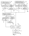
- FIG. 1 An exemplary calibration arrangement for a colorimeter, in this particular case, an imaging colorimeter 1, is shown in Fig. 1 .
- the imaging colorimeter 1 is illuminated with light of different spectra from a homogenous light source 2.
- the homogeneous light source 2 is equipped with an illumination unit 3 that is connected to a light-emission control unit 4.
- the illumination unit comprises an array of different calibration light sources 8, for example LEDs or tungsten lamps of different color that represent the calibration illuminants.
- a sectional view of the illumination unit is also shown in Fig. 1 .
- the light-emission control unit 4 causes the illumination unit to irradiate light of different spectra into a body of the homogenous light source 2 by activating different calibration light sources 8 successively.
- the homogeneous light source 2 is realized as an Ulbricht-sphere.
- the light of the illumination unit is diffusively reflected from the spheres inner surface, such that a homogenous spectral radiance of the light along the spheres inner surface is achieved.
- the Ulbricht-sphere is particularly suitable to send out the light of the illumination unit with homogenous spectral radiance.
- the illumination-unit 3 in turn, fills the homogenous light sources body with light.
- the homogenous light source couples out this light 5 towards the imaging colorimeter 1, in a homogenous manner.
- a reference spectrometer 6 derives reference tristimulus values and reference chromaticity values by convoluting color matching functions with measured spectral values of the light 5.
- the reference spectrometer and the colorimeter to be calibrated receive both the light 5 from the homogenous light source 2 originating from the same calibration light source 8.
- the light 5 is coupled out towards the imaging colorimeter 1 directly and guided to the reference spectrometer 2 via a light duct 9.
- the derivation of calibration factors 13, 14 (not shown in this Figure) for the imaging colorimeter 1 is in this example carried out by a personal computer 7.
- the personal computer 7 controls the light-emission control unit 4 by setting the order in which the calibration light sources 8 included in the illumination unit 3 are activated.
- An exemplary method of calibrating a colorimeter starts with successively activating the calibration light sources 8 that emit light of different spectra, in the activity at box S 1.
- an index i reaching from 1 to m, is assigned to each calibration light source. Therefore, light of a spectrum 1 has the index 1, while light of a spectrum 2 has the index 2, etc.
- the imaging colorimeter 1 is successively illuminated with that light by means of the homogenous light source 2. Altogether, the imaging colorimeter 1 is illuminated by the light of m different calibration light sources.
- the activities at box S2 and S3 are performed for each successively activated calibration light source 8.
- n sensings is obtained by the imaging colorimeter 1.
- the activity at box S2 thereby leads to m sets of n (in this example six) sensings 6 measured by the imaging colorimeter 1.
- One set of chromaticity values and one reference luminance are measured by the reference spectrometer 2 for each light of a different spectrum emitted by a calibration light source 8.
- the m sets of reference chromaticity values x ref i / y ref i 11 and the set of m reference luminances Y ref i 12 represent the known chromaticity values and the known values of the achromatic primary (luminance Y).
- the m sets of n sensings s i 10 and the m sets of reference chromaticity values 11 are used in the activity at box S4, to obtain a chromaticity-optimized set of calibration factors M x/y .
- This activity at box S4 is further described in conjunction with Fig. 3 .
- the m sets of n sensings 10 and the set of m reference luminances Y ref i 12 are used in the activity at box S5 to obtain a set of calibration factors M Y , optimized with respect to luminance Y 14. This activity is further described in conjunction with Fig. 4 .
- the first part of the block diagram of Fig. 2 that is related to this calibration procedure, is therefore separated with a dashed line from the second part of this block diagram.
- This part of the block-diagram is related to applying the calibration factors when using a colorimeter equipped with those calibration factors 1' to obtain XYZ readings, optimized with respect to chromaticity and for the achromatic primary, when measuring light 5 with the colorimeter.
- a set of n sensings is measured by this colorimeter 1'.
- the chromaticity-optimized set of calibration factors M x/y 13 is applied to this set of n sensings in the activity of box M2.
- the set of calibration factors M Y optimized with respect to luminance Y 14 is applied in the activity at box M3 to the set of n sensings obtained in the activity of box M1.
- a scaling factor is determined that is a function of the luminance Y' of the chromaticity-optimized tristimulus values X', Y', Z' 15 and the optimal intensity value of the luminance Yo 16.
- the scaling factor is the ratio between those two luminances, namely Y 0 Y ⁇ .
- the chromaticity-optimized tristimulus values X', Y', Z' 11 are multiplied by the scaling factor determined in the activity at box M4.
- the final tristimulus values X final , Y final and Z final 17, i.e. the tristimulus values produced by the colorimeter are obtained.
- box S4 - choosing the chromaticity optimized set of calibration-factors M x/y illustrated in Fig. 2 - are shown in more detail in Fig. 3 :
- the root-mean-square of chromaticity distances D i chrom is set up as a function of a variable set of calibration factors M x/y .
- the set of variable calibration factors M x/y is applied to a vector comprising the signals measured by the n (in this example six) sensings s i .
- the set of calibration factors M x/y is applied by a matrix multiplication that yields three tristimulus values X i , Y i and Z i as its result.
- Chromaticity values x cam i , y cam i are determined as a function of these tristimulus values and are therefore a function of the set of variable calibration factors M x/y .
- the chromaticity-related root-mean-square F chrom is minimized by adjusting the variable set of calibration factors M x/y . Choosing the set of calibration factors that yields a minimal root-mean-square F chrom is carried out, in this example, by applying a Nelder-Mead algorithm on the chromaticity-related root-mean-square F chrom .
- the activity of setting up the root-mean-square of the achromatic distances F achrom and subsequently choosing the set of calibration factors that minimizes this root-mean-square is shown in more detail in Fig. 4 .
- the activity of setting up the root-mean-square F achrom , related to the achromatic primary is depicted in S5 1 and is analogous to the activity of setting up the chromaticity-related root-mean-square F chrom .
- a variable set of calibration factors represented by the matrix M Y
- M Y the matrix of calibration factors
- the respective n sensings are taken out of the m sets of n sensings s i 10.
- the result of these matrix multiplications is a luminance Y 0i for a certain calibration light source with a certain index i, expressed by the set of variable calibration factors.
- the achromatic distances D i , achrom are the Euclidian distances between (i) the reference luminances Y ref i , taken from the set of m reference luminances 12, for a certain calibration light source 8 with index a certain index i and (ii) the result of the above mentioned matrix multiplication, namely the luminance Y 0i for the light of the same calibration light source 8.
- an achromatic-distance related root-mean-square F achrom is set up.
- the summands of this root-mean-square are the achromatic distances D i, achrom for each calibration light source 8. These summands are weighted in analogy to the summands of the chromaticity-related root-mean-square of Fig. 3 .
- the set of calibration factors optimized with respect to luminance Y is chosen, such that the achromatic-distance related root-mean-square F achrom is minimized.
- the set of calibration factors, optimized with respect to luminance Y represents the set of calibration factors optimized with respect to the achromatic primary.
- the root-mean-square F achrom can be minimizied in the same way as described above.
- the "ordinary least square" approach can be used to obtain the set of calibration factors optimized with respect to the achromatic primary non-iterative. This is the particular case of Y, because the equation system for minimizing the root-mean-square F achrom is linear.
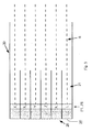
- the exemplary sensor arrangement 20 provides the signals measured by the six sensings at once.
- the exemplary light sensor arrangement of Fig. 5 is capable of providing six sensings simultaneously, by means of six separate beam paths 21, guiding light 5 to be measured to six separate photosensors with filters F1-F6 of different spectral sensitivities.
- the filters F1-F6 are tristimulus filters X 1 , X 2 , Y and Z and two additional filters K and L. These two additional filters compensate deficiencies of the tristimulus filters in certain parts of the spectrum. In this example, the tristimulus filter taken alone would lead to measurement errors when measuring light with a wavelength of 460 to 560 nm, as shown in Fig. 12 .
- FIG. 6 Schematic sectional views of an alternative sensor arrangement 20', arranged to obtain the six signals measured by the sensings sequentially, are depicted in Fig. 6 .
- a lense image of the light 5, provided by a lense 21 is chromatically filtered by a filter F1, in this example a X 1 filter.
- the light 5 passing filter F1 is converted into electrical signals corresponding to the intensity of the light by a monochromatic camera sensor in CCD technology 25'.
- the monochromatic camera sensor 25' is arranged to measure a spatially extended light distribution.
- the sensor arrangement 20' of Fig. 6 functions as a imaging system.
- Different filters F1-F6 can be placed in a filtering position mechanically, by rotation of the filter wheel 23 to provide six sensings. Each pixel can be seen as a separate colorimeter. However, provided that the components of the sensor arrangement 20' have homogenous properties, the same set of calibration factors can be applied for each pixel depicted by the sensor arrangement 20'.
- the sectional view of this sensor arrangement 20' is cut once along the B-B axis (shown by dashed lines) and once along the A-A axis also shown by dashed lines. Two front views of these slices are also depicted by Fig. 6 .
- the slice view on the cut along the A-A axis shows a front view of the filter F1
- the slice view on the cut at the B-B axis shows a front view on the monochromatic camera sensor (CCD technology) 25'.
- the six sensings are obtained by sequentially moving the filters F1-F6 into a filtering position, that is, in this example, the position between the beam path 21 and the camera sensor 25".
- FIG. 7 A schematic view of an imaging colorimeter 1', equipped with the sensor arrangement 20, 20' and the chromaticity-optimized (here x/y - optimized) set of calibration factors 13 and the set of calibration factors optimized with respect to luminance 14 is given by Fig. 7 .
- This processing system comprises a central processing unit (CPU) 41 and an internal storage 42.
- the CPU 41 is programmed to apply the chromaticity-optimized calibration factors 13 and the set of calibration factors optimized with respect to luminance Y 14, stored in the internal storage 42, to the signals measured by the n sensings.
- the resulting chromaticity-optimized values X' Y' Z' 11 and the resulting optimized luminance value Yo are stored in the internal storage 42 (not shown in Fig. 7 ).
- the CPU 41 is further programmed to calculate the scaling factor that is a function of the optimized luminance value Yo and the luminance value Y', namely Y 0 Y ⁇ .
- the CPU 41 is programmed to scale the chromaticity-optimized values X' Y' Z' by these factors to obtain the final tristimulus values X Y Z 17.
- the imaging colorimeter 1' is also equipped with an I/O interface 80 in order to be connectable to personal computers for data exchange and/or to be connectable to the internet via this interface, for example for retrieving sets of calibration factors from the internet.
- the I/O interface is, for example, a USB port.
- the imaging colorimeter 1' may alternatively be equipped with an internet connection for retrieving sets of calibration factors from the internet.
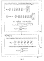
- Spectral curves representing the filter function of the tristimulus filter X 1 , X 2 , Y and Z of the sensor arrangement are illustrated by Fig. 8 .
- Filter curve 46 represents the X 1 + X 2 filter response that mimics the tristimulus primary X response of a human standard observer.
- Filter curve 45 represents the Z filter response and filter curve 47 represents the Y filter response.
- the manufacturing process of such filter allows only to approximate the desired transmission curve to a certain degree. Deviations of several percent in certain spectral regions have to be expected.
- the responses of the Z filter and the X 2 filter (the X 2 filter is the filter that yields the peak of the X 1 + X 2 filter curve 46 between 500 and 700 nm) have a deviation from an ideal filter curve.
- the deviating part of the Z filter response curve 45 is marked by reference sign 45', whereas the deviating part of the X 2 filter response is marked by reference sign 46'.
- These deviations of the filter curves are compensated by the two additional filters K and L. This compensation is illustrated in Fig. 8 by the dashed lines that complement the X 1 + X 2 filter curve 46 and the Z filter curve 45.
- the sensor arrangement is equipped with more than six filters.
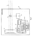
- FIG. 9 An exemplary camera system 35, arranged to produce values of X, Y, Z on the basis of RGB measurements, is shown in Fig. 9 .
- This exemplary camera system includes the imaging colorimeter 1', equipped with sets of calibration factors 9, 10 that enable the colorimeter to produce tristimulus values that are optimized with respect to chromaticity and to luminance 12.
- An RGB-sensor arrangement 30 and a processing system 40' are also part of the camera system 35.
- Light 5 that enters the camera system 35 either enters the RGB-sensor arrangement directly or, if the light 5 originates from a reference spot 5ref, is partially distracted by a beam splitter 31. Hence, the light originating from the reference spot 5ref is shared between the imaging colorimeter 1 and the RGB-sensor arrangement 30.
- reference X, Y, Z values 51 measured by the calibrated imaging colorimeter 1' as well as RGB values can be determined for light originating from said reference spot 5ref.
- the reference spot is, for example, a spot in the center of the light distribution.
- Those reference X, Y, Z values and the RGB values 51 are stored in the internal storage 42' of the camera system 35 during or after a measurement of light 5.
- the reference X, Y, Z values 51 are used to derive mapping factors 90, 91, that provide a mapping from RGB values 50, measured by the RGB-sensor arrangement 30, to X, Y, Z values. Exemplary methods for determining these mapping factors 90, 91 are illustrated by the block diagrams of Fig. 10 and Fig. 11 , described below.
- mapping factors 90, 91 are carried out by a CPU 41' integrated in the processing system 40' and connected to the internal storage 102. Once those mapping factors 90, 91 have been determined, the measured RGB values 51 can be mapped to the X, Y, Z values without colorimeter reference measurements. Assuming the spatial light distribution and the RGB-sensor response are fairly homogeneous, the mapping can by successfully applied for the whole image of the RGB sensor.
- the processing system is connected to an I/O interface 80', e.g. an USB port, in order to be capable of sharing data with external storages such as computers or internet servers.
- the camera system illustrated by Fig. 9 is arranged to derive mapping factors from RGB values to X, Y, Z values, by means of its processing system 40'.
- a first method for deriving this set of mapping factors 90, 90', carried out by the camera system 35 is illustrated by Fig. 10 .
- the RGB-sensor arrangement 30 measures the RGB values 50 for that light 5ref in the activity of box D1.
- reference X, Y, Z values 51 of that light 5ref are measured by the calibrated imaging colorimeter 1'.
- a set of mapping factors, already stored in the colorimeter that serves as a set of pre-calibration factors M RGB ⁇ XYZ is applied to the RGB values 50 in the activity at box D3.
- the mapping from RGB values to XYZ values is accomplished by applying a 3 x 3 matrix (representing the set of mapping factors) to the RGB values represented by a 3 x 1 vector.
- the resulting X, Y, Z values are compared with the reference X, Y, Z values measured by the imaging colorimeter 1 in the activity at box D4.
- a set of deviation-factors 70 is determined.
- a deviation factor for each matrix row of the matrix including the already stored calibration factors can be found.
- Such deviation factors are for example d x d y d z .
- the set of already stored mapping factors is corrected with the set of deviation factors to obtain the final set of mapping factors 90.
- mapping factors presented in the "general description" part is then modified as follows and yields the following tristimulus values, when carrying out the activity at box D5:
- X Y Z d x 0 , 4124564 d x 0 , 3575761 d x 0 , 1804375 d y 0 , 2126729 d y 0 , 7151522 d y 0 , 0721750 d z 0 , 0193339 d z 0 , 1191920 d z 0 , 9503041
- the sets calibration factors can for example also be derived "from scratch", i.e. without modifying an already stored set of mapping factors.
- Such sets of calibration factors - derived from scratch - can be used as pre-calibration factors in the method described above.
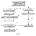
- the block diagram illustrated by Fig. 11 demonstrates an exemplary method to a set of mapping factors that way.
- the exemplary derivation of the mapping factors "from scratch", illustrated by Fig. 11 is carried out by measuring three different calibration illuminants, illuminating the reference spot.
- the primaries of the calibration illuminants originate in this example from a device under test (DUT).
- a typical device under test (DUT) for such an RGB-camera system is for example a display. It can be addressed to provide a first illuminant with red light, a second illuminant providing green light, a third illuminant providing blue light, e.g. the primary colors of the typical DUT.
- the red light from the reference spot 5R is measured by the RGB-sensor arrangement in the activity at box U1 and measured with the colorimeter in the activity at box T1. These activities result in a first set of R 1 , G 1 , B 1 values of this light 75 and reference X 1 , Y 1 , Z 1 values for that red light 75R with an index 1.
- Analogue activities T2 and T3 are carried out for green light 5G, resulting in sets of R 2 , G 2 , B 2 (76) and X 2 , Y 2 , Z 2 (76R) values with index 2 and for blue light resulting in R 3 , G 3 , B 3 values 77 and reference X 3 , Y 3 , Z 3 values 77R with index 3.
- mapping can then be found by inverting the transposed RGB-result matrix and a right handed multiplication with the XYZ result matrix in activity T5.
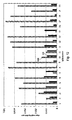
- the chromaticity-distances in xy color space 100, 101 shown in Fig. 12 were determined for 20 different light sources, i.e. light sources having different spectra.
- the chromaticity distances 100, illustrated by the hatched bars in Fig. 12 were determined by minimizing the color-distance of the tristimulus values (XYZ optimization) according to prior art.
- the chromaticity-distances 101 obtained by minimizing chromaticity-differences according to the invention (x/y optimization), are illustrated by the filled-out black bars of Fig. 12 . As can be seen from the Figure, the chromaticity-distances 101 are substantially smaller than the chromaticity distances 100.
Abstract
Description
- The invention relates to the field of color-measurement, more specifically to the field of measuring values of primaries of a human standard-observer based color space, such as the tristimulus values X, Y, Z, or values of the primaries L* a* b* of the CIELAB color space, and in particular to the field of calibrating multi-filter based colorimeters, multi-filter based imaging colorimeters and to colorimeter systems that are based on RGB-imaging systems.
- In the field of colorimetry two basic measurement principles are known. In the first principle the light is measured spectrally resolved. Integration with weighting according to the eye sensitivity of the "standard observer" defined in the CIE 1931 XYZ color space are applied to receive the tristimuli values of XYZ. In the second principle the eye sensitivity is mimicked with a filtered photosensor. The filters are made either of bulk absorber (color glass filter) or with interference filters. A minimum of three filters is needed to measure up to the trichromaticity of human vision. Often a fourth filter is used to ease the technical realization of the double lobbed nature of the X channel. More channels are can be used to overcome technical limitations of the accuracy of the sensitivity response of the filter / sensor pair.
- Kosztyán et al, "Matrix-based color measurement correction of tristimulus colorimeters", Applied Optics, Vol. 49, No. 12, 20 April 2010, p. 2288-2302 describe a measurement of tristimulus curves of a plurality of test light-sources with known tristimulus values (and therefore known chromaticity values) with a multi-input-channel colorimeter. Each input-channel of the colorimeter provides an output signal. These output signals are used to calculate three corrected tristimulus values by applying a matrix to these signals. The matrix maps the output signals to the tristimulus values. The matrix elements are determined by minimizing an arithmetic mean of the color-distances

- According to a first aspect, a method of calibrating a colorimeter arranged to measure light with a sensor arrangement providing n sensings with different spectral sensitivities, wherein n is a number greater than or equal to four, and measure that light in the form of three primaries of a human-standard-observer-based color space, wherein one of the three primaries is an achromatic primary is provided. The method comprises:
- generating m sets of n sensings for m calibration illuminants with known values of the three primaries, wherein m is a number greater than n.
- determining a first set of calibration factors that yields chromaticity-optimized values of the primaries when applied to signals measured by the n sensings by minimizing a norm of chromaticity distances of all calibration illuminants between (i) the chromaticity values retrieved by applying the first set of calibration factors to the signals measured by the n sensings, and (ii) the known chromaticity values.
- determining a second set of calibration factors that yields an optimized value of the achromatic primary when applied to the signals measured by the n sensings by minimizing a norm of achromatic distances between (i) the values of the achromatic primary retrieved by applying the set of calibration factors to the signals measured by the n sensings, and (ii) the known values of the achromatic primaries for all calibration illuminants,
- According to a second aspect, a colorimeter for providing measurements of light with regard to primaries of a human-standard-observer-based color space, the colorimeter is equipped with sets of calibration factors obtainable by the method of any one of the claims 1 to 13. Alternatively, a colorimeter is provided that is arranged to access such sets of calibration factors from an external storage. The colorimeter comprises:
- A sensor arrangement providing n sensings of the light with different spectral sensitivities, n being a number greater than or equal to four,
- A processing system arranged to measure the light with respect to the three primaries of the human-standard-observer based color space from the n sensings, by:
- applying a first set of calibration factors to signals provided by the sensor arrangement to obtain chromaticity-optimized readings of the tristimulus values,
- applying a second set of calibration factors to signals provided by the sensor arrangement to obtain the optimized reading of the achromatic tristimulus value,
- and by combining the results to an optimized reading both in chromaticity and for the achromatic primary.
- According to a third aspect, the colorimeter of the previous aspects is equipped with an imaging sensor. Each pixel can be treated as an individual colorimeter but resulting in a measurement of a spatially extended light distribution.
- Another aspect relates to yet another camera system for providing intensity values of a spatially extended light distribution with respect to three primaries of the human-standard-observer-based color space. The camera system comprises an RGB-sensor arrangement sensitive to the spatially extended light distribution and a spot colorimeter like the one related to the second aspect. Light, originating from a reference spot of the spatially extended light distribution, is shared between the colorimeter and the RGB-sensor arrangement, whereby values of the light of the reference spot are determined with respect to the three primaries of the human-standard-observer-based color space by means of the colorimeter and are measured with respect to RGB by means of the RGB-sensor arrangement. The camera system is arranged to derive a set of mapping factors, and/or to adjust a set of already stored mapping factors, to map RGB values to values with respect to the three primaries of the human-standard-observer-based color space. Thereby the camera system provides with a single image acquisition values of the light of the spatially extended light distribution with respect to the three primaries of the human-standard-observer-based color space with an accuracy close to the one achieved with the spot colorimeter.
- Other features are inherent in the disclosed methods and systems or will become apparent to those skilled in the art from the following description of examples and its accompanying drawings.
- According to a first aspect a method of calibrating a colorimeter is provided. The term "colorimeter" refers generally to devices that measure color and luminosity of a certain spot illuminated with light. In particular, colorimeters that are arranged to mimic the colorperception of a human-standard-observer, providing readings of primaries of a human-standard-observer based color space are considered for the method.
- The colorimeter is arranged to measure light with a sensor arrangement providing n sensings with different spectral sensitivities. The sensor arrangement comprises elements that convert light into electric signals (light sensors), such as photo diodes, CCD or CMOS sensors. Those photosensors are equipped for example with filters placed in a beam path from the light to the photosensors. For example, a photodiode-array, comprising six elements with separate beam paths leading to them, is provided. In this exemplary sensor arrangement, one specific spectral filter is provided in the beam path of each photodiode element. Another example to realize a sensor arrangement is to place tristimulus filters, in the beam path in front of a respective photosensor. The sensor arrangement of the colorimeter provides n sensings of light that is measured by the colorimeter, wherein n is a number greater or equal four. A sensing refers to a measurement of a particular quality of the light measured, for example, one sensing corresponds to the response of an X1 sensor of the sensor-arrangement, e.g. the photodiode response after the light was transmitted through an X1 filter, and another sensing corresponds to the response of the X2 sensor (having an X2 filter). X1 filters and X2 filters mimic the response to of a human-standard-observer's eyes cone-cells in different spectral regions.
- One of the primaries for which values are produced by the colorimeter is an achromatic primary. The achromatic primary of a human-standard-observer-based color space is the primary that yields rather the intensity of light rather than its color. Examples for human-standard-observer based color spaces are the X, Y, Z color space, where the X, Y and Z responses are the tristimulus values of a human-standard-observer and Y is the achromatic primary defined as luminance, the xyY color space with Y as the achromatic primary, the CIELAB L*, a*, b* color space, where L* is the achromatic primary, also referred to as "lightness", or the CIELUV L*, u*, v* color space, having the same achromatic primary L*.
- In a first activity, m sets of n sensings are generated for m calibration illuminants with known values of the three primaries, wherein m is a number greater than n. Hence, n sensings are obtained for each calibration illuminant of altogether m calibration illuminants. The term "calibration illuminant" means, for example, a real light source used to illuminate a real colorimeter. However, also a simulated light source used in embodiments in which the calibration is simulated by a computer using a computer-model of a real colorimeter, shall be covered by the term "calibration illuminant". The values of the three primaries of the calibration illuminants are known, as they are either measured or predetermined. If the values of the three primaries are predetermined, the calibration illuminants have been, for example, calibrated beforehand to emit light with these primaries and/or chromaticity values.
- In a second activity, a first set of calibration factors herein further referred to as the "chromaticity-optimized set of calibration factors" that yields chromaticity-optimized values of the primaries of the human-observer-based color space, when applied to signals measured by the sensings, is determined. The term "chromaticity-optimized set of calibration factors" as well as the term "chromaticity-optimized values of the primaries of the human-observer-based color space" is used in this document to make clear that this set of calibration factors resulting from the method for calibrating a colorimeter yields, when applied to the signals measured by the sensings, values of the primaries of the human-standard-observer based space with chromaticity values that have a minimal norm of chromaticity-distances for all the corresponding calibration illuminants.
- The chromaticity-optimized set of calibration factors, is determined by minimizing a norm of chromaticity distances. The chromaticity-distances are the distances between (i) the chromaticity values retrieved by applying the set of calibration factors to the signals measured by the n sensings, and (ii) known chromaticity values for all calibration illuminants. To provide a particular example, the norm of the chromaticity distances is a mathematical norm, for example, given by a root-mean-square of these chromaticity-distances obtained for the calibration illuminants. This norm can be seen as an absolute value of the measurement error of the colorimeter.
- By choosing a set of calibration factors that minimizes the norm of chromaticity distances, measurement errors of a colorimeter equipped with those calibration-factors with respect to chromaticity values are reduced. If a plurality of filters provide only a deficient filter function, e.g. due to production-related errors, those deficiencies can be compensated by the set chromaticity-optimized calibration-factors, resulting from these minimizations.
- Choosing this set of calibration factors is, for example, achieved by iterative numerical methods, such as non-linear optimization algorithms. These methods vary a set of variable calibration-factors until the norm of the chromaticity-distances is minimal. Alternatively, the minimization of the norm of the chromaticity-distances can be achieved by using analytical mathematical methods such as the well-known Lagrange method.
- An example for the determination of such a chromaticity-difference as a function of the set of calibration factors is given in the following:
- A set of six sensings, obtained by measuring the calibration illuminant i (i is a number from 1 to m, wherein m is number of calibration illuminants), is given by the vector si, each vector component represents a measurement signal caused by the illuminant i,

- The sensings X 1i,LC , X2i,LC Yi,LC , Z i,LC , Ki,LC and Li,LC stand for a sensings obtained by an X1 filter and an X2 filter (yielding the X tristimulus response) Y, Z tristimulus filters and two additional compensatory filters K and L for a certain calibration illuminant i, respectively. Mx/y is a set of calibration factors, in this example a 3x6 Matrix with calibration factors a11 to a36.

- The set of calibration factors Mx/y is transformed into the values of the primaries for illuminant i, namely: Xi, Yi, Zi:

- The chromaticity values, are given as a function of the values of those primaries by the following expressions:

wherein xcam i + ycam i + zcam i = 1. As the chromaticity value z cam i is dependent on the other two chromaticity values, only xcam i and ycam i are considered in this example. - The chromaticity distance Di, chrom between the chromaticity xcam, i, ycam i, i, produced by the transformation of the six exemplary sensings si, for a calibration-illuminant i and the known chromaticity of the calibration illuminant i xref i, yref i is given by the distance between a vector comprising Xcam, i, ycam i, and a vector comprising xref i, yref i.

- This chromaticity distance Di, chrom is defined by, e.g. an L1 or an L2 norm.
- After determining the chromaticity-distances Di, chrom, the chromaticity-optimized set of calibration factors is, as mentioned above, for example, determined by choosing the set of calibration factors that minimizes the norm of chromaticity distances for all the corresponding calibration-illuminants. The specific example of minimizing a root-mean-square as an example of a norm of chromaticity-distances when choosing the set of calibration factors is further explained below.
- In a third activity, a second set of calibration-factors , herein further referred to as a set of calibration factors optimized with respect to the achromatic primary - that yields an optimized intensity value of the achromatic primary, when applied to the signals measured by the sensings, is determined. The terms "optimized with respect to the achromatic primary" and "optimized intensity value of the achromatic primary" are also used in this document to make clear that the set of calibration factors resulting from the method yields, when applied to the signals measured by the sensings, values of the primaries of the human-standard-observer based space with an achromatic primary that has a minimal norm of the achromatic distances for all the calibration illuminants, which is further explained below.
- The set of calibration factors optimized with respect to the achromatic primary is determined by minimizing the norm of achromatic distances. The achromatic distances are defined as the distances between (i) the values of the achromatic primary retrieved by applying the set of calibration factors to the signals measured by the n sensings, and (ii) known values of the achromatic primary for all calibration illuminants. To provide a particular example, also the norm of the achromatic-distances is a mathematical norm, such as a root-mean-square of these achromatic-distances obtained for the calibration illuminants. The norm of the achromatic-distances can be seen as absolute value of the measurement error of the colorimeter too.
- Thus, determining this achromatic-optimized set of calibration-factors comprises, for example, choosing the set of calibration-factors that minimizes the norm of said achromatic distances, as described above and hereinafter.
- By choosing this set of calibration factors the measurement error of a colorimeter equipped with those calibration factors optimized with respect to the achromatic primary, is reduced, as already described in conjunction with the determination of the set of chromaticity-optimized calibration factors. The set of calibration factors (being a function of the set of calibration factors to be chosen) is also, for example, chosen such that the norm of the achromatic-distances is minimized. The specific example of minimizing a root-mean-square as an example of a norm of these achromatic-distances obtained for a plurality of calibration illuminants, is further explained below.
- Choosing this set of calibration factors, for example, achieved by iterative numerical methods, such as non-linear optimization algorithms. These methods vary a set of variable calibration-factors until the norm of the chromaticity-distances or the norm of the achromatic distances is minimized.
- Alternatively, this set of calibration factors that minimizes the norm of the achromatic distances is chosen, for example, by using analytical mathematical methods, analogous as described in conjunction with choosing the set of calibration factors that minimizes the norm of the chromaticity-distances.
- An example of determining an achromatic-distance is described in the following: The six signals measured by the sensings si, that were already introduced in the above example, are transformed into the achromatic primary Y0i by a set of calibration factors represented by the matrix MY, as follows:

- MY is a 3 x 6 - matrix with entries (calibration-factors) b11 to b36:

- X0i and Z0i are redundant in this example, therefore the transformation could also be achieved by a 1 x 6 Matrix with calibration factors b11 to b16, as shown by the formula reproduced below:

- The achromatic distance Di, achrom, i.e. the distance between Y0i and the known achromatic primary of calibration illuminant i, namely Yref i, is given by:

- This difference Di, achrom is defined by, e.g. a L1 or a L2 norm.
- After determining the achromatic-distances Di, achrom, the set of calibration factors optimized with respect to the achromatic primary is, as mentioned above, for example, determined by choosing the set of calibration factors that minimizes the norm of the achromatic-distances for corresponding calibration-illuminants.
- The activity of choosing the set of calibration factors that minimizes the norm of the achromatic distances and the activity of choosing the set of calibration factors that minimizes the norm of the chromaticity-distances are carried out independently from each other.
- The resulting chromaticity-optimized set of calibration factors corresponds to the set of calibration factors that minimizes the norm of the chromaticity-distances of all calibration illuminants, whereas the resulting set of chromaticity factors optimized with respect to the achromatic primary corresponds to the set of calibration factors that minimizes the norm of the achromatic distances of all calibration illuminants.
- One consequence of separating these two choosing activities is that the intensity value of the achromatic primary that is obtainable by applying the chromaticity-optimized set of calibration factors to signals measured by the n sensings, is different to the intensity value of the achromatic primary that is obtainable by applying the set of calibration factors optimized with respect to the achromatic primary to those signals. The former is part of a set of values of primaries that have optimized chromaticity values, the latter is the optimized intensity value itself.
- Carrying out the choosing activities simultaneously would lead neither to the chromaticity-optimized set of calibration factors nor lead to the set of calibration factors optimized with respect to the achromatic primary. The achromatic primary (once expressed as a function of the set of the set calibration factors that is chosen to minimize the norm of the chromaticity-distances and once expressed as a function of the set of calibration factors that is chosen to minimize the norm of the achromatic distances) would simultaneously be part of the first choosing activity and also the second choosing activity. As a result a compromise between those contradictory criterions that should be fulfilled by the first and second choosing activity would be found for the parts of the sets of calibration factors that influence the achromatic primary. Hence neither of the two sets of calibration factors would be optimal.
- Both sets of calibration factors together enable the colorimeter, when measuring light after the calibration, to provide optimized readings both in chromaticity and for the achromatic primary.
- The term "readings" referrers to final measurement values of light with respect to the three primaries.
- The two sets of calibration factors obtained by the method are (i) a chromaticity-optimized set of calibration factors and (ii) a set of calibration factors optimized with respect to the achromatic primary. The colorimeter is arranged to measure light after the calibration. Also a camera using the functional elements of the colorimeter, such as a photodiode array equipped with different filters to obtain the n sensings as described above is to be understood as a colorimeter in the above sense.
- The colorimeter provides optimized readings both in chromaticity and for the achromatic primary due to the two sets of calibration factors. The set chromaticity-optimized set of calibration factors, for example, enables the colorimeter to provide optimized readings of the chromaticity values xy in the xyY human-observer based color space, or the a*, b* chromaticity values of the CIELAB color space, or the u*, v* chromaticity values of the CIELUV color space.
- In the above example, the chromaticity optimized calibration factors with optimized x/ychromaticity values when applied to the signals measured by the sensings si. The optimized chromaticity readings x/y can be obtained from these tristimulus values as they are a function of the tristimulus values obtained by applying the set of calibration factors:

- Other examples, especially related to the CIELAB and CIELUV will be explained in later sections of the document.
- The set of calibration factors optimized with respect to the achromatic primary enables the colorimeter, in turn, for example, to provide optimized readings of the values of the achromatic primary Y in the xyY color space, or L* in the CIELAB or CIELUV color space.
- In the above mentioned first activity, m sets of n sensings for the m calibration illuminants with known values of the three primaries are generated.
- In some embodiments, the colorimeter is illuminated separately with real calibration illuminants having different spectra (contrary to simulated calibration illuminants mentioned above). Such real calibration illuminants with different spectra are, for example, light emitting diodes (LED), tungsten lamps, halogen lamps, fluorescence light source or the like. However the term "calibration illuminant" relates to source of light with different spectra in general. Therefore also a single light source, driven to emit light of different spectra by adjusting, for example its temperature or the chemical composition of the light emitting components of the illuminant (for example by heating up different chemical elements emitting light of different spectra when heated) is covered by the term "calibration illuminant". If different groups of light sources emit light simultaneously this is too seen as a "calibration illuminant". The colorimeter is then separately illuminated by different groups of light sources, each different group corresponding to a calibration illuminant.
- In some embodiments, the m sets of n sensings are generated by measuring the spectral sensitivity of the n sensors and the spectral emission of the calibration illuminants. The n sensings are computed thereof. The n sensings are, for example, computed by applying a computer model of a sensor arrangement using the measured spectral sensitivity of the n sensors and the measured spectral emission of the calibration illuminants.
- The known values of the three primaries of the human-standard-observer-based color space of the calibration illuminants are measured or predetermined, as already mentioned above. The values of the corresponding achromatic primary and/or the chromaticity values of those primaries are, for example, measured by illuminating the colorimeter and a very precise reference-spectrometer, such as a high quality spectrometer using color-matching-functions to obtain the values of the primaries and at the same time measuring the same calibration-illuminants.
- Therefore, the colorimeter and the reference-spectrometer are illuminated by the same calibration illuminants, and the known value of the primaries of these calibration illuminants is obtained by measuring the light of the respective calibration illuminant with said reference-spectrometer.
- As already mentioned above, when measuring light with the colorimeter, the chromaticity-optimized set of calibration-factors is applied to signals provided by the sensor arrangement originating from the light to obtain chromaticity-optimized values of the primaries. The set of calibration-factors optimized with respect to the achromatic primary is also applied to these signals to obtain the optimized value of the achromatic primary.
- This is, for example, carried out by multiplying the matrix Mx/y of the above example, representing the chromaticity-optimized set of calibration-factors with a vector of the signals measured by the sensings s and by multiplying the matrix MY of the above example, representing the set of calibration factors optimized with respect to the achromatic primary, with the same vector s:


- By applying the chromaticity-optimized set of calibration factors Mx/y to the signals measured by the sensings, values of primaries with optimized readings in chromaticity x/y are obtained, whereas by applying the set of calibration factors optimized with respect to the achromatic primary MY, optimized readings with respect to the achromatic primary Y are obtained. In the case that optimized readings in the xyY color space should be obtained and x/y readings were derived from the optimized (X', Y', Z') readings, these x/y readings in combination with the X reading would already be the desired readings in the xyY color space.
- In the case that, for example, tristimulus values (X, Y, Z) with optimized chromaticity values x/y and also an optimized achromatic primary Y are the desired readings, the two readings and the corresponding calibration factors are, for example, used in the following way to provide these X, Y, Z, readings optimized both in chromaticity and for the achromatic primary:
- The optimized readings in chromaticity x/y are scaled with a factor including the optimized intensity value of the achromatic primary Yo and the intensity value of the achromatic primary of the chromaticity-optimized primaries Y'.
- By performing this scaling, the chromaticity values of the chromaticity-optimized values of the primaries remain unchanged, thereby the chromaticity values of the chromaticity-optimized values of the primaries still have a minimal chromaticity-distance to the known chromaticity values of the calibration illuminants. Hence, e.g. tristimulus chromaticity values remain optimal, regardless of the scaling. This is explained by the fact that every factor multiplied with a chromaticity, e.g. the factor three as shown below, which is equally applied to all three values of primaries, cancels out and has therefore no influence on chromaticity. This can be demonstrated by the example of tristimulus primaries X, Y, Z and their respective chromaticity values x, y:

- This scaling-factor is, for example, a function of those two primary values f(Y0, Y') (the reading of the achromatic primary of the chromaticity-optimized readings of the primaries and the optimized reading of the achromatic primary). Such an exemplary scaling operation is mathematically expressed by:

- In this expression, the vector representing the chromaticity-optimized readings of the primaries X' Y', Z', is multiplied with the factor f(Yo, Y') to obtain the final readings of the primaries produced by the colorimeter, namely X final, Y final, Z final.
- The factor f(Yo, Y') is given, for example, by the ratio between the achromatic primary Y' of the chromaticity-optimized reading of the primaries (X', Y', Z') and the optimized reading of the achromatic primary Y0, e.g. Yo divided by Y', such that the final readings of the primaries are then given by:

- By carrying out the scaling using this exemplary ratio, the chromaticity-optimized achromatic primary Y' is transformed into the optimized achromatic primary Y0, wherein the chromaticity values of the chromaticity optimized primaries X', Y', Z' remain unchanged.
- The result of this scaling are the final readings of the primaries X, Y, Z (tristimulus values), optimized both in chromaticity and for the achromatic primary Y.
- If only the chromaticity-optimized set of calibration factors were applied, the reading of the achromatic primary Y was, as a consequence, non-optimal, as the chromaticity-optimized set of calibration factors also shifts that achromatic primary.
- In some embodiments the chromaticity distances and/or the achromatic distances are Euclidian distances. Generically expressed, the chromaticity difference Di,chrom taken from the example described above is given by:

- This chromaticity distance is in this embodiment a Euclidian distance, given by the formula:

- Generally expressed, the achromatic difference Di,achrom taken from the example described above is given by:

- This chromaticity distance is in this embodiment a Euclidian distance, given by the formula:

- By using a Euclidian distance as the chromaticity distance and/or the achromatic distance, those distances correspond to distances in a Euclidian space. The Euclidian distance is positive definite, i.e. it results only in positive values for the distances Di,achrom and Di,chrom. Therefore, when these distances are minimized using a root-mean-square as the norm of the achromatic distances or chromaticity-distances, the root-mean-square can only be minimized by minimizing the chromaticity-distances or achromatic distances. This is the case here, as all summands are always positive and cannot cancel each other out.
- In some embodiments, the norm of the chromaticity-distances is a root-mean-square of the chromatic distances, obtained for the m calibration illuminants, and/or the norm of the achromatic distances is a root-mean-square, of the achromatic distances, obtained for the m calibration illuminants.
- Hence, the norm of chromaticity distances in this example given by a root-mean-square Fchrom of the chromaticity differences Di chrom, which reads:

wherein m is the number of calibration-illuminants for which a chromaticity-difference Di chrom is determined. - The norm of the chromaticity-distances is minimized as follows:

- The minimization is, for example, carried out by means of an iterative numerical method mentioned above. Such iterative numerical methods comprise varying a set of variable calibration factors in an iterative manner to until a minimal value of the root-mean-square is found. Examples for applicable numerical methods are the Nelder-Mead algorithm or other nonlinear programming algorithms, such as the Powell-algorithm.
- As start values for the variation of the variable calibration factors, for example, previously stored calibration factors can be used.
- Alternatively, as an analytical solution for the set of calibration factors can be determined in the case that the number of measured sensing n is equal to the number of calibration illuminants m, the set of calibration factors which is the solution of that problem for chosen calibration can serve as start values for the variation. Advantageously, n calibration illuminants are chosen that cover a broad part of the spectrum, when determining these start values.
- The chromaticity values of the primaries obtained by applying the chromaticity-optimized calibration factors to the signals measured by the sensings have a lower residual deviation from the known chromaticity values of the calibration-illuminants than chromaticity values of primaries that were determined by minimizing the differences between (i) just the primaries (Xcam i, Ycam i, Zcam i ) - not the chromaticity of the primaries - obtained by applying the calibration factors and (ii) the known primaries of the calibration illuminants (Xref i, Yref i, Zref i).
- Such a difference is given for a calibration-illuminant i:

- And therefore the root-mean-square Fcolor of those differences is given by:

- If the chromaticity-optimized set of calibration factors were determined by minimizing this root-mean-square Fcolor, the chromaticity values of readings for primaries resulting from applying this set to the signals measured by the sensings are, in general, non optimal.
- Alternatively or additionally, the norm of the achromatic distances is a root-mean square of the achromatic distances obtained for the m calibration illuminants (m is a number greater than n).
- This root-mean-square Fachrom of the achromatic differences Di achrom, is given by:

- Hence the criterion for finding the set of calibration factors optimized with respect to the achromatic primary by minimizing the norm given above, reads:

- The minimization is, for example, carried out by means of an iterative numerical method, as mentioned above.
- In some embodiments, the summands of the root-mean-square of the chromaticity distances have either uniform weights or, alternatively, non-uniform weights, i.e. at least one of the summands is weighted with a higher or lower weight than another summand.
- An exemplary root-mean-square of chromaticity distances, including weights for each summand, is given below:

wherein wi is the weight for calibration illuminant i and Di, chrom is the chromaticity distance for that calibration illuminant. - If the weights are non-uniform, the higher the weighting factor is, the higher the chromaticity distance for a certain calibration-illuminant, the more this chromaticity distances is prioritized by the iterative numerical method or variation method. Hence, the chromaticity distance for a certain calibration-illuminant, or the calibration distances for a certain group of calibration-illuminants will be, for example, minimized at the expense of chromaticity distances for other calibration illuminants.
- Alternatively or additionally, in some embodiments the summands of the root-mean square of the achromatic distances have either uniform weights or, alternatively, non-uniform weights, i.e. at least one of the summands is weighted with a higher or lower weight than that of other summand.
- An exemplary root-mean-square of achromatic distances with weighted summands is given below:

wherein w i is the weighting factor for calibration illuminant i and Di, achrom is the achromatic distance for that calibration illuminant. - The considerations made above for the root-mean-square of chromaticity-distances in conjunction with the behavior of the iterative numerical method or variation method in response to summands with uniform weights or non-uniform weights also hold true for the root-mean-square of achromatic distances.
- In some embodiments, in response to at least one chromaticity distance and/or at least one achromatic distance exceeding a given penalty-distance from a target value when varying the set of variable calibration factors, the at least one exceeding chromaticity distance and/or exceeding achromatic distance is weighted higher in the subsequent variation of the set of variable calibration factors than in the preceding variation of the sets of variable calibration factors, wherein the exceeding chromaticity distance and/or exceeding achromatic distance is weighted higher than the chromaticity distances and/or achromatic distances that do not exceed this penalty distance.
- The penalty distance is a given distance from the target value. The target value can either be arbitrarily chosen (predetermined) or may be a momentary value of a corresponding norm of the chromaticity distances or achromatic distances, such as a root-mean-square of chromaticity-distances or a root-mean-square of achromatic distances.
- This "limit and penalty" mechanism is, for example, applied after several "warm up runs" of an iterative minimization method, as penalizing a lot of chromaticity-distances/achromatic distances at this early stage might lead to numerical unstable behavior of standard nonlinear programming algorithms.
- By increasing the weight of an exceeding chromaticity-distance/achromatic distance in a norm of achromatic or chromatic distances, e.g. the root-mean-square of these distances, the exceeding chromaticity-distance/achromatic distance is minimized at the expense of the other chromaticity-distance/achromatic distance to be minimized.
- However, the overall result for the chromaticity-distances / achromatic distances is more uniform, i.e. confined within a range around the target value defined by the penalty distance, when this functionality is applied.
- In some embodiments, the sensor arrangement comprises n filter-photo sensors comprising n filters with different spectral sensitivities coupled to corresponding n photo sensors, to provide the n sensings simultaneously.
- The filter photo sensors comprise photo sensors that convert light into electric signals, such as photodiodes, charge-coupled devices (CCD) or complementary metal-oxide-semiconductor (CMOS) photo-sensors and corresponding filters. The filters are, for example, chromatic filters, such as X1, X2, Y or Z filters. In this embodiment at least four filters are used to obtain at least four sensings.
- These n filters are, for example placed on the corresponding photosensor so that they face the light measured, i.e. in the beam path of the light. For example, an array of photo sensors having six sub-arrays with separate beam paths leading to them, is provided. In this exemplary sensor arrangement, a different filter is provided in the beam path of each subarray.
- The filters have different spectral sensitivities. Additionally to the effects already mentioned, for example, a first set of filters can be used that provides an accurate filter function in a certain spectral region but a rather inaccurate in other spectral regions. This first set of filters is for example supported by a second set of filters that provides an accurate filter function right in that spectral region where the first set of filters is inaccurate and vice versa.
- The at least four sensings and therefore the corresponding at least four signals measured by the sensings are obtained simultaneously, as the same light is measured by the sensor arrangement equipped with n different filters facing n photosensors such as CCD elemts, CMOS elements or photodiodes.
- In some embodiments, the sensor arrangement comprises n movable filters with different spectral sensitivities and a photo sensor, wherein the filters are sequentially moved into a filtering position, to provide the n sensings sequentially.
- The sensor arrangement is, for example, equipped with one photo sensor such as a CMOS sensor, and a filter arrangement moveable into the beam path to the photo sensor. The filter arrangement has, e.g. ten filters, which are moved into a filtering position, e.g. into a beam path leading to the photo sensor. Therefore ten measurement cycles in which different filters are moved into the filtering position have to be carried out to obtain the ten sensings.
- In some embodiments the photo sensor of a monochromatic camera that is arranged to measure a spatially extended light distribution, is used as the photo sensor. The monochromatic camera is capable of measuring light of, e.g. millions of pixels simultaneously. The photo sensor used comprises, for example, CCD or CMOS sensors.
- Using CCD or CMOS sensors as photo sensors is advantageous as they are less prone to noise such as dark currents than, for example, photo diode arrays.
- The n sensings are obtained for example by moving n filters sequentially into a filtering position and measuring the sensings for each of the millions of pixels. According to the method described herein, a set of chromaticity optimized calibration factors and a set of calibration factors optimized with respect to the achromatic primary can be determined for a certain spot, e.g. a pixel in the center of the light distribution measured by the camera and the respective filters.
- Using the chromaticity-optimized calibration-factors and the calibration factors optimized with respect to the achromatic primary obtained for this certain spot, and values of XYZ primaries are the desired readings produced by the colorimeter for each pixel of the spatial light distribution can be obtained by scaling the chromaticity-optimized set of primaries with the factor including the optimized achromatic primary and the achromatic primary of the chromaticity optimized primaries. Hence, the calibration factors obtained for a certain spot of the light distribution, e.g. a certain pixel at the center of the light distribution, are applied to obtain the XYZ primaries of each pixel of the measured spatially extended light distribution.
- Alternatively, both sets of calibration factors are obtained for each pixel of the measured extended light distribution and then used to obtain the primaries produced by the colorimeter for each pixel of the spatially extended light distribution.
- In some embodiments at least one of the calibration illuminants has a wavelength distribution with a full-width-half-maximum in a range from 10 nm to 50 nm.
- Examples for such calibration illuminants are light emitting diodes (LEDs). Using calibration illuminants with a full width half maximum in this range allows to measure a plurality of calibration illuminants with contiguous full-width-half-maxima, wherein all the peaks of the wavelength distributions lie within the range of visible light, i.e. 360-830 nm. Visible light is the light perceived by a human standard observer and therefore especially suitable to calibrate the colorimeter that produces values of primaries of the human standard observer based color space. Additional to those rather narrowband light sources also broadband light sources, such as tungsten lamps, can be used as calibration illuminants.
- In some embodiments the majority or even all of the calibration illuminants have a wavelength distribution with a full-width-half-maximum in a range from 10nm to 50nm. Common tristimulus filter often produce non-accurate filter signals when measuring light with such a (rather narrowband) wavelength distribution. When such common tristimulus filters are implemented in the sensor arrangement of the colorimeter to be calibrated, using such light sources as calibration illuminants is advantageous, as the sets of calibration factors are chosen by the calibration method described herein such that the non-accurate filter signals of the common tristimulus filter, are compensated by applying the chromaticity-optimized set of calibration factors and/or the set of calibration factors optimized with respect to the achromatic primary to the sensing signals obtained by the sensor arrangement that comprises that tristimulus filter.
- In some embodiments the optimized readings in chromaticity and for the achromatic primary are obtained for the color spaces xyY, CIELAB or CIELUV.
- The chromaticity-optimized set of calibration factors as well as the set of calibration-factors optimized with respect to the achromatic primary are determined to enable the colorimeter to produce optimized readings in chromaticity and for the achromatic primary of the primaries of a human-standard-observer based color space. In the above examples, the determination of such calibration-factors for the color space xyY was described in detail. The values for (i) xy and for (ii) Y were obtained by (i) applying the chromaticity-optimized set of calibration factors to the signals measured by the sensings and determining the optimized chromaticity readings as a function of the resulting tristimulus primaries, and (ii) applying the set of calibration factors optimized with respect to the achromatic primary to the signals measured by the sensings and using the obtained achromatic primary as the optimized reading for the achromatic primary.
- Furthermore it was described how tristimulus primaries having optimal readings in chromaticity and optimal readings for the achromatic primary could be obtained by applying the sets of calibration factors to the signals measured by the sensings in a combined manner, i.e. the scaling operation beforehand described.
- However, in embodiments in which the calibration factors enable the colorimeter to produce optimized readings of the CIELAB primaries L*a*b* or the CIELUV primaries L*u*v*, the chromaticity-distances are obtained for the chromaticity values related to these primaries and the achromatic distances are obtained for the achromatic primaries of those color spaces.
- When the method of calibrating a colorimeter is applied to obtain such optimized readings for the CIELAB or CIELUV primaries, the signals measured by the sensings have to be normalized relative to the light of a reference white point, e.g. Xn, Yn, Zn, used in the conversion from readings in the XYZ color space to the L*a*b* color space or L*u*v* color space.
- The chromaticity-distances are, for example, determined using chromaticity values that are related to values of primaries of the L* u*v* color space. The transformation to Xi, Yi, Zi by the L*u*v* - chromaticity-optimized set of calibration factors Mu'/v' is, for example, in this case given by:

- The mathematical transformation from Xi, Yi, Zi related chromaticity values xcam i, ycam i to the L*, u*, v* related chromaticity values u'cam i, v'cam i and from Xi, Yi, Zi to u'cam i, v'cam i is given by:


- A chromaticity distance for a respective illuminant i with L*, u*, v* related chromaticity values u'ref i and v'ref i is given by:

- By applying chromaticity-optimized calibration factors, obtained by, e.g. by minimizing a root-mean-square of those chromaticity-distances, to the signals measured by the sensings, chromaticity-optimized tristimulus primaries X', Y', Z', are obtained. Chromaticity-optimized means in this context, that the root-mean square of the chromaticity-distances of the CIELUV chromaticity values u', v' of those tristimulus primaries X', Y', Z' are minimal but the root-mean square of the chromaticity-distances of the tristimulus chromaticity-values x, y of those primaries are probably not minimal.
- To obtain the set of calibration factors optimized with respect to the achromatic primary L*, of the L*u*v* color space, Y0i is, for example, expressed as a function of L*0i (the achromatic primary of the CIELUV space), by applying the respective mathematical transformations, and the achromatic differences:

- The norm of these achromatic differences, e.g. a root-mean-square of these distances, is minimized to determine the set of calibration factors optimized with respect to the achromatic primary.
- After determining the two sets of calibration factors, optimized readings for chromaticity and the achromatic primary of the color space L*u*v* can be obtained when measuring light after the calibration by applying the respective sets of calibration factors to the signals measured by the sensings and - thereby obtaining tristimulus values optimized with respect to the chromaticity values u*v* and tristimulus values optimized with respect to the achromatic primary L*. By converting these tristimulus values into L*, u*, v* readings, L*u*v*readings, wherein the chromaticity values u*v* as well as the achromatic primary value L* is optimal, are obtained.
- If tristimulus values corresponding to optimal values for both L* and u*v* should be obtained, the sets of calibration factors can be used in a combined manner, for example by scaling the achromatic primary of the chromaticity optimized tristimulus values with a factor containing the optimized achromatic primary Y, as described above.
- The activities described above in conjunction with the primaries L*, u*, v* of the CIELUV color space are also applicable for determining the sets of calibration factors for the primaries L*, a*, b*, in an analogous manner. The activities are the same, but the mathematical transformations from the primaries L*, a*, b* to their chromaticity values a, b are different.
- According to a second aspect, a colorimeter for measuring values of light with regard to primaries of a human-standard-observer-based color space is provided. The colorimeter is equipped the sets of calibration factors obtainable by the method for calibrating a colorimeter as described above. This means that calibration factors that are obtained by a mathematically equivalent method to the method described herein, shall be covered by the subject-matter for which protection is sought. To provide an example, the result obtainable by the method of dividing 1 by 2 is 0.5, the mathematical equivalent method of dividing 2 by 4 yields the same result. Sets of calibration factors are, for example, stored in a physical memory of the colorimeter, e.g. a flash memory of the colorimeter, replacing old calibration factors.
- Alternatively, the colorimeter is arranged to access such sets of calibration factors from an external storage, such as an internet server. The colorimeter is arranged to download the sets of calibration factors whenever new sets of calibration factors are available and to store it in the physical memory.
- The colorimeter comprises, for example, a sensor arrangement providing n sensings of the light with different spectral sensitivities, n being a number greater or equal four.
- The sensor arrangement comprises, for example, a combination of n photo sensors and n filters with different spectral sensitivities is provided that is arranged to measure the light with n sensings simultaneously. These filter photo sensors include, for example, photo sensors that convert light into electric signals, such as photo diodes, charge-coupled devices (CCD) or complementary metal-oxide-semiconductor (CMOS) sensors and filters. The filters are placed, for example, on the photo sensors so that they face the light measured, i.e. they are placed in the beam path of the light. For example arrays of such CMOS or CCD sensors wherein each CMOS or CCD sensor is coupled to a corresponding filter, are provided as the sensor arrangement.
- In other examples, the light sensor arrangement comprises a filter arrangement, moveable into the beam path of one or more light sensors, wherein the number of light sensors equipped to measure the light passing through a filter is smaller than the number of filters of the filter arrangement. The filter arrangement has, for example ten filters, which are moved into a filtering position, e.g. into the beam path leading to a CCD sensor. If such an exemplary sensor arrangement is provided, ten measurement cycles in which different filters are moved into the filtering position are necessary to obtain the ten sensings.
- The colorimeter further comprises a processing system that is arranged to determine the values of the light with respect to the three primaries of the human-standard-observer based color space from the n sensings. The processing system is therefore arranged to map signals measured by the at least four sensings to, e.g. tristimulus values, CIELAB primaries, i.e. L*, a*, b*, or the CIELUV primaries, i.e. L*, u*, v*, by means of the sets of calibration factors, such as the chromaticity-optimized set of calibration factors and the set of calibration factors optimized with respect to the achromatic primary.
- The processing system itself comprises, for example, a central processing unit (CPU), being connected to at least one interface providing the signals measured by the sensings and a central memory connected to said CPU in which the calibration factors are stored. The CPU is programmed to carry out the method further described below. Alternatively, the processing unit is replaced by a plurality of integrated circuit, such as an array of adder and multiplier circuits that are capable of carrying out a matrix multiplication, and other integrated circuits, such as dividers.
- The processing system is arranged to determine the values of the light with respect to the three primaries of the human-standard-observer based color space by:
- (i) Applying the chromaticity-optimized set of calibration factors to signals provided by the sensor arrangement originating from the light to obtain chromaticity-optimized values of the primaries.
- This activity (i) is carried out, for example, by multiplying the matrix Mx/y, representing the chromaticity-optimized set of calibration-factors with a vector of the signals measured by the sensings s:

(ii) Applying the set of calibration factors optimized with respect to the achromatic primary to signals provided by the sensor arrangement originating from the light to obtain the optimized intensity value of the achromatic primary. This activity (ii) is carried out, for example, by multiplying the matrix MY, representing the set of calibration factors optimized with respect to the achromatic primary, with the same vector s:
- If primaries of the human-standard observer based space xyY are desired as optimized readings obtained by the colorimeter, the optimized reading in x/y can be obtained by applying the chromaticity-optimized set of calibration factors to the signals measured by the sensings and determining the chromaticity values of the resulting chromaticity optimized tristimulus values (X', Y', Z'). The optimized reading in Y is Yo. Hence, the reading can be directly obtained by applying the set of calibration factors optimized with respect to the achromatic primary to the signals measured by the sensings s.
- If, for example, tristimulus values having optimized chromaticity values and an optimized achromatic primary are the desired readings obtained by the colorimeter, the processing system might also be arranged to apply the two sets of calibration factors in a combined manner to the signals measured by the sensings:
- The processing system is therefore further arranged to: (i) scale the chromaticity-optimized values (X', Y', Z') with a factor including the optimized reading of the achromatic primary Yo and the reading of the achromatic primary Y' of the chromaticity-optimized readings of the primaries (X', Y', Z') to obtain readings of the primaries, optimized both in chromaticity x/y and for the achromatic primary Y. The factor is, for example, as described above, the optimized reading of the achromatic primary Yo divided by the achromatic primary Y' mentioned above.
- By performing this scaling, the chromaticity values of the chromaticity-optimized readings of the primaries remain unchanged, as mentioned above in conjunction with the first aspect. Such an exemplary scaling operation is mathematically expressed by:

- The obtained readings X final, Y final, Z final are, in this example, the readings of the primaries X, Y, Z produced by the colorimeter.
- According to a third aspect, a camera system for providing values of a spatially extended light distribution with respect to three primaries of the human-standard-observer-based color space is provided.
- The camera system comprises an RGB-sensor arrangement sensitive to the spatially extended light distribution and the colorimeter equipped with the sets of chromaticity-optimized calibration factors and calibration factors optimized with respect to the achromatic primary, which was described above. The RGB-sensor arrangement is, for example, an array of CCD or CMOS sensors equipped with a Bayer-pattern filter.
- Light, originating from a reference spot of the spatially extended light distribution, is shared between the colorimeter and the RGB-sensor arrangement. Values of the light of the reference spot are determined with respect to the three primaries of the human-standard-observer-based color space by means of the colorimeter and are measured with respect to RGB by means of the RGB-sensor arrangement. For example a beam splitter is comprised by the camera system that is arranged to receive light from the reference spot, e.g. a central spot of the spatially extended light distribution, and to distribute this light equally to the RGB-sensor arrangement and the colorimeter, e.g. by light guides.
- The camera system is arranged to adjust a set of already stored mapping factors, to map RGB values to values with respect to the three primaries of the human-standard-observer-based color space, e.g. X, Y, Z. Such a set of already stored mapping factors is, for example, a set of mapping factors from sRGB to XYZ. An exemplary set of mapping factors from sRGB to XYZ is given below:

- The adjustment of the set of mapping-factors is performed on the basis of the RGB values measured by the RGB camera for the reference spot and the readings of the three primaries of the human-standard-observer-based color space determined by the colorimeter for the reference spot. The adjustment is, for example, carried out by determining a set of deviation-factors corresponding to a deviation from (i) the values of the light originating from the reference spot with respect to the three primaries of the human-standard-observer-based color space that are obtained by applying the already stored mapping-factors to the sRGB values of the light originating from the reference spot to (ii) the reference-values of that light with respect to the three primaries of the human-standard-observer-based color space. The set of deviation-factors is applied to the already stored mapping factors, e.g. by multiplying each row of a mapping-matrix related to the conversion from sRGB to a primary of the human-standard-observer based color space with the deviation factor obtained for said primary.
- Thereby, the set of already stored mapping factors is corrected and a new set of mapping factors is created, that will yield the same readings as the colorimeter, when applied to the sRGB values measured by the RGB camera for the reference spot. Thereby the camera with the corrected mapping factors can be used as a fast colorimeter for measuring tristimuli values of sRGB images.
- The camera system is furthermore arranged to derive a set of mapping factors, to map sRGB values to values with respect to the three primaries of the human-standard-observer-based color space. The derivation is also based on the sRGB values measured by the RGB camera in the reference spot and the values with respect to the three primaries of the human-standard-observer-based color space determined by the colorimeter for the reference spot.
- This derivation is performed, for example, by determining different values of the light, originating from the reference spot, with respect to the three primaries of the human-standard-observer-based color space. The light originating from the reference spot is, for example, pure red light, i.e. light that is generated with a display when setting to the displays primary "red", then pure green light and later pure blue light in successive order.
- Subsequently the mapping factors are, for example, derived by setting up a transformation matrix. Three measurements are for example made, to obtain three sets of optimized tristimulus values from the colorimeter and three sets of RGB values from the RGB-sensor arrangement. The results can be written in a matrix formalism. The X, Y, Z values of each measurement are written as columns of a matrix. The R, G, B values of the corresponding measurements are written as columns in a second matrix. The mapping matrix is applied as an unknown variable to the transposed RGB matrix and set equal to the XYZ matrix. The equation has a unique solution for the mapping matrix, if the measurement conditions are selected appropriately.
- More than three measurements can be made and the results are written in analogous way into a matrix. The equation is then over-determined, but an optimal solution can be found by the 'ordinary least square' method.
- The mapping factors that were derived that way can also be used as already stored mapping factors in the above sense, hence as mapping factors that are corrected by the calibrated colorimeter.
- The camera system is further arranged to apply the set of mapping factors derived, or adjusted, for the reference spot to the RGB values measured by the spatially extended RGB-sensor arrangement in response to the spatially extended light distribution, thereby providing values of the light of the spatially extended light distribution with respect to the three primaries of the human-standard-observer-based color space.
- Exemplary embodiments of the invention are now described, also with reference to the accompanying drawings, wherein
- Fig. 1
- illustrates an exemplary calibration arrangement for a colorimeter,
- Fig. 2
- illustrates a block-diagram of an exemplary method for determining sets of calibration factors and for the use of those calibration factors when measuring light,
- Fig. 3
- illustrates a block-diagram of choosing the chromaticity-optimized set of calibration factors, the block-diagram is a subroutine of the block diagram of
Fig. 2 . - Fig. 4
- illustrates a block-diagram of choosing the set of calibration factors optimized with respect to the achromatic primary, the block-diagram is a subroutine of the block diagram of
Fig. 2 . - Fig. 5
- illustrates a schematic sectional view of an exemplary light sensor arrangement with six filters, arranged to provide six sensings simultaneously,
- Fig. 6
- illustrates sectional views of an exemplary light sensor arrangement with a filterwheel arranged to provide six sensings sequentially,
- Fig. 7
- illustrates a schematic view of a colorimeter equipped with the sets of calibration factors,
- Fig. 8
- shows transmission curves of filters and two additional filters that compensate deficiencies of those tristimulus filters,
- Fig. 9
- illustrates an exemplary camera system arranged to produce values of X, Y, Z on the basis of RGB measurements, by correcting the RGB measurements with a calibrated colorimeter,
- Fig. 10
- illustrates a block diagram of an exemplary derivation of mapping factors from RGB values to X, Y, Z using a set of mapping factors already stored in the camera system,
- Fig. 11
- illustrates a block diagram of an exemplary derivation of mapping factors from RGB values to X, Y, Z from scratch, i.e. without already stored mapping factors.
- Fig. 12
- illustrates a comparison of chromaticity-distances in xy color space for a set of 20 illuminants determined by the method according to prior art (100) and by the method according to the invention (101).
- An exemplary calibration arrangement for a colorimeter, in this particular case, an imaging colorimeter 1, is shown in
Fig. 1 . The imaging colorimeter 1 is illuminated with light of different spectra from a homogenous light source 2. The homogeneous light source 2 is equipped with an illumination unit 3 that is connected to a light-emission control unit 4. The illumination unit comprises an array of different calibration light sources 8, for example LEDs or tungsten lamps of different color that represent the calibration illuminants. A sectional view of the illumination unit is also shown inFig. 1 . The light-emission control unit 4 causes the illumination unit to irradiate light of different spectra into a body of the homogenous light source 2 by activating different calibration light sources 8 successively. The homogeneous light source 2 is realized as an Ulbricht-sphere. The light of the illumination unit is diffusively reflected from the spheres inner surface, such that a homogenous spectral radiance of the light along the spheres inner surface is achieved. As a consequence, the Ulbricht-sphere is particularly suitable to send out the light of the illumination unit with homogenous spectral radiance. The illumination-unit 3, in turn, fills the homogenous light sources body with light. The homogenous light source couples out this light 5 towards the imaging colorimeter 1, in a homogenous manner. A reference spectrometer 6 derives reference tristimulus values and reference chromaticity values by convoluting color matching functions with measured spectral values of the light 5. The reference spectrometer and the colorimeter to be calibrated receive both the light 5 from the homogenous light source 2 originating from the same calibration light source 8. The light 5 is coupled out towards the imaging colorimeter 1 directly and guided to the reference spectrometer 2 via a light duct 9. The derivation of calibration factors 13, 14 (not shown in this Figure) for the imaging colorimeter 1 is in this example carried out by a personal computer 7. The personal computer 7 controls the light-emission control unit 4 by setting the order in which the calibration light sources 8 included in the illumination unit 3 are activated. - An exemplary method of calibrating a colorimeter, illustrated by the block diagram of
Fig. 2 , starts with successively activating the calibration light sources 8 that emit light of different spectra, in the activity at box S 1. - In
Fig. 2 an index i, reaching from 1 to m, is assigned to each calibration light source. Therefore, light of a spectrum 1 has the index 1, while light of a spectrum 2 has the index 2, etc. By activating the calibration light sources successively, the imaging colorimeter 1 is successively illuminated with that light by means of the homogenous light source 2. Altogether, the imaging colorimeter 1 is illuminated by the light of m different calibration light sources. The activities at box S2 and S3 are performed for each successively activated calibration light source 8. - At box S2, for each calibration light source 8, a set of n sensings is obtained by the imaging colorimeter 1. The activity at box S2 thereby leads to m sets of n (in this example six) sensings 6 measured by the imaging colorimeter 1. The activity at box S3, namely measuring the light with the reference spectrometer 6 and obtaining reference chromaticity values, is also carried out for each activated LED 8 and leads to m sets of reference chromaticity values xref i / yref i 11 and a set of m reference luminances Yref i 12. One set of chromaticity values and one reference luminance are measured by the reference spectrometer 2 for each light of a different spectrum emitted by a calibration light source 8. The m sets of reference chromaticity values xref i / yref i 11 and the set of m reference luminances Yref i 12 represent the known chromaticity values and the known values of the achromatic primary (luminance Y).
- The m sets of n sensings si 10 and the m sets of reference chromaticity values 11 are used in the activity at box S4, to obtain a chromaticity-optimized set of calibration factors Mx/y. This activity at box S4 is further described in conjunction with
Fig. 3 . - The m sets of n sensings 10 and the set of m reference luminances Yref i 12 are used in the activity at box S5 to obtain a set of calibration factors MY, optimized with respect to luminance Y 14. This activity is further described in conjunction with
Fig. 4 . - The activities at boxes S4 and S5 are carried out independently from each other.
- By determining the two sets of calibration factors 13, 14, the actual calibration procedure is concluded. If, for examples, primaries of color space xyY are the desired reading, these primaries can be obtained by applying the calibration factors to the sensings to obtain the XYZ values. The x/y readings derived from these XYZ values (x = X/(X + Y + Z), y = Y/(X + Y + Z)) and Y value of these XYZ readings are then the desired xyY reading.
- The first part of the block diagram of
Fig. 2 that is related to this calibration procedure, is therefore separated with a dashed line from the second part of this block diagram. This part of the block-diagram is related to applying the calibration factors when using a colorimeter equipped with those calibration factors 1' to obtain XYZ readings, optimized with respect to chromaticity and for the achromatic primary, when measuring light 5 with the colorimeter. - At box M1, a set of n sensings is measured by this colorimeter 1'. The chromaticity-optimized set of calibration factors Mx/y 13 is applied to this set of n sensings in the activity of box M2. This results in chromaticity-optimized tristimulus values X', Y', Z' 15 that represent the chromaticity-optimized values of primaries of the human standard observer based color space. The set of calibration factors MY, optimized with respect to luminance Y 14 is applied in the activity at box M3 to the set of n sensings obtained in the activity of box M1. This results in an optimized intensity value of the luminance Yo 16 that represents the optimized intensity value of the achromatic primary.
- In the activity of box M4, a scaling factor, is determined that is a function of the luminance Y' of the chromaticity-optimized tristimulus values X', Y', Z' 15 and the optimal intensity value of the luminance Yo 16. The scaling factor is the ratio between those two luminances, namely

Fig. 2 ), the final tristimulus values X final, Yfinal and Z final 17, i.e. the tristimulus values produced by the colorimeter, are obtained. - These final tristimulus values 17 have optimized chromaticity values x/y and an optimized luminance Y'. Optimized refers here to the context already described in the "general description" above.
- The activities of box S4 - choosing the chromaticity optimized set of calibration-factors Mx/y illustrated in
Fig. 2 - are shown in more detail inFig. 3 : In the activity of box S41, the root-mean-square of chromaticity distances Di chrom, is set up as a function of a variable set of calibration factors Mx/y. In the course of this activity, a chromaticity-distance Di,chrom is determined for each calibration light source with an index i (i = 1 to m). When setting up these chromaticity distances Di,chrom, the set of variable calibration factors Mx/y is applied to a vector comprising the signals measured by the n (in this example six) sensings si. The set of calibration factors Mx/y is applied by a matrix multiplication that yields three tristimulus values Xi, Yi and Zi as its result. Chromaticity values xcam i, ycam i are determined as a function of these tristimulus values and are therefore a function of the set of variable calibration factors Mx/y. - The chromaticity-distances are determined by setting up the Euclidian distance between a vector (xcam i, ycam i) for a calibration light source 8 with index i (i = 1 to m) and a reference vector (xref i, yref i) for the same calibration light source 8 , taken from the m sets of reference chromaticity values xref i / yref i 11. Subsequently, a root-mean-square Fchrom of these chromaticity distances, having the chromaticity-distances for each calibration light source 8 as summands, is set up. Each summand of Fchrom is weighted with a weigh wi, corresponding to the importance of an optimal result for the light of a certain spectrum.
- At box S42, the chromaticity-related root-mean-square Fchrom is minimized by adjusting the variable set of calibration factors Mx/y. Choosing the set of calibration factors that yields a minimal root-mean-square Fchrom is carried out, in this example, by applying a Nelder-Mead algorithm on the chromaticity-related root-mean-square Fchrom.
- The activity of setting up the root-mean-square of the achromatic distances Fachrom and subsequently choosing the set of calibration factors that minimizes this root-mean-square (the activity of box S5 in
Fig. 2 ) is shown in more detail inFig. 4 . The activity of setting up the root-mean-square Fachrom, related to the achromatic primary is depicted in S51 and is analogous to the activity of setting up the chromaticity-related root-mean-square Fchrom. - For each calibration light source with index i (i = 1 to m), a variable set of calibration factors, represented by the matrix MY, is applied to the signals measured by the six sensings for a respective calibration light source with index i, represented by vector si, the respective n sensings are taken out of the m sets of n sensings si 10. The result of these matrix multiplications is a luminance Y0i for a certain calibration light source with a certain index i, expressed by the set of variable calibration factors. The achromatic distances Di, achrom are the Euclidian distances between (i) the reference luminances Yref i, taken from the set of m reference luminances 12, for a certain calibration light source 8 with index a certain index i and (ii) the result of the above mentioned matrix multiplication, namely the luminance Y0i for the light of the same calibration light source 8.
- Subsequently, an achromatic-distance related root-mean-square Fachrom is set up. The summands of this root-mean-square are the achromatic distances Di, achrom for each calibration light source 8. These summands are weighted in analogy to the summands of the chromaticity-related root-mean-square of
Fig. 3 . - In analogy to the activity discussed in conjunction with
Fig. 3 , at box S5 the set of calibration factors optimized with respect to luminance Y is chosen, such that the achromatic-distance related root-mean-square Fachrom is minimized. The set of calibration factors, optimized with respect to luminance Y, represents the set of calibration factors optimized with respect to the achromatic primary. The root-mean-square Fachrom can be minimizied in the same way as described above. However, in the particular case of Y, the "ordinary least square" approach can be used to obtain the set of calibration factors optimized with respect to the achromatic primary non-iterative. This is the particular case of Y, because the equation system for minimizing the root-mean-square Fachrom is linear. - The exemplary sensor arrangement 20, a schematic slice view of which is shown in
Fig. 5 , provides the signals measured by the six sensings at once. The exemplary light sensor arrangement ofFig. 5 is capable of providing six sensings simultaneously, by means of six separate beam paths 21, guiding light 5 to be measured to six separate photosensors with filters F1-F6 of different spectral sensitivities. The filters F1-F6 are tristimulus filters X1, X2, Y and Z and two additional filters K and L. These two additional filters compensate deficiencies of the tristimulus filters in certain parts of the spectrum. In this example, the tristimulus filter taken alone would lead to measurement errors when measuring light with a wavelength of 460 to 560 nm, as shown inFig. 12 . - Schematic sectional views of an alternative sensor arrangement 20', arranged to obtain the six signals measured by the sensings sequentially, are depicted in
Fig. 6 . A lense image of the light 5, provided by a lense 21 is chromatically filtered by a filter F1, in this example a X1 filter. The light 5 passing filter F1 is converted into electrical signals corresponding to the intensity of the light by a monochromatic camera sensor in CCD technology 25'. The monochromatic camera sensor 25' is arranged to measure a spatially extended light distribution. As a lense 26 is placed in the beam path leading light to the monochromatic camera sensor, the sensor arrangement 20' ofFig. 6 functions as a imaging system. Different filters F1-F6 can be placed in a filtering position mechanically, by rotation of the filter wheel 23 to provide six sensings. Each pixel can be seen as a separate colorimeter. However, provided that the components of the sensor arrangement 20' have homogenous properties, the same set of calibration factors can be applied for each pixel depicted by the sensor arrangement 20'. The sectional view of this sensor arrangement 20' is cut once along the B-B axis (shown by dashed lines) and once along the A-A axis also shown by dashed lines. Two front views of these slices are also depicted byFig. 6 . The slice view on the cut along the A-A axis shows a front view of the filter F1, while the slice view on the cut at the B-B axis shows a front view on the monochromatic camera sensor (CCD technology) 25'. The six sensings are obtained by sequentially moving the filters F1-F6 into a filtering position, that is, in this example, the position between the beam path 21 and the camera sensor 25". - A schematic view of an imaging colorimeter 1', equipped with the sensor arrangement 20, 20' and the chromaticity-optimized (here x/y - optimized) set of calibration factors 13 and the set of calibration factors optimized with respect to luminance 14 is given by
Fig. 7 . When light 5 enters the colorimeter, the signals measured by the n sensings are obtained by the sensor arrangement. These signals are fed into the imaging colorimeters 1' processing system 40. This processing system comprises a central processing unit (CPU) 41 and an internal storage 42. The CPU 41 is programmed to apply the chromaticity-optimized calibration factors 13 and the set of calibration factors optimized with respect to luminance Y 14, stored in the internal storage 42, to the signals measured by the n sensings. The resulting chromaticity-optimized values X' Y' Z' 11 and the resulting optimized luminance value Yo are stored in the internal storage 42 (not shown inFig. 7 ). The CPU 41 is further programmed to calculate the scaling factor that is a function of the optimized luminance value Yo and the luminance value Y', namely
- Spectral curves representing the filter function of the tristimulus filter X1, X2, Y and Z of the sensor arrangement are illustrated by
Fig. 8 . Filter curve 46 represents the X1 + X2 filter response that mimics the tristimulus primary X response of a human standard observer. Filter curve 45 represents the Z filter response and filter curve 47 represents the Y filter response. The manufacturing process of such filter allows only to approximate the desired transmission curve to a certain degree. Deviations of several percent in certain spectral regions have to be expected. The responses of the Z filter and the X2 filter (the X2 filter is the filter that yields the peak of the X1 + X2 filter curve 46 between 500 and 700 nm) have a deviation from an ideal filter curve. The deviating part of the Z filter response curve 45 is marked by reference sign 45', whereas the deviating part of the X2 filter response is marked by reference sign 46'. These deviations of the filter curves are compensated by the two additional filters K and L. This compensation is illustrated inFig. 8 by the dashed lines that complement the X1 + X2 filter curve 46 and the Z filter curve 45. In other exemplary embodiments the sensor arrangement is equipped with more than six filters. - An exemplary camera system 35, arranged to produce values of X, Y, Z on the basis of RGB measurements, is shown in
Fig. 9 . This exemplary camera system includes the imaging colorimeter 1', equipped with sets of calibration factors 9, 10 that enable the colorimeter to produce tristimulus values that are optimized with respect to chromaticity and to luminance 12. An RGB-sensor arrangement 30 and a processing system 40' are also part of the camera system 35. Light 5 that enters the camera system 35 either enters the RGB-sensor arrangement directly or, if the light 5 originates from a reference spot 5ref, is partially distracted by a beam splitter 31. Hence, the light originating from the reference spot 5ref is shared between the imaging colorimeter 1 and the RGB-sensor arrangement 30. - Thereby, reference X, Y, Z values 51 measured by the calibrated imaging colorimeter 1' as well as RGB values can be determined for light originating from said reference spot 5ref. The reference spot is, for example, a spot in the center of the light distribution. Those reference X, Y, Z values and the RGB values 51 are stored in the internal storage 42' of the camera system 35 during or after a measurement of light 5. The reference X, Y, Z values 51 are used to derive mapping factors 90, 91, that provide a mapping from RGB values 50, measured by the RGB-sensor arrangement 30, to X, Y, Z values. Exemplary methods for determining these mapping factors 90, 91 are illustrated by the block diagrams of
Fig. 10 andFig. 11 , described below. These methods are carried out by a CPU 41' integrated in the processing system 40' and connected to the internal storage 102. Once those mapping factors 90, 91 have been determined, the measured RGB values 51 can be mapped to the X, Y, Z values without colorimeter reference measurements. Assuming the spatial light distribution and the RGB-sensor response are fairly homogeneous, the mapping can by successfully applied for the whole image of the RGB sensor. The processing system is connected to an I/O interface 80', e.g. an USB port, in order to be capable of sharing data with external storages such as computers or internet servers. - The camera system, illustrated by
Fig. 9 is arranged to derive mapping factors from RGB values to X, Y, Z values, by means of its processing system 40'. A first method for deriving this set of mapping factors 90, 90', carried out by the camera system 35 is illustrated byFig. 10 . - Light from the reference spot 5ref is shared between the colorimeter 1', equipped with the sets of calibration factors and the RGB-sensor arrangement 30. The RGB-sensor arrangement 30 measures the RGB values 50 for that light 5ref in the activity of box D1. Parallel to this activity D1, reference X, Y, Z values 51 of that light 5ref are measured by the calibrated imaging colorimeter 1'. A set of mapping factors, already stored in the colorimeter that serves as a set of pre-calibration factors MRGB→XYZ, is applied to the RGB values 50 in the activity at box D3.In this example, the mapping from RGB values to XYZ values is accomplished by applying a 3 x 3 matrix (representing the set of mapping factors) to the RGB values represented by a 3 x 1 vector. The resulting X, Y, Z values are compared with the reference X, Y, Z values measured by the imaging colorimeter 1 in the activity at box D4. When comparing those two sets of values 52, 51 a set of deviation-factors 70 is determined.
- By carrying out the activity D4, a deviation factor for each matrix row of the matrix including the already stored calibration factors can be found. Such deviation factors are for example dx dy dz . In the activity at box D5, the set of already stored mapping factors is corrected with the set of deviation factors to obtain the final set of mapping factors 90. This is accomplished, for example, by multiplying each row of the matrix representing the set of mapping factors with its respective deviation factor example dx dy dz - such that the row of the matrix of the already stored calibration factors yielding the X tristimulus value is multiplied by deviation factor dx , the row yielding the Y tristimulus value is multiplied by dy and the row yielding the Z tristimulus value is multiplied by dz . The exemplary set of already stored mapping factors presented in the "general description" part, is then modified as follows and yields the following tristimulus values, when carrying out the activity at box D5:

- The sets calibration factors can for example also be derived "from scratch", i.e. without modifying an already stored set of mapping factors. Such sets of calibration factors - derived from scratch - can be used as pre-calibration factors in the method described above. The block diagram illustrated by
Fig. 11 , demonstrates an exemplary method to a set of mapping factors that way. - The exemplary derivation of the mapping factors "from scratch", illustrated by
Fig. 11 , is carried out by measuring three different calibration illuminants, illuminating the reference spot. The primaries of the calibration illuminants originate in this example from a device under test (DUT). A typical device under test (DUT) for such an RGB-camera system is for example a display. It can be addressed to provide a first illuminant with red light, a second illuminant providing green light, a third illuminant providing blue light, e.g. the primary colors of the typical DUT. - The red light from the reference spot 5R is measured by the RGB-sensor arrangement in the activity at box U1 and measured with the colorimeter in the activity at box T1. These activities result in a first set of R1, G1, B1 values of this light 75 and reference X1, Y1, Z1 values for that red light 75R with an index 1. Analogue activities T2 and T3 are carried out for green light 5G, resulting in sets of R2, G2, B2 (76) and X2, Y2, Z2 (76R) values with index 2 and for blue light resulting in R3, G3, B3 values 77 and reference X3, Y3, Z3 values 77R with index 3. The results can be written column-wise in a matrix mapped with the matrix M as shown in activity T4:

- The mapping can then be found by inverting the transposed RGB-result matrix and a right handed multiplication with the XYZ result matrix in activity T5.
- The chromaticity-distances in xy color space 100, 101 shown in
Fig. 12 were determined for 20 different light sources, i.e. light sources having different spectra. The chromaticity distances 100, illustrated by the hatched bars inFig. 12 , were determined by minimizing the color-distance of the tristimulus values (XYZ optimization) according to prior art. - The chromaticity-distances 101, obtained by minimizing chromaticity-differences according to the invention (x/y optimization), are illustrated by the filled-out black bars of
Fig. 12 . As can be seen from the Figure, the chromaticity-distances 101 are substantially smaller than the chromaticity distances 100. - Furthermore, it should be mentioned that not only the chromaticity distances of primaries of a human-standard observer based space are minimized, but also the achromatic-distances are optimized, when the method as described above is applied. The calibration factors are chosen as such by the method, that both targets are reached. When applying methods as presented in the prior art, mentioned in the outset, only the chromaticity-distance would be minimized, at the expense of the achromatic primary.
- All publications and existing systems mentioned in this specification are herein incorporated by reference.
- Although certain products constructed in accordance with the teachings of the invention have been described herein, the scope of coverage of this patent is not limited thereto. On the contrary, this patent covers all embodiments of the teachings of the invention fairly falling within the scope of the appended claims either literally or under the doctrine of equivalents.
Claims (17)
- A method of calibrating a colorimeter arranged to measure light with a sensor arrangement providing n sensings with different spectral sensitivities, n being a number greater than or equal to four, and to measure that light in the form of three primaries of a human-standard-observer-based color space, wherein one of the three primaries is an achromatic primary, the method comprising:- generating m sets of n sensings for m calibration illuminants with known values of the three primaries, wherein m is a number greater than n,- determining a first set of calibration factors that yields chromaticity-optimized values of the primaries when applied to signals measured by the n sensings,
by minimizing a norm of chromaticity distances of all calibration illuminants between (i) the chromaticity values retrieved by applying the first set of calibration factors to the signals measured by the n sensings, and (ii) known chromaticity values,- determining a second set of calibration factors that yields an optimized value of the achromatic primary when applied to the signals measured by the n sensings,
by minimizing a norm of achromatic distances between (i) values of the achromatic primary retrieved by applying the second set of calibration factors to the signals measured by the n sensings, and (ii) the known values of the achromatic primary,
wherein both sets of calibration factors together enable the colorimeter, when measuring light after the calibration, to provide optimized readings both in chromaticity and for the achromatic primary. - The method of claim 1, wherein the m sets of n sensings are generated by separately illuminating the colorimeter with m calibration illuminants.
- The method of claim 1, wherein the m sets of n sensings are generated by measuring the spectral sensitivity of the n sensors and the spectral emission of the calibration illuminants and thereof compute the sensings.
- The method of any one of claims 1 to 3, wherein the known values of the three primaries of the calibration illuminants are obtained by measuring light of the calibration illuminants with a reference-spectrometer.
- The method of any one of claims 1 to 4, wherein light is measured by the colorimeter after the calibration by applying the first set of calibration factors to signals measured by the n sensings to obtain chromaticity-optimized tristimulus values and by applying the second set of calibration factors to these signals to obtain an optimized value of the achromatic tristimulus, and by scaling the chromaticity-optimized tristimulus values with a factor of the ratio of the optimized value of the achromatic tristimulus divided by the achromatic value of the chromaticity-optimized tristimulus values.
- The method of any one of claims 1 to 5, wherein the chromaticity and/or the achromatic distances are Euclidean distances.
- The method of any one of claims 1 to 6, wherein
the norm of the chromaticity distances is a root-mean-square of the chromatic distances, obtained for the m calibration illuminants, and/or
the norm of the achromatic distances is a root-mean-square of the achromatic distances, obtained for the m calibration illuminants - The method of any one of claims 1 to 6, wherein in response to at least one chromaticity distance or at least one achromatic distance, exceeding a given penalty-value when minimizing the chromaticity distance or achromatic distance by repeatedly varying a variable set of calibration factors, the at least one exceeding chromaticity distance or exceeding achromatic distance is weighted higher in the subsequent variation of the set of variable calibration factors than in the preceding variation of the sets of variable calibration factors, wherein the exceeding chromaticity distance and/or exceeding achromatic distance is weighted higher than the chromaticity distances and/or achromatic distances that do not exceed this penalty distance.
- The method of any one of claims 1 to 8, wherein the sensor arrangement comprises n photo sensors and n filters with different spectral sensitivities coupled to the corresponding n photo sensors, to provide the n sensings simultaneously.
- The method of any one of claims 1 to 8, wherein the sensor arrangement comprises n movable filters with different spectral sensitivities and a photo sensor, wherein the filters are sequentially moved into a filtering position, to provide the n sensings sequentially.
- The method of claim 10, wherein the photo sensor is a CCD or CMOS sensor of a monochromatic camera.
- The method of any one of claims 1 to 11, wherein at least one of the calibration illuminants has a wavelength distribution with a full-width-half-maximum in a range from 10 nm to 50 nm.
- The method of any one of claims 1 to 12, wherein optimized readings in chromaticity and for the achromatic primary are obtained for the color spaces xyY, CIELAB or CIELUV.
- A colorimeter for providing measurements of light with regard to primaries of a human-standard-observer-based color space, the colorimeter being equipped with sets of calibration factors obtainable by the method of any one of the claims 1 to 13, or being arranged to access such sets of calibration factors from an external storage, the colorimeter comprising:a sensor arrangement providing n sensings of the light with different spectral sensitivities, n being a number greater than or equal to four,a processing system arranged to measure the light with respect to the three primaries of the human-standard-observer based color space from the n sensings, by:applying the first set of calibration factors to signals provided by the sensor arrangement to obtain chromaticity-optimized readings of the tristimulus values,applying the second set of calibration factors to signals provided by the sensor arrangement to obtain the optimized reading of the achromatic tristimulus value.wherein both readings together enable the colorimeter, to provide optimized readings both in chromaticity and for the achromatic primary.
- The colorimeter of claim 14, wherein the processing system is arranged to scale the chromaticity-optimized tristimulus values obtained with a factor including the optimized reading of the achromatic tristimulus value and the reading of the achromatic tristimulus value of the chromaticity-optimized tristimulus values to obtain the optimized readings of the primary values both in chromaticity and for the achromatic primary.
- The colorimeter of claim 14 or 15, further arranged according to any one of claims 9, 10, 11.
- A camera system for providing measurements of a spatially extended light distribution with respect to three primaries of a human-standard-observer-based color space, the camera system comprising:a RGB-sensor-arrangement sensitive to the spatially extended light distribution, and a colorimeter according to any of claim 14 or 16,wherein light, originating from a reference spot of the spatially extended light distribution, is shared between the colorimeter and the RGB-sensor arrangement, whereby tristimulus values of the light of the reference spot are determined with respect to the optimized three primaries of said human-standard-observer-based color space by means of the colorimeter and are measured with respect to RGB by means of the RGB-sensor arrangement,wherein the camera system is arranged to derive a set of mapping factors, and/or to adjust a set of already stored mapping factors, to map RGB values to the tristimulus values with respect to the optimized three primaries of said human-standard-observer-based color space;wherein the camera system is further arranged to apply the set of mapping factors to the RGB values measured by the spatially extended RGB-sensor arrangement in response to the spatially extended light distribution, thereby providing measurements of the light of the spatially extended light distribution with respect to the three primaries of the human-standard-observer-based color space.
Priority Applications (5)
| Application Number | Priority Date | Filing Date | Title |
|---|---|---|---|
| EP14003792.0A EP3021096B1 (en) | 2014-11-11 | 2014-11-11 | Colorimeter calibration |
| HUE14003792A HUE032787T2 (en) | 2014-11-11 | 2014-11-11 | Colorimeter calibration |
| JP2015220155A JP6100869B2 (en) | 2014-11-11 | 2015-11-10 | Calibration of the colorimeter |
| US14/937,263 US20160131524A1 (en) | 2014-11-11 | 2015-11-10 | Colorimeter calibration |
| CN201510768096.0A CN105588642B (en) | 2014-11-11 | 2015-11-11 | The calibration of colorimeter |
Applications Claiming Priority (1)
| Application Number | Priority Date | Filing Date | Title |
|---|---|---|---|
| EP14003792.0A EP3021096B1 (en) | 2014-11-11 | 2014-11-11 | Colorimeter calibration |
Publications (2)
| Publication Number | Publication Date |
|---|---|
| EP3021096A1 true EP3021096A1 (en) | 2016-05-18 |
| EP3021096B1 EP3021096B1 (en) | 2017-04-05 |
Family
ID=51904593
Family Applications (1)
| Application Number | Title | Priority Date | Filing Date |
|---|---|---|---|
| EP14003792.0A Active EP3021096B1 (en) | 2014-11-11 | 2014-11-11 | Colorimeter calibration |
Country Status (5)
| Country | Link |
|---|---|
| US (1) | US20160131524A1 (en) |
| EP (1) | EP3021096B1 (en) |
| JP (1) | JP6100869B2 (en) |
| CN (1) | CN105588642B (en) |
| HU (1) | HUE032787T2 (en) |
Cited By (2)
| Publication number | Priority date | Publication date | Assignee | Title |
|---|---|---|---|---|
| WO2017184821A1 (en) | 2016-04-20 | 2017-10-26 | Leica Biosystems Imaging, Inc. | Digital pathology color calibration and validation |
| WO2021185979A1 (en) * | 2020-03-19 | 2021-09-23 | ams Sensors Germany GmbH | Multichannel color sensor |
Families Citing this family (8)
| Publication number | Priority date | Publication date | Assignee | Title |
|---|---|---|---|---|
| US10429240B2 (en) | 2016-07-29 | 2019-10-01 | Viavi Solutions Inc. | Transfer of a calibration model using a sparse transfer set |
| GB2557311B (en) * | 2016-12-06 | 2021-05-12 | Rsp Systems As | Analyte Detection apparatus and method of detecting an analyte |
| WO2018143116A1 (en) * | 2017-02-03 | 2018-08-09 | コニカミノルタ株式会社 | Method for correcting color filter-type chromameter and color filter-type chromameter |
| CN113242964A (en) * | 2018-11-05 | 2021-08-10 | ams传感器德国有限公司 | Photoelectric sensor for color measurement |
| JP7207124B2 (en) * | 2019-04-16 | 2023-01-18 | セイコーエプソン株式会社 | CALIBRATION DEVICE, CALIBRATION METHOD, SPECTRAL CAMERA, AND DISPLAY DEVICE |
| JP7472718B2 (en) | 2020-08-26 | 2024-04-23 | セイコーエプソン株式会社 | Calibration device, calibration method, and calibration program |
| CN114441042A (en) * | 2022-01-25 | 2022-05-06 | 武汉精立电子技术有限公司 | Multi-sensor-based brightness and chromaticity measurement system and method |
| US11847799B2 (en) | 2022-02-28 | 2023-12-19 | Logitech Europe S.A. | Color matching system for product manufacturing |
Citations (5)
| Publication number | Priority date | Publication date | Assignee | Title |
|---|---|---|---|---|
| US4917495A (en) * | 1988-12-20 | 1990-04-17 | E. I. Du Pont De Nemours And Company | Portable colorimeter and method for characterization of a colored surface |
| EP0570003A2 (en) * | 1992-05-15 | 1993-11-18 | Toyota Jidosha Kabushiki Kaisha | Rendering apparatus, multispectral image scanner, and three-dimensional automatic gonio-spectrophotometer |
| US20070139644A1 (en) * | 2005-12-20 | 2007-06-21 | Matthew Lekson | Methods and apparatuses for applying different color calibrations at different locations in an imaging photometer measurement |
| US20070177230A1 (en) * | 2006-01-30 | 2007-08-02 | Radiant Imaging, Inc. | Methods and apparatuses for determining a color calibration for different spectral light inputs in an imaging apparatus measurement |
| US20140300753A1 (en) * | 2013-04-04 | 2014-10-09 | Apple Inc. | Imaging pipeline for spectro-colorimeters |
Family Cites Families (15)
| Publication number | Priority date | Publication date | Assignee | Title |
|---|---|---|---|---|
| US7728845B2 (en) * | 1996-02-26 | 2010-06-01 | Rah Color Technologies Llc | Color calibration of color image rendering devices |
| US6525819B1 (en) * | 1998-09-02 | 2003-02-25 | Pocketspec Technologies Inc. | Colorimeter for dental applications |
| US6163377A (en) * | 1999-07-23 | 2000-12-19 | Cv Us, Inc. | Colorimeter |
| US7102648B1 (en) * | 2000-04-11 | 2006-09-05 | Rah Color Technologies Llc | Methods and apparatus for calibrating a color display |
| US20080021649A1 (en) * | 2006-06-16 | 2008-01-24 | Kua Seng Choy | Color sample clustering |
| JP2008157782A (en) * | 2006-12-25 | 2008-07-10 | Seiko Epson Corp | Calibration method of tristimulus value direct reading type measuring device, calibration system, color measuring method and color measuring device |
| US8108169B2 (en) * | 2008-03-28 | 2012-01-31 | Datacolor Holding Ag | Method and apparatus for matching translucent coatings of absorbent substrates |
| CN102165294B (en) * | 2008-09-29 | 2014-07-30 | 纳幕尔杜邦公司 | Method for color matching |
| JP2010164355A (en) * | 2009-01-14 | 2010-07-29 | Topcon Corp | Stimulus-value direct reading instrument |
| US20110176029A1 (en) * | 2010-01-15 | 2011-07-21 | Kenneth Wayne Boydston | Multispectral and Colorimetric Imaging System |
| JP2011220823A (en) * | 2010-04-09 | 2011-11-04 | Seiko Epson Corp | Color measuring device and color measuring method |
| EP2375230A1 (en) * | 2010-04-09 | 2011-10-12 | Thomson Licensing | Method for controlling an image display device to allow the same perception of colours over a large variety of observers |
| US8666665B2 (en) * | 2010-06-07 | 2014-03-04 | Applied Materials, Inc. | Automatic initiation of reference spectra library generation for optical monitoring |
| JP5717052B2 (en) * | 2011-04-25 | 2015-05-13 | 株式会社リコー | Spectroscopic measurement apparatus, image evaluation apparatus, and image forming apparatus |
| CN102818623B (en) * | 2012-08-31 | 2014-08-20 | 广东威创视讯科技股份有限公司 | Method and system for calibrating brightness and chrominance meter |
-
2014
- 2014-11-11 HU HUE14003792A patent/HUE032787T2/en unknown
- 2014-11-11 EP EP14003792.0A patent/EP3021096B1/en active Active
-
2015
- 2015-11-10 US US14/937,263 patent/US20160131524A1/en not_active Abandoned
- 2015-11-10 JP JP2015220155A patent/JP6100869B2/en active Active
- 2015-11-11 CN CN201510768096.0A patent/CN105588642B/en active Active
Patent Citations (5)
| Publication number | Priority date | Publication date | Assignee | Title |
|---|---|---|---|---|
| US4917495A (en) * | 1988-12-20 | 1990-04-17 | E. I. Du Pont De Nemours And Company | Portable colorimeter and method for characterization of a colored surface |
| EP0570003A2 (en) * | 1992-05-15 | 1993-11-18 | Toyota Jidosha Kabushiki Kaisha | Rendering apparatus, multispectral image scanner, and three-dimensional automatic gonio-spectrophotometer |
| US20070139644A1 (en) * | 2005-12-20 | 2007-06-21 | Matthew Lekson | Methods and apparatuses for applying different color calibrations at different locations in an imaging photometer measurement |
| US20070177230A1 (en) * | 2006-01-30 | 2007-08-02 | Radiant Imaging, Inc. | Methods and apparatuses for determining a color calibration for different spectral light inputs in an imaging apparatus measurement |
| US20140300753A1 (en) * | 2013-04-04 | 2014-10-09 | Apple Inc. | Imaging pipeline for spectro-colorimeters |
Non-Patent Citations (5)
| Title |
|---|
| I FRYC ET AL: "A spectrally tunable LED sphere source enables accurate calibration of tristimulus colorimeters", PROCEEDINGS OF SPIE, vol. 6158, 3 February 2006 (2006-02-03), XP055187951, ISSN: 0277-786X, DOI: 10.1117/12.675770 * |
| KOSZTYÁN ET AL.: "Matrix-based color measurement correction of tristimulus colorimeters", APPLIED OPTICS, vol. 49, no. 12, 20 April 2010 (2010-04-20), pages 2288 - 2302 |
| KOSZTYAN Z T ET AL: "Matrix-based color measurement corrections of tristimulus colorimeters", APPLIED OPTICS, OPTICAL SOCIETY OF AMERICA, WASHINGTON, DC; US, vol. 49, no. 12, 20 April 2010 (2010-04-20), pages 2288 - 2301, XP001553182, ISSN: 0003-6935 * |
| YOSHIHIRO OHNO ET AL: "Four-Color Matrix Method for Correction of Tristimulus Colorimeters - Part 2", IS&T SIXTH COLOR IMAGING CONFERENCE, 1 January 1998 (1998-01-01), XP055187680, Retrieved from the Internet <URL:http://citeseerx.ist.psu.edu/viewdoc/download?doi=10.1.1.163.846&rep=rep1&type=pdf> [retrieved on 20150506] * |
| YOSHIHIRO OHNO ET AL: "Four-Color Matrix Method for Correction of Tristimulus Colorimeters", PROC., IS&T FIFTH COLOR IMAGING CONFERENCE, 1 January 1997 (1997-01-01), pages 301 - 305, XP055187676, Retrieved from the Internet <URL:http://www.chromapure.com/fourcolorcorrection.pdf> [retrieved on 20150506] * |
Cited By (5)
| Publication number | Priority date | Publication date | Assignee | Title |
|---|---|---|---|---|
| WO2017184821A1 (en) | 2016-04-20 | 2017-10-26 | Leica Biosystems Imaging, Inc. | Digital pathology color calibration and validation |
| EP3446083A4 (en) * | 2016-04-20 | 2019-12-25 | Leica Biosystems Imaging Inc. | Digital pathology color calibration and validation |
| US10845245B2 (en) | 2016-04-20 | 2020-11-24 | Leica Biosystems Imaging, Inc. | Digital pathology color calibration and validation |
| US11614363B2 (en) | 2016-04-20 | 2023-03-28 | Leica Biosystems Imaging, Inc. | Digital pathology color calibration and validation |
| WO2021185979A1 (en) * | 2020-03-19 | 2021-09-23 | ams Sensors Germany GmbH | Multichannel color sensor |
Also Published As
| Publication number | Publication date |
|---|---|
| EP3021096B1 (en) | 2017-04-05 |
| US20160131524A1 (en) | 2016-05-12 |
| CN105588642A (en) | 2016-05-18 |
| CN105588642B (en) | 2018-02-23 |
| JP6100869B2 (en) | 2017-03-22 |
| JP2016105079A (en) | 2016-06-09 |
| HUE032787T2 (en) | 2017-10-30 |
Similar Documents
| Publication | Publication Date | Title |
|---|---|---|
| EP3021096A1 (en) | Colorimeter calibration | |
| KR100437583B1 (en) | Method for imager device color calibration utilizing light-emitting diodes or other spectral light sources | |
| JP5589299B2 (en) | Color measuring device and method, and liquid crystal display system | |
| US20110176029A1 (en) | Multispectral and Colorimetric Imaging System | |
| TW201643389A (en) | Colorimetry system for display testing | |
| EP1815393A2 (en) | Method for deriving consistent, repeatable color measurements from data provided by a digital imaging device | |
| Wego | Accuracy simulation of an LED based spectrophotometer | |
| US20180188160A1 (en) | Inspection apparatus, inspection method, and program | |
| KR101705818B1 (en) | Apparatus, system and method for measuring luminance and chromaticity | |
| Minz et al. | Evaluation of RGB cube calibration framework and effect of calibration charts on color measurement of mozzarella cheese | |
| WO2016181746A1 (en) | Spectroscopic color measurement device and method for calculating spectral reflectance | |
| US11922662B2 (en) | Matching two color measurement devices using artificial neural network | |
| US8300933B2 (en) | System and method of generating color correction matrix for an image sensor | |
| EP3213497B1 (en) | Cross-calibration of imagers | |
| JP6774788B2 (en) | Color adjuster and color adjuster | |
| De Lasarte et al. | Color measurements with colorimetric and multispectral imaging systems | |
| JP6683201B2 (en) | Spectral colorimeter and conversion rule setting method | |
| Pawlik et al. | Color Formation in Virtual Reality 3D 360 Cameras | |
| US11582398B2 (en) | Calibrating color measurement devices | |
| Zerbe et al. | Assessment and Comparison of Colour Fidelity of Whole Slide Imaging Scanners | |
| Büttner et al. | Spectral sensitivity estimation of digital cameras | |
| Tajbakhsh | CIE chromaticity, Planckian locus, and correlated color temperature estimation from raw image data using color checker training images | |
| Fryc et al. | A spectrally tunable LED sphere source enables accurate calibration of tristimulus colorimeters | |
| Oulton et al. | Testing and optimizing the spectral response of digital cameras | |
| TWI424151B (en) | Method and system for chromaticity measurement using light source assembly |
Legal Events
| Date | Code | Title | Description |
|---|---|---|---|
| PUAI | Public reference made under article 153(3) epc to a published international application that has entered the european phase |
Free format text: ORIGINAL CODE: 0009012 |
|
| 17P | Request for examination filed |
Effective date: 20151015 |
|
| AK | Designated contracting states |
Kind code of ref document: A1 Designated state(s): AL AT BE BG CH CY CZ DE DK EE ES FI FR GB GR HR HU IE IS IT LI LT LU LV MC MK MT NL NO PL PT RO RS SE SI SK SM TR |
|
| AX | Request for extension of the european patent |
Extension state: BA ME |
|
| REG | Reference to a national code |
Ref country code: DE Ref legal event code: R079 Ref document number: 602014008189 Country of ref document: DE Free format text: PREVIOUS MAIN CLASS: G01J0003500000 Ipc: G01J0003510000 |
|
| GRAJ | Information related to disapproval of communication of intention to grant by the applicant or resumption of examination proceedings by the epo deleted |
Free format text: ORIGINAL CODE: EPIDOSDIGR1 |
|
| GRAP | Despatch of communication of intention to grant a patent |
Free format text: ORIGINAL CODE: EPIDOSNIGR1 |
|
| RIC1 | Information provided on ipc code assigned before grant |
Ipc: G01J 3/02 20060101ALI20160524BHEP Ipc: G01J 3/52 20060101ALI20160524BHEP Ipc: G01J 3/50 20060101ALI20160524BHEP Ipc: G01J 3/51 20060101AFI20160524BHEP |
|
| GRAP | Despatch of communication of intention to grant a patent |
Free format text: ORIGINAL CODE: EPIDOSNIGR1 |
|
| INTG | Intention to grant announced |
Effective date: 20161202 |
|
| GRAS | Grant fee paid |
Free format text: ORIGINAL CODE: EPIDOSNIGR3 |
|
| GRAA | (expected) grant |
Free format text: ORIGINAL CODE: 0009210 |
|
| AK | Designated contracting states |
Kind code of ref document: B1 Designated state(s): AL AT BE BG CH CY CZ DE DK EE ES FI FR GB GR HR HU IE IS IT LI LT LU LV MC MK MT NL NO PL PT RO RS SE SI SK SM TR |
|
| REG | Reference to a national code |
Ref country code: GB Ref legal event code: FG4D |
|
| REG | Reference to a national code |
Ref country code: CH Ref legal event code: EP |
|
| REG | Reference to a national code |
Ref country code: AT Ref legal event code: REF Ref document number: 882265 Country of ref document: AT Kind code of ref document: T Effective date: 20170415 |
|
| REG | Reference to a national code |
Ref country code: NL Ref legal event code: FP |
|
| REG | Reference to a national code |
Ref country code: IE Ref legal event code: FG4D |
|
| REG | Reference to a national code |
Ref country code: DE Ref legal event code: R096 Ref document number: 602014008189 Country of ref document: DE |
|
| REG | Reference to a national code |
Ref country code: LT Ref legal event code: MG4D |
|
| REG | Reference to a national code |
Ref country code: AT Ref legal event code: MK05 Ref document number: 882265 Country of ref document: AT Kind code of ref document: T Effective date: 20170405 |
|
| REG | Reference to a national code |
Ref country code: HU Ref legal event code: AG4A Ref document number: E032787 Country of ref document: HU |
|
| PG25 | Lapsed in a contracting state [announced via postgrant information from national office to epo] |
Ref country code: ES Free format text: LAPSE BECAUSE OF FAILURE TO SUBMIT A TRANSLATION OF THE DESCRIPTION OR TO PAY THE FEE WITHIN THE PRESCRIBED TIME-LIMIT Effective date: 20170405 Ref country code: FI Free format text: LAPSE BECAUSE OF FAILURE TO SUBMIT A TRANSLATION OF THE DESCRIPTION OR TO PAY THE FEE WITHIN THE PRESCRIBED TIME-LIMIT Effective date: 20170405 Ref country code: GR Free format text: LAPSE BECAUSE OF FAILURE TO SUBMIT A TRANSLATION OF THE DESCRIPTION OR TO PAY THE FEE WITHIN THE PRESCRIBED TIME-LIMIT Effective date: 20170706 Ref country code: LT Free format text: LAPSE BECAUSE OF FAILURE TO SUBMIT A TRANSLATION OF THE DESCRIPTION OR TO PAY THE FEE WITHIN THE PRESCRIBED TIME-LIMIT Effective date: 20170405 Ref country code: NO Free format text: LAPSE BECAUSE OF FAILURE TO SUBMIT A TRANSLATION OF THE DESCRIPTION OR TO PAY THE FEE WITHIN THE PRESCRIBED TIME-LIMIT Effective date: 20170705 Ref country code: HR Free format text: LAPSE BECAUSE OF FAILURE TO SUBMIT A TRANSLATION OF THE DESCRIPTION OR TO PAY THE FEE WITHIN THE PRESCRIBED TIME-LIMIT Effective date: 20170405 Ref country code: AT Free format text: LAPSE BECAUSE OF FAILURE TO SUBMIT A TRANSLATION OF THE DESCRIPTION OR TO PAY THE FEE WITHIN THE PRESCRIBED TIME-LIMIT Effective date: 20170405 |
|
| PG25 | Lapsed in a contracting state [announced via postgrant information from national office to epo] |
Ref country code: RS Free format text: LAPSE BECAUSE OF FAILURE TO SUBMIT A TRANSLATION OF THE DESCRIPTION OR TO PAY THE FEE WITHIN THE PRESCRIBED TIME-LIMIT Effective date: 20170405 Ref country code: BG Free format text: LAPSE BECAUSE OF FAILURE TO SUBMIT A TRANSLATION OF THE DESCRIPTION OR TO PAY THE FEE WITHIN THE PRESCRIBED TIME-LIMIT Effective date: 20170705 Ref country code: LV Free format text: LAPSE BECAUSE OF FAILURE TO SUBMIT A TRANSLATION OF THE DESCRIPTION OR TO PAY THE FEE WITHIN THE PRESCRIBED TIME-LIMIT Effective date: 20170405 Ref country code: SE Free format text: LAPSE BECAUSE OF FAILURE TO SUBMIT A TRANSLATION OF THE DESCRIPTION OR TO PAY THE FEE WITHIN THE PRESCRIBED TIME-LIMIT Effective date: 20170405 Ref country code: PL Free format text: LAPSE BECAUSE OF FAILURE TO SUBMIT A TRANSLATION OF THE DESCRIPTION OR TO PAY THE FEE WITHIN THE PRESCRIBED TIME-LIMIT Effective date: 20170405 Ref country code: IS Free format text: LAPSE BECAUSE OF FAILURE TO SUBMIT A TRANSLATION OF THE DESCRIPTION OR TO PAY THE FEE WITHIN THE PRESCRIBED TIME-LIMIT Effective date: 20170805 |
|
| REG | Reference to a national code |
Ref country code: DE Ref legal event code: R097 Ref document number: 602014008189 Country of ref document: DE |
|
| PG25 | Lapsed in a contracting state [announced via postgrant information from national office to epo] |
Ref country code: SK Free format text: LAPSE BECAUSE OF FAILURE TO SUBMIT A TRANSLATION OF THE DESCRIPTION OR TO PAY THE FEE WITHIN THE PRESCRIBED TIME-LIMIT Effective date: 20170405 Ref country code: EE Free format text: LAPSE BECAUSE OF FAILURE TO SUBMIT A TRANSLATION OF THE DESCRIPTION OR TO PAY THE FEE WITHIN THE PRESCRIBED TIME-LIMIT Effective date: 20170405 Ref country code: RO Free format text: LAPSE BECAUSE OF FAILURE TO SUBMIT A TRANSLATION OF THE DESCRIPTION OR TO PAY THE FEE WITHIN THE PRESCRIBED TIME-LIMIT Effective date: 20170405 Ref country code: CZ Free format text: LAPSE BECAUSE OF FAILURE TO SUBMIT A TRANSLATION OF THE DESCRIPTION OR TO PAY THE FEE WITHIN THE PRESCRIBED TIME-LIMIT Effective date: 20170405 Ref country code: DK Free format text: LAPSE BECAUSE OF FAILURE TO SUBMIT A TRANSLATION OF THE DESCRIPTION OR TO PAY THE FEE WITHIN THE PRESCRIBED TIME-LIMIT Effective date: 20170405 |
|
| PLBE | No opposition filed within time limit |
Free format text: ORIGINAL CODE: 0009261 |
|
| STAA | Information on the status of an ep patent application or granted ep patent |
Free format text: STATUS: NO OPPOSITION FILED WITHIN TIME LIMIT |
|
| PG25 | Lapsed in a contracting state [announced via postgrant information from national office to epo] |
Ref country code: SM Free format text: LAPSE BECAUSE OF FAILURE TO SUBMIT A TRANSLATION OF THE DESCRIPTION OR TO PAY THE FEE WITHIN THE PRESCRIBED TIME-LIMIT Effective date: 20170405 Ref country code: IT Free format text: LAPSE BECAUSE OF FAILURE TO SUBMIT A TRANSLATION OF THE DESCRIPTION OR TO PAY THE FEE WITHIN THE PRESCRIBED TIME-LIMIT Effective date: 20170405 |
|
| REG | Reference to a national code |
Ref country code: DE Ref legal event code: R082 Ref document number: 602014008189 Country of ref document: DE Representative=s name: SCHNEIDERS & BEHRENDT PARTMBB, RECHTS- UND PAT, DE |
|
| 26N | No opposition filed |
Effective date: 20180108 |
|
| PG25 | Lapsed in a contracting state [announced via postgrant information from national office to epo] |
Ref country code: SI Free format text: LAPSE BECAUSE OF FAILURE TO SUBMIT A TRANSLATION OF THE DESCRIPTION OR TO PAY THE FEE WITHIN THE PRESCRIBED TIME-LIMIT Effective date: 20170405 |
|
| PG25 | Lapsed in a contracting state [announced via postgrant information from national office to epo] |
Ref country code: MC Free format text: LAPSE BECAUSE OF FAILURE TO SUBMIT A TRANSLATION OF THE DESCRIPTION OR TO PAY THE FEE WITHIN THE PRESCRIBED TIME-LIMIT Effective date: 20170405 |
|
| PG25 | Lapsed in a contracting state [announced via postgrant information from national office to epo] |
Ref country code: CH Free format text: LAPSE BECAUSE OF NON-PAYMENT OF DUE FEES Effective date: 20171130 Ref country code: LI Free format text: LAPSE BECAUSE OF NON-PAYMENT OF DUE FEES Effective date: 20171130 |
|
| PG25 | Lapsed in a contracting state [announced via postgrant information from national office to epo] |
Ref country code: LU Free format text: LAPSE BECAUSE OF NON-PAYMENT OF DUE FEES Effective date: 20171111 |
|
| REG | Reference to a national code |
Ref country code: FR Ref legal event code: ST Effective date: 20180731 Ref country code: BE Ref legal event code: MM Effective date: 20171130 |
|
| REG | Reference to a national code |
Ref country code: IE Ref legal event code: MM4A |
|
| PG25 | Lapsed in a contracting state [announced via postgrant information from national office to epo] |
Ref country code: MT Free format text: LAPSE BECAUSE OF NON-PAYMENT OF DUE FEES Effective date: 20171111 |
|
| PG25 | Lapsed in a contracting state [announced via postgrant information from national office to epo] |
Ref country code: IE Free format text: LAPSE BECAUSE OF NON-PAYMENT OF DUE FEES Effective date: 20171111 Ref country code: FR Free format text: LAPSE BECAUSE OF NON-PAYMENT OF DUE FEES Effective date: 20171130 |
|
| PG25 | Lapsed in a contracting state [announced via postgrant information from national office to epo] |
Ref country code: BE Free format text: LAPSE BECAUSE OF NON-PAYMENT OF DUE FEES Effective date: 20171130 |
|
| GBPC | Gb: european patent ceased through non-payment of renewal fee |
Effective date: 20181111 |
|
| PG25 | Lapsed in a contracting state [announced via postgrant information from national office to epo] |
Ref country code: CY Free format text: LAPSE BECAUSE OF FAILURE TO SUBMIT A TRANSLATION OF THE DESCRIPTION OR TO PAY THE FEE WITHIN THE PRESCRIBED TIME-LIMIT Effective date: 20170405 |
|
| PG25 | Lapsed in a contracting state [announced via postgrant information from national office to epo] |
Ref country code: MK Free format text: LAPSE BECAUSE OF FAILURE TO SUBMIT A TRANSLATION OF THE DESCRIPTION OR TO PAY THE FEE WITHIN THE PRESCRIBED TIME-LIMIT Effective date: 20170405 |
|
| PG25 | Lapsed in a contracting state [announced via postgrant information from national office to epo] |
Ref country code: GB Free format text: LAPSE BECAUSE OF NON-PAYMENT OF DUE FEES Effective date: 20181111 |
|
| PG25 | Lapsed in a contracting state [announced via postgrant information from national office to epo] |
Ref country code: TR Free format text: LAPSE BECAUSE OF FAILURE TO SUBMIT A TRANSLATION OF THE DESCRIPTION OR TO PAY THE FEE WITHIN THE PRESCRIBED TIME-LIMIT Effective date: 20170405 |
|
| PG25 | Lapsed in a contracting state [announced via postgrant information from national office to epo] |
Ref country code: PT Free format text: LAPSE BECAUSE OF FAILURE TO SUBMIT A TRANSLATION OF THE DESCRIPTION OR TO PAY THE FEE WITHIN THE PRESCRIBED TIME-LIMIT Effective date: 20170405 |
|
| PG25 | Lapsed in a contracting state [announced via postgrant information from national office to epo] |
Ref country code: AL Free format text: LAPSE BECAUSE OF FAILURE TO SUBMIT A TRANSLATION OF THE DESCRIPTION OR TO PAY THE FEE WITHIN THE PRESCRIBED TIME-LIMIT Effective date: 20170405 |
|
| REG | Reference to a national code |
Ref country code: DE Ref legal event code: R081 Ref document number: 602014008189 Country of ref document: DE Owner name: INSTRUMENT SYSTEMS GMBH, DE Free format text: FORMER OWNER: INSTRUMENT SYSTEMS OPTISCHE MESSTECHNIK GMBH, 81673 MUENCHEN, DE |
|
| REG | Reference to a national code |
Ref country code: HU Ref legal event code: HC9C Owner name: INSTRUMENT SYSTEMS GMBH, DE Free format text: FORMER OWNER(S): INSTRUMENT SYSTEMS OPTISCHE MESSTECHNIK GMBH, DE; INSTRUMENT SYSTEMS OPTISCHE MESSTECHNIK GMBH, DE Ref country code: NL Ref legal event code: HC Owner name: INSTRUMENT SYSTEMS GMBH; DE Free format text: DETAILS ASSIGNMENT: CHANGE OF OWNER(S), CHANGE OF OWNER(S) NAME; FORMER OWNER NAME: INSTRUMENT SYSTEMS OPTISCHE MESSTECHNIK GMBH Effective date: 20221220 |
|
| P01 | Opt-out of the competence of the unified patent court (upc) registered |
Effective date: 20230515 |
|
| PGFP | Annual fee paid to national office [announced via postgrant information from national office to epo] |
Ref country code: NL Payment date: 20231120 Year of fee payment: 10 |
|
| PGFP | Annual fee paid to national office [announced via postgrant information from national office to epo] |
Ref country code: HU Payment date: 20231122 Year of fee payment: 10 Ref country code: DE Payment date: 20231121 Year of fee payment: 10 |