EP3020960A1 - Floating-body type wind turbine power generating apparatus and operation method of the same - Google Patents
Floating-body type wind turbine power generating apparatus and operation method of the same Download PDFInfo
- Publication number
- EP3020960A1 EP3020960A1 EP15179447.6A EP15179447A EP3020960A1 EP 3020960 A1 EP3020960 A1 EP 3020960A1 EP 15179447 A EP15179447 A EP 15179447A EP 3020960 A1 EP3020960 A1 EP 3020960A1
- Authority
- EP
- European Patent Office
- Prior art keywords
- floating
- wind turbine
- floating body
- value
- power generating
- Prior art date
- Legal status (The legal status is an assumption and is not a legal conclusion. Google has not performed a legal analysis and makes no representation as to the accuracy of the status listed.)
- Granted
Links
- 238000000034 method Methods 0.000 title claims description 12
- 230000002159 abnormal effect Effects 0.000 claims abstract description 80
- 238000012544 monitoring process Methods 0.000 claims abstract description 51
- 238000001514 detection method Methods 0.000 claims description 20
- 230000007423 decrease Effects 0.000 claims description 9
- 238000005259 measurement Methods 0.000 claims description 5
- 238000012545 processing Methods 0.000 claims description 4
- 239000006185 dispersion Substances 0.000 description 12
- 230000001133 acceleration Effects 0.000 description 11
- 238000010586 diagram Methods 0.000 description 10
- 238000011156 evaluation Methods 0.000 description 10
- XLYOFNOQVPJJNP-UHFFFAOYSA-N water Substances O XLYOFNOQVPJJNP-UHFFFAOYSA-N 0.000 description 8
- 230000008859 change Effects 0.000 description 7
- 230000004044 response Effects 0.000 description 6
- 230000035945 sensitivity Effects 0.000 description 4
- 230000001276 controlling effect Effects 0.000 description 3
- 210000003746 feather Anatomy 0.000 description 3
- 230000000875 corresponding effect Effects 0.000 description 2
- 125000004122 cyclic group Chemical group 0.000 description 2
- 230000005484 gravity Effects 0.000 description 2
- 239000000463 material Substances 0.000 description 2
- 230000007246 mechanism Effects 0.000 description 2
- 238000005070 sampling Methods 0.000 description 2
- 229910000831 Steel Inorganic materials 0.000 description 1
- 230000005540 biological transmission Effects 0.000 description 1
- 230000002596 correlated effect Effects 0.000 description 1
- 238000013016 damping Methods 0.000 description 1
- 230000000694 effects Effects 0.000 description 1
- 239000000203 mixture Substances 0.000 description 1
- 238000012986 modification Methods 0.000 description 1
- 230000004048 modification Effects 0.000 description 1
- 238000011160 research Methods 0.000 description 1
- 239000010959 steel Substances 0.000 description 1
- 230000001360 synchronised effect Effects 0.000 description 1
- 230000007704 transition Effects 0.000 description 1
Images

Classifications
-
- F—MECHANICAL ENGINEERING; LIGHTING; HEATING; WEAPONS; BLASTING
- F03—MACHINES OR ENGINES FOR LIQUIDS; WIND, SPRING, OR WEIGHT MOTORS; PRODUCING MECHANICAL POWER OR A REACTIVE PROPULSIVE THRUST, NOT OTHERWISE PROVIDED FOR
- F03D—WIND MOTORS
- F03D7/00—Controlling wind motors
- F03D7/02—Controlling wind motors the wind motors having rotation axis substantially parallel to the air flow entering the rotor
- F03D7/0296—Controlling wind motors the wind motors having rotation axis substantially parallel to the air flow entering the rotor to prevent, counteract or reduce noise emissions
-
- F—MECHANICAL ENGINEERING; LIGHTING; HEATING; WEAPONS; BLASTING
- F03—MACHINES OR ENGINES FOR LIQUIDS; WIND, SPRING, OR WEIGHT MOTORS; PRODUCING MECHANICAL POWER OR A REACTIVE PROPULSIVE THRUST, NOT OTHERWISE PROVIDED FOR
- F03D—WIND MOTORS
- F03D17/00—Monitoring or testing of wind motors, e.g. diagnostics
-
- B—PERFORMING OPERATIONS; TRANSPORTING
- B63—SHIPS OR OTHER WATERBORNE VESSELS; RELATED EQUIPMENT
- B63B—SHIPS OR OTHER WATERBORNE VESSELS; EQUIPMENT FOR SHIPPING
- B63B35/00—Vessels or similar floating structures specially adapted for specific purposes and not otherwise provided for
- B63B35/44—Floating buildings, stores, drilling platforms, or workshops, e.g. carrying water-oil separating devices
- B63B2035/4433—Floating structures carrying electric power plants
- B63B2035/446—Floating structures carrying electric power plants for converting wind energy into electric energy
-
- F—MECHANICAL ENGINEERING; LIGHTING; HEATING; WEAPONS; BLASTING
- F05—INDEXING SCHEMES RELATING TO ENGINES OR PUMPS IN VARIOUS SUBCLASSES OF CLASSES F01-F04
- F05B—INDEXING SCHEME RELATING TO WIND, SPRING, WEIGHT, INERTIA OR LIKE MOTORS, TO MACHINES OR ENGINES FOR LIQUIDS COVERED BY SUBCLASSES F03B, F03D AND F03G
- F05B2240/00—Components
- F05B2240/90—Mounting on supporting structures or systems
- F05B2240/93—Mounting on supporting structures or systems on a structure floating on a liquid surface
-
- F—MECHANICAL ENGINEERING; LIGHTING; HEATING; WEAPONS; BLASTING
- F05—INDEXING SCHEMES RELATING TO ENGINES OR PUMPS IN VARIOUS SUBCLASSES OF CLASSES F01-F04
- F05B—INDEXING SCHEME RELATING TO WIND, SPRING, WEIGHT, INERTIA OR LIKE MOTORS, TO MACHINES OR ENGINES FOR LIQUIDS COVERED BY SUBCLASSES F03B, F03D AND F03G
- F05B2270/00—Control
- F05B2270/30—Control parameters, e.g. input parameters
- F05B2270/334—Vibration measurements
-
- Y—GENERAL TAGGING OF NEW TECHNOLOGICAL DEVELOPMENTS; GENERAL TAGGING OF CROSS-SECTIONAL TECHNOLOGIES SPANNING OVER SEVERAL SECTIONS OF THE IPC; TECHNICAL SUBJECTS COVERED BY FORMER USPC CROSS-REFERENCE ART COLLECTIONS [XRACs] AND DIGESTS
- Y02—TECHNOLOGIES OR APPLICATIONS FOR MITIGATION OR ADAPTATION AGAINST CLIMATE CHANGE
- Y02E—REDUCTION OF GREENHOUSE GAS [GHG] EMISSIONS, RELATED TO ENERGY GENERATION, TRANSMISSION OR DISTRIBUTION
- Y02E10/00—Energy generation through renewable energy sources
- Y02E10/70—Wind energy
- Y02E10/72—Wind turbines with rotation axis in wind direction
Definitions
- the present disclosure relates to a floating-body type wind turbine power generating apparatus and an operation method of the same.
- a bottom-mounted wind turbine power generating apparatus When a wind turbine power generating apparatus is placed on the ocean, for instance, a bottom-mounted wind turbine power generating apparatus is generally employed in a region where the water is not so deep. A bottom-mounted wind turbine power generating apparatus is disposed on a base installed on the water bottom. In contrast, in a region with a great water depth, such a bottom-mounted wind turbine power generating apparatus is not economic, and thus one would consider employing a floating-body type wind turbine power generating apparatus in which a wind turbine generator is disposed on a floating body floating on the water surface.
- Patent Document 1 discloses a floating-body type wind turbine power generating apparatus including a pitch controller for controlling pitch angles of blades mounted to a wind turbine rotor.
- the pitch controller controls the pitch angles on the basis of the rotation speed of the wind turbine rotor. For instance, during operation at a wind velocity less than a rated wind velocity, the pitch angles are maintained substantially constant at an angle such that the maximum electric power is supplied. On the other hand, during operation at a rated wind velocity or higher, the pitch angles of the blades are controlled so as to maintain a constant rotor rotation speed (rated rotor rotation speed) to generate a constant generator output (a rated output).
- the pitch angles of the blades would be controlled to increase so as to maintain the rotor rotation speed of the rotor at a rated rotation speed. If the pitch angles of the blades are increased while the wind turbine generator is moving toward the upwind side, the movement of the wind turbine generator toward the upwind side would be enhanced because the thrust force received by the rotor from wind decreases, causing the wind turbine generator to incline greatly toward the upwind side.
- the pitch angles of the blades would be controlled to decrease so as to maintain the rotor rotation speed of the rotor at a rated rotation speed. If the pitch angles of the blades are reduced while the wind turbine generator is moving toward the downwind side, the movement of the wind turbine generator toward the downwind side would be enhanced because the thrust force received by the rotor from wind increases, causing the wind turbine generator to incline greatly toward the downwind side.
- the sway of the floating-body type wind turbine power generating apparatus may be promoted in accordance with the control of the pitch angles. Due to the promotion (aerodynamic negative damping) of the sway of the floating-body type wind turbine power generating apparatus caused by such pitch control, self-excited vibration having a floating-body sway natural period may be generated in the floating body. In this case, a cyclic load is applied to the wind turbine generator in accordance with the cyclic sway of the floating body caused by the self-excited vibration. Thus, depending on the amplitude of the sway of the floating body or its elapsed time, a fatigue load larger than a setting value may be applied to the wind turbine generator, which may result in excess over a fatigue limit of the wind turbine generator.
- Patent Document 1 describes no measure for detecting abnormal vibration of a floating body caused by the pitch control.
- an object of at least one embodiment of the present invention is to provide a floating-body type wind turbine power generating apparatus whereby it is possible to detect abnormal vibration of a floating body caused by a pitch control appropriately.
- a floating-body type wind turbine power generating apparatus includes: a floating body; a wind turbine generator erected on the floating body, the wind turbine generator including a rotor having a hub and a blade mounted to the hub; a control unit capable of executing a control mode in which a pitch angle of the blade is controlled so that a rotation speed of the rotor is maintained at a rated rotation speed; and a monitoring unit for monitoring vibration of the floating body.
- the monitoring unit is configured to detect abnormal vibration due to execution of the control mode by the control unit, on the basis of a statistical value over a period of not less than a floating-body sway natural period of the floating body, the statistical value being based on a fluctuation amount of a value obtained from a signal representing at least one of an inclination angle or an inclination-angular velocity of the floating body.
- a load corresponding to the inclination angle, the inclination-angular velocity or the like of the floating body is applied to the wind turbine generator.
- a load due to the moment of the self weight depends on the inclination angle of the floating body.
- the inclination-angular velocity of the floating body affects the relative wind velocity received by the rotor
- the wind load received by the rotor depends on the inclination-angular velocity of the floating body. Stress is generated in response to the above loads in a wind turbine generator, and thus the stress in a wind turbine generator varies in accordance with the change in the inclination angle, the inclination-angular velocity or the like of the floating body.
- the magnitude of the stress amplitude which affects the fatigue strength of the wind turbine generator is correlated to the fluctuation component of the inclination angle, the inclination-angular velocity, or the like of the floating body in the floating-body sway caused by the pitch control.
- abnormal vibration of the floating body is detected using a statistical value based on fluctuation amount of the inclination angle or the inclination-angular velocity of the floating body in floating-body sway caused by the pitch control.
- This statistical value represents a fluctuation component of the inclination angle or the inclination-angular velocity of the floating body in floating-body sway caused by the pitch control.
- the fluctuation amount is obtained from a difference between the value and a mean of the value over the period.
- the monitoring unit is configured to detect the abnormal vibration on the basis of a statistical value based on the fluctuation amount based on a difference between the value obtained from the signal and a mean value of the value over the period.
- the statistical value being used is based on a difference between the inclination angle or the inclination-angular velocity of the floating body in the floating-body sway caused by the pitch control, and a mean value of the inclination angle or the inclination-angular velocity.
- This statistical value represents a fluctuation component of the inclination angle or the inclination-angular velocity of the floating body in the floating-body sway caused by the pitch control.
- the monitoring unit includes a first filter for eliminating or reducing a component of a period longer than the floating-body sway natural period of the floating-body from the signal.
- the fluctuation amount is obtained by processing the value with the first filter.
- the monitoring unit is configured to detect the abnormal vibration on the basis of the statistical value based on the fluctuation amount based on the value obtained from the signal processed by the first filter.
- the statistical value being used is obtained using a fluctuation amount based on a signal obtained by eliminating or reducing a component of a period longer than the floating-body sway natural period of the floating-body from the signal representing the inclination angle or the inclination-angular velocity of the floating body in the floating-body sway caused by the pitch control.
- This statistical value represents a fluctuation component of the inclination angle or the inclination-angular velocity of the floating body in the floating-body sway caused by the pitch control.
- the monitoring unit is configured to detect the abnormal vibration due to execution of the control mode by the control unit, on the basis of a statistical value in a period of not less than a floating-body sway natural period of the floating body, the statistical value being based on a fluctuation amount of a value obtained from a signal representing at least one of the inclination angle or the inclination-angular velocity of the floating body in a front-rear direction of the wind turbine generator.
- the pitch control mainly promotes the sway in the front-rear direction of the wind turbine generator.
- the front-rear direction of the wind turbine generator refers to a direction orthogonal to the rotational plane of the rotor of the wind turbine generator.
- the expression “the front-rear direction” refers to the same in other parts of the specification as well unless otherwise noted.
- xa i is the fluctuation amount of the value representing the inclination angle or the inclination-angular velocity of the floating body
- N is the number of data of xa i in the period.
- a statistical value representing dispersion of the inclination angle or the inclination-angular velocity of the floating body is used as the statistical value based on the fluctuation amount of the inclination angle or the inclination-angular velocity of the floating-body.
- the magnitude of dispersion of the inclination angle or the like corresponds to the magnitude of dispersion of a load applied to the wind turbine due to the inclination angle or the like, and of stress caused in accordance with the load.
- the greater the dispersion of the inclination angle or the like is, the greater the stress amplitude of the stress generated in the wind turbine generator would be.
- the length of the period is not less than 150 seconds and not more than 3,600 seconds.
- a period for calculating the statistical value related to the inclination angle or the inclination-angular velocity of the floating body (hereinafter, also referred to as a statistical period) is too short, the number of samples in the statistical period may be so few that the statistical value to be calculated is affected and that appropriate evaluation is not possible. For instance, in a case where " ⁇ " represented by the above equation (A) is used as the statistical value, the smaller number of the samples may result in a larger value, which makes it necessary to increase the threshold value.
- the statistical period is not less than 150 seconds, which is an adequately long period of time. In this way, it is possible to secure a sufficient number of samples for calculating the statistical value over the statistical period, and to detect abnormal vibration of the floating body due to the pitch control more appropriately. Further, since the statistical period is adequately long, it is possible to avoid detection of a sudden external-force response such as a wave response, which makes it possible to appropriately monitor continuous unstable vibration which causes an increase of a fatigue load applied to the wind turbine generator.
- the statistical period for calculating the statistical value related to the inclination angle or the inclination-angular velocity of the floating body is too long, when the wind condition radically changes in the statistical period, appropriate evaluation may be impossible due to the calculated statistical value being affected by the radical change in the wind condition. For instance, assuming that there is a period during which the wind velocity and the wave height are low and the inclination angle of the floating body is substantially zero in a statistical period, values would be averaged over the entire period to calculate the mean value of the inclination angle, including the period with the inclination angle being zero. Thus, even if there is a time when the wind velocity or the wave height has rapidly increased in the other periods, it may be difficult to determine the influence of the rapid increase.
- the statistical period is not more than 3,600 seconds, and thus it is possible to detect abnormal vibration of the floating body caused by the pitch control more appropriately, taking account of a change in the wind condition in the statistical period.
- the monitoring unit is configured to determine that the abnormal vibration has occurred if the statistical value ⁇ is greater than a threshold value, the statistical value being based on a difference between the value in the period and a value representing the inclination angle of the floating body.
- the threshold value is set to be within a range of not less than 0.5 degree and not more than 5 degrees.
- the monitoring unit is configured such that the threshold value is variable in accordance with a mean value of the pitch angle or a wind velocity of wind received by the rotor over the period.
- a threshold value is variable in accordance with a mean value of the wind velocity.
- the threshold value is set to be the maximum at a wind velocity V 1 which is not less than the rated wind velocity and to decrease with an increase in the wind velocity.
- variable-speed operation In a common wind turbine generator which is referred to as a variable-speed wind turbine, variable-speed operation is performed.
- the output is controlled and the rotor rotation speed is maintained at an optimum value in accordance with the wind velocity in a low wind-velocity region in which the wind velocity is less than the rated wind velocity, while the pitch angle is controlled so as to maintain the rotor rotation speed at a constant speed in a high wind-velocity region in which the wind velocity is the rated wind velocity or higher.
- the floating-body sway due to control of the rotor rotation speed through the pitch occurs upon execution of the control mode in which the rotor rotation speed is controlled through the pitch, i.e., when the wind velocity is not less than the rated wind velocity. Further, there is a tendency that the floating-body sway due to the pitch control is the most likely to occur at the rated wind velocity, and is less likely to occur as the wind velocity increases in a high wind-velocity region in which the wind velocity is not less than the rated wind velocity. Thus, the higher the wind velocity is, the more it is desirable to detect abnormal sway of the floating body with high sensitivity.
- the threshold value in a region where the mean value of the wind velocity is not less than the rated wind velocity is set so as to reach the maximum at a wind velocity V 1 which is not less than the rated wind velocity, and to decrease with an increase in the pitch angle or the wind velocity, which makes it possible to detect abnormal vibration with sensitivity that increases with the mean value of the wind velocity.
- V 1 which is not less than the rated wind velocity
- the monitoring unit includes a second filter for eliminating or reducing at least a frequency component of a wave acting on the floating body from the signal, and is configured to detect the abnormal vibration on the basis of a statistical value based on the fluctuation amount based on a value obtained from the signal processed by the second filter.
- evaluation is performed on the basis of the signal obtained by eliminating or reducing a frequency component of waves from the signal representing the inclination angle or the inclination-angular velocity.
- the frequency component of wave may become a serious obstacle in evaluation of the floating body.
- it is possible to detect abnormal vibration of the floating-body due to the pitch control more precisely.
- the floating-body type wind turbine power generating apparatus further includes: a sensor for measuring a physical amount representing at least one of the inclination angle or the inclination-angular velocity of the floating body; and a signal-obtaining part for obtaining the signal representing at least one of the inclination angle or the inclination-angular velocity of the floating body, on the basis of a detection signal from the sensor.
- the signal-obtaining part is configured to calculate, on the basis of a yaw angle of the wind turbine generator, an angular difference in a planar view between the front-rear direction of the wind turbine generator and an inclination direction in which the sensor performs measurement, and to obtain the signal in the front-rear direction of the wind turbine generator from the detection signal from the sensor on the basis of the angular difference.
- the monitoring unit is configured to detect the abnormal vibration on the basis of the statistical value only when the wind velocity of the wind received by the rotor is not less than the rated wind velocity or when the control mode is executed by the control unit.
- the monitoring unit is configured to output an alarm or to transmit a signal for stopping the wind turbine generator to the control unit when the abnormal vibration is detected.
- a method of operating a floating-body type wind turbine power generating apparatus is for a floating-body type wind turbine power generating apparatus which includes a floating body and a wind turbine generator erected on the floating body.
- the wind turbine generator includes a rotor having a hub and a blade mounted to the hub.
- the method includes: a pitch-control step of executing a control mode of controlling a pitch angle of the blade so as to maintain a rotation speed of the rotor at a rated rotation speed; a signal-obtaining step of obtaining a signal which represents at least one of an inclination angle or an inclination velocity of the floating body; and an abnormal-vibration detection step of detecting abnormal vibration due to execution of the control mode in the pitch-control step, on the basis of a statistical value over a period of not less than a floating-body sway natural period of the floating body, the statistical value being based on a fluctuation amount of a value obtained from the signal obtained in the signal-obtaining step.
- abnormal vibration of the floating body is detected using a statistical value based on fluctuation amount of the inclination angle or the inclination-angular velocity of the floating body in floating-body sway caused by the pitch control.
- This statistical value represents a fluctuation component of the inclination angle or the inclination-angular velocity of the floating body in floating-body sway caused by the pitch control.
- a floating-body wind turbine power generating apparatus whereby it is possible to detect abnormal vibration of a floating body due to a pitch control appropriately.
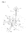
- FIG. 1 is a perspective view of a floating-body type wind turbine power generating apparatus according to one embodiment.
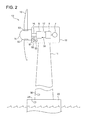
- FIG. 2 is a schematic diagram of a configuration of a floating-body type wind turbine power generating apparatus according to one embodiment.
- the floating-body type wind turbine power generating apparatus 1 includes a floating body 20 floating on the water surface and a wind turbine generator 10 erected on the floating body 20. Further, the floating-body type wind turbine power generating apparatus 1 includes a control unit 50 and a monitoring unit 30 described below.
- the floating body 20 is moored so as to be fixed to the water bottom by mooring devices 26 (26a to 26h).
- the floating body 20 includes three columns 22 (22a to 22c), the first lower hull 24a connecting the column 22a and the column 22b, and the second lower hull 24b connecting the column 22a and the column 22c.
- the floating body 20 is formed in a substantially V shape.
- the columns 22 and the lower hulls 24 are each formed to have a hollow structure so that the floating-body type wind turbine power generating apparatus 1 floats on the water surface due to the buoyance applied to the columns 22 and the lower hulls 24.
- the upper surfaces 22u of the columns 22 are formed so as to be disposed above the upper surfaces 24u of the lower hulls 24, and the upper surfaces 24u of the lower hulls 24 are underwater and the upper surfaces 22u of the columns 22 are above the water surface while the floating-body wind turbine power generating apparatus is in an installed state. That is, the floating body 20 is a semi-submersible type floating body. Further, a wind turbine generator 10 is disposed on the column 22a positioned at the center among the above three columns 22.
- the wind turbine generator 10 standing on the floating body 20 includes a tower 11 fixed on the column 22a, a nacelle 12 supported to the tower, and a rotor 13 mounted to the nacelle 12 rotatably.
- the rotor 13 includes a hub 14 mounted to the nacelle 12 rotatably and blades 15 mounted to the hub 14.
- the nacelle 12 is supported by the tower 11 so as to be capable of slewing (capable of rotating in the yaw direction) about an axis of the tower 11, and configured to orient the rotor 13 toward the upwind side in accordance with the wind direction.
- FIG. 2 is a schematic diagram of a configuration of a floating-body type wind turbine power generating apparatus according to one embodiment.
- a hydraulic pump 5 is coupled to the rotor 13 via the main shaft 16.
- a hydraulic motor 6 is connected to the hydraulic pump 5 via a high pressure oil line 17 and a low pressure oil line 18.
- the outlet of the hydraulic pump 5 is connected to the inlet of the hydraulic motor 6 via the high pressure oil line 17, while the inlet of the hydraulic pump 5 is connected to the outlet of the hydraulic motor 6 via the low pressure oil line 18.
- the hydraulic pump 5 increases the pressure of working oil by being driven by a main shaft 16 so as to produce high pressure working oil (pressurized oil).
- the pressurized oil produced by the hydraulic pump 5 is supplied to the hydraulic motor 6 via the high pressure oil line 17, and this pressurized oil drives the hydraulic motor 6.
- the low pressure working oil having performed work in the hydraulic motor 6 is returned again to the hydraulic pump 5 via the low pressure oil line 18 disposed between the outlet of the hydraulic motor 6 and the inlet of the hydraulic pump 5.
- a generator 7 is coupled to the hydraulic motor 6.
- the generator 7 is to convert rotation energy of the rotor 4 into electric energy.
- the generator 7 is a synchronous generator driven by the hydraulic motor 6, and is connected to a utility grid without an electric-power converting circuit including an inverter being disposed therebetween.
- the wind turbine generator 10 described here as one embodiment transmits the rotation energy of the rotor 13 to the generator 7 through a hydraulic transmission including the hydraulic pump 5 and the hydraulic motor 6, the wind turbine generator 10 may be configured to increase the rotation speed of the rotor 13 with a gear-type speed increasing unit and transmit the rotation to the generator 7 in another embodiment. Further, in yet another embodiment, the wind turbine generator 10 may be a direct-drive type wind turbine generator which drives the generator 7 by rotation of the rotor 13 without a drivetrain interposed therebetween.
- the floating-body type wind turbine power generating apparatus 1 includes a control unit 50 for controlling pitch angles of the blades 15 and a monitoring unit 30 for monitoring vibration of the floating body 20.
- the floating-body type wind turbine power generating apparatus 1 includes a rotation speed meter 51 for measuring the rotation speed of the rotor 13 inside the nacelle, and a pitch-angle adjustment mechanism 53 for adjusting pitch angles of the blades 15 inside the hub.
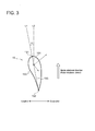
- each blade 15 has an airfoil in which a pressure surface 153 and a suction surface 154 extend from a leading edge 151 to a trailing edge 152.
- the straight line 155 connecting the leading edge 151 and the trailing edge 152 is referred to as a chord.
- a pitch angle of the blade is an angle between an extension line L 1 of the chord 155 and a straight line L 2 parallel to the blade rotational direction (the rotor rotational plane). In FIG. 3 , the pitch angle is the angle ⁇ .
- Each blade 15 typically has a pitch angle of approximately 0 degree while the wind turbine generator 10 is in normal operation, and the pitch angle here is referred to as a fine position.
- each blade 2 typically has a pitch angle of approximately 90 degrees (the maximum angle) while the wind turbine generator 10 is completely stopped, and the pitch angle here is referred to as a feather position.
- the pitch angle of each blade 15 is increased from the fine position (approx. 0 degree) toward the feather position (approx.
- the control unit 50 is capable of executing a control mode in which the pitch angles of the blades 15 are controlled so as to maintain the rotation speed of the rotor 13 at a rated rotation speed.
- This control mode is also referred to as "pitch-angle control mode" hereinafter.
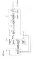
- the pitch angle of each blade 15 which is be achieved by the control is calculated by a pitch-angle control part 54 on the basis of the rotation speed of the rotor 13 measured by the rotation speed meter 51 or the like (see FIG. 4 ).
- the pitch-angle adjustment mechanism 53 adjusts the pitch angles of the blades 15 on the basis of the calculated pitch command angle.
- sway of the floating-body type wind turbine power generating apparatus 1 may be promoted in accordance with the control of the pitch angles. Further, due to such promotion of the sway, self-excited vibration having a natural period of the sway of the floating body may be generated on the floating body 20.
- the monitoring unit 30 is provided to monitor vibration of the above floating body 20.
- the monitoring unit 30 is configured to detect abnormal vibration due to execution of the pitch-angle control mode by the control unit 50, on the basis of the statistic value in a period of not less than the floating-body sway natural period of the floating body 20.
- the statistical value is obtained using the fluctuation amount of a value obtained from a signal representing at least one of the inclination angle or the inclination-angular velocity of the floating body 20.
- the statistical value based on the inclination angle or the inclination-angular velocity of the floating body 20 upon floating-body sway caused by the pitch control represents a fluctuation component of the inclination angle or the inclination-angular velocity of the floating body 20 generated upon floating-body sway due to the pitch control.
- it is possible to detect abnormal vibration of the floating body caused by the pitch control by using the statistical value representing a fluctuation component of the inclination angle or the inclination-angular velocity of the floating body 20 which affects the stress amplitude generated in the wind turbine generator.
- the floating-body type wind turbine power generating apparatus 1 includes an inclinometer 28 as a sensor for measuring a physical amount which represents at least one of the inclination angle or the inclination-angular velocity of the floating body 20.
- the inclinometer 28 is a gyroscope.
- the inclinometer 28 is disposed on the floating body 20.
- the inclinometer 28 may be disposed on a base part of the tower 11.
- the floating-body wind turbine power generating apparatus 1 may include an acceleration sensor 52 as a sensor for measuring a physical amount which represents at least one of the inclination angle or the inclination-angular velocity of the floating body 20.
- the acceleration sensor 52 may be disposed on the nacelle 12 of the wind turbine generator 10 as illustrated in FIG. 2 .
- the sensor including the inclinometer 28 is configured to measure a physical amount representing at least one of the inclination angle or the inclination-angular velocity of the floating body 20 at a predetermined sampling period S (for instance, 20Hz).
- the monitoring unit 30 is configured to detect abnormal vibration due to execution of the pitch angle control mode by the control unit 50, on the basis of the statistical value based on a difference between the value obtained from the signal representing at least one of the inclination angle or the inclination-angular velocity of the floating body 20 and the mean value of the value in a period of not less than the floating-body sway natural period of the floating body.
- Fig .4 is a block diagram of a configuration of a wind turbine generator, a floating body, a control unit and a monitoring unit according to one embodiment.
- the monitoring unit 30 includes a signal-obtaining part 32, a mean-value calculation part 36, a statistical-value calculation part 38, and a comparison part 40.
- the monitoring unit 30 may include a filter (the second filter) 34.
- the inclinometer 28 for measuring a physical amount representing the inclination angle of the floating body 20 is employed as a sensor for measuring a physical amount representing at least one of the inclination angle or the inclination-angular velocity of the floating body 20 is employed.
- abnormal vibration of the floating body 20 is detected using the fluctuation amount of a value obtained from a signal representing the inclination angle of the floating body 20.
- similar description applies to a case where abnormal vibration of the floating body 20 is detected using a fluctuation amount of a value obtained from a signal representing the inclination-angular velocity of the floating body 20.
- the signal-obtaining part 32 is configured to obtain a signal representing the inclination angle of the floating body 20, on the basis of a detection signal which represents a physical amount representing the inclination angle of the floating body 20 from the inclinometer 28.
- the signal-obtaining part 32 is configured to obtain a signal representing the inclination angle of the floating body 20 on the basis of the above detection signal.
- the mean-value calculation part 36 calculates a mean value "m" over a predetermined statistical period T[s] from the following equation (B) for a value xi obtained from a signal representing the inclination angle of the floating body 20 obtained by the signal-obtaining part 32.
- x i is a value representing the inclination angle of the floating body 20
- N is the number of data x i in the statistical period T[s].
- the statistical value calculation part 38 calculates the fluctuation amount xa i of the inclination angle x i of the floating body 20 from the following equation (C) using the mean value m calculated by the mean-value calculation part 36, and further calculates a statistical value ⁇ over the statistical period T from the following equation (A).
- n is an optional number.
- the statistical value ⁇ represents dispersion of the inclination angle of the floating body 20 over the statistical period T.
- the magnitude of dispersion of the inclination angle of the floating body 20 corresponds to the magnitude of dispersion of a load applied to the wind turbine generator 10 due to the inclination angle or the like of the floating body 20, and of stress generated in accordance with the load.
- represents the amplitude of the floating-body sway.
- the statistical value ⁇ calculated form the above equation (A) represents dispersion of the amplitude of the floating-body sway of the floating body 20 over the statistical period T.
- n 2.
- the statistical value ⁇ represents a standard deviation of the inclination angle of the floating body 20.
- n in the above equation (A) may be a number which is a product of an inverse of the slope of an S-N curve at a location receiving a fatigue load and minus 1. For instance, in a case where a fatigue load applied to the tower base part is considered, if the slope of the S-N curve of the steel material of the tower is minus 1/4, n may be 4.
- the statistical value ⁇ over the statistical period T is calculated using the mean value m over the statistical period T calculated by the mean value calculation part 36.
- the statistical period T is a period of not less than the floating-body sway natural period of the floating body 20. If the statistical period T is at least as long as the floating-body sway natural period of the floating body 20, it is possible to calculate an appropriate mean value m for calculating the statistical value ⁇ , using the data of the inclination angle obtained during a single period of the floating-body sway natural period.
- the floating-body sway natural period may be 20 to 30 seconds, depending on the floating body or the type of the floating body.
- the statistical period T for calculating the statistical value ⁇ related to the inclination angle of the floating body 20 is too short, the number of samples in the statistical period T would be so few that the statistical value ⁇ to be calculated is affected and that appropriate evaluation is not possible. For instance, in a case where " ⁇ " represented by the above equation (A) is used as the statistical value ⁇ , the smaller number of the samples may result in a larger value, which makes it necessary to increase the threshold value.
- the statistical period T may be not less than five times as long as the floating-body sway natural period, or not less than 150 seconds. In this way, it is possible to secure an adequate number of samples for calculating the statistical value ⁇ over the statistical period T, and to detect abnormal vibration of the floating body 20 due to the pitch control more appropriately. Further, since the statistical period T is adequately long, it is possible to avoid detection of a sudden external-force response such as a wave response, which makes it possible to monitor continuous unstable vibration which causes an increase in a fatigue load applied to the wind turbine generator 10 appropriately.
- the statistical period T for calculating the statistical value ⁇ related to the inclination angle of the floating body 20 is too long, when the wind condition radically changes in the statistical period T, appropriate evaluation may be impossible due to the calculated statistical value ⁇ being affected by the radical change in the wind condition. For instance, assuming that there is a period during which the wind velocity or the wave height is low and the inclination angle of the floating body 20 is substantially zero in a statistical period T, values would be averaged over the entire period to calculate the mean value of the inclination angle, including the period with the inclination angle being zero. Thus, even if there is a time when the wind velocity or the wave height has rapidly increased in the other periods, it may be difficult to determine the influence of the rapid increase.
- the statistical period T may be not more than 10,800 seconds or not more than 3,600 seconds in one embodiment. In this case, it is possible to detect abnormal vibration of the floating body 20 caused by the pitch control more appropriately, taking account of a change in the wind condition in the statistical period T.
- the monitoring unit 30 may calculate the statistical value ⁇ on the basis of the fluctuation amount obtained by a method different from the above.
- the monitoring unit 30 may include the first filter (not illustrated) for eliminating or reducing a component of a period longer than the floating-body sway natural period of the floating body 20 from a signal representing the inclination angle of the floating body 20 instead of the above mean-value calculation part 36, and may be configured to calculate a statistical value over the statistical period T using the fluctuation amount based on the value obtained from the signal processed by the first filter and detect abnormal vibration of the floating body 20 on the basis of this statistical value.
- the first filter makes it possible to eliminate, from the signal representing the inclination angle of the floating body 20 obtained by the inclinometer 28, a drift component of the signal or a low-frequency response component such as a natural frequency due to the mooring device 26 (mooring cables) and the floating body 20. Further, using the first filter makes it possible to eliminate, from the signal representing the inclination angle of the floating body 20, a component which has a frequency of zero and does not change with time. In this way, it is possible to obtain a waveform which has the floating-body sway natural period of the floating body 20 and has a mean of substantially zero, so that the value representing the amplitude of the floating-body sway can be directly obtained from the signal representing the inclination angle of the floating body 20. Then, from the fluctuation amount of the value representing the amplitude over the statistical period T, it is possible to detect abnormal vibration of the floating body 20.
- a filter capable of reducing or eliminating a component of a period longer than the natural frequency (for instance, 0.03 to 0.05Hz) of sway of the floating body 20, which is a component with a small frequency, can be used.
- a high-pass filter having a cutoff frequency of 0.02Hz is used, for instance.
- the first filter is used instead of the mean-value calculation part 36, it is possible to calculate the statistical value ⁇ over the statistical period T by the above equation (A) from the value xa i representing the fluctuation amount of the inclination angle, which is the value representing the amplitude of the floating-body sway, obtained from the signal processed by the first filter.
- the value xa i representing the fluctuation amount of the inclination angle
- the value representing the amplitude of the floating-body sway obtained from the signal processed by the first filter.
- the comparison part 40 compares the statistical value ⁇ calculated by the statistical value calculation part 38 with the threshold value ⁇ TH having been set in advance. If the calculated statistical value ⁇ is greater than the threshold value ⁇ TH as a result of the comparison, it is determined that abnormal vibration has occurred to the floating body 20.
- the monitoring unit 30 outputs an alarm when abnormal vibration of the floating body 20 is detected in the comparison part 40. Outputting an alarm upon detection of abnormal vibration of the floating body 20 makes it possible to take a measure after detection of abnormal vibration, such as procedures for stopping the wind turbine generator 10 performed by workers who recognized detection of the abnormal vibration from the alarm.
- the monitoring unit 30 transmits a signal for stopping the wind turbine generator 10 to the control unit 50 when abnormal vibration of the floating body 20 is detected by the comparison part 40. Transmitting a signal for stopping the wind turbine generator 10 to the control unit 50 when abnormal vibration of the floating body 20 is detected by the comparison part 40 makes it possible to stop the wind turbine generator 10 immediately by the control unit 50.
- the threshold value ⁇ TH to be compared with the calculated statistical value ⁇ is set to be within a range of not less than 0.5 degree and not more than 5 degrees.
- the influence of self-exciting vibration on the floating-body sway is relatively small.
- the influence is smaller than that of the ocean waves.
- the threshold value ⁇ TH for a semi-submersible type floating-body may be in a range of from 0.5 degree to 3 degrees.
- the floating body is of a spar type having a cylindrical shape
- the influence of self-exciting vibration on the floating-body sway is relatively large, and the floating body has a structure in which tilting is likely to appear due to self-exciting vibration.
- the threshold value ⁇ TH of a spar type floating-body may be in a range of from 3 to 5 degrees.
- the monitoring unit 30 may be configured such that the threshold value ⁇ TH , which is to be compared with the statistical value ⁇ calculated by the statistical value calculation part 38, is variable in accordance with the mean value of the pitch angle the wind velocity of wind received by the rotor 13 in the statistical period T.
- the pitch angle of the blade 15 controlled by the pitch angle control part 54 may depend on the wind velocity received by the rotor 13.
- the wind velocity received by the above rotor 13 may be an actual measurement value measured by an anemometer (not illustrated) disposed on the wind turbine generator 10, or an estimate value estimated on the basis of the pitch angle of the blade, the rotation speed of the rotor 13, the torque of the rotor 13, or the like.
- the above pitch angle may be an actual measurement value or a pitch command angle calculated by the pitch angle control part 54 while the pitch angle control mode is executed.
- FIG. 5 is a diagram of a change in the threshold value of the statistical value with respect to the mean value of wind velocity according to one embodiment.
- the threshold value ⁇ TH to be compared with the statistical value ⁇ calculated by the statistical value calculation part 38 is set so as to reach the maximum at a wind velocity V 1 not less than the rated wind velocity, and to decrease with an increase in the wind velocity, in a region in which the mean value of the wind velocity received by the rotor 13 is not less than the rate wind velocity of the wind turbine generator 10.
- the floating-body sway due to the pitch control occurs when the pitch angle control mode is executed, i.e., when the wind velocity is the rated wind velocity or higher. Further, there is a tendency that the floating-body sway due to the pitch control is the most likely to occur at the rated wind velocity, and is less likely to occur as the wind velocity increases in a high wind-velocity region where the wind velocity is the rated wind velocity or higher. Thus, the higher the wind velocity is, the more it is desirable to detect abnormal sway of the floating body with high sensitivity.
- the threshold value ⁇ TH in a region where the mean value of the wind velocity of wind received by the rotor 13 is not less than the rated wind velocity is set so as to reach the maximum ( ⁇ TH _ Max ) at a wind velocity V 1 which is not less than the rated wind velocity, and to decrease with an increase in the wind velocity, which makes it possible to detect abnormal vibration with sensitivity that increases with the mean value of the wind velocity of wind received by the rotor 13.
- V 1 which is not less than the rated wind velocity
- the threshold value is set so as to reach the maximum when the mean value of the wind velocity of wind received by the rotor 13 is the rated wind velocity.
- the threshold value is set so as to reach the maximum in a range where the mean value of the wind velocity of wind received by the rotor 13 is not less than (rated wind velocity + 1) m/s, and not more than (rated wind velocity + 3) m/s. In a wind velocity region where the wind velocity is less than the rated wind velocity and the pitch angle control mode is not executed, the floating-body sway due to the pitch control does not occur.
- the ⁇ TH in a case where the mean of the wind velocity over the statistical period T is a little greater than the rated wind velocity (for instance, 1 to 3 m/s) is set at the maximum ⁇ TH_Max
- the ⁇ TH in a case where the mean of the wind velocity is the rated wind velocity is set at a value smaller than ⁇ TH_Max (for instance, ⁇ TH_Rated in FIG. 5 ) taking account of a case where the wind velocity is less than the rated wind velocity, which makes it possible to detect abnormal vibration of the floating body 20 more appropriately.
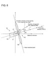
- FIG. 6 is a diagram for describing the front-rear direction and the yaw angle of the wind turbine generator.
- the monitoring unit 30 is configured to detect abnormal vibration due to execution of the pitch angle control mode by the control unit 50, on the basis of a statistical value based on a difference between a value obtained from a signal representing the inclination angle or the inclination-angular velocity of the floating body 20 in the front-rear direction of the wind turbine generator 10 and a mean value of the value over a period of not less than the floating-body sway natural period of the floating body 20.
- the pitch control mainly promotes the sway in the front-rear direction (a direction orthogonal to the rotational plane of the rotor 13 of the wind turbine generator 10; see FIG. 6 ) of the wind turbine generator 10.
- evaluation is performed on the basis of the inclination angle or the inclination-angular velocity of the floating body 20 in the front-rear direction of the wind turbine generator 10, which makes it possible to detect abnormal vibration of the floating body 20 due to the pitch control more precisely.
- the monitoring unit 30 may be configured to detect the above abnormal vibration on the basis of a statistical value based on a difference between: a value obtained from the signal representing the inclination angle or the inclination-angular velocity of the floating body 20 at an angle offset by several degrees with respect to the vertical axis O of the tower 11 from the front-rear direction of the wind turbine generator 10 (for instance, an angle in a range of from minus 30 to plus 30 degrees); and a mean value of the value over a period of not less than the floating-body sway natural period of the floating body 20.
- the monitoring unit 30 may be configured to detect abnormal vibration due to execution of the pitch angle control mode by the control unit 50, on the basis of a statistical value based on a difference between: a value obtained from a signal representing the inclination angle or the inclination-angular velocity of the floating body 20 in the front-rear direction and a direction orthogonal to the front-rear direction of the wind turbine generator 10 (for instance, a composition of a signal representing the inclination angle or the like in the front-rear direction of the wind turbine generator 10 and a signal representing the inclination angle or the like in the orthogonal direction of the wind turbine generator 10); and a mean value of the value in a period of not less than the floating-body sway natural period of the floating body 20.
- a statistical value based on a difference between: a value obtained from a signal representing the inclination angle or the inclination-angular velocity of the floating body 20 in the front-rear direction and a direction orthogonal to the front-rear direction of the wind turbine
- the signal-obtaining part 32 may be configured to calculate an angular difference ⁇ in a top view between the front-rear direction of the wind turbine generator 10 and a tilting direction in which the inclinometer 28 performs measurement based on a yaw angle ⁇ z of the wind turbine generator 10 and obtain the signal in the front-rear direction of the wind turbine generator 10 from the detection signal of the inclinometer 28 on the basis of the angular difference ⁇ .
- the yaw angle refers to an angle ⁇ z between a direction orthogonal to the rotational plane of the rotor 13 (which is the front-rear direction of the wind turbine generator 10) and a reference direction which is a direction into which a predetermined position of the tower 11 is oriented with respect to the perpendicular axis O of the tower 11 being the center.
- the signal obtaining part 32 is configured to obtain a detection signal by the inclinometer 28 of the time when the above angular difference ⁇ is zero, as a signal in the front-rear direction of the wind turbine generator 10.
- the acceleration meter 52 disposed on the nacelle 12 is used as a sensor for measuring a physical amount representing at least one of the inclination angle or the inclination-angular velocity of the floating body 20
- the acceleration meter 52 may be configured to obtain an acceleration of the nacelle 12 in the front-rear direction of the wind turbine generator 10.
- the signal obtaining part 32 may be configured to convert a signal representing an acceleration of the nacelle 12 obtained by the acceleration meter 52 into a signal representing the inclination angle of the floating body 20 by processing the signal representing the acceleration. More specifically, for instance, a moving velocity v of the nacelle 12 in the front-rear direction of the wind turbine generator 10 is calculated by integrating an acceleration of the nacelle 12 in the front-rear direction of the wind turbine generator 10 obtained by the acceleration meter 52.
- the length to the nacelle 12 from the gravity center of the floating-body type wind turbine power generating apparatus 1 being the rotational center of the floating body 20 is h
- the angular velocity ⁇ of the nacelle 12 is v/h.
- the length here is the length to the acceleration meter 52 from the gravity center of the floating-type wind turbine power generating apparatus 1.
- the monitoring unit 30 may further include the second filter 34 for eliminating or reducing at least a frequency component of waves which acts on the floating body 20 from the signal representing the inclination angle of the floating body 20.
- the monitoring unit 30 may be configured to detect abnormal vibration of the floating body 20 by calculating the above mean value m and the statistical value ⁇ by the mean value calculation part 36 and the statistical value calculation part 38 on the basis of the statistical value based on the signal processed by the second filter 34.
- evaluation is performed on the basis of the signal obtained by eliminating or reducing a frequency component of waves from the signal representing the inclination angle.
- the frequency component of waves is a great obstacle in evaluation of the floating-body sway.
- it is possible to detect abnormal vibration of the floating body due to the pitch control more precisely.
- a frequency of waves is higher (e.g. 0.05 to 0.2Hz) than the natural frequency of sway of the floating body 20 (e.g. 0.03 to 0.05Hz).
- a low-pass filter having a cutoff frequency of 0.1Hz may be used as the second filter 34 to reduce or eliminate frequency components of 0.1 Hz and more.
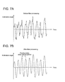
- FIG. 7A is an example of a waveform of a signal representing the inclination angle
- FIG. 7B is a diagram of a waveform according to one embodiment after the waveform of FIG. 7A has been processed by the second filter (the above low-pass filter).
- the second filter the above low-pass filter
- processing the signal representing the inclination angle of the floating body 20 by the second filter makes it possible to eliminate noise having a component of a period shorter than the floating-body sway natural period such as a wave period.
- the second filter 34 may be configured to reduce or eliminate a component of natural frequency related to a structure (e.g. tower 11) other than the floating body 20, included in the floating-body type wind turbine power generating apparatus 1.
- the monitoring unit 30 detects abnormal vibration of the floating body 20 on the basis of the statistical value ⁇ only when the wind velocity of wind received by the rotor 13 is not less than the rated wind velocity or only when the pitch control mode is executed by the control unit 50.
- Whether the pitch angle control mode is being executed by the control unit 50 may be determined by determining whether the pitch command value calculated by the pitch angle control part 54 is not less than a threshold value, or by determining whether the mean value of the pitch angles of a plurality of blades 15 is not less than a threshold value.
- the monitoring unit 30 may be configured to detect abnormal vibration of the floating body 20 on the basis of the statistical value ⁇ only when the mean value of the wind velocity of wind received by the rotor 13 over the statistical period T is not less than the rated wind velocity.
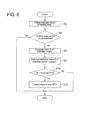
- FIG. 8 is a flowchart of a method of operating a floating-body type wind turbine power generating apparatus according to one embodiment.
- the floating-body type wind turbine power generating apparatus 1 according to the above described embodiment can be operated according to the operation method illustrated in FIG. 8 .
- the pitch angle control mode is being executed (S4).
- the pitch angle of the blade 15 is controlled so as to maintain the rotation speed of the rotor 13 at the rated rotation speed.
- the mean value m over a period of not less than the floating-body sway natural period of the floating body 20, which is the statistical period T, is calculated for the inclination angle obtained in S2 (S6).
- the mean value m can be calculated by the above equation (B), for instance.
- a statistical value ⁇ is calculated using a difference between the inclination angle of the floating body 20 obtained from the signal obtained in S2 and the mean value m of the inclination angle of the floating body 20 over the statistical period T obtained in S6 (S8).
- the statistical value ⁇ can be calculated from, for instance, the above equation (A).
- the statistical value ⁇ calculated in S8 is compared to a threshold value ⁇ TH having been set in advance (S10).
- an expression of relative or absolute arrangement such as “in a direction”, “along a direction”, “parallel”, “orthogonal”, “centered”, “concentric” and “coaxial” shall not be construed as indicating only the arrangement in a strict literal sense, but also includes a state where the arrangement is relatively displaced by a tolerance, or by an angle or a distance whereby it is possible to achieve the same function.
- an expression of an equal state such as “same” “equal” and “uniform” shall not be construed as indicating only the state in which the feature is strictly equal, but also includes a state in which there is a tolerance or a difference that can still achieve the same function.
- an expression of a shape such as a rectangular shape or a cylindrical shape shall not be construed as only the geometrically strict shape, but also includes a shape with unevenness or chamfered corners within the range in which the same effect can be achieved.
Abstract
Figure 2
Description
- The present disclosure relates to a floating-body type wind turbine power generating apparatus and an operation method of the same.
- When a wind turbine power generating apparatus is placed on the ocean, for instance, a bottom-mounted wind turbine power generating apparatus is generally employed in a region where the water is not so deep. A bottom-mounted wind turbine power generating apparatus is disposed on a base installed on the water bottom. In contrast, in a region with a great water depth, such a bottom-mounted wind turbine power generating apparatus is not economic, and thus one would consider employing a floating-body type wind turbine power generating apparatus in which a wind turbine generator is disposed on a floating body floating on the water surface.
-
Patent Document 1 discloses a floating-body type wind turbine power generating apparatus including a pitch controller for controlling pitch angles of blades mounted to a wind turbine rotor. In this floating-body type wind turbine power generating apparatus, the pitch controller controls the pitch angles on the basis of the rotation speed of the wind turbine rotor. For instance, during operation at a wind velocity less than a rated wind velocity, the pitch angles are maintained substantially constant at an angle such that the maximum electric power is supplied. On the other hand, during operation at a rated wind velocity or higher, the pitch angles of the blades are controlled so as to maintain a constant rotor rotation speed (rated rotor rotation speed) to generate a constant generator output (a rated output). -
- Patent Document 1:
WO2010/076557A - In a floating-body type wind turbine power generating apparatus, there is a close correlation between sway of a floating body and an aerodynamic load (thrust force) of a thrust component received by a rotor. Thus, the following phenomenon may occur when a mode in which pitch angles of blades are controlled so as to maintain the rotation speed of a rotor at a rated rotation speed is executed for the floating-body type wind turbine power generating apparatus.
- If the wind velocity relative to the rotor increases in accordance with the movement (inclination) of the wind turbine generator toward the upwind side due to sway of the floating body while the mode in which the pitch angles of the blades are controlled so as to maintain the rotation speed of the rotor at a rated rotation speed is executed, the pitch angles of the blades would be controlled to increase so as to maintain the rotor rotation speed of the rotor at a rated rotation speed. If the pitch angles of the blades are increased while the wind turbine generator is moving toward the upwind side, the movement of the wind turbine generator toward the upwind side would be enhanced because the thrust force received by the rotor from wind decreases, causing the wind turbine generator to incline greatly toward the upwind side.
- In contrast, if the wind velocity relative to the rotor decreases in accordance with the movement (inclination) of the wind turbine generator toward the downwind side due to sway of the floating body while the mode in which the pitch angles of the blades are controlled so as to maintain the rotation speed of the rotor at a rated rotation speed is executed, the pitch angles of the blades would be controlled to decrease so as to maintain the rotor rotation speed of the rotor at a rated rotation speed. If the pitch angles of the blades are reduced while the wind turbine generator is moving toward the downwind side, the movement of the wind turbine generator toward the downwind side would be enhanced because the thrust force received by the rotor from wind increases, causing the wind turbine generator to incline greatly toward the downwind side.
- As described above, if a floating-body type wind turbine power generating apparatus sways while the mode in which the pitch angles of the blades are controlled so as to maintain the rotation speed of the rotor at a rated rotation speed is executed, the sway of the floating-body type wind turbine power generating apparatus may be promoted in accordance with the control of the pitch angles. Due to the promotion (aerodynamic negative damping) of the sway of the floating-body type wind turbine power generating apparatus caused by such pitch control, self-excited vibration having a floating-body sway natural period may be generated in the floating body. In this case, a cyclic load is applied to the wind turbine generator in accordance with the cyclic sway of the floating body caused by the self-excited vibration. Thus, depending on the amplitude of the sway of the floating body or its elapsed time, a fatigue load larger than a setting value may be applied to the wind turbine generator, which may result in excess over a fatigue limit of the wind turbine generator.
- To prevent damage to the wind turbine generator due to such a fatigue load, it is desirable to detect abnormal sway of the floating body, which is abnormal vibration, appropriately by monitoring the sway of the floating body caused by the pitch control.
- In this regard,
Patent Document 1 describes no measure for detecting abnormal vibration of a floating body caused by the pitch control. - In view of the above issues, an object of at least one embodiment of the present invention is to provide a floating-body type wind turbine power generating apparatus whereby it is possible to detect abnormal vibration of a floating body caused by a pitch control appropriately.
- (1) A floating-body type wind turbine power generating apparatus according to at least one embodiment of the present invention includes: a floating body; a wind turbine generator erected on the floating body, the wind turbine generator including a rotor having a hub and a blade mounted to the hub; a control unit capable of executing a control mode in which a pitch angle of the blade is controlled so that a rotation speed of the rotor is maintained at a rated rotation speed; and a monitoring unit for monitoring vibration of the floating body.
- The monitoring unit is configured to detect abnormal vibration due to execution of the control mode by the control unit, on the basis of a statistical value over a period of not less than a floating-body sway natural period of the floating body, the statistical value being based on a fluctuation amount of a value obtained from a signal representing at least one of an inclination angle or an inclination-angular velocity of the floating body.
- When a floating body and a wind turbine generator disposed on the floating body are inclined, a load corresponding to the inclination angle, the inclination-angular velocity or the like of the floating body is applied to the wind turbine generator. For instance, a load due to the moment of the self weight depends on the inclination angle of the floating body. Further, since the inclination-angular velocity of the floating body affects the relative wind velocity received by the rotor, the wind load received by the rotor depends on the inclination-angular velocity of the floating body. Stress is generated in response to the above loads in a wind turbine generator, and thus the stress in a wind turbine generator varies in accordance with the change in the inclination angle, the inclination-angular velocity or the like of the floating body. Thus, the magnitude of the stress amplitude which affects the fatigue strength of the wind turbine generator is correlated to the fluctuation component of the inclination angle, the inclination-angular velocity, or the like of the floating body in the floating-body sway caused by the pitch control.
- With the above configuration (1), abnormal vibration of the floating body is detected using a statistical value based on fluctuation amount of the inclination angle or the inclination-angular velocity of the floating body in floating-body sway caused by the pitch control. This statistical value represents a fluctuation component of the inclination angle or the inclination-angular velocity of the floating body in floating-body sway caused by the pitch control. Thus, it is possible to detect abnormal vibration of the floating body caused by the pitch control appropriately by using the above statistical value based on a fluctuation component of the inclination angle or the inclination-angular velocity which may affect the stress amplitude generated in the wind turbine generator.
- (2) In some embodiments, in the above configuration (1), the fluctuation amount is obtained from a difference between the value and a mean of the value over the period. Specifically, in some embodiments, the monitoring unit is configured to detect the abnormal vibration on the basis of a statistical value based on the fluctuation amount based on a difference between the value obtained from the signal and a mean value of the value over the period.
- In the above configuration (2), to detect abnormal vibration of the floating body, the statistical value being used is based on a difference between the inclination angle or the inclination-angular velocity of the floating body in the floating-body sway caused by the pitch control, and a mean value of the inclination angle or the inclination-angular velocity. This statistical value represents a fluctuation component of the inclination angle or the inclination-angular velocity of the floating body in the floating-body sway caused by the pitch control. Thus, it is possible to detect abnormal vibration of the floating body caused by the pitch control appropriately by using the above statistical value representing a fluctuation component of the inclination angle or the inclination-angular velocity which may affect the stress amplitude generated in the wind turbine generator.
- (3) In some embodiments, in the above configuration (1), the monitoring unit includes a first filter for eliminating or reducing a component of a period longer than the floating-body sway natural period of the floating-body from the signal. The fluctuation amount is obtained by processing the value with the first filter. Specifically, in some embodiments, the monitoring unit is configured to detect the abnormal vibration on the basis of the statistical value based on the fluctuation amount based on the value obtained from the signal processed by the first filter.
- With the above configuration (3), to detect abnormal vibration of the floating body, the statistical value being used is obtained using a fluctuation amount based on a signal obtained by eliminating or reducing a component of a period longer than the floating-body sway natural period of the floating-body from the signal representing the inclination angle or the inclination-angular velocity of the floating body in the floating-body sway caused by the pitch control. This statistical value represents a fluctuation component of the inclination angle or the inclination-angular velocity of the floating body in the floating-body sway caused by the pitch control. Thus, it is possible to detect abnormal vibration of the floating body caused by the pitch control appropriately by using the above statistical value representing a fluctuation component of the inclination angle or the inclination-angular velocity which may affect the stress amplitude generated in the wind turbine generator.
- (4) In some embodiments, in any one of the above configurations (1) to (3), the monitoring unit is configured to detect the abnormal vibration due to execution of the control mode by the control unit, on the basis of a statistical value in a period of not less than a floating-body sway natural period of the floating body, the statistical value being based on a fluctuation amount of a value obtained from a signal representing at least one of the inclination angle or the inclination-angular velocity of the floating body in a front-rear direction of the wind turbine generator.
- While a floating-body type wind turbine generator may sway in various directions, the pitch control mainly promotes the sway in the front-rear direction of the wind turbine generator.
- With the above configuration (4), evaluation is performed on the basis of the inclination angle or the inclination-angular velocity of the floating body in the front-rear direction of the wind turbine generator, which makes it possible to detect abnormal vibration of the floating body due to the pitch control more precisely.
- In the present specification, "the front-rear direction of the wind turbine generator" refers to a direction orthogonal to the rotational plane of the rotor of the wind turbine generator. The expression "the front-rear direction" refers to the same in other parts of the specification as well unless otherwise noted.
- (5) In some embodiments, in any one of the above configurations (1) to (4), the statistical value is "σ" represented by the following equation (A).

- In equation (A), xai is the fluctuation amount of the value representing the inclination angle or the inclination-angular velocity of the floating body, and N is the number of data of xai in the period.
- In the above configuration (5), a statistical value representing dispersion of the inclination angle or the inclination-angular velocity of the floating body is used as the statistical value based on the fluctuation amount of the inclination angle or the inclination-angular velocity of the floating-body. The magnitude of dispersion of the inclination angle or the like corresponds to the magnitude of dispersion of a load applied to the wind turbine due to the inclination angle or the like, and of stress caused in accordance with the load. Thus, the greater the dispersion of the inclination angle or the like is, the greater the stress amplitude of the stress generated in the wind turbine generator would be.
- Accordingly, with the above configuration (5), it is possible to detect abnormal vibration of the floating body caused by the pitch control appropriately, using the statistical value representing dispersion of the inclination angle or the inclination-angular velocity.
- (6) In some embodiments, in any one of the above configurations (1) to (5), the length of the period is not less than 150 seconds and not more than 3,600 seconds.
- If a period for calculating the statistical value related to the inclination angle or the inclination-angular velocity of the floating body (hereinafter, also referred to as a statistical period) is too short, the number of samples in the statistical period may be so few that the statistical value to be calculated is affected and that appropriate evaluation is not possible. For instance, in a case where "σ" represented by the above equation (A) is used as the statistical value, the smaller number of the samples may result in a larger value, which makes it necessary to increase the threshold value.
- With the above configuration (6), the statistical period is not less than 150 seconds, which is an adequately long period of time. In this way, it is possible to secure a sufficient number of samples for calculating the statistical value over the statistical period, and to detect abnormal vibration of the floating body due to the pitch control more appropriately. Further, since the statistical period is adequately long, it is possible to avoid detection of a sudden external-force response such as a wave response, which makes it possible to appropriately monitor continuous unstable vibration which causes an increase of a fatigue load applied to the wind turbine generator.
- On the other hand, if the statistical period for calculating the statistical value related to the inclination angle or the inclination-angular velocity of the floating body is too long, when the wind condition radically changes in the statistical period, appropriate evaluation may be impossible due to the calculated statistical value being affected by the radical change in the wind condition. For instance, assuming that there is a period during which the wind velocity and the wave height are low and the inclination angle of the floating body is substantially zero in a statistical period, values would be averaged over the entire period to calculate the mean value of the inclination angle, including the period with the inclination angle being zero. Thus, even if there is a time when the wind velocity or the wave height has rapidly increased in the other periods, it may be difficult to determine the influence of the rapid increase.
- In this regard, with the above configuration (6), the statistical period is not more than 3,600 seconds, and thus it is possible to detect abnormal vibration of the floating body caused by the pitch control more appropriately, taking account of a change in the wind condition in the statistical period.
- (7) In some embodiments, in the above configuration (5) or (6), the monitoring unit is configured to determine that the abnormal vibration has occurred if the statistical value σ is greater than a threshold value, the statistical value being based on a difference between the value in the period and a value representing the inclination angle of the floating body. The threshold value is set to be within a range of not less than 0.5 degree and not more than 5 degrees.
- As a result of intensive researches of the present inventors, it was found that it is possible to determine occurrence of abnormal vibration accurately by using a value in the above range as a threshold value to be compared with the calculated statistical value σ. Thus, with the above configuration (7), it is possible to determine occurrence of abnormal vibration accurately.
- (8) In some embodiments, in the above configuration (7), the monitoring unit is configured such that the threshold value is variable in accordance with a mean value of the pitch angle or a wind velocity of wind received by the rotor over the period.
- There is a certain correlation between the magnitude of the floating-body sway due to the pitch control and the wind velocity.
- With the above configuration (8), a threshold value is variable in accordance with a mean value of the wind velocity. Thus, it is possible to improve the accuracy in detecting abnormal vibration of the floating body.
- (9) In some embodiments, in the above configuration (8), in a region where the mean value of the wind velocity is not less than a rated wind velocity of the wind turbine generator, the threshold value is set to be the maximum at a wind velocity V1 which is not less than the rated wind velocity and to decrease with an increase in the wind velocity.
- In a common wind turbine generator which is referred to as a variable-speed wind turbine, variable-speed operation is performed. In the variable-speed operation, the output is controlled and the rotor rotation speed is maintained at an optimum value in accordance with the wind velocity in a low wind-velocity region in which the wind velocity is less than the rated wind velocity, while the pitch angle is controlled so as to maintain the rotor rotation speed at a constant speed in a high wind-velocity region in which the wind velocity is the rated wind velocity or higher.
- The floating-body sway due to control of the rotor rotation speed through the pitch occurs upon execution of the control mode in which the rotor rotation speed is controlled through the pitch, i.e., when the wind velocity is not less than the rated wind velocity. Further, there is a tendency that the floating-body sway due to the pitch control is the most likely to occur at the rated wind velocity, and is less likely to occur as the wind velocity increases in a high wind-velocity region in which the wind velocity is not less than the rated wind velocity. Thus, the higher the wind velocity is, the more it is desirable to detect abnormal sway of the floating body with high sensitivity.
- With the above configuration (9), the threshold value in a region where the mean value of the wind velocity is not less than the rated wind velocity is set so as to reach the maximum at a wind velocity V1 which is not less than the rated wind velocity, and to decrease with an increase in the pitch angle or the wind velocity, which makes it possible to detect abnormal vibration with sensitivity that increases with the mean value of the wind velocity. Thus, it is possible to improve accuracy in detection of abnormal vibration of the floating body.
- (10) In some embodiments, in any one of the above configurations (1) to (9), the monitoring unit includes a second filter for eliminating or reducing at least a frequency component of a wave acting on the floating body from the signal, and is configured to detect the abnormal vibration on the basis of a statistical value based on the fluctuation amount based on a value obtained from the signal processed by the second filter.
- With the above configuration (10), evaluation is performed on the basis of the signal obtained by eliminating or reducing a frequency component of waves from the signal representing the inclination angle or the inclination-angular velocity. The frequency component of wave may become a serious obstacle in evaluation of the floating body. Thus, it is possible to detect abnormal vibration of the floating-body due to the pitch control more precisely.
- (11) In some embodiments, in any one of the above configurations (1) to (10), the floating-body type wind turbine power generating apparatus further includes: a sensor for measuring a physical amount representing at least one of the inclination angle or the inclination-angular velocity of the floating body; and a signal-obtaining part for obtaining the signal representing at least one of the inclination angle or the inclination-angular velocity of the floating body, on the basis of a detection signal from the sensor.
- In this case, it is possible to calculate the statistical value for detecting abnormal vibration of the floating body on the basis of the detection signal from the sensor for measuring the inclination angle or the inclination-angular velocity of the floating body.
- (12) In some embodiments, in the above configuration (11), the signal-obtaining part is configured to calculate, on the basis of a yaw angle of the wind turbine generator, an angular difference in a planar view between the front-rear direction of the wind turbine generator and an inclination direction in which the sensor performs measurement, and to obtain the signal in the front-rear direction of the wind turbine generator from the detection signal from the sensor on the basis of the angular difference.
- In a wind turbine generator, when the yaw angle is controlled so as to orient the rotational plane of the rotor toward the upwind side, "the front-rear direction of the wind turbine generator" varies with respect to the tower or the floating body, in accordance with the yaw angle.
- With the above configuration (12), it is possible to obtain a signal in the front-rear direction of the wind turbine generator corresponding to a yaw angle of the wind turbine generator from a signal representing the inclination angle or the inclination-angular velocity in a certain direction obtained by the sensor disposed on the tower or the floating body, on the basis of the yaw angle.
- (13) In some embodiments, in any one of the above configurations (1) to (12), the monitoring unit is configured to detect the abnormal vibration on the basis of the statistical value only when the wind velocity of the wind received by the rotor is not less than the rated wind velocity or when the control mode is executed by the control unit.
- With the above configuration (13), since the statistical value is calculated and compared to the threshold value only when the wind velocity is not less than the rated wind velocity or only when the pitch control is executed, it is possible to reduce a calculation load of the monitoring unit.
- (14) In some embodiments, in any one of the above configurations (1) to (13), the monitoring unit is configured to output an alarm or to transmit a signal for stopping the wind turbine generator to the control unit when the abnormal vibration is detected.
- With the above configuration (14), since an alarm is outputted when abnormal vibration is detected, it is possible to take a measure quickly after detection of abnormal vibration, such as procedures for stopping the wind turbine generator performed by workers who have recognized detection of the abnormal vibration from the alarm.
- Alternately, with the above configuration (14), since a signal for stopping the wind turbine generator is transmitted to the control unit when abnormal vibration is detected, it is possible to stop the wind turbine generator promptly with the control unit.
- (15) A method of operating a floating-body type wind turbine power generating apparatus according to at least one embodiment of the present invention is for a floating-body type wind turbine power generating apparatus which includes a floating body and a wind turbine generator erected on the floating body. The wind turbine generator includes a rotor having a hub and a blade mounted to the hub. The method includes: a pitch-control step of executing a control mode of controlling a pitch angle of the blade so as to maintain a rotation speed of the rotor at a rated rotation speed; a signal-obtaining step of obtaining a signal which represents at least one of an inclination angle or an inclination velocity of the floating body; and an abnormal-vibration detection step of detecting abnormal vibration due to execution of the control mode in the pitch-control step, on the basis of a statistical value over a period of not less than a floating-body sway natural period of the floating body, the statistical value being based on a fluctuation amount of a value obtained from the signal obtained in the signal-obtaining step.
- With the above configuration (15), abnormal vibration of the floating body is detected using a statistical value based on fluctuation amount of the inclination angle or the inclination-angular velocity of the floating body in floating-body sway caused by the pitch control. This statistical value represents a fluctuation component of the inclination angle or the inclination-angular velocity of the floating body in floating-body sway caused by the pitch control. Thus, it is possible to detect abnormal vibration of the floating body caused by the pitch control appropriately by using the above statistical value representing a fluctuation component of the inclination angle or the inclination-angular velocity which may affect the stress amplitude generated in the wind turbine generator.
- According to at least one embodiment of the present invention, provided is a floating-body wind turbine power generating apparatus whereby it is possible to detect abnormal vibration of a floating body due to a pitch control appropriately.
-
-
FIG. 1 is a perspective view of a floating-body type wind turbine power generating apparatus according to one embodiment. -
FIG. 2 is a schematic diagram of a configuration of a floating-body type wind turbine power generating apparatus according to one embodiment. -
FIG. 3 is a cross sectional view of a blade of a floating-body type wind turbine power generating apparatus according to one embodiment. -
FIG. 4 is a block diagram of a configuration of a wind turbine generator, a floating body, a control unit and a monitoring unit according to one embodiment. -
FIG. 5 is a chart of a transition of a threshold value of a statistical value with respect to a mean value of wind velocity according to one embodiment. -
FIG. 6 is a diagram for describing the front-rear direction and the yaw angle of a wind turbine power generating apparatus. -
FIG. 7A is an example of a waveform of a signal which indicates an inclination angle, andFIG. 7B is a diagram of a waveform which is the waveform ofFIG. 7A processed by the second filter according to one embodiment. -
FIG. 8 is a flowchart of a method of operating a floating-body type wind turbine power generating apparatus according to one embodiment. - Embodiments of the present invention will now be described in detail with reference to the accompanying drawings. It is intended, however, that unless particularly specified, dimensions, materials, shapes, relative positions and the like of components described in the embodiments shall be interpreted as illustrative only and not limitative of the scope of the present invention.
- First, the schematic configuration of a floating-body type wind turbine power generating apparatus according to one embodiment will be described with reference to
FIGs. 1 and2 .FIG. 1 is a perspective view of a floating-body type wind turbine power generating apparatus according to one embodiment.FIG. 2 is a schematic diagram of a configuration of a floating-body type wind turbine power generating apparatus according to one embodiment. - As illustrated in
FIG. 1 , the floating-body type wind turbinepower generating apparatus 1 includes a floatingbody 20 floating on the water surface and awind turbine generator 10 erected on the floatingbody 20. Further, the floating-body type wind turbinepower generating apparatus 1 includes acontrol unit 50 and amonitoring unit 30 described below. Here, the floatingbody 20 is moored so as to be fixed to the water bottom by mooring devices 26 (26a to 26h). - The floating
body 20 includes three columns 22 (22a to 22c), the firstlower hull 24a connecting thecolumn 22a and thecolumn 22b, and the secondlower hull 24b connecting thecolumn 22a and thecolumn 22c. In the top view, the floatingbody 20 is formed in a substantially V shape. The columns 22 and the lower hulls 24 are each formed to have a hollow structure so that the floating-body type wind turbinepower generating apparatus 1 floats on the water surface due to the buoyance applied to the columns 22 and the lower hulls 24. - The
upper surfaces 22u of the columns 22 are formed so as to be disposed above theupper surfaces 24u of the lower hulls 24, and theupper surfaces 24u of the lower hulls 24 are underwater and theupper surfaces 22u of the columns 22 are above the water surface while the floating-body wind turbine power generating apparatus is in an installed state. That is, the floatingbody 20 is a semi-submersible type floating body. Further, awind turbine generator 10 is disposed on thecolumn 22a positioned at the center among the above three columns 22. - The
wind turbine generator 10 standing on the floatingbody 20 includes atower 11 fixed on thecolumn 22a, anacelle 12 supported to the tower, and arotor 13 mounted to thenacelle 12 rotatably. Therotor 13 includes ahub 14 mounted to thenacelle 12 rotatably andblades 15 mounted to thehub 14. Further, thenacelle 12 is supported by thetower 11 so as to be capable of slewing (capable of rotating in the yaw direction) about an axis of thetower 11, and configured to orient therotor 13 toward the upwind side in accordance with the wind direction. - Now, described below with reference to
FIG. 2 is a configuration for converting rotation energy of therotor 13 into electrical energy in thewind turbine generator 10 according to one embodiment.FIG. 2 is a schematic diagram of a configuration of a floating-body type wind turbine power generating apparatus according to one embodiment. As illustrated inFIG. 2 , ahydraulic pump 5 is coupled to therotor 13 via themain shaft 16. Ahydraulic motor 6 is connected to thehydraulic pump 5 via a highpressure oil line 17 and a lowpressure oil line 18. Specifically, the outlet of thehydraulic pump 5 is connected to the inlet of thehydraulic motor 6 via the highpressure oil line 17, while the inlet of thehydraulic pump 5 is connected to the outlet of thehydraulic motor 6 via the lowpressure oil line 18. Thehydraulic pump 5 increases the pressure of working oil by being driven by amain shaft 16 so as to produce high pressure working oil (pressurized oil). The pressurized oil produced by thehydraulic pump 5 is supplied to thehydraulic motor 6 via the highpressure oil line 17, and this pressurized oil drives thehydraulic motor 6. The low pressure working oil having performed work in thehydraulic motor 6 is returned again to thehydraulic pump 5 via the lowpressure oil line 18 disposed between the outlet of thehydraulic motor 6 and the inlet of thehydraulic pump 5. - A
generator 7 is coupled to thehydraulic motor 6. Thegenerator 7 is to convert rotation energy of the rotor 4 into electric energy. In one embodiment, thegenerator 7 is a synchronous generator driven by thehydraulic motor 6, and is connected to a utility grid without an electric-power converting circuit including an inverter being disposed therebetween. - Although the
wind turbine generator 10 described here as one embodiment transmits the rotation energy of therotor 13 to thegenerator 7 through a hydraulic transmission including thehydraulic pump 5 and thehydraulic motor 6, thewind turbine generator 10 may be configured to increase the rotation speed of therotor 13 with a gear-type speed increasing unit and transmit the rotation to thegenerator 7 in another embodiment. Further, in yet another embodiment, thewind turbine generator 10 may be a direct-drive type wind turbine generator which drives thegenerator 7 by rotation of therotor 13 without a drivetrain interposed therebetween. - The floating-body type wind turbine
power generating apparatus 1 includes acontrol unit 50 for controlling pitch angles of theblades 15 and amonitoring unit 30 for monitoring vibration of the floatingbody 20. - In one embodiment, the floating-body type wind turbine
power generating apparatus 1 includes arotation speed meter 51 for measuring the rotation speed of therotor 13 inside the nacelle, and a pitch-angle adjustment mechanism 53 for adjusting pitch angles of theblades 15 inside the hub. - Here, the pitch angle of each
blade 15 will be described inFIG. 3 , which is a cross sectional view of a blade of a floating-body type wind turbine power generating apparatus according to one embodiment. As illustrated in the drawing, eachblade 15 has an airfoil in which apressure surface 153 and asuction surface 154 extend from aleading edge 151 to a trailingedge 152. Here, thestraight line 155 connecting theleading edge 151 and the trailingedge 152 is referred to as a chord. - A pitch angle of the blade is an angle between an extension line L1 of the
chord 155 and a straight line L2 parallel to the blade rotational direction (the rotor rotational plane). InFIG. 3 , the pitch angle is the angle θ. Eachblade 15 typically has a pitch angle of approximately 0 degree while thewind turbine generator 10 is in normal operation, and the pitch angle here is referred to as a fine position. In contrast, eachblade 2 typically has a pitch angle of approximately 90 degrees (the maximum angle) while thewind turbine generator 10 is completely stopped, and the pitch angle here is referred to as a feather position. When the pitch angle of eachblade 15 is increased from the fine position (approx. 0 degree) toward the feather position (approx. 90 degrees), an aerodynamic braking force acts on therotor 13, and the rotation speed of therotor 13 decreases. Conversely, when the pitch angle of eachblade 15 is reduced from the feather position (approx. 90 degrees) toward the fine position (approx. 0 degree), the lift force applied to eachblade 15 increases, and the rotor rotation speed of therotor 13 rises. - The
control unit 50 is capable of executing a control mode in which the pitch angles of theblades 15 are controlled so as to maintain the rotation speed of therotor 13 at a rated rotation speed. This control mode is also referred to as "pitch-angle control mode" hereinafter. In one embodiment, the pitch angle of eachblade 15 which is be achieved by the control is calculated by a pitch-angle control part 54 on the basis of the rotation speed of therotor 13 measured by therotation speed meter 51 or the like (seeFIG. 4 ). The pitch-angle adjustment mechanism 53 adjusts the pitch angles of theblades 15 on the basis of the calculated pitch command angle. - If the floating-body type wind turbine
power generating apparatus 1 sways while the pitch angle control mode is executed by thecontrol unit 50, sway of the floating-body type wind turbinepower generating apparatus 1 may be promoted in accordance with the control of the pitch angles. Further, due to such promotion of the sway, self-excited vibration having a natural period of the sway of the floating body may be generated on the floatingbody 20. - The
monitoring unit 30 is provided to monitor vibration of the above floatingbody 20. Themonitoring unit 30 is configured to detect abnormal vibration due to execution of the pitch-angle control mode by thecontrol unit 50, on the basis of the statistic value in a period of not less than the floating-body sway natural period of the floatingbody 20. The statistical value is obtained using the fluctuation amount of a value obtained from a signal representing at least one of the inclination angle or the inclination-angular velocity of the floatingbody 20. - The statistical value based on the inclination angle or the inclination-angular velocity of the floating
body 20 upon floating-body sway caused by the pitch control represents a fluctuation component of the inclination angle or the inclination-angular velocity of the floatingbody 20 generated upon floating-body sway due to the pitch control. Thus, it is possible to detect abnormal vibration of the floating body caused by the pitch control by using the statistical value representing a fluctuation component of the inclination angle or the inclination-angular velocity of the floatingbody 20 which affects the stress amplitude generated in the wind turbine generator. - In one embodiment, the floating-body type wind turbine
power generating apparatus 1 includes aninclinometer 28 as a sensor for measuring a physical amount which represents at least one of the inclination angle or the inclination-angular velocity of the floatingbody 20. In one embodiment, theinclinometer 28 is a gyroscope. In one embodiment, as illustrated inFIG. 2 , theinclinometer 28 is disposed on the floatingbody 20. In another embodiment, theinclinometer 28 may be disposed on a base part of thetower 11. In yet another embodiment, the floating-body wind turbinepower generating apparatus 1 may include anacceleration sensor 52 as a sensor for measuring a physical amount which represents at least one of the inclination angle or the inclination-angular velocity of the floatingbody 20. Theacceleration sensor 52 may be disposed on thenacelle 12 of thewind turbine generator 10 as illustrated inFIG. 2 . - In one embodiment, the sensor including the
inclinometer 28 is configured to measure a physical amount representing at least one of the inclination angle or the inclination-angular velocity of the floatingbody 20 at a predetermined sampling period S (for instance, 20Hz). - In one embodiment, the
monitoring unit 30 is configured to detect abnormal vibration due to execution of the pitch angle control mode by thecontrol unit 50, on the basis of the statistical value based on a difference between the value obtained from the signal representing at least one of the inclination angle or the inclination-angular velocity of the floatingbody 20 and the mean value of the value in a period of not less than the floating-body sway natural period of the floating body. - Here, with reference to
FIG. 4 , the configuration of themonitoring unit 30 according to one embodiment will be described.Fig .4 is a block diagram of a configuration of a wind turbine generator, a floating body, a control unit and a monitoring unit according to one embodiment. As illustrated inFIG. 4 , themonitoring unit 30 according to one embodiment includes a signal-obtainingpart 32, a mean-value calculation part 36, a statistical-value calculation part 38, and acomparison part 40. Further, in one embodiment, themonitoring unit 30 may include a filter (the second filter) 34. Here, in the embodiment illustrated inFIG. 4 , as a sensor for measuring a physical amount representing at least one of the inclination angle or the inclination-angular velocity of the floatingbody 20, theinclinometer 28 for measuring a physical amount representing the inclination angle of the floatingbody 20 is employed. - Hereinafter, described is an embodiment in which abnormal vibration of the floating
body 20 is detected using the fluctuation amount of a value obtained from a signal representing the inclination angle of the floatingbody 20. However, similar description applies to a case where abnormal vibration of the floatingbody 20 is detected using a fluctuation amount of a value obtained from a signal representing the inclination-angular velocity of the floatingbody 20. - The signal-obtaining
part 32 is configured to obtain a signal representing the inclination angle of the floatingbody 20, on the basis of a detection signal which represents a physical amount representing the inclination angle of the floatingbody 20 from theinclinometer 28. The signal-obtainingpart 32 is configured to obtain a signal representing the inclination angle of the floatingbody 20 on the basis of the above detection signal. - The mean-
value calculation part 36 calculates a mean value "m" over a predetermined statistical period T[s] from the following equation (B) for a value xi obtained from a signal representing the inclination angle of the floatingbody 20 obtained by the signal-obtainingpart 32.
- In the above equation (B), xi is a value representing the inclination angle of the floating
body 20, N is the number of data xi in the statistical period T[s]. Given that the sampling period of the signal representing the inclination angle of the floatingbody 20 obtained by theinclinometer 28 is S[Hz], N = T x S. - The statistical
value calculation part 38 calculates the fluctuation amount xai of the inclination angle xi of the floatingbody 20 from the following equation (C) using the mean value m calculated by the mean-value calculation part 36, and further calculates a statistical value σ over the statistical period T from the following equation (A).

- In the above equation (A), n is an optional number.
- The statistical value σ represents dispersion of the inclination angle of the floating
body 20 over the statistical period T. The magnitude of dispersion of the inclination angle of the floatingbody 20 corresponds to the magnitude of dispersion of a load applied to thewind turbine generator 10 due to the inclination angle or the like of the floatingbody 20, and of stress generated in accordance with the load. Specifically, the greater the dispersion of the inclination angle of the floatingbody 20 is, the greater the stress amplitude of the stress generated in thewind turbine generator 10 is. Thus, it is possible to detect abnormal vibration of the floatingbody 20 caused by the pitch control of the floating-body type wind turbinepower generating apparatus 1 appropriately, using the statistical value σ representing dispersion of the inclination angle of the floatingbody 20. - In the above equation (A), the term |xi-m| represents the amplitude of the floating-body sway. Thus, it may be rephrased that the statistical value σ calculated form the above equation (A) represents dispersion of the amplitude of the floating-body sway of the floating
body 20 over the statistical period T. - In one embodiment, in the above equation (A), n = 2. In this case, the statistical value σ represents a standard deviation of the inclination angle of the floating
body 20. - In one embodiment, n in the above equation (A) may be a number which is a product of an inverse of the slope of an S-N curve at a location receiving a fatigue load and
minus 1. For instance, in a case where a fatigue load applied to the tower base part is considered, if the slope of the S-N curve of the steel material of the tower is minus 1/4, n may be 4. - In the above statistical
value calculation part 38, the statistical value σ over the statistical period T is calculated using the mean value m over the statistical period T calculated by the meanvalue calculation part 36. - In one embodiment, the statistical period T is a period of not less than the floating-body sway natural period of the floating
body 20. If the statistical period T is at least as long as the floating-body sway natural period of the floatingbody 20, it is possible to calculate an appropriate mean value m for calculating the statistical value σ, using the data of the inclination angle obtained during a single period of the floating-body sway natural period. - Here, the floating-body sway natural period may be 20 to 30 seconds, depending on the floating body or the type of the floating body.
- However, if the statistical period T for calculating the statistical value σ related to the inclination angle of the floating
body 20 is too short, the number of samples in the statistical period T would be so few that the statistical value σ to be calculated is affected and that appropriate evaluation is not possible. For instance, in a case where "σ" represented by the above equation (A) is used as the statistical value σ, the smaller number of the samples may result in a larger value, which makes it necessary to increase the threshold value. - In view of this, in one embodiment, the statistical period T may be not less than five times as long as the floating-body sway natural period, or not less than 150 seconds. In this way, it is possible to secure an adequate number of samples for calculating the statistical value σ over the statistical period T, and to detect abnormal vibration of the floating
body 20 due to the pitch control more appropriately. Further, since the statistical period T is adequately long, it is possible to avoid detection of a sudden external-force response such as a wave response, which makes it possible to monitor continuous unstable vibration which causes an increase in a fatigue load applied to thewind turbine generator 10 appropriately. - On the other hand, if the statistical period T for calculating the statistical value σ related to the inclination angle of the floating
body 20 is too long, when the wind condition radically changes in the statistical period T, appropriate evaluation may be impossible due to the calculated statistical value σ being affected by the radical change in the wind condition. For instance, assuming that there is a period during which the wind velocity or the wave height is low and the inclination angle of the floatingbody 20 is substantially zero in a statistical period T, values would be averaged over the entire period to calculate the mean value of the inclination angle, including the period with the inclination angle being zero. Thus, even if there is a time when the wind velocity or the wave height has rapidly increased in the other periods, it may be difficult to determine the influence of the rapid increase. - In view of this, the statistical period T may be not more than 10,800 seconds or not more than 3,600 seconds in one embodiment. In this case, it is possible to detect abnormal vibration of the floating
body 20 caused by the pitch control more appropriately, taking account of a change in the wind condition in the statistical period T. - In another embodiment, the
monitoring unit 30 may calculate the statistical value σ on the basis of the fluctuation amount obtained by a method different from the above. For instance, themonitoring unit 30 may include the first filter (not illustrated) for eliminating or reducing a component of a period longer than the floating-body sway natural period of the floatingbody 20 from a signal representing the inclination angle of the floatingbody 20 instead of the above mean-value calculation part 36, and may be configured to calculate a statistical value over the statistical period T using the fluctuation amount based on the value obtained from the signal processed by the first filter and detect abnormal vibration of the floatingbody 20 on the basis of this statistical value. - Using the first filter makes it possible to eliminate, from the signal representing the inclination angle of the floating
body 20 obtained by theinclinometer 28, a drift component of the signal or a low-frequency response component such as a natural frequency due to the mooring device 26 (mooring cables) and the floatingbody 20. Further, using the first filter makes it possible to eliminate, from the signal representing the inclination angle of the floatingbody 20, a component which has a frequency of zero and does not change with time. In this way, it is possible to obtain a waveform which has the floating-body sway natural period of the floatingbody 20 and has a mean of substantially zero, so that the value representing the amplitude of the floating-body sway can be directly obtained from the signal representing the inclination angle of the floatingbody 20. Then, from the fluctuation amount of the value representing the amplitude over the statistical period T, it is possible to detect abnormal vibration of the floatingbody 20. - As the first filter, a filter capable of reducing or eliminating a component of a period longer than the natural frequency (for instance, 0.03 to 0.05Hz) of sway of the floating
body 20, which is a component with a small frequency, can be used. In one embodiment, a high-pass filter having a cutoff frequency of 0.02Hz is used, for instance. - As described above, in a case where the first filter is used instead of the mean-
value calculation part 36, it is possible to calculate the statistical value σ over the statistical period T by the above equation (A) from the value xai representing the fluctuation amount of the inclination angle, which is the value representing the amplitude of the floating-body sway, obtained from the signal processed by the first filter. Thus, it is possible to detect abnormal vibration of the floatingbody 20 caused by the pitch control of the floating-body type wind turbinepower generating apparatus 1 appropriately, using the statistical value σ representing dispersion of the inclination angle of the floatingbody 20. - The
comparison part 40 compares the statistical value σ calculated by the statisticalvalue calculation part 38 with the threshold value σTH having been set in advance. If the calculated statistical value σ is greater than the threshold value σTH as a result of the comparison, it is determined that abnormal vibration has occurred to the floatingbody 20. - In one embodiment, the
monitoring unit 30 outputs an alarm when abnormal vibration of the floatingbody 20 is detected in thecomparison part 40. Outputting an alarm upon detection of abnormal vibration of the floatingbody 20 makes it possible to take a measure after detection of abnormal vibration, such as procedures for stopping thewind turbine generator 10 performed by workers who recognized detection of the abnormal vibration from the alarm. - Further, in one embodiment, the
monitoring unit 30 transmits a signal for stopping thewind turbine generator 10 to thecontrol unit 50 when abnormal vibration of the floatingbody 20 is detected by thecomparison part 40. Transmitting a signal for stopping thewind turbine generator 10 to thecontrol unit 50 when abnormal vibration of the floatingbody 20 is detected by thecomparison part 40 makes it possible to stop thewind turbine generator 10 immediately by thecontrol unit 50. - In one embodiment, the threshold value σTH to be compared with the calculated statistical value σ is set to be within a range of not less than 0.5 degree and not more than 5 degrees.
- According to the studies of the present inventors, it was found that an influence on the floating-body sway of the self-exciting vibration of the floating body caused by the pitch angle control of the blade varies depending on the type of the floating
body 20. - For instance, in a case where the floating body is of a semi-submersible type as illustrated in
FIG. 1 , the influence of self-exciting vibration on the floating-body sway is relatively small. For instance, the influence is smaller than that of the ocean waves. Thus, it is possible to detect abnormal vibration with high accuracy by setting the threshold value at a relatively small value. The threshold value σTH for a semi-submersible type floating-body may be in a range of from 0.5 degree to 3 degrees. - Further, in a case where the floating body is of a spar type having a cylindrical shape, the influence of self-exciting vibration on the floating-body sway is relatively large, and the floating body has a structure in which tilting is likely to appear due to self-exciting vibration. Thus, it is possible to detect abnormal vibration with high accuracy by setting the threshold value at a relatively large value. The threshold value σTH of a spar type floating-body may be in a range of from 3 to 5 degrees.
- In one embodiment, the
monitoring unit 30 may be configured such that the threshold value σTH, which is to be compared with the statistical value σ calculated by the statisticalvalue calculation part 38, is variable in accordance with the mean value of the pitch angle the wind velocity of wind received by therotor 13 in the statistical period T. - There is a certain correlation between the magnitude of the floating-body sway due to the pitch control and the wind velocity of wind received by the
rotor 13. Further, the pitch angle of theblade 15 controlled by the pitchangle control part 54 may depend on the wind velocity received by therotor 13. Thus, it is possible to improve the accuracy in detecting abnormal vibration of the floatingbody 2 by setting a threshold value which is variable in accordance with a mean value of the wind velocity of wind received by therotor 13 or the pitch angle of theblade 15. - The wind velocity received by the
above rotor 13 may be an actual measurement value measured by an anemometer (not illustrated) disposed on thewind turbine generator 10, or an estimate value estimated on the basis of the pitch angle of the blade, the rotation speed of therotor 13, the torque of therotor 13, or the like. Further, the above pitch angle may be an actual measurement value or a pitch command angle calculated by the pitchangle control part 54 while the pitch angle control mode is executed. -
FIG. 5 is a diagram of a change in the threshold value of the statistical value with respect to the mean value of wind velocity according to one embodiment. - In one embodiment, the threshold value σTH to be compared with the statistical value σ calculated by the statistical
value calculation part 38 is set so as to reach the maximum at a wind velocity V1 not less than the rated wind velocity, and to decrease with an increase in the wind velocity, in a region in which the mean value of the wind velocity received by therotor 13 is not less than the rate wind velocity of thewind turbine generator 10. - The floating-body sway due to the pitch control occurs when the pitch angle control mode is executed, i.e., when the wind velocity is the rated wind velocity or higher. Further, there is a tendency that the floating-body sway due to the pitch control is the most likely to occur at the rated wind velocity, and is less likely to occur as the wind velocity increases in a high wind-velocity region where the wind velocity is the rated wind velocity or higher. Thus, the higher the wind velocity is, the more it is desirable to detect abnormal sway of the floating body with high sensitivity.
- In view of this, as illustrated in
FIG. 5 for instance, the threshold value σTH in a region where the mean value of the wind velocity of wind received by therotor 13 is not less than the rated wind velocity is set so as to reach the maximum (σTH_Max) at a wind velocity V1 which is not less than the rated wind velocity, and to decrease with an increase in the wind velocity, which makes it possible to detect abnormal vibration with sensitivity that increases with the mean value of the wind velocity of wind received by therotor 13. Thus, it is possible to improve accuracy in detection of abnormal vibration of the floatingbody 20. - In one embodiment, the threshold value is set so as to reach the maximum when the mean value of the wind velocity of wind received by the
rotor 13 is the rated wind velocity. - In one embodiment, the threshold value is set so as to reach the maximum in a range where the mean value of the wind velocity of wind received by the
rotor 13 is not less than (rated wind velocity + 1) m/s, and not more than (rated wind velocity + 3) m/s. In a wind velocity region where the wind velocity is less than the rated wind velocity and the pitch angle control mode is not executed, the floating-body sway due to the pitch control does not occur. Thus, the σTH in a case where the mean of the wind velocity over the statistical period T is a little greater than the rated wind velocity (for instance, 1 to 3 m/s) is set at the maximum σTH_Max, and the σTH in a case where the mean of the wind velocity is the rated wind velocity is set at a value smaller than σTH_Max (for instance, σTH_Rated inFIG. 5 ) taking account of a case where the wind velocity is less than the rated wind velocity, which makes it possible to detect abnormal vibration of the floatingbody 20 more appropriately. -
FIG. 6 is a diagram for describing the front-rear direction and the yaw angle of the wind turbine generator. - In one embodiment, the
monitoring unit 30 is configured to detect abnormal vibration due to execution of the pitch angle control mode by thecontrol unit 50, on the basis of a statistical value based on a difference between a value obtained from a signal representing the inclination angle or the inclination-angular velocity of the floatingbody 20 in the front-rear direction of thewind turbine generator 10 and a mean value of the value over a period of not less than the floating-body sway natural period of the floatingbody 20. - While a floating-body type wind turbine generator may sway in various directions, the pitch control mainly promotes the sway in the front-rear direction (a direction orthogonal to the rotational plane of the
rotor 13 of thewind turbine generator 10; seeFIG. 6 ) of thewind turbine generator 10. In view of this, evaluation is performed on the basis of the inclination angle or the inclination-angular velocity of the floatingbody 20 in the front-rear direction of thewind turbine generator 10, which makes it possible to detect abnormal vibration of the floatingbody 20 due to the pitch control more precisely. - In one embodiment, the
monitoring unit 30 may be configured to detect the above abnormal vibration on the basis of a statistical value based on a difference between: a value obtained from the signal representing the inclination angle or the inclination-angular velocity of the floatingbody 20 at an angle offset by several degrees with respect to the vertical axis O of thetower 11 from the front-rear direction of the wind turbine generator 10 (for instance, an angle in a range of from minus 30 to plus 30 degrees); and a mean value of the value over a period of not less than the floating-body sway natural period of the floatingbody 20. - In one embodiment, the
monitoring unit 30 may be configured to detect abnormal vibration due to execution of the pitch angle control mode by thecontrol unit 50, on the basis of a statistical value based on a difference between: a value obtained from a signal representing the inclination angle or the inclination-angular velocity of the floatingbody 20 in the front-rear direction and a direction orthogonal to the front-rear direction of the wind turbine generator 10 (for instance, a composition of a signal representing the inclination angle or the like in the front-rear direction of thewind turbine generator 10 and a signal representing the inclination angle or the like in the orthogonal direction of the wind turbine generator 10); and a mean value of the value in a period of not less than the floating-body sway natural period of the floatingbody 20. - In the embodiment in which the
inclinometer 28 is disposed on the floatingbody 20 or thetower 11, the signal-obtainingpart 32 may be configured to calculate an angular difference Δα in a top view between the front-rear direction of thewind turbine generator 10 and a tilting direction in which theinclinometer 28 performs measurement based on a yaw angle θz of thewind turbine generator 10 and obtain the signal in the front-rear direction of thewind turbine generator 10 from the detection signal of theinclinometer 28 on the basis of the angular difference Δα. - In the present specification, the yaw angle refers to an angle θz between a direction orthogonal to the rotational plane of the rotor 13 (which is the front-rear direction of the wind turbine generator 10) and a reference direction which is a direction into which a predetermined position of the
tower 11 is oriented with respect to the perpendicular axis O of thetower 11 being the center. - In one embodiment, the
signal obtaining part 32 is configured to obtain a detection signal by theinclinometer 28 of the time when the above angular difference Δα is zero, as a signal in the front-rear direction of thewind turbine generator 10. - In the embodiment in which the
acceleration meter 52 disposed on thenacelle 12 is used as a sensor for measuring a physical amount representing at least one of the inclination angle or the inclination-angular velocity of the floatingbody 20, theacceleration meter 52 may be configured to obtain an acceleration of thenacelle 12 in the front-rear direction of thewind turbine generator 10. - Further, the
signal obtaining part 32 may be configured to convert a signal representing an acceleration of thenacelle 12 obtained by theacceleration meter 52 into a signal representing the inclination angle of the floatingbody 20 by processing the signal representing the acceleration. More specifically, for instance, a moving velocity v of thenacelle 12 in the front-rear direction of thewind turbine generator 10 is calculated by integrating an acceleration of thenacelle 12 in the front-rear direction of thewind turbine generator 10 obtained by theacceleration meter 52. When the length to thenacelle 12 from the gravity center of the floating-body type wind turbinepower generating apparatus 1 being the rotational center of the floatingbody 20 is h, the angular velocity ω of thenacelle 12 is v/h. More specifically, the length here is the length to theacceleration meter 52 from the gravity center of the floating-type wind turbinepower generating apparatus 1. Thus, by integrating ω, it is possible to calculate the inclination angle of thenacelle 12 in the front-rear direction of thewind turbine generator 10, i.e., the inclination angle of the floatingbody 20 in the front-rear direction of thewind turbine generator 10. - In one embodiment, the
monitoring unit 30 may further include thesecond filter 34 for eliminating or reducing at least a frequency component of waves which acts on the floatingbody 20 from the signal representing the inclination angle of the floatingbody 20. In this case, for instance, themonitoring unit 30 may be configured to detect abnormal vibration of the floatingbody 20 by calculating the above mean value m and the statistical value σ by the meanvalue calculation part 36 and the statisticalvalue calculation part 38 on the basis of the statistical value based on the signal processed by thesecond filter 34. - In this case, evaluation is performed on the basis of the signal obtained by eliminating or reducing a frequency component of waves from the signal representing the inclination angle. The frequency component of waves is a great obstacle in evaluation of the floating-body sway. Thus, it is possible to detect abnormal vibration of the floating body due to the pitch control more precisely.
- Normally, a frequency of waves is higher (e.g. 0.05 to 0.2Hz) than the natural frequency of sway of the floating body 20 (e.g. 0.03 to 0.05Hz). Thus, for instance, a low-pass filter having a cutoff frequency of 0.1Hz may be used as the
second filter 34 to reduce or eliminate frequency components of 0.1 Hz and more. -
FIG. 7A is an example of a waveform of a signal representing the inclination angle, andFIG. 7B is a diagram of a waveform according to one embodiment after the waveform ofFIG. 7A has been processed by the second filter (the above low-pass filter). As illustrated in the drawings, processing the signal representing the inclination angle of the floatingbody 20 by the second filter makes it possible to eliminate noise having a component of a period shorter than the floating-body sway natural period such as a wave period. - Further, the
second filter 34 may be configured to reduce or eliminate a component of natural frequency related to a structure (e.g. tower 11) other than the floatingbody 20, included in the floating-body type wind turbinepower generating apparatus 1. - In one embodiment, the
monitoring unit 30 detects abnormal vibration of the floatingbody 20 on the basis of the statistical value σ only when the wind velocity of wind received by therotor 13 is not less than the rated wind velocity or only when the pitch control mode is executed by thecontrol unit 50. - Since the statistical value σ is calculated and compared to the threshold value σTH only when the wind velocity is not less than the rated wind velocity or only when the pitch control mode is executed, it is possible to reduce a calculation load of the
monitoring unit 30. - Whether the pitch angle control mode is being executed by the
control unit 50 may be determined by determining whether the pitch command value calculated by the pitchangle control part 54 is not less than a threshold value, or by determining whether the mean value of the pitch angles of a plurality ofblades 15 is not less than a threshold value. - In one embodiment, the
monitoring unit 30 may be configured to detect abnormal vibration of the floatingbody 20 on the basis of the statistical value σ only when the mean value of the wind velocity of wind received by therotor 13 over the statistical period T is not less than the rated wind velocity. -
FIG. 8 is a flowchart of a method of operating a floating-body type wind turbine power generating apparatus according to one embodiment. The floating-body type wind turbinepower generating apparatus 1 according to the above described embodiment can be operated according to the operation method illustrated inFIG. 8 . - First, a signal representing the inclination angle of the floating
body 20 is obtained (S2). - Next, it is determined whether the pitch angle control mode is being executed (S4). In the pitch angle control mode, the pitch angle of the
blade 15 is controlled so as to maintain the rotation speed of therotor 13 at the rated rotation speed. - If it is determined that the pitch angle control mode is being executed in S4 (Yes in S4), the mean value m over a period of not less than the floating-body sway natural period of the floating
body 20, which is the statistical period T, is calculated for the inclination angle obtained in S2 (S6). The mean value m can be calculated by the above equation (B), for instance. - Next, a statistical value σ is calculated using a difference between the inclination angle of the floating
body 20 obtained from the signal obtained in S2 and the mean value m of the inclination angle of the floatingbody 20 over the statistical period T obtained in S6 (S8). The statistical value σ can be calculated from, for instance, the above equation (A). - Subsequently, the statistical value σ calculated in S8 is compared to a threshold value σTH having been set in advance (S10).
- If the calculated statistical value σ is greater than the threshold value σTH in S10, it is determined that there has been abnormal vibration due to execution of the pitch angle control mode, and an alarm is outputted or the
wind turbine generator 10 is stopped (S12). - Embodiments of the present invention were described in detail above, but the present invention is not limited thereto, and various amendments and modifications may be implemented within a scope that does not depart from the present invention.
- In the present specification, an expression of relative or absolute arrangement such as "in a direction", "along a direction", "parallel", "orthogonal", "centered", "concentric" and "coaxial" shall not be construed as indicating only the arrangement in a strict literal sense, but also includes a state where the arrangement is relatively displaced by a tolerance, or by an angle or a distance whereby it is possible to achieve the same function.
- For instance, an expression of an equal state such as "same" "equal" and "uniform" shall not be construed as indicating only the state in which the feature is strictly equal, but also includes a state in which there is a tolerance or a difference that can still achieve the same function.
- Further, for instance, an expression of a shape such as a rectangular shape or a cylindrical shape shall not be construed as only the geometrically strict shape, but also includes a shape with unevenness or chamfered corners within the range in which the same effect can be achieved.
- Further, in the present specification, an expression such as "comprise", "include", "have", "contain" and "constitute" are not intended to be exclusive of other components.
Claims (15)
- A floating-body type wind turbine power generating apparatus (1) comprising:a floating body (20);a wind turbine generator (10) erected on the floating body (20), the wind turbine generator (10) including a rotor (13) having a hub (14) and a blade (15) mounted to the hub (14);a control unit (50) capable of executing a control mode in which a pitch angle of the blade (15) is controlled so that a rotation speed of the rotor (13) is maintained at a rated rotation speed; anda monitoring unit (30) for monitoring vibration of the floating body (20),wherein the monitoring unit (30) is configured to detect abnormal vibration due to execution of the control mode by the control unit (50), on the basis of a statistical value over a period of not less than a floating-body sway natural period of the floating body (20), the statistical value being based on a fluctuation amount of a value obtained from a signal representing at least one of an inclination angle or an inclination-angular velocity of the floating body (20).
- The floating-body type wind turbine power generating apparatus (1) according to claim 1,
wherein the fluctuation amount is obtained from a difference between the value and a mean of the value over the period. - The floating-body type wind turbine power generating apparatus (1) according to claim 1,
wherein the monitoring unit (30) includes a first filter for eliminating or reducing a component of a period longer than the floating-body sway natural period of the floating-body (20) from the signal, and
wherein the fluctuation amount is obtained by processing the value with the first filter. - The floating-body type wind turbine power generating apparatus (1) according to any one of claims 1 to 3,
wherein the monitoring unit (30) is configured to detect the abnormal vibration due to execution of the control mode by the control unit (50), on the basis of a statistical value over a period of not less than a floating-body sway natural period of the floating body (20), the statistical value being based on a fluctuation amount of a value obtained from a signal representing at least one of the inclination angle or the inclination-angular velocity of the floating body (20) in a front-rear direction of the wind turbine generator (10). - The floating-body type wind turbine power generating apparatus (1) according to any one of claims 1 to 4,
wherein the statistical value is "σ" represented by the following equation (A):
, where xai is the fluctuation amount of the value representing the inclination angle or the inclination-angular velocity of the floating body (20), and N is the number of data of xai in the period. - The floating-body type wind turbine power generating apparatus (1) according to any one of claims 1 to 5,
wherein the length of the period is not less than 150 seconds and not more than 3,600 seconds. - The floating-body type wind turbine power generating apparatus (1) according to claim 5 or 6,
wherein the monitoring unit (30) is configured to determine that the abnormal vibration has occurred if the statistical value σ is greater than a threshold value, the statistical value being based on a difference between the value in the period and a value representing the inclination angle of the floating body (20), and
wherein the threshold value is set to be within a range of not less than 0.5 degree and not more than 5 degrees. - The floating-body type wind turbine power generating apparatus (1) according to claim 7,
wherein the monitoring unit (30) is configured such that the threshold value is variable in accordance with a mean value of the pitch angle or a wind velocity of wind received by the rotor (13) over the period. - The floating-body type wind turbine power generating apparatus (1) according to claim 8,
wherein, in a region where the mean value of the wind velocity is not less than a rated wind velocity of the wind turbine generator (10), the threshold value is set to be the maximum at a wind velocity V1 which is not less than the rated wind velocity and to decrease with an increase in the wind velocity. - The floating-body type wind turbine power generating apparatus (1) according to any one of claims 1 to 9,
wherein the monitoring unit (30) includes a second filter (34) for eliminating or reducing at least a frequency component of a wave acting on the floating body (20) from the signal, and is configured to detect the abnormal vibration on the basis of a statistical value based on the fluctuation amount based on a value obtained from the signal processed by the second filter (34). - The floating-body type wind turbine power generating apparatus (1) according to any one of claims 1 to 10, further comprising:a sensor (28, 52) for measuring a physical amount representing at least one of the inclination angle or the inclination-angular velocity of the floating body (20); anda signal-obtaining part (32) for obtaining the signal representing at least one of the inclination angle or the inclination-angular velocity of the floating body (20), on the basis of a detection signal from the sensor (28, 52).
- The floating-body type wind turbine power generating apparatus (1) according to claim 11, wherein the signal-obtaining part (32) is configured to calculate, on the basis of a yaw angle of the wind turbine generator (10), an angular difference in a planar view between the front-rear direction of the wind turbine generator (10) and an inclination direction in which the sensor (28, 52) performs measurement, and to obtain the signal in the front-rear direction of the wind turbine generator (10) from the detection signal from the sensor (28, 52) on the basis of the angular difference.
- The floating-body type wind turbine power generating apparatus (1) according to any one of claims 1 to 12,
wherein the monitoring unit (30) is configured to detect the abnormal vibration on the basis of the statistical value only when the wind velocity of the wind received by the rotor (13) is not less than the rated wind velocity or when the control mode is executed by the control unit (50). - The floating-body type wind turbine power generating apparatus (1) according to any one of claims 1 to 13,
wherein the monitoring unit (30) is configured to output an alarm or to transmit a signal for stopping the wind turbine generator (10) to the control unit when the abnormal vibration is detected. - A method of operating a floating-body type wind turbine power generating apparatus (1) which includes a floating body (20) and a wind turbine generator (10) erected on the floating body (20), the wind turbine generator (10) including a rotor (13) having a hub (14) and a blade (15) mounted to the hub (14), the method comprising:a pitch-control step (S4) of executing a control mode of controlling a pitch angle of the blade (15) so as to maintain a rotation speed of the rotor (13) at a rated rotation speed;a signal-obtaining step (S2) of obtaining a signal which represents at least one of an inclination angle or an inclination velocity of the floating body (20); andan abnormal-vibration detection step (S10) of detecting abnormal vibration due to execution of the control mode in the pitch-control step (S4), on the basis of a statistical value over a period of not less than a floating-body sway natural period of the floating body (20), the statistical value being based on a fluctuation amount of a value obtained from the signal obtained in the signal-obtaining step (S2).
Applications Claiming Priority (1)
| Application Number | Priority Date | Filing Date | Title |
|---|---|---|---|
| JP2014233103A JP6352778B2 (en) | 2014-11-17 | 2014-11-17 | Floating wind power generator and method for operating the same |
Publications (2)
| Publication Number | Publication Date |
|---|---|
| EP3020960A1 true EP3020960A1 (en) | 2016-05-18 |
| EP3020960B1 EP3020960B1 (en) | 2019-05-15 |
Family
ID=53886859
Family Applications (1)
| Application Number | Title | Priority Date | Filing Date |
|---|---|---|---|
| EP15179447.6A Active EP3020960B1 (en) | 2014-11-17 | 2015-08-03 | Floating-body type wind turbine power generating apparatus and operation method of the same |
Country Status (2)
| Country | Link |
|---|---|
| EP (1) | EP3020960B1 (en) |
| JP (1) | JP6352778B2 (en) |
Cited By (6)
| Publication number | Priority date | Publication date | Assignee | Title |
|---|---|---|---|---|
| CN110541794A (en) * | 2018-05-29 | 2019-12-06 | 北京金风慧能技术有限公司 | early warning method, device, equipment, medium and wind generating set for blade abnormity |
| CN112628070A (en) * | 2020-12-18 | 2021-04-09 | 明阳智慧能源集团股份公司 | Method and module for controlling pitching resistance increasing of floating platform of offshore floating type wind turbine generator |
| GB2591732A (en) * | 2019-12-20 | 2021-08-11 | Equinor Energy As | Wind turbine control |
| CN113530763A (en) * | 2021-06-10 | 2021-10-22 | 北京国电思达科技有限公司 | Method and system for monitoring zero position abnormity of blades of wind turbine generator |
| EP4086454A1 (en) * | 2021-05-04 | 2022-11-09 | Wobben Properties GmbH | Wind turbine and method for operating a wind turbine |
| WO2023159830A1 (en) * | 2022-02-28 | 2023-08-31 | 新疆金风科技股份有限公司 | Vibration control method for wind turbine and related device |
Families Citing this family (3)
| Publication number | Priority date | Publication date | Assignee | Title |
|---|---|---|---|---|
| BR112019010894B1 (en) * | 2016-11-29 | 2022-11-16 | Hywind As | CONTROL SYSTEM FOR A FLOATING WIND TURBINE STRUCTURE |
| DE102017124412A1 (en) * | 2017-10-19 | 2019-04-25 | Innogy Se | Soft-Soft foundation for offshore structures |
| JP2019094886A (en) * | 2017-11-28 | 2019-06-20 | 株式会社日立製作所 | Floating type offshore wind power generation device |
Citations (6)
| Publication number | Priority date | Publication date | Assignee | Title |
|---|---|---|---|---|
| WO2010076557A2 (en) | 2008-12-30 | 2010-07-08 | Statoil Asa | Blade pitch control in a wind turbine installation |
| EP2469083A2 (en) * | 2010-12-22 | 2012-06-27 | General Electric Company | Offshore wind turbine and method of operating same |
| EP2489872A1 (en) * | 2011-02-15 | 2012-08-22 | SSB Wind Systems GmbH & Co. KG | Blade load reduction for wind turbine |
| EP2620639A1 (en) * | 2012-01-30 | 2013-07-31 | Alstom Wind, S.L.U. | A method for dampening oscillations in a wind turbine |
| US20130236309A1 (en) * | 2010-11-25 | 2013-09-12 | Alstom Renovables España, S.L. | Method for reducing oscillations in offshore wind turbines |
| WO2014023313A1 (en) * | 2012-08-07 | 2014-02-13 | Vestas Wind Systems A/S | Floating wind turbine safety system |
Family Cites Families (2)
| Publication number | Priority date | Publication date | Assignee | Title |
|---|---|---|---|---|
| JP2006233912A (en) * | 2005-02-25 | 2006-09-07 | Mitsubishi Heavy Ind Ltd | Wind turbine generator, its control method, and method for controlling pitch-angle of blade |
| JP2011521820A (en) * | 2008-04-23 | 2011-07-28 | プリンシプル・パワー・インコーポレーテツド | Column-stabilized offshore platform with water entrapment plate and asymmetric mooring system for offshore wind turbine support |
-
2014
- 2014-11-17 JP JP2014233103A patent/JP6352778B2/en active Active
-
2015
- 2015-08-03 EP EP15179447.6A patent/EP3020960B1/en active Active
Patent Citations (6)
| Publication number | Priority date | Publication date | Assignee | Title |
|---|---|---|---|---|
| WO2010076557A2 (en) | 2008-12-30 | 2010-07-08 | Statoil Asa | Blade pitch control in a wind turbine installation |
| US20130236309A1 (en) * | 2010-11-25 | 2013-09-12 | Alstom Renovables España, S.L. | Method for reducing oscillations in offshore wind turbines |
| EP2469083A2 (en) * | 2010-12-22 | 2012-06-27 | General Electric Company | Offshore wind turbine and method of operating same |
| EP2489872A1 (en) * | 2011-02-15 | 2012-08-22 | SSB Wind Systems GmbH & Co. KG | Blade load reduction for wind turbine |
| EP2620639A1 (en) * | 2012-01-30 | 2013-07-31 | Alstom Wind, S.L.U. | A method for dampening oscillations in a wind turbine |
| WO2014023313A1 (en) * | 2012-08-07 | 2014-02-13 | Vestas Wind Systems A/S | Floating wind turbine safety system |
Cited By (7)
| Publication number | Priority date | Publication date | Assignee | Title |
|---|---|---|---|---|
| CN110541794A (en) * | 2018-05-29 | 2019-12-06 | 北京金风慧能技术有限公司 | early warning method, device, equipment, medium and wind generating set for blade abnormity |
| GB2591732A (en) * | 2019-12-20 | 2021-08-11 | Equinor Energy As | Wind turbine control |
| GB2591732B (en) * | 2019-12-20 | 2022-03-16 | Equinor Energy As | Wind turbine control |
| CN112628070A (en) * | 2020-12-18 | 2021-04-09 | 明阳智慧能源集团股份公司 | Method and module for controlling pitching resistance increasing of floating platform of offshore floating type wind turbine generator |
| EP4086454A1 (en) * | 2021-05-04 | 2022-11-09 | Wobben Properties GmbH | Wind turbine and method for operating a wind turbine |
| CN113530763A (en) * | 2021-06-10 | 2021-10-22 | 北京国电思达科技有限公司 | Method and system for monitoring zero position abnormity of blades of wind turbine generator |
| WO2023159830A1 (en) * | 2022-02-28 | 2023-08-31 | 新疆金风科技股份有限公司 | Vibration control method for wind turbine and related device |
Also Published As
| Publication number | Publication date |
|---|---|
| JP2016094929A (en) | 2016-05-26 |
| JP6352778B2 (en) | 2018-07-04 |
| EP3020960B1 (en) | 2019-05-15 |
Similar Documents
| Publication | Publication Date | Title |
|---|---|---|
| EP3020960B1 (en) | Floating-body type wind turbine power generating apparatus and operation method of the same | |
| EP3056726B1 (en) | System and method for operating a wind turbine based on rotor blade margin | |
| EP2582973B1 (en) | Control method for a wind turbine | |
| EP3218600B1 (en) | System and method for estimating rotor blade loads of a wind turbine | |
| EP2469083B1 (en) | Offshore wind turbine and method of operating same | |
| EP3469213B1 (en) | Damping of edgewise wind turbine blade vibrations | |
| US11204018B2 (en) | Control system for a floating wind turbine structure | |
| US10590912B2 (en) | Counteracting tower oscillations of an idling wind turbine | |
| EP2795109B1 (en) | Control method for a wind turbine, and wind turbine | |
| US7160083B2 (en) | Method and apparatus for wind turbine rotor load control | |
| EP2762721B1 (en) | Method and apparatus for wind turbine noise reduction | |
| EP3015705A1 (en) | System and method for adaptive rotor imbalance control | |
| EP3237751B1 (en) | Method and system for determining the dynamic twist of a wind turbine blade | |
| US10233907B2 (en) | Operating a wind turbine by reducing an acoustic emission during operation | |
| EP2876300A1 (en) | Methods and systems to shut down a wind turbine | |
| JP2016084793A (en) | Undersea floating ocean flow power generator | |
| KR101063112B1 (en) | Wind power generation system | |
| EP3054152A1 (en) | Wind power generation apparatus | |
| Maeda et al. | Measurement of Unsteady Aerodynamics Load on the Blade of Field Horizontal Axis Wind Turbine |
Legal Events
| Date | Code | Title | Description |
|---|---|---|---|
| PUAI | Public reference made under article 153(3) epc to a published international application that has entered the european phase |
Free format text: ORIGINAL CODE: 0009012 |
|
| AK | Designated contracting states |
Kind code of ref document: A1 Designated state(s): AL AT BE BG CH CY CZ DE DK EE ES FI FR GB GR HR HU IE IS IT LI LT LU LV MC MK MT NL NO PL PT RO RS SE SI SK SM TR |
|
| AX | Request for extension of the european patent |
Extension state: BA ME |
|
| 17P | Request for examination filed |
Effective date: 20160823 |
|
| RBV | Designated contracting states (corrected) |
Designated state(s): AL AT BE BG CH CY CZ DE DK EE ES FI FR GB GR HR HU IE IS IT LI LT LU LV MC MK MT NL NO PL PT RO RS SE SI SK SM TR |
|
| STAA | Information on the status of an ep patent application or granted ep patent |
Free format text: STATUS: EXAMINATION IS IN PROGRESS |
|
| 17Q | First examination report despatched |
Effective date: 20180412 |
|
| GRAP | Despatch of communication of intention to grant a patent |
Free format text: ORIGINAL CODE: EPIDOSNIGR1 |
|
| STAA | Information on the status of an ep patent application or granted ep patent |
Free format text: STATUS: GRANT OF PATENT IS INTENDED |
|
| INTG | Intention to grant announced |
Effective date: 20190214 |
|
| GRAS | Grant fee paid |
Free format text: ORIGINAL CODE: EPIDOSNIGR3 |
|
| GRAA | (expected) grant |
Free format text: ORIGINAL CODE: 0009210 |
|
| STAA | Information on the status of an ep patent application or granted ep patent |
Free format text: STATUS: THE PATENT HAS BEEN GRANTED |
|
| AK | Designated contracting states |
Kind code of ref document: B1 Designated state(s): AL AT BE BG CH CY CZ DE DK EE ES FI FR GB GR HR HU IE IS IT LI LT LU LV MC MK MT NL NO PL PT RO RS SE SI SK SM TR |
|
| REG | Reference to a national code |
Ref country code: CH Ref legal event code: EP |
|
| REG | Reference to a national code |
Ref country code: DE Ref legal event code: R096 Ref document number: 602015030242 Country of ref document: DE |
|
| REG | Reference to a national code |
Ref country code: IE Ref legal event code: FG4D |
|
| REG | Reference to a national code |
Ref country code: NL Ref legal event code: MP Effective date: 20190515 |
|
| REG | Reference to a national code |
Ref country code: LT Ref legal event code: MG4D |
|
| PG25 | Lapsed in a contracting state [announced via postgrant information from national office to epo] |
Ref country code: AL Free format text: LAPSE BECAUSE OF FAILURE TO SUBMIT A TRANSLATION OF THE DESCRIPTION OR TO PAY THE FEE WITHIN THE PRESCRIBED TIME-LIMIT Effective date: 20190515 Ref country code: ES Free format text: LAPSE BECAUSE OF FAILURE TO SUBMIT A TRANSLATION OF THE DESCRIPTION OR TO PAY THE FEE WITHIN THE PRESCRIBED TIME-LIMIT Effective date: 20190515 Ref country code: SE Free format text: LAPSE BECAUSE OF FAILURE TO SUBMIT A TRANSLATION OF THE DESCRIPTION OR TO PAY THE FEE WITHIN THE PRESCRIBED TIME-LIMIT Effective date: 20190515 Ref country code: PT Free format text: LAPSE BECAUSE OF FAILURE TO SUBMIT A TRANSLATION OF THE DESCRIPTION OR TO PAY THE FEE WITHIN THE PRESCRIBED TIME-LIMIT Effective date: 20190915 Ref country code: NO Free format text: LAPSE BECAUSE OF FAILURE TO SUBMIT A TRANSLATION OF THE DESCRIPTION OR TO PAY THE FEE WITHIN THE PRESCRIBED TIME-LIMIT Effective date: 20190815 Ref country code: HR Free format text: LAPSE BECAUSE OF FAILURE TO SUBMIT A TRANSLATION OF THE DESCRIPTION OR TO PAY THE FEE WITHIN THE PRESCRIBED TIME-LIMIT Effective date: 20190515 Ref country code: FI Free format text: LAPSE BECAUSE OF FAILURE TO SUBMIT A TRANSLATION OF THE DESCRIPTION OR TO PAY THE FEE WITHIN THE PRESCRIBED TIME-LIMIT Effective date: 20190515 Ref country code: LT Free format text: LAPSE BECAUSE OF FAILURE TO SUBMIT A TRANSLATION OF THE DESCRIPTION OR TO PAY THE FEE WITHIN THE PRESCRIBED TIME-LIMIT Effective date: 20190515 Ref country code: NL Free format text: LAPSE BECAUSE OF FAILURE TO SUBMIT A TRANSLATION OF THE DESCRIPTION OR TO PAY THE FEE WITHIN THE PRESCRIBED TIME-LIMIT Effective date: 20190515 |
|
| PG25 | Lapsed in a contracting state [announced via postgrant information from national office to epo] |
Ref country code: LV Free format text: LAPSE BECAUSE OF FAILURE TO SUBMIT A TRANSLATION OF THE DESCRIPTION OR TO PAY THE FEE WITHIN THE PRESCRIBED TIME-LIMIT Effective date: 20190515 Ref country code: BG Free format text: LAPSE BECAUSE OF FAILURE TO SUBMIT A TRANSLATION OF THE DESCRIPTION OR TO PAY THE FEE WITHIN THE PRESCRIBED TIME-LIMIT Effective date: 20190815 Ref country code: RS Free format text: LAPSE BECAUSE OF FAILURE TO SUBMIT A TRANSLATION OF THE DESCRIPTION OR TO PAY THE FEE WITHIN THE PRESCRIBED TIME-LIMIT Effective date: 20190515 Ref country code: GR Free format text: LAPSE BECAUSE OF FAILURE TO SUBMIT A TRANSLATION OF THE DESCRIPTION OR TO PAY THE FEE WITHIN THE PRESCRIBED TIME-LIMIT Effective date: 20190816 |
|
| REG | Reference to a national code |
Ref country code: AT Ref legal event code: MK05 Ref document number: 1133740 Country of ref document: AT Kind code of ref document: T Effective date: 20190515 |
|
| PG25 | Lapsed in a contracting state [announced via postgrant information from national office to epo] |
Ref country code: AT Free format text: LAPSE BECAUSE OF FAILURE TO SUBMIT A TRANSLATION OF THE DESCRIPTION OR TO PAY THE FEE WITHIN THE PRESCRIBED TIME-LIMIT Effective date: 20190515 Ref country code: DK Free format text: LAPSE BECAUSE OF FAILURE TO SUBMIT A TRANSLATION OF THE DESCRIPTION OR TO PAY THE FEE WITHIN THE PRESCRIBED TIME-LIMIT Effective date: 20190515 Ref country code: EE Free format text: LAPSE BECAUSE OF FAILURE TO SUBMIT A TRANSLATION OF THE DESCRIPTION OR TO PAY THE FEE WITHIN THE PRESCRIBED TIME-LIMIT Effective date: 20190515 Ref country code: SK Free format text: LAPSE BECAUSE OF FAILURE TO SUBMIT A TRANSLATION OF THE DESCRIPTION OR TO PAY THE FEE WITHIN THE PRESCRIBED TIME-LIMIT Effective date: 20190515 Ref country code: CZ Free format text: LAPSE BECAUSE OF FAILURE TO SUBMIT A TRANSLATION OF THE DESCRIPTION OR TO PAY THE FEE WITHIN THE PRESCRIBED TIME-LIMIT Effective date: 20190515 Ref country code: RO Free format text: LAPSE BECAUSE OF FAILURE TO SUBMIT A TRANSLATION OF THE DESCRIPTION OR TO PAY THE FEE WITHIN THE PRESCRIBED TIME-LIMIT Effective date: 20190515 |
|
| REG | Reference to a national code |
Ref country code: DE Ref legal event code: R097 Ref document number: 602015030242 Country of ref document: DE |
|
| PG25 | Lapsed in a contracting state [announced via postgrant information from national office to epo] |
Ref country code: SM Free format text: LAPSE BECAUSE OF FAILURE TO SUBMIT A TRANSLATION OF THE DESCRIPTION OR TO PAY THE FEE WITHIN THE PRESCRIBED TIME-LIMIT Effective date: 20190515 Ref country code: IT Free format text: LAPSE BECAUSE OF FAILURE TO SUBMIT A TRANSLATION OF THE DESCRIPTION OR TO PAY THE FEE WITHIN THE PRESCRIBED TIME-LIMIT Effective date: 20190515 |
|
| PLBE | No opposition filed within time limit |
Free format text: ORIGINAL CODE: 0009261 |
|
| STAA | Information on the status of an ep patent application or granted ep patent |
Free format text: STATUS: NO OPPOSITION FILED WITHIN TIME LIMIT |
|
| PG25 | Lapsed in a contracting state [announced via postgrant information from national office to epo] |
Ref country code: TR Free format text: LAPSE BECAUSE OF FAILURE TO SUBMIT A TRANSLATION OF THE DESCRIPTION OR TO PAY THE FEE WITHIN THE PRESCRIBED TIME-LIMIT Effective date: 20190515 |
|
| 26N | No opposition filed |
Effective date: 20200218 |
|
| PG25 | Lapsed in a contracting state [announced via postgrant information from national office to epo] |
Ref country code: PL Free format text: LAPSE BECAUSE OF FAILURE TO SUBMIT A TRANSLATION OF THE DESCRIPTION OR TO PAY THE FEE WITHIN THE PRESCRIBED TIME-LIMIT Effective date: 20190515 |
|
| PG25 | Lapsed in a contracting state [announced via postgrant information from national office to epo] |
Ref country code: SI Free format text: LAPSE BECAUSE OF FAILURE TO SUBMIT A TRANSLATION OF THE DESCRIPTION OR TO PAY THE FEE WITHIN THE PRESCRIBED TIME-LIMIT Effective date: 20190515 Ref country code: LU Free format text: LAPSE BECAUSE OF NON-PAYMENT OF DUE FEES Effective date: 20190803 Ref country code: LI Free format text: LAPSE BECAUSE OF NON-PAYMENT OF DUE FEES Effective date: 20190831 Ref country code: CH Free format text: LAPSE BECAUSE OF NON-PAYMENT OF DUE FEES Effective date: 20190831 Ref country code: MC Free format text: LAPSE BECAUSE OF FAILURE TO SUBMIT A TRANSLATION OF THE DESCRIPTION OR TO PAY THE FEE WITHIN THE PRESCRIBED TIME-LIMIT Effective date: 20190515 |
|
| REG | Reference to a national code |
Ref country code: BE Ref legal event code: MM Effective date: 20190831 |
|
| PG25 | Lapsed in a contracting state [announced via postgrant information from national office to epo] |
Ref country code: IE Free format text: LAPSE BECAUSE OF NON-PAYMENT OF DUE FEES Effective date: 20190803 |
|
| PG25 | Lapsed in a contracting state [announced via postgrant information from national office to epo] |
Ref country code: BE Free format text: LAPSE BECAUSE OF NON-PAYMENT OF DUE FEES Effective date: 20190831 |
|
| PG25 | Lapsed in a contracting state [announced via postgrant information from national office to epo] |
Ref country code: CY Free format text: LAPSE BECAUSE OF FAILURE TO SUBMIT A TRANSLATION OF THE DESCRIPTION OR TO PAY THE FEE WITHIN THE PRESCRIBED TIME-LIMIT Effective date: 20190515 |
|
| PG25 | Lapsed in a contracting state [announced via postgrant information from national office to epo] |
Ref country code: IS Free format text: LAPSE BECAUSE OF FAILURE TO SUBMIT A TRANSLATION OF THE DESCRIPTION OR TO PAY THE FEE WITHIN THE PRESCRIBED TIME-LIMIT Effective date: 20190915 |
|
| PG25 | Lapsed in a contracting state [announced via postgrant information from national office to epo] |
Ref country code: HU Free format text: LAPSE BECAUSE OF FAILURE TO SUBMIT A TRANSLATION OF THE DESCRIPTION OR TO PAY THE FEE WITHIN THE PRESCRIBED TIME-LIMIT; INVALID AB INITIO Effective date: 20150803 Ref country code: MT Free format text: LAPSE BECAUSE OF FAILURE TO SUBMIT A TRANSLATION OF THE DESCRIPTION OR TO PAY THE FEE WITHIN THE PRESCRIBED TIME-LIMIT Effective date: 20190515 |
|
| PG25 | Lapsed in a contracting state [announced via postgrant information from national office to epo] |
Ref country code: MK Free format text: LAPSE BECAUSE OF FAILURE TO SUBMIT A TRANSLATION OF THE DESCRIPTION OR TO PAY THE FEE WITHIN THE PRESCRIBED TIME-LIMIT Effective date: 20190515 |
|
| REG | Reference to a national code |
Ref country code: DE Ref legal event code: R082 Ref document number: 602015030242 Country of ref document: DE Representative=s name: CBDL PATENTANWAELTE GBR, DE |
|
| PGFP | Annual fee paid to national office [announced via postgrant information from national office to epo] |
Ref country code: GB Payment date: 20230629 Year of fee payment: 9 |
|
| PGFP | Annual fee paid to national office [announced via postgrant information from national office to epo] |
Ref country code: FR Payment date: 20230703 Year of fee payment: 9 Ref country code: DE Payment date: 20230627 Year of fee payment: 9 |