EP3020931B1 - Revêtement de rotor abrasif présentant des caractéristiques de limitation de force de frottement - Google Patents
Revêtement de rotor abrasif présentant des caractéristiques de limitation de force de frottement Download PDFInfo
- Publication number
- EP3020931B1 EP3020931B1 EP15192369.5A EP15192369A EP3020931B1 EP 3020931 B1 EP3020931 B1 EP 3020931B1 EP 15192369 A EP15192369 A EP 15192369A EP 3020931 B1 EP3020931 B1 EP 3020931B1
- Authority
- EP
- European Patent Office
- Prior art keywords
- abrasive coating
- coating
- abrasive
- metal
- turbine engine
- Prior art date
- Legal status (The legal status is an assumption and is not a legal conclusion. Google has not performed a legal analysis and makes no representation as to the accuracy of the status listed.)
- Active
Links
- 239000011248 coating agent Substances 0.000 title claims description 90
- 238000000576 coating method Methods 0.000 title claims description 90
- 239000002245 particle Substances 0.000 claims description 53
- 239000000919 ceramic Substances 0.000 claims description 44
- PXHVJJICTQNCMI-UHFFFAOYSA-N Nickel Chemical compound [Ni] PXHVJJICTQNCMI-UHFFFAOYSA-N 0.000 claims description 39
- 229910052751 metal Inorganic materials 0.000 claims description 27
- 239000002184 metal Substances 0.000 claims description 27
- 229910052759 nickel Inorganic materials 0.000 claims description 20
- 238000000034 method Methods 0.000 claims description 18
- 229910001092 metal group alloy Inorganic materials 0.000 claims description 17
- 230000008569 process Effects 0.000 claims description 16
- 229910052582 BN Inorganic materials 0.000 claims description 15
- PZNSFCLAULLKQX-UHFFFAOYSA-N Boron nitride Chemical compound N#B PZNSFCLAULLKQX-UHFFFAOYSA-N 0.000 claims description 15
- 239000000463 material Substances 0.000 claims description 15
- XEEYBQQBJWHFJM-UHFFFAOYSA-N Iron Chemical compound [Fe] XEEYBQQBJWHFJM-UHFFFAOYSA-N 0.000 claims description 14
- 239000000956 alloy Substances 0.000 claims description 14
- MCMNRKCIXSYSNV-UHFFFAOYSA-N Zirconium dioxide Chemical compound O=[Zr]=O MCMNRKCIXSYSNV-UHFFFAOYSA-N 0.000 claims description 12
- 229910045601 alloy Inorganic materials 0.000 claims description 12
- 230000003993 interaction Effects 0.000 claims description 12
- 229910017052 cobalt Inorganic materials 0.000 claims description 11
- 239000010941 cobalt Substances 0.000 claims description 11
- GUTLYIVDDKVIGB-UHFFFAOYSA-N cobalt atom Chemical compound [Co] GUTLYIVDDKVIGB-UHFFFAOYSA-N 0.000 claims description 11
- 239000000945 filler Substances 0.000 claims description 11
- 229910052802 copper Inorganic materials 0.000 claims description 10
- 239000010949 copper Substances 0.000 claims description 10
- 239000000203 mixture Substances 0.000 claims description 10
- RYGMFSIKBFXOCR-UHFFFAOYSA-N Copper Chemical compound [Cu] RYGMFSIKBFXOCR-UHFFFAOYSA-N 0.000 claims description 9
- 229910052782 aluminium Inorganic materials 0.000 claims description 7
- 229910052742 iron Inorganic materials 0.000 claims description 7
- 239000011159 matrix material Substances 0.000 claims description 7
- TWNQGVIAIRXVLR-UHFFFAOYSA-N oxo(oxoalumanyloxy)alumane Chemical compound O=[Al]O[Al]=O TWNQGVIAIRXVLR-UHFFFAOYSA-N 0.000 claims description 7
- 229910000531 Co alloy Inorganic materials 0.000 claims description 5
- XAGFODPZIPBFFR-UHFFFAOYSA-N aluminium Chemical compound [Al] XAGFODPZIPBFFR-UHFFFAOYSA-N 0.000 claims description 5
- 229910000838 Al alloy Inorganic materials 0.000 claims description 4
- 238000007750 plasma spraying Methods 0.000 claims description 4
- OKTJSMMVPCPJKN-UHFFFAOYSA-N Carbon Chemical compound [C] OKTJSMMVPCPJKN-UHFFFAOYSA-N 0.000 claims description 3
- 239000000440 bentonite Substances 0.000 claims description 3
- 229910000278 bentonite Inorganic materials 0.000 claims description 3
- SVPXDRXYRYOSEX-UHFFFAOYSA-N bentoquatam Chemical compound O.O=[Si]=O.O=[Al]O[Al]=O SVPXDRXYRYOSEX-UHFFFAOYSA-N 0.000 claims description 3
- 239000004927 clay Substances 0.000 claims description 3
- 229910052570 clay Inorganic materials 0.000 claims description 3
- 239000000470 constituent Substances 0.000 claims description 3
- 239000011521 glass Substances 0.000 claims description 3
- 239000010439 graphite Substances 0.000 claims description 3
- 229910002804 graphite Inorganic materials 0.000 claims description 3
- 239000004005 microsphere Substances 0.000 claims description 3
- 239000000454 talc Substances 0.000 claims description 3
- 229910052623 talc Inorganic materials 0.000 claims description 3
- 229910000676 Si alloy Inorganic materials 0.000 claims description 2
- 229910010271 silicon carbide Inorganic materials 0.000 claims description 2
- HBMJWWWQQXIZIP-UHFFFAOYSA-N silicon carbide Chemical compound [Si+]#[C-] HBMJWWWQQXIZIP-UHFFFAOYSA-N 0.000 claims description 2
- 239000010410 layer Substances 0.000 description 48
- 239000007789 gas Substances 0.000 description 26
- 239000007921 spray Substances 0.000 description 13
- VYPSYNLAJGMNEJ-UHFFFAOYSA-N Silicium dioxide Chemical compound O=[Si]=O VYPSYNLAJGMNEJ-UHFFFAOYSA-N 0.000 description 3
- PNEYBMLMFCGWSK-UHFFFAOYSA-N aluminium oxide Inorganic materials [O-2].[O-2].[O-2].[Al+3].[Al+3] PNEYBMLMFCGWSK-UHFFFAOYSA-N 0.000 description 3
- 239000000567 combustion gas Substances 0.000 description 3
- XKRFYHLGVUSROY-UHFFFAOYSA-N Argon Chemical compound [Ar] XKRFYHLGVUSROY-UHFFFAOYSA-N 0.000 description 2
- CPLXHLVBOLITMK-UHFFFAOYSA-N Magnesium oxide Chemical compound [Mg]=O CPLXHLVBOLITMK-UHFFFAOYSA-N 0.000 description 2
- 229910000990 Ni alloy Inorganic materials 0.000 description 2
- 230000006835 compression Effects 0.000 description 2
- 238000007906 compression Methods 0.000 description 2
- 239000000843 powder Substances 0.000 description 2
- 238000007789 sealing Methods 0.000 description 2
- 230000035882 stress Effects 0.000 description 2
- 229910052727 yttrium Inorganic materials 0.000 description 2
- ODINCKMPIJJUCX-UHFFFAOYSA-N Calcium oxide Chemical compound [Ca]=O ODINCKMPIJJUCX-UHFFFAOYSA-N 0.000 description 1
- 229910000570 Cupronickel Inorganic materials 0.000 description 1
- UFHFLCQGNIYNRP-UHFFFAOYSA-N Hydrogen Chemical compound [H][H] UFHFLCQGNIYNRP-UHFFFAOYSA-N 0.000 description 1
- 206010053615 Thermal burn Diseases 0.000 description 1
- 238000005299 abrasion Methods 0.000 description 1
- JRBRVDCKNXZZGH-UHFFFAOYSA-N alumane;copper Chemical compound [AlH3].[Cu] JRBRVDCKNXZZGH-UHFFFAOYSA-N 0.000 description 1
- 229910052786 argon Inorganic materials 0.000 description 1
- 230000008901 benefit Effects 0.000 description 1
- 239000000292 calcium oxide Substances 0.000 description 1
- 235000012255 calcium oxide Nutrition 0.000 description 1
- 229910010293 ceramic material Inorganic materials 0.000 description 1
- 229910052804 chromium Inorganic materials 0.000 description 1
- 239000011247 coating layer Substances 0.000 description 1
- 238000002485 combustion reaction Methods 0.000 description 1
- 239000002131 composite material Substances 0.000 description 1
- 239000011246 composite particle Substances 0.000 description 1
- 238000010276 construction Methods 0.000 description 1
- YOCUPQPZWBBYIX-UHFFFAOYSA-N copper nickel Chemical compound [Ni].[Cu] YOCUPQPZWBBYIX-UHFFFAOYSA-N 0.000 description 1
- KZHJGOXRZJKJNY-UHFFFAOYSA-N dioxosilane;oxo(oxoalumanyloxy)alumane Chemical compound O=[Si]=O.O=[Si]=O.O=[Al]O[Al]=O.O=[Al]O[Al]=O.O=[Al]O[Al]=O KZHJGOXRZJKJNY-UHFFFAOYSA-N 0.000 description 1
- 230000000694 effects Effects 0.000 description 1
- 230000008030 elimination Effects 0.000 description 1
- 238000003379 elimination reaction Methods 0.000 description 1
- 230000003628 erosive effect Effects 0.000 description 1
- 239000010419 fine particle Substances 0.000 description 1
- 239000000446 fuel Substances 0.000 description 1
- 238000010438 heat treatment Methods 0.000 description 1
- 238000010286 high velocity air fuel Methods 0.000 description 1
- 238000007749 high velocity oxygen fuel spraying Methods 0.000 description 1
- 239000001257 hydrogen Substances 0.000 description 1
- 229910052739 hydrogen Inorganic materials 0.000 description 1
- 230000002452 interceptive effect Effects 0.000 description 1
- 239000000395 magnesium oxide Substances 0.000 description 1
- 230000013011 mating Effects 0.000 description 1
- 230000007246 mechanism Effects 0.000 description 1
- 239000000155 melt Substances 0.000 description 1
- 238000002844 melting Methods 0.000 description 1
- 230000008018 melting Effects 0.000 description 1
- 238000012986 modification Methods 0.000 description 1
- 230000004048 modification Effects 0.000 description 1
- 229910052863 mullite Inorganic materials 0.000 description 1
- 230000035699 permeability Effects 0.000 description 1
- 239000010453 quartz Substances 0.000 description 1
- 239000000377 silicon dioxide Substances 0.000 description 1
- 230000003746 surface roughness Effects 0.000 description 1
- 230000008646 thermal stress Effects 0.000 description 1
- 230000007704 transition Effects 0.000 description 1
- 238000011144 upstream manufacturing Methods 0.000 description 1
- VWQVUPCCIRVNHF-UHFFFAOYSA-N yttrium atom Chemical compound [Y] VWQVUPCCIRVNHF-UHFFFAOYSA-N 0.000 description 1
Images


Classifications
-
- C—CHEMISTRY; METALLURGY
- C09—DYES; PAINTS; POLISHES; NATURAL RESINS; ADHESIVES; COMPOSITIONS NOT OTHERWISE PROVIDED FOR; APPLICATIONS OF MATERIALS NOT OTHERWISE PROVIDED FOR
- C09D—COATING COMPOSITIONS, e.g. PAINTS, VARNISHES OR LACQUERS; FILLING PASTES; CHEMICAL PAINT OR INK REMOVERS; INKS; CORRECTING FLUIDS; WOODSTAINS; PASTES OR SOLIDS FOR COLOURING OR PRINTING; USE OF MATERIALS THEREFOR
- C09D7/00—Features of coating compositions, not provided for in group C09D5/00; Processes for incorporating ingredients in coating compositions
- C09D7/40—Additives
- C09D7/60—Additives non-macromolecular
- C09D7/61—Additives non-macromolecular inorganic
-
- C—CHEMISTRY; METALLURGY
- C09—DYES; PAINTS; POLISHES; NATURAL RESINS; ADHESIVES; COMPOSITIONS NOT OTHERWISE PROVIDED FOR; APPLICATIONS OF MATERIALS NOT OTHERWISE PROVIDED FOR
- C09D—COATING COMPOSITIONS, e.g. PAINTS, VARNISHES OR LACQUERS; FILLING PASTES; CHEMICAL PAINT OR INK REMOVERS; INKS; CORRECTING FLUIDS; WOODSTAINS; PASTES OR SOLIDS FOR COLOURING OR PRINTING; USE OF MATERIALS THEREFOR
- C09D5/00—Coating compositions, e.g. paints, varnishes or lacquers, characterised by their physical nature or the effects produced; Filling pastes
-
- C—CHEMISTRY; METALLURGY
- C09—DYES; PAINTS; POLISHES; NATURAL RESINS; ADHESIVES; COMPOSITIONS NOT OTHERWISE PROVIDED FOR; APPLICATIONS OF MATERIALS NOT OTHERWISE PROVIDED FOR
- C09D—COATING COMPOSITIONS, e.g. PAINTS, VARNISHES OR LACQUERS; FILLING PASTES; CHEMICAL PAINT OR INK REMOVERS; INKS; CORRECTING FLUIDS; WOODSTAINS; PASTES OR SOLIDS FOR COLOURING OR PRINTING; USE OF MATERIALS THEREFOR
- C09D7/00—Features of coating compositions, not provided for in group C09D5/00; Processes for incorporating ingredients in coating compositions
- C09D7/40—Additives
- C09D7/66—Additives characterised by particle size
- C09D7/69—Particle size larger than 1000 nm
-
- C—CHEMISTRY; METALLURGY
- C23—COATING METALLIC MATERIAL; COATING MATERIAL WITH METALLIC MATERIAL; CHEMICAL SURFACE TREATMENT; DIFFUSION TREATMENT OF METALLIC MATERIAL; COATING BY VACUUM EVAPORATION, BY SPUTTERING, BY ION IMPLANTATION OR BY CHEMICAL VAPOUR DEPOSITION, IN GENERAL; INHIBITING CORROSION OF METALLIC MATERIAL OR INCRUSTATION IN GENERAL
- C23C—COATING METALLIC MATERIAL; COATING MATERIAL WITH METALLIC MATERIAL; SURFACE TREATMENT OF METALLIC MATERIAL BY DIFFUSION INTO THE SURFACE, BY CHEMICAL CONVERSION OR SUBSTITUTION; COATING BY VACUUM EVAPORATION, BY SPUTTERING, BY ION IMPLANTATION OR BY CHEMICAL VAPOUR DEPOSITION, IN GENERAL
- C23C4/00—Coating by spraying the coating material in the molten state, e.g. by flame, plasma or electric discharge
- C23C4/04—Coating by spraying the coating material in the molten state, e.g. by flame, plasma or electric discharge characterised by the coating material
- C23C4/10—Oxides, borides, carbides, nitrides or silicides; Mixtures thereof
- C23C4/11—Oxides
-
- C—CHEMISTRY; METALLURGY
- C23—COATING METALLIC MATERIAL; COATING MATERIAL WITH METALLIC MATERIAL; CHEMICAL SURFACE TREATMENT; DIFFUSION TREATMENT OF METALLIC MATERIAL; COATING BY VACUUM EVAPORATION, BY SPUTTERING, BY ION IMPLANTATION OR BY CHEMICAL VAPOUR DEPOSITION, IN GENERAL; INHIBITING CORROSION OF METALLIC MATERIAL OR INCRUSTATION IN GENERAL
- C23C—COATING METALLIC MATERIAL; COATING MATERIAL WITH METALLIC MATERIAL; SURFACE TREATMENT OF METALLIC MATERIAL BY DIFFUSION INTO THE SURFACE, BY CHEMICAL CONVERSION OR SUBSTITUTION; COATING BY VACUUM EVAPORATION, BY SPUTTERING, BY ION IMPLANTATION OR BY CHEMICAL VAPOUR DEPOSITION, IN GENERAL
- C23C4/00—Coating by spraying the coating material in the molten state, e.g. by flame, plasma or electric discharge
- C23C4/12—Coating by spraying the coating material in the molten state, e.g. by flame, plasma or electric discharge characterised by the method of spraying
- C23C4/134—Plasma spraying
-
- F—MECHANICAL ENGINEERING; LIGHTING; HEATING; WEAPONS; BLASTING
- F01—MACHINES OR ENGINES IN GENERAL; ENGINE PLANTS IN GENERAL; STEAM ENGINES
- F01D—NON-POSITIVE DISPLACEMENT MACHINES OR ENGINES, e.g. STEAM TURBINES
- F01D11/00—Preventing or minimising internal leakage of working-fluid, e.g. between stages
- F01D11/001—Preventing or minimising internal leakage of working-fluid, e.g. between stages for sealing space between stator blade and rotor
-
- F—MECHANICAL ENGINEERING; LIGHTING; HEATING; WEAPONS; BLASTING
- F01—MACHINES OR ENGINES IN GENERAL; ENGINE PLANTS IN GENERAL; STEAM ENGINES
- F01D—NON-POSITIVE DISPLACEMENT MACHINES OR ENGINES, e.g. STEAM TURBINES
- F01D11/00—Preventing or minimising internal leakage of working-fluid, e.g. between stages
- F01D11/08—Preventing or minimising internal leakage of working-fluid, e.g. between stages for sealing space between rotor blade tips and stator
- F01D11/12—Preventing or minimising internal leakage of working-fluid, e.g. between stages for sealing space between rotor blade tips and stator using a rubstrip, e.g. erodible. deformable or resiliently-biased part
- F01D11/122—Preventing or minimising internal leakage of working-fluid, e.g. between stages for sealing space between rotor blade tips and stator using a rubstrip, e.g. erodible. deformable or resiliently-biased part with erodable or abradable material
-
- F—MECHANICAL ENGINEERING; LIGHTING; HEATING; WEAPONS; BLASTING
- F05—INDEXING SCHEMES RELATING TO ENGINES OR PUMPS IN VARIOUS SUBCLASSES OF CLASSES F01-F04
- F05D—INDEXING SCHEME FOR ASPECTS RELATING TO NON-POSITIVE-DISPLACEMENT MACHINES OR ENGINES, GAS-TURBINES OR JET-PROPULSION PLANTS
- F05D2300/00—Materials; Properties thereof
- F05D2300/10—Metals, alloys or intermetallic compounds
- F05D2300/12—Light metals
- F05D2300/121—Aluminium
-
- F—MECHANICAL ENGINEERING; LIGHTING; HEATING; WEAPONS; BLASTING
- F05—INDEXING SCHEMES RELATING TO ENGINES OR PUMPS IN VARIOUS SUBCLASSES OF CLASSES F01-F04
- F05D—INDEXING SCHEME FOR ASPECTS RELATING TO NON-POSITIVE-DISPLACEMENT MACHINES OR ENGINES, GAS-TURBINES OR JET-PROPULSION PLANTS
- F05D2300/00—Materials; Properties thereof
- F05D2300/10—Metals, alloys or intermetallic compounds
- F05D2300/17—Alloys
- F05D2300/172—Copper alloys
-
- F—MECHANICAL ENGINEERING; LIGHTING; HEATING; WEAPONS; BLASTING
- F05—INDEXING SCHEMES RELATING TO ENGINES OR PUMPS IN VARIOUS SUBCLASSES OF CLASSES F01-F04
- F05D—INDEXING SCHEME FOR ASPECTS RELATING TO NON-POSITIVE-DISPLACEMENT MACHINES OR ENGINES, GAS-TURBINES OR JET-PROPULSION PLANTS
- F05D2300/00—Materials; Properties thereof
- F05D2300/10—Metals, alloys or intermetallic compounds
- F05D2300/17—Alloys
- F05D2300/173—Aluminium alloys, e.g. AlCuMgPb
-
- F—MECHANICAL ENGINEERING; LIGHTING; HEATING; WEAPONS; BLASTING
- F05—INDEXING SCHEMES RELATING TO ENGINES OR PUMPS IN VARIOUS SUBCLASSES OF CLASSES F01-F04
- F05D—INDEXING SCHEME FOR ASPECTS RELATING TO NON-POSITIVE-DISPLACEMENT MACHINES OR ENGINES, GAS-TURBINES OR JET-PROPULSION PLANTS
- F05D2300/00—Materials; Properties thereof
- F05D2300/10—Metals, alloys or intermetallic compounds
- F05D2300/17—Alloys
- F05D2300/177—Ni - Si alloys
-
- F—MECHANICAL ENGINEERING; LIGHTING; HEATING; WEAPONS; BLASTING
- F05—INDEXING SCHEMES RELATING TO ENGINES OR PUMPS IN VARIOUS SUBCLASSES OF CLASSES F01-F04
- F05D—INDEXING SCHEME FOR ASPECTS RELATING TO NON-POSITIVE-DISPLACEMENT MACHINES OR ENGINES, GAS-TURBINES OR JET-PROPULSION PLANTS
- F05D2300/00—Materials; Properties thereof
- F05D2300/20—Oxide or non-oxide ceramics
- F05D2300/21—Oxide ceramics
- F05D2300/2102—Glass
-
- F—MECHANICAL ENGINEERING; LIGHTING; HEATING; WEAPONS; BLASTING
- F05—INDEXING SCHEMES RELATING TO ENGINES OR PUMPS IN VARIOUS SUBCLASSES OF CLASSES F01-F04
- F05D—INDEXING SCHEME FOR ASPECTS RELATING TO NON-POSITIVE-DISPLACEMENT MACHINES OR ENGINES, GAS-TURBINES OR JET-PROPULSION PLANTS
- F05D2300/00—Materials; Properties thereof
- F05D2300/20—Oxide or non-oxide ceramics
- F05D2300/21—Oxide ceramics
- F05D2300/2112—Aluminium oxides
-
- F—MECHANICAL ENGINEERING; LIGHTING; HEATING; WEAPONS; BLASTING
- F05—INDEXING SCHEMES RELATING TO ENGINES OR PUMPS IN VARIOUS SUBCLASSES OF CLASSES F01-F04
- F05D—INDEXING SCHEME FOR ASPECTS RELATING TO NON-POSITIVE-DISPLACEMENT MACHINES OR ENGINES, GAS-TURBINES OR JET-PROPULSION PLANTS
- F05D2300/00—Materials; Properties thereof
- F05D2300/20—Oxide or non-oxide ceramics
- F05D2300/22—Non-oxide ceramics
- F05D2300/224—Carbon, e.g. graphite
-
- F—MECHANICAL ENGINEERING; LIGHTING; HEATING; WEAPONS; BLASTING
- F05—INDEXING SCHEMES RELATING TO ENGINES OR PUMPS IN VARIOUS SUBCLASSES OF CLASSES F01-F04
- F05D—INDEXING SCHEME FOR ASPECTS RELATING TO NON-POSITIVE-DISPLACEMENT MACHINES OR ENGINES, GAS-TURBINES OR JET-PROPULSION PLANTS
- F05D2300/00—Materials; Properties thereof
- F05D2300/20—Oxide or non-oxide ceramics
- F05D2300/22—Non-oxide ceramics
- F05D2300/226—Carbides
- F05D2300/2261—Carbides of silicon
-
- F—MECHANICAL ENGINEERING; LIGHTING; HEATING; WEAPONS; BLASTING
- F05—INDEXING SCHEMES RELATING TO ENGINES OR PUMPS IN VARIOUS SUBCLASSES OF CLASSES F01-F04
- F05D—INDEXING SCHEME FOR ASPECTS RELATING TO NON-POSITIVE-DISPLACEMENT MACHINES OR ENGINES, GAS-TURBINES OR JET-PROPULSION PLANTS
- F05D2300/00—Materials; Properties thereof
- F05D2300/20—Oxide or non-oxide ceramics
- F05D2300/22—Non-oxide ceramics
- F05D2300/228—Nitrides
- F05D2300/2282—Nitrides of boron
Definitions
- the present disclosure relates to an abrasive coating forming a seal material on components of gas turbine engines and a process for forming the abrasive coating.
- Gas turbine engines include compressor rotors having a plurality of rotating compressor blades. Minimizing the leakage of air, such as between tips of rotating blades and a casing of the gas turbine engine, increases the efficiency of the gas turbine engine because the leakage of air over the tips of the blades can cause aerodynamic efficiency losses. To minimize this, the gap at tips of the blades is set small and at certain conditions, the blade tips may rub against and engage an abradable seal at the casing of the gas turbine. The abradability of the seal material prevents the damage to the blades while the seal material itself wears to generate an optimized mating surface and thus reduce the leakage of air.
- Cantilevered vanes that seal against a rotor shaft are used for elimination of the air leakage and complex construction of vane inside diameter (ID) shroud, abradable seal and knife edges that are used in present gas turbine engines.
- ID vane inside diameter
- Current cantilevered vane tip sealing experiences the difficulty that the tip gaps need to be set more open than desirable to prevent rub interactions that can cause rotor shaft coating spallation, vane damage or rotor shaft burn through due to thermal runaway events during rubs.
- Current materials have been found to lack durability to prevent spallation and lack the abradability to prevent vane damage.
- EP 2444593 A1 described an abrasive coating on a rotor shaft which interacts with cantilevered vanes to form an abradable seal.
- the abrasive coating includes a metal bond coat and an abrasive layer containing CBN grit particles in a ceramic matrix.
- Blade outer seals do not have as many problems as inner seals, but do need to have the ability to resist fine particle erosion and have a suitable wear ratio between the seal and the airfoil.
- the present disclosure is directed to an abrasive coating forming a seal material on components of gas turbine engines.
- the abrasive coating may be formed on a surface of a rotor to form a seal with one or more stator vanes.
- the abrasive coating may also be formed on the inside of a casing to form a seal with the rotor blades.
- an abrasive coating for use in a gas turbine engine which abrasive coating broadly comprises the abrasive coating being applied to a structure in proximity to at least one section of the gas turbine engine having a plurality of airfoils, the abrasive coating in a first mode of operation of the gas turbine engine being capable of causing wearing of tips of the airfoils that come into contact with the abrasive coating, and the abrasive coating in a second mode of operation of the gas turbine engine having an interparticle strength sufficient to allow for fracture of the abrasive coating.
- the abrasive coating consists of ceramic particles being embedded within a matrix of a soft or weak filler material and at least one metal or metal alloy.
- the ceramic particles are angular particles and have a longitudinal dimension in the range of from 50 to 150 microns.
- the at least one metal or metal alloy comprises a metal or metal alloy selected from the group consisting of nickel, nickel based alloys, copper, copper based alloys, cobalt, cobalt based alloys, aluminum, aluminum alloys, MCrAlY where M comprises at least one of nickel, cobalt, and iron, and mixtures thereof.
- the abrasive coating wears the tips of the airfoils during low radial interaction rates between the abrasive coating and the airfoils and the abrasive coating fractures during high interaction rates between the abrasive coating and the airfoils.
- the ceramic particles have sufficient strength to cut the tips of the airfoils.
- the ceramic particles are selected from the group consisting of aluminum oxide particles, zirconia, cubic boron nitride, silicon carbide, alloys, and mixtures thereof.
- a process of forming a seal in a gas turbine engine broadly comprising providing the gas turbine engine with at least one section having at least one airfoil with a bare metal tip, providing at least one structure in proximity to the at least one airfoil with the bare metal tip, and applying an abrasive coating having a first mode wherein the abrasive coating removes metal from the airfoil tip and a second mode wherein the abrasive coating fractures on the at least one structure.
- the abrasive coating consists of angular ceramic particles with a longitudinal dimension in the range of from 50 to 150 microns embedded within a matrix of a soft or weak filler material and at least one metal or metal alloy selected from the group consisting of nickel, nickel based alloys, copper, copper based alloys, cobalt, cobalt based alloys, aluminum, aluminum alloys, MCrAlY where M comprises at least one of nickel, cobalt, and iron, and mixtures thereof.
- the at least one airfoil moves radially during operation of the gas turbine engine and the abrasive coating is in the first mode when the at least one airfoil tip moves less than 0.0254 cm (10 mils) per second.
- the abrasive coating is in the second mode when the at least one airfoil tip moves more than 1.27 cm (0.5 inch) per second.
- the coating applying step comprises providing a feedstock containing a metal or metal alloy, hexagonal boron nitride, and ceramic particles, feeding the feedstock to a nozzle, and air plasma spraying the metal or metal alloy, the hexagonal boron nitride, and the ceramic particles onto the at least one structure.
- the feedstock providing step comprises providing the metal or metal alloy in an amount from 15 vol% to 45 vol%, providing the ceramic particles in an amount from 0.5 vol% to 15 vol%, and providing hexagonal boron nitride as a remainder.
- the air plasma spraying step is performed at a temperature which causes droplets of ceramic particles to form and to be deposited onto the at least one structure as a splat.
- the feedstock providing step comprises providing a first component consisting of from 20 vol% to 30 vol% Ni20Cr and the remainder hexagonal boron nitride with constituent particles of 1.0 micron to 25 microns in size and an agglomerate particle size in the range of from 25 microns to 150 microns, and providing a second component consisting of aluminum oxide based abrasive particles having a size in the range of from 50 to 150 microns.
- the coating applying step comprises applying a coating having from 1.0 to 10 vol% of aluminum oxide abrasive particles.
- a gas turbine engine which broadly comprises an engine casing extending circumferentially about an engine centerline axis, a compressor section, a combustor section, and a turbine section within the engine casing, at least one of the compressor section and the turbine section including at least one airfoil and at least one seal member adjacent to the at least one airfoil, the at least one airfoil having a tip formed from a bare metal, and the at least one seal member comprising an abrasive coating which in a first mode of operation of the gas turbine engine has sufficient interparticle strength to cause wearing of the tip of the at least one airfoil when the tip comes into contact with the abrasive coating, and which in a second mode of operation of the gas turbine engine has an interparticle strength sufficient to allow for fracture of the abrasive coating.
- the abrasive coating is in the first mode when the airfoil tip radially moves less than 1.27 mm (50 mils) per second.
- the abrasive coating is in the second mode when the airfoil tip radially moves more than 1.27 cm (0.5 inch) per second.
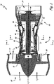
- FIG. 1 is a cross sectional view of gas turbine engine 10, in a turbofan embodiment.
- turbine engine 10 comprises fan 12 positioned in bypass duct 14, with bypass duct 14 oriented about a turbine core comprising compressor section 16, combustor or combustors 18, and turbine section 20, arranged in flow series with upstream inlet 22 and downstream exhaust 24.
- Compressor section 16 may comprise stages of compressor vanes 26 and blades 28 arranged in low pressure compressor section 30 and high pressure compressor section 32.
- Turbine section 20 may comprise stages of turbine vanes 34 and turbine blades 36 arranged in high pressure turbine section 38 and low pressure turbine section 40.
- the high pressure turbine section 38 may be coupled to the high pressure compressor section 32 via a first shaft 42, thereby forming a high pressure spool or high spool.
- the low pressure turbine section 40 may be coupled to the low pressure compressor section 30 and fan 12 via a second shaft 44, forming a low pressure spool or low spool.
- the shafts 42 and 44 may be coaxially mounted, with the high and low spools independently rotating about turbine axis (centerline) CL.
- Fan 12 comprises a number of fan airfoils circumferentially arranged around a fan disk or other rotating member, which is coupled directly or indirectly to the low pressure compressor section 30 and driven by shaft 44.
- the fan 12 may be coupled to the fan spool via a geared fan drive mechanism 46, providing independent fan speed control.
- fan 12 is forward-mounted and provides thrust by accelerating flow downstream through bypass duct 14.
- fan 12 may be an unducted fan or propeller assembly, in either a forward or aft-mounted configuration.
- turbine engine 10 may comprise any of a high-bypass turbofan, a low-bypass turbofan or a turboprop engine, and the number of spools and the shaft configurations may vary.
- marine and land based turbines that may or may not have a fan or propeller.
- incoming airflow F1 enters inlet 22 and divides into core flow FC and bypass flow FB, downstream of fan 12.
- Core flow FC propagates along the core flowpath through compressor section 16, combustor 18 and turbine section 2, and bypass flow FB propagates along the bypass flowpath through bypass duct 14.
- Low pressure compressor section 30 and high pressure compressor section 32 are utilized to compress incoming air for combustor 18, where fuel is introduced, mixed with air and ignited to produce hot combustion gas.
- fan 12 may also provide some degree of compression or pre-compression to core flow FC and low pressure compressor section 30 may be omitted.
- thermodynamic efficiency of turbine engine 10 is tied to the overall pressure ratio, as defined between the delivery pressure at inlet 22 and the compressed air pressure entering combustor 18 from compressor section 16.
- a higher pressure ratio offers increased efficiency and improved performance, including greater specific thrust.
- High pressure ratios also result in increased peak gas path temperatures, higher core pressure and greater flow rates, increasing thermal and mechanical stress on engine components.
- FIG. 2 is a cross section along line 22 of FIG. 1 of a casing 48 which has a rotor shaft 50 inside. Vanes 26 are attached to casing 48 and the gas path 52 is shown as the space between vanes 26.
- Abrasive coating 60 corresponding to the abrasive coating described hereinafter, is formed on rotor shaft 50 such that the clearance C between abrasive coating 60 and vane tips 26T has the proper tolerance for operation of the engine, e.g. to serve as a seal to prevent leakage of air (thus reducing efficiency), while not interfering with relative movement of the vanes and rotor shaft.
- clearance C is expanded for purposes of illustration.
- clearance C may be, for example, in a range of about 0.025 inches (0.635 mm) to 0.055 inches (1.397 mm) when the engine is cold and 0.000 to 0.03 inches (0.762 mm) during engine operation, depending on the specific operation conditions and previous rub events that may have occurred.
- FIG. 3 shows the cross section along line 3-3 of FIG. 2 , with casing 48 and vane 26.
- An abrasive coating 60 is attached to rotor shaft 50, with a clearance C between coating 60 and vane tip 26T of vane 26 that varies with operating conditions, as described herein.
- FIG. 3 shows an embodiment comprising a bi-layer coating 60 which includes a metallic bond coat 62 and an abrasive layer 66.
- Metallic bond coat 62 may be applied to the rotor shaft 50.
- Abrasive layer 66 may be deposited on top of bond coat 62 and may be the layer which first encounters vane tip 26T.
- Bond coat 62 is thin, up to about 254 microns (10 mils), more specifically ranging from about about 76 to about 178 microns (3 mils to about 7 mils).
- Abrasive coating layer 66 may be about the same thickness as bond coat 62, again ranging from about 76 to about 178 microns (about 3 mils to about 7 mils), while some applications that have larger variation in tip clearance may require a thicker abrasive layer 66.
- Abrasive layer 66 may be as thick as 7620 microns (300 mils) in some applications.
- the bond coat forming the layer 62 may be MCr, MCrAl, MCrAlY or a refractory modified MCrAlY, where M is nickel, cobalt, iron, or mixtures thereof.
- bond coat 62 may be 15 - 40 wt% Cr, 6 - 15 wt% Al, 0.61 to 1.0 wt% Y, and the balance is at least one of cobalt, nickel, and/or iron.
- the abrasive layer 66 has a composite matrix of a metal or metal alloy loaded with soft or weak filler into which flat or angular thermal ceramic particles or inclusions have been added.
- the metal used in the abrasive layer 66 may be at least one of Ni, Co, Cu, and Al.
- the metal alloys used in the abrasive layer 66 may be at least one of a nickel based alloy, a copper based alloy, a cobalt based alloy, an aluminum based alloy, and a MCrAlY where M is selected from the group consisting of nickel, cobalt, iron, and mixtures thereof.
- Suitable metal alloys which may be used include Ni20Cr, copper-nickel alloys, and copper-aluminum bronzes.
- the amount of a metal present in the abrasive layer 66, such as nickel or nickel alloy, to the soft or weak filler, such as hexagonal boron nitride, in the abradable matrix may range from about 30% to 60% by volume, and more specifically, in the case of nickel as the metal, from about 40% to about 50% nickel by volume, with the balance being hBN as the filler.
- the ceramic particles may be any ceramic that has a hardness of seven or more on the Mohs Scale for hardness, such as silica, cubic boron nitride, quartz, alumina, and zirconia, and that at least partially melts at the spray temperatures.
- the amount of ceramic in abrasive layer 66 ranges from about 1.0% to 10% by volume.
- the amount of metal alloy in the abrasive layer 66 may range from about 30% to 60% by volume and the balance, from about 30% to about 69% by volume, is the soft or weak filler selected from the group consisting of hexagonal boron nitride (hBN), bentonite clay, talc, graphite, glass or ceramic microspheres, and loosely bonded agglomerates of a ceramic, like alumina.
- the ceramic particles may be formed from any suitable grit media.
- the nickel alloy, the soft or weak filler, such as hBN, and a ceramic material may be deposited as a coating on the structure in proximity to the tips 26T of the airfoils, such as vanes 26, using an air plasma spray technique to deposit the material onto a turbine engine component such as the rotor shaft 50.
- an air plasma spray technique to deposit the material onto a turbine engine component such as the rotor shaft 50.
- one may individually feed the powders to one or more spray heads or may blend the powders and then feed them to one or more spray heads.
- Other spray processes would also be effective, such as combustion flame spray, HVOF, HVAF, LPPS, VPS, HVPS and the like.
- the abrasive layer 66 is a quantity of ceramic particles that may at least partially melt during the spray process to form disc like flat particles, or splat particles, when the droplets of molten particles contact the rotor shaft 50.
- the ceramic particles may be injected into a cooler, downstream area of the plasma plume so that the ceramic particles mechanically embed into the coating without melting. This alternative approach allows the ceramic particles to have a better cutting capability.
- the abrasive layer 66 may be engineered to have an interparticle strength, the strength between the particles of the abrasive layer, which in a first or normal mode of operation of the gas turbine engine allows the abrasive layer 66 to wear the metal tips 26T of the vane airfoils. By wear, it is meant that metal is removed from the tips 26T. During this mode of operation, the rub forces are at a low radial interaction rate and the bonding between the particles should be strong enough to withstand operational stresses such as those caused by centrifugal forces and thermal stresses.
- the interparticle strength of the layer 66 in a second mode of operation one characterized by hard rubs between the tips 26T and the abrasive layer 66, allows the material forming the abrasive layer 66 to fracture and liberate particles in the abrasive layer 66.
- Hard rubs are caused by high interaction rates associated with surge, bird strike, severe vibration, etc. In this way, the rub forces are limited.
- airfoils such as the vanes 26, may move radially.
- Normal operation, or the first mode of operation of the gas turbine engine is one in which the airfoils move at a rate of less than 1.27 mm (50 mils) per second, usually less than 0.254 mm (10 mils) per second.
- Hard rub situations occur when the airfoils move at a rate greater than 12.7 mm (0.5 inch) per second.
- the abrasive layer 66 is not a fully dense coating and may have a porosity less than about 15%.
- the porosity of the abrasive layer 66 creates a surface roughness which allows gas permeability to reduce the aerodynamic effect.
- the abrasive layer may be provided with a porosity in the range of from 3.0 to 8.0%.
- the porosity of the final abrasive layer 66 may be controlled during the spray application of the abrasive layer 66.
- the abrasive layer 66 may be deposited on a turbine engine component in close proximity to the tips of airfoils such as those in the compressor section and the turbine section of the gas turbine engine.
- the abrasive layer 66 may be deposited on the casing 48 and/or the rotor shaft 50 using a spray process such as an air plasma spray.
- a feedstock used during the air plasma spray process may comprise 15 vol% to 45 vol% of a metal or metal alloy, from 0.5 vol% to 15 vol% ceramic particles, and hexagonal boron nitride or another filler selected from the group consisting of bentonite clay, talc, graphite, glass or ceramic microspheres, and loosely bonded agglomerates of a ceramic such as alumina as a remainder.
- a feedstock used during the air plasma spray process may comprises composite particles of from 20 vol% to 30 vol% Ni20Cr and the remainder being hBN with constituent particles of 1.0 to 25 microns in diameter and agglomerate particles sized in the range of from 25 to 150 micron particle size diameter.
- the Ni20Cr and hBN particles may be co-sprayed with aluminum oxide based abrasive particles of from 50 - 150 microns in diameter so as to produce a coating with from 1.0 to 10 vol% of abrasive particles.
- a 3MB plasma spray torch with a #705 nozzle running on 100 scfh of argon and 10 scfh of hydrogen may be used to deposit the abrasive layer 66.
- the abrasive layer 66 may be deposited at a temperature which creates splats of the ceramic particles on the turbine engine component. During this process, the droplets of ceramic particles spread out to form the splat upon contact with the turbine engine component.
- the splats of ceramic particles may have a longitudinal dimension greater than 25 microns.
- the resultant abrasive layer 66 may have a cohesive strength of from 300 to 1200 psi (2.068 to 8.274 MPa).
- the abrasive layer 66 may be deposited on an intermediate thermally insulating layer to further protect the rotor shaft from burn through during excessive vane contact.
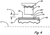
- FIG. 4 shows an embodiment comprising tri-layer coating 60, which includes intermediate insulating ceramic layer 64 between abrasive layer 66 and bottom bond coat layer 62.
- Optional ceramic layer 64 may be any of the zirconia based ceramics such as are described in U.S. Patent Nos. 4,861,618 , 5,879,573 , 6,102,656 and 6,358,002 .
- Zirconia stabilized with 6-8wt% yttrium is one example of such a ceramic layer 64.
- Other examples are zirconia stabilized with feria, magnesia, mullite, calcia, and mixtures thereof.
- Thermally insulating ceramic layer 64 thickness may range from about 178 to about 305 microns (about 7 mils to about 12 mils). In many instances, there is no need for optionally thermally insulating ceramic layer 64 because abrasive coating 66 functions to remove material by low temperature abrasion minimizing or eliminating thermal burn through of the rotor in high interaction rate events.
- Coating 70 is provided on the inner diameter surface of casing or shroud 48.
- Coating 70 includes a first metallic bond coat 72 that has been applied to the inner diameter (ID) of stator casing 48.
- stator casing 48 includes a shroud that forms a blade air seal.
- Abrasive layer 76 may be formed on metallic bond coating 72 and is the layer that first encounters rotor tip 28T.
- Coating 66 and 76 during fast and/or deep rubs, known as hard rubs, is engineered to have an interparticle strength which allows the coating 66 and 76 to fracture, and thus prevent catastrophic runaway events and damage to turbine components.
- Hard rubs result from events such as surge, bird strike, severe vibration, shaft deflections, vibrational modes, and hard landings.
- a hard rub would be characterized by the airfoil moving radially at a rate of 0.5 inch (12.7 mm) per second.
- a 1,000 psi (6.895 MPa) coating strength relates to about 20 pounds (89 N) per vane loading of compressor stators. Because the bulk coating of the abrasive layer 66 and 76 must meet the durability requirements of the environment, such as the high G environment of the shaft outside diameter in a cantilevered vane sealing application, the abrasive coating 66 and 76 has a strength of greater than about 300 psi (2.068 MPa).
Landscapes
- Engineering & Computer Science (AREA)
- Chemical & Material Sciences (AREA)
- Organic Chemistry (AREA)
- Mechanical Engineering (AREA)
- Materials Engineering (AREA)
- General Engineering & Computer Science (AREA)
- Wood Science & Technology (AREA)
- Life Sciences & Earth Sciences (AREA)
- Physics & Mathematics (AREA)
- Plasma & Fusion (AREA)
- Metallurgy (AREA)
- Chemical Kinetics & Catalysis (AREA)
- Nanotechnology (AREA)
- Inorganic Chemistry (AREA)
- Turbine Rotor Nozzle Sealing (AREA)
Claims (11)
- Revêtement abrasif (60 ; 70) destiné à être utilisé dans un moteur à turbine à gaz, ledit revêtement abrasif comprenant :ledit revêtement abrasif (60 ; 70) étant appliqué sur une structure de moteur à turbine à gaz à proximité immédiate d'au moins une section dudit moteur à turbine à gaz ayant une pluralité de profils aérodynamiques (26 ; 28) ;ledit revêtement abrasif (60 ; 70) dans un premier mode de fonctionnement dudit moteur à turbine à gaz étant capable de provoquer l'usure des pointes (26T ; 28T) desdits profils aérodynamiques (26 ; 28) qui entrent en contact avec le revêtement abrasif (60 ; 70) ; caractérisé en ce que :ledit revêtement abrasif (60; 70) est constitué de particules de céramique angulaires ayant une dimension longitudinale comprise entre 50 et 150 microns intégrées dans une matrice d'un matériau de remplissage souple ou fragile et au moins un métal ou un alliage métallique choisi parmi le groupe constitué du nickel, des alliages à base de nickel, du cuivre, des alliages à base de cuivre, du cobalt, des alliages à base de cobalt, de l'aluminium, des alliages d'aluminium, du MCrAlY où M comprend au moins l'un parmi le nickel, le cobalt et le fer, et des mélanges de ceux-ci ; etledit revêtement abrasif (60 ; 70) dans un second mode de fonctionnement de dudit moteur à turbine à gaz ayant une force interparticulaire suffisante pour permettre la fracture dudit revêtement (60 ; 70) pour limiter les forces de frottement sur les profils aérodynamiques (26 ; 28).
- Revêtement abrasif selon la revendication 1, dans lequel ledit revêtement abrasif (60 ; 70) porte lesdites pointes (26T ; 28T) desdits profils aérodynamiques (26 ; 28) pendant de faibles taux d'interaction radiale entre ledit revêtement abrasif (60 ; 70) et lesdits profils aérodynamiques (26 ; 28) et dans lequel ledit revêtement abrasif (60 ; 70) se fracture au cours de taux d'interaction élevés entre ledit revêtement abrasif (60 ; 70) et lesdits profils aérodynamiques (26 ; 28) pour limiter lesdites forces de frottement.
- Revêtement abrasif selon la revendication 1 ou la revendication 2, dans lequel ledit matériau de remplissage souple ou fragile est choisi dans le groupe constitué du nitrure de bore hexagonal, de l'argile bentonite, des microsphères de talc, de graphite, de verre ou de céramique et des agglomérats de céramique faiblement liés.
- Revêtement abrasif selon une quelconque revendication précédente, dans lequel lesdites particules de céramique ont une force suffisante pour couper les pointes (26T ; 28T) desdits profils aérodynamiques (26 ; 28).
- Revêtement abrasif selon une quelconque revendication précédente, dans lequel lesdites particules de céramique sont choisies dans le groupe constitué des particules d'oxyde d'aluminium, de la zircone, du nitrure de bore cubique, du carbure de silicium, des alliages et des mélanges de ceux-ci.
- Procédé de formation d'un joint dans un moteur à turbine à gaz (10), le procédé comprenant :la fourniture dudit moteur à turbine à gaz (10) avec au moins une section ayant au moins un profil aérodynamique (26 ; 28) avec une pointe en métal nu (26T ; 28T) ;la fourniture d'au moins une structure à proximité dudit au moins un profil aérodynamique (26 ; 28) avec ladite pointe en métal nu (26T ; 28T) ; etl'application d'un revêtement abrasif (60 ; 70) ayant un premier mode dans lequel ledit revêtement (60 ; 70) retire le métal de ladite pointe de profil aérodynamique (26T ; 28T) ; caractérisé en ce que :ledit revêtement abrasif (60 ; 70) est constitué de particules de céramique angulaires ayant une dimension longitudinale comprise entre 50 et 150 microns intégrées dans une matrice d'un matériau de remplissage souple ou fragile et au moins un métal ou un alliage métallique choisi parmi le groupe constitué du nickel, des alliages à base de nickel, du cuivre, des alliages à base de cuivre, du cobalt, des alliages à base de cobalt, de l'aluminium, des alliages d'aluminium, du MCrAlY où M comprend au moins l'un parmi le nickel, le cobalt et le fer, et des mélanges de ceux-ci ; etledit revêtement abrasif a un second mode dans lequel ledit revêtement abrasif (60 ; 70) se fracture sur ladite au moins une structure pour limiter les forces de frottement sur ledit au moins un profil aérodynamique (26 ; 28).
- Procédé selon la revendication 6, dans lequel ledit au moins un profil aérodynamique (26 ; 28) se déplace radialement pendant le fonctionnement dudit moteur à turbine à gaz (10) et ledit revêtement abrasif (60 ; 70) est dans ledit premier mode lorsque ledit au moins un profil aérodynamique (26 ; 28) se déplace de moins de 10 mils par seconde, et/ou dans lequel ledit revêtement abrasif (60 ; 70) est dans ledit second mode lorsque ledit au moins un profil aérodynamique (26 ; 28) se déplace de plus de 1,27 cm (0,5 pouce) par seconde.
- Procédé selon la revendication 6 ou la revendication 7,
dans
lequel ladite étape d'application de revêtement abrasif comprend la fourniture d'une charge d'alimentation contenant un métal ou un alliage métallique, du nitrure de bore hexagonal, et des particules de céramique, l'introduction de ladite charge d'alimentation au niveau d'une buse, et la projection de plasma d'air dudit métal ou alliage métallique, dudit nitrure de bore hexagonal, et desdites particules de céramique sur ladite au moins une structure, dans lequel, éventuellement, ladite étape de projection de plasma d'air est réalisée à une température qui entraîne des gouttelettes de particules de céramique pour former et être déposées sur ladite au moins une structure sous forme d'éclaboussure. - Procédé selon la revendication 8, dans lequel ladite étape de fourniture de charge d'alimentation comprend la fourniture dudit métal ou alliage métallique présent en une quantité de 15 % en volume à 45 % en volume, la fourniture desdites particules de céramique en une quantité de 0,5 % en volume à 15 % en volume et la fourniture du nitrure de bore hexagonal en tant que reste.
- Procédé selon la revendication 9, dans lequel ladite étape de fourniture de charge d'alimentation comprend la fourniture d'un premier composant constitué de 20 % en volume à 30 % en volume de Ni20Cr et le reste du nitrure de bore hexagonal ayant des particules constitutives de 1,0 micron à 25 microns en taille et une taille de particules agglomérées comprise entre 25 microns et 150 microns, et la fourniture d'un second composant constitué de particules abrasives à base d'oxyde d'aluminium ayant une taille comprise entre 50 et 150 microns.
- Procédé selon la revendication 10, dans lequel ladite étape d'application de revêtement comprend l'application d'un revêtement ayant de 1,0 à 10 % en volume de particules abrasives d'oxyde d'aluminium.
Applications Claiming Priority (1)
| Application Number | Priority Date | Filing Date | Title |
|---|---|---|---|
| US201462073099P | 2014-10-31 | 2014-10-31 |
Publications (2)
| Publication Number | Publication Date |
|---|---|
| EP3020931A1 EP3020931A1 (fr) | 2016-05-18 |
| EP3020931B1 true EP3020931B1 (fr) | 2018-02-28 |
Family
ID=54364189
Family Applications (1)
| Application Number | Title | Priority Date | Filing Date |
|---|---|---|---|
| EP15192369.5A Active EP3020931B1 (fr) | 2014-10-31 | 2015-10-30 | Revêtement de rotor abrasif présentant des caractéristiques de limitation de force de frottement |
Country Status (2)
| Country | Link |
|---|---|
| US (1) | US20160122552A1 (fr) |
| EP (1) | EP3020931B1 (fr) |
Families Citing this family (7)
| Publication number | Priority date | Publication date | Assignee | Title |
|---|---|---|---|---|
| EP3052787B1 (fr) | 2013-10-02 | 2021-12-15 | Raytheon Technologies Corporation | Système de joint à air et procédé pour former un système de joint à air |
| US10786875B2 (en) | 2014-07-02 | 2020-09-29 | Raytheon Technologies Corporation | Abrasive preforms and manufacture and use methods |
| WO2017177229A1 (fr) * | 2016-04-08 | 2017-10-12 | United Technologies Corporation | Géométries de joint pour limiter les fuites dans des turbines à gaz et procédés de formation |
| US10697464B2 (en) | 2016-07-29 | 2020-06-30 | Raytheon Technologies Corporation | Abradable material |
| US20180372111A1 (en) * | 2017-06-26 | 2018-12-27 | United Technologies Corporation | Compressor inner air seal and method of making |
| US10947901B2 (en) * | 2018-11-27 | 2021-03-16 | Honeywell International Inc. | Gas turbine engine compressor sections and intake ducts including soft foreign object debris endwall treatments |
| US11555452B1 (en) * | 2021-07-16 | 2023-01-17 | Raytheon Technologies Corporation | Ceramic component having silicon layer and barrier layer |
Family Cites Families (10)
| Publication number | Priority date | Publication date | Assignee | Title |
|---|---|---|---|---|
| US4861618A (en) | 1986-10-30 | 1989-08-29 | United Technologies Corporation | Thermal barrier coating system |
| CA2048804A1 (fr) * | 1990-11-01 | 1992-05-02 | Roger J. Perkins | Bouts d'aube mobile abrasifs longue duree |
| US6102656A (en) | 1995-09-26 | 2000-08-15 | United Technologies Corporation | Segmented abradable ceramic coating |
| US5932356A (en) * | 1996-03-21 | 1999-08-03 | United Technologies Corporation | Abrasive/abradable gas path seal system |
| US5879573A (en) | 1997-08-12 | 1999-03-09 | Vlsi Technology, Inc. | Method for optimizing a gap for plasma processing |
| SG72959A1 (en) * | 1998-06-18 | 2000-05-23 | United Technologies Corp | Article having durable ceramic coating with localized abradable portion |
| GB2399777A (en) * | 2002-11-01 | 2004-09-29 | Rolls Royce Plc | Abradable seals for gas turbine engines |
| US8038388B2 (en) * | 2007-03-05 | 2011-10-18 | United Technologies Corporation | Abradable component for a gas turbine engine |
| US9169740B2 (en) * | 2010-10-25 | 2015-10-27 | United Technologies Corporation | Friable ceramic rotor shaft abrasive coating |
| US20120189434A1 (en) * | 2011-01-26 | 2012-07-26 | United Technologies Corporation | Coating with abradability proportional to interaction rate |
-
2015
- 2015-10-27 US US14/923,538 patent/US20160122552A1/en not_active Abandoned
- 2015-10-30 EP EP15192369.5A patent/EP3020931B1/fr active Active
Non-Patent Citations (1)
| Title |
|---|
| None * |
Also Published As
| Publication number | Publication date |
|---|---|
| US20160122552A1 (en) | 2016-05-05 |
| EP3020931A1 (fr) | 2016-05-18 |
Similar Documents
| Publication | Publication Date | Title |
|---|---|---|
| EP3020931B1 (fr) | Revêtement de rotor abrasif présentant des caractéristiques de limitation de force de frottement | |
| EP2481890A2 (fr) | Joint d'étanchéité dans un composant de moteur de turbine à gaz ayant un revêtement avec capacité abrasive proportionnelle au taux d'interaction | |
| US9169740B2 (en) | Friable ceramic rotor shaft abrasive coating | |
| EP2444515B1 (fr) | Surface d'étanchéité en céramique dense et rugueuse dans les turbomachines | |
| EP2444513B1 (fr) | Revêtement céramique d'arbre de rotor abrasif | |
| EP2444514B1 (fr) | Procédé de production d'un revêtement abradable | |
| EP3440318B1 (fr) | Géométries de joint pour limiter les fuites dans des turbines à gaz et procédés de formation | |
| EP3276038B1 (fr) | Matériau abradable | |
| EP2428593B1 (fr) | Revêtement abradable doté d'un fusible de sécurité | |
| EP3239475B1 (fr) | Bande de frottement abradable de joint externe | |
| US20120099971A1 (en) | Self dressing, mildly abrasive coating for clearance control | |
| EP2540868B1 (fr) | Joint de turbine abradable résistant aux éclats | |
| EP3263843B1 (fr) | Bande de frottement isolé de joint externe | |
| EP2455589B1 (fr) | Découpage abrasif formé d'une pulvérisation thermique et post-traitement | |
| EP3626850B1 (fr) | Couche de collage pour revêtement céramique résistant aux spallations |
Legal Events
| Date | Code | Title | Description |
|---|---|---|---|
| PUAI | Public reference made under article 153(3) epc to a published international application that has entered the european phase |
Free format text: ORIGINAL CODE: 0009012 |
|
| AK | Designated contracting states |
Kind code of ref document: A1 Designated state(s): AL AT BE BG CH CY CZ DE DK EE ES FI FR GB GR HR HU IE IS IT LI LT LU LV MC MK MT NL NO PL PT RO RS SE SI SK SM TR |
|
| AX | Request for extension of the european patent |
Extension state: BA ME |
|
| RAP1 | Party data changed (applicant data changed or rights of an application transferred) |
Owner name: UNITED TECHNOLOGIES CORPORATION |
|
| STAA | Information on the status of an ep patent application or granted ep patent |
Free format text: STATUS: REQUEST FOR EXAMINATION WAS MADE |
|
| 17P | Request for examination filed |
Effective date: 20161118 |
|
| RBV | Designated contracting states (corrected) |
Designated state(s): AL AT BE BG CH CY CZ DE DK EE ES FI FR GB GR HR HU IE IS IT LI LT LU LV MC MK MT NL NO PL PT RO RS SE SI SK SM TR |
|
| RIC1 | Information provided on ipc code assigned before grant |
Ipc: F01D 11/00 20060101ALI20170731BHEP Ipc: C23C 4/134 20160101ALI20170731BHEP Ipc: C09D 5/00 20060101ALI20170731BHEP Ipc: F01D 11/12 20060101AFI20170731BHEP Ipc: C23C 4/11 20160101ALI20170731BHEP Ipc: C09D 7/12 20060101ALI20170731BHEP |
|
| GRAP | Despatch of communication of intention to grant a patent |
Free format text: ORIGINAL CODE: EPIDOSNIGR1 |
|
| STAA | Information on the status of an ep patent application or granted ep patent |
Free format text: STATUS: GRANT OF PATENT IS INTENDED |
|
| INTG | Intention to grant announced |
Effective date: 20170913 |
|
| GRAS | Grant fee paid |
Free format text: ORIGINAL CODE: EPIDOSNIGR3 |
|
| GRAA | (expected) grant |
Free format text: ORIGINAL CODE: 0009210 |
|
| STAA | Information on the status of an ep patent application or granted ep patent |
Free format text: STATUS: THE PATENT HAS BEEN GRANTED |
|
| AK | Designated contracting states |
Kind code of ref document: B1 Designated state(s): AL AT BE BG CH CY CZ DE DK EE ES FI FR GB GR HR HU IE IS IT LI LT LU LV MC MK MT NL NO PL PT RO RS SE SI SK SM TR |
|
| REG | Reference to a national code |
Ref country code: GB Ref legal event code: FG4D Ref country code: CH Ref legal event code: EP |
|
| REG | Reference to a national code |
Ref country code: AT Ref legal event code: REF Ref document number: 974374 Country of ref document: AT Kind code of ref document: T Effective date: 20180315 |
|
| REG | Reference to a national code |
Ref country code: IE Ref legal event code: FG4D |
|
| REG | Reference to a national code |
Ref country code: DE Ref legal event code: R096 Ref document number: 602015008296 Country of ref document: DE |
|
| REG | Reference to a national code |
Ref country code: NL Ref legal event code: MP Effective date: 20180228 |
|
| REG | Reference to a national code |
Ref country code: LT Ref legal event code: MG4D |
|
| REG | Reference to a national code |
Ref country code: AT Ref legal event code: MK05 Ref document number: 974374 Country of ref document: AT Kind code of ref document: T Effective date: 20180228 |
|
| PG25 | Lapsed in a contracting state [announced via postgrant information from national office to epo] |
Ref country code: ES Free format text: LAPSE BECAUSE OF FAILURE TO SUBMIT A TRANSLATION OF THE DESCRIPTION OR TO PAY THE FEE WITHIN THE PRESCRIBED TIME-LIMIT Effective date: 20180228 Ref country code: NL Free format text: LAPSE BECAUSE OF FAILURE TO SUBMIT A TRANSLATION OF THE DESCRIPTION OR TO PAY THE FEE WITHIN THE PRESCRIBED TIME-LIMIT Effective date: 20180228 Ref country code: CY Free format text: LAPSE BECAUSE OF FAILURE TO SUBMIT A TRANSLATION OF THE DESCRIPTION OR TO PAY THE FEE WITHIN THE PRESCRIBED TIME-LIMIT Effective date: 20180228 Ref country code: NO Free format text: LAPSE BECAUSE OF FAILURE TO SUBMIT A TRANSLATION OF THE DESCRIPTION OR TO PAY THE FEE WITHIN THE PRESCRIBED TIME-LIMIT Effective date: 20180528 Ref country code: LT Free format text: LAPSE BECAUSE OF FAILURE TO SUBMIT A TRANSLATION OF THE DESCRIPTION OR TO PAY THE FEE WITHIN THE PRESCRIBED TIME-LIMIT Effective date: 20180228 Ref country code: FI Free format text: LAPSE BECAUSE OF FAILURE TO SUBMIT A TRANSLATION OF THE DESCRIPTION OR TO PAY THE FEE WITHIN THE PRESCRIBED TIME-LIMIT Effective date: 20180228 Ref country code: HR Free format text: LAPSE BECAUSE OF FAILURE TO SUBMIT A TRANSLATION OF THE DESCRIPTION OR TO PAY THE FEE WITHIN THE PRESCRIBED TIME-LIMIT Effective date: 20180228 |
|
| PG25 | Lapsed in a contracting state [announced via postgrant information from national office to epo] |
Ref country code: BG Free format text: LAPSE BECAUSE OF FAILURE TO SUBMIT A TRANSLATION OF THE DESCRIPTION OR TO PAY THE FEE WITHIN THE PRESCRIBED TIME-LIMIT Effective date: 20180528 Ref country code: AT Free format text: LAPSE BECAUSE OF FAILURE TO SUBMIT A TRANSLATION OF THE DESCRIPTION OR TO PAY THE FEE WITHIN THE PRESCRIBED TIME-LIMIT Effective date: 20180228 Ref country code: RS Free format text: LAPSE BECAUSE OF FAILURE TO SUBMIT A TRANSLATION OF THE DESCRIPTION OR TO PAY THE FEE WITHIN THE PRESCRIBED TIME-LIMIT Effective date: 20180228 Ref country code: LV Free format text: LAPSE BECAUSE OF FAILURE TO SUBMIT A TRANSLATION OF THE DESCRIPTION OR TO PAY THE FEE WITHIN THE PRESCRIBED TIME-LIMIT Effective date: 20180228 Ref country code: SE Free format text: LAPSE BECAUSE OF FAILURE TO SUBMIT A TRANSLATION OF THE DESCRIPTION OR TO PAY THE FEE WITHIN THE PRESCRIBED TIME-LIMIT Effective date: 20180228 Ref country code: GR Free format text: LAPSE BECAUSE OF FAILURE TO SUBMIT A TRANSLATION OF THE DESCRIPTION OR TO PAY THE FEE WITHIN THE PRESCRIBED TIME-LIMIT Effective date: 20180529 |
|
| REG | Reference to a national code |
Ref country code: FR Ref legal event code: PLFP Year of fee payment: 4 |
|
| PG25 | Lapsed in a contracting state [announced via postgrant information from national office to epo] |
Ref country code: IT Free format text: LAPSE BECAUSE OF FAILURE TO SUBMIT A TRANSLATION OF THE DESCRIPTION OR TO PAY THE FEE WITHIN THE PRESCRIBED TIME-LIMIT Effective date: 20180228 Ref country code: RO Free format text: LAPSE BECAUSE OF FAILURE TO SUBMIT A TRANSLATION OF THE DESCRIPTION OR TO PAY THE FEE WITHIN THE PRESCRIBED TIME-LIMIT Effective date: 20180228 Ref country code: PL Free format text: LAPSE BECAUSE OF FAILURE TO SUBMIT A TRANSLATION OF THE DESCRIPTION OR TO PAY THE FEE WITHIN THE PRESCRIBED TIME-LIMIT Effective date: 20180228 Ref country code: EE Free format text: LAPSE BECAUSE OF FAILURE TO SUBMIT A TRANSLATION OF THE DESCRIPTION OR TO PAY THE FEE WITHIN THE PRESCRIBED TIME-LIMIT Effective date: 20180228 Ref country code: AL Free format text: LAPSE BECAUSE OF FAILURE TO SUBMIT A TRANSLATION OF THE DESCRIPTION OR TO PAY THE FEE WITHIN THE PRESCRIBED TIME-LIMIT Effective date: 20180228 |
|
| REG | Reference to a national code |
Ref country code: DE Ref legal event code: R097 Ref document number: 602015008296 Country of ref document: DE |
|
| PG25 | Lapsed in a contracting state [announced via postgrant information from national office to epo] |
Ref country code: DK Free format text: LAPSE BECAUSE OF FAILURE TO SUBMIT A TRANSLATION OF THE DESCRIPTION OR TO PAY THE FEE WITHIN THE PRESCRIBED TIME-LIMIT Effective date: 20180228 Ref country code: SM Free format text: LAPSE BECAUSE OF FAILURE TO SUBMIT A TRANSLATION OF THE DESCRIPTION OR TO PAY THE FEE WITHIN THE PRESCRIBED TIME-LIMIT Effective date: 20180228 Ref country code: CZ Free format text: LAPSE BECAUSE OF FAILURE TO SUBMIT A TRANSLATION OF THE DESCRIPTION OR TO PAY THE FEE WITHIN THE PRESCRIBED TIME-LIMIT Effective date: 20180228 Ref country code: SK Free format text: LAPSE BECAUSE OF FAILURE TO SUBMIT A TRANSLATION OF THE DESCRIPTION OR TO PAY THE FEE WITHIN THE PRESCRIBED TIME-LIMIT Effective date: 20180228 |
|
| RIC2 | Information provided on ipc code assigned after grant |
Ipc: C09D 5/00 20060101ALI20170731BHEP Ipc: F01D 11/00 20060101ALI20170731BHEP Ipc: C09D 7/12 20181130ALI20170731BHEP Ipc: C23C 4/134 20160101ALI20170731BHEP Ipc: F01D 11/12 20060101AFI20170731BHEP Ipc: C23C 4/11 20160101ALI20170731BHEP |
|
| PLBE | No opposition filed within time limit |
Free format text: ORIGINAL CODE: 0009261 |
|
| STAA | Information on the status of an ep patent application or granted ep patent |
Free format text: STATUS: NO OPPOSITION FILED WITHIN TIME LIMIT |
|
| REG | Reference to a national code |
Ref country code: CH Ref legal event code: PK Free format text: BERICHTIGUNGEN |
|
| REG | Reference to a national code |
Ref country code: CH Ref legal event code: PK Free format text: BERICHTIGUNGEN |
|
| 26N | No opposition filed |
Effective date: 20181129 |
|
| RIC2 | Information provided on ipc code assigned after grant |
Ipc: F01D 11/12 20060101AFI20170731BHEP Ipc: F01D 11/00 20060101ALI20170731BHEP Ipc: C09D 7/12 20060101ALI20170731BHEP Ipc: C09D 5/00 20060101ALI20170731BHEP Ipc: C23C 4/11 20160101ALI20170731BHEP Ipc: C23C 4/134 20160101ALI20170731BHEP |
|
| PG25 | Lapsed in a contracting state [announced via postgrant information from national office to epo] |
Ref country code: SI Free format text: LAPSE BECAUSE OF FAILURE TO SUBMIT A TRANSLATION OF THE DESCRIPTION OR TO PAY THE FEE WITHIN THE PRESCRIBED TIME-LIMIT Effective date: 20180228 |
|
| REG | Reference to a national code |
Ref country code: CH Ref legal event code: PL |
|
| REG | Reference to a national code |
Ref country code: BE Ref legal event code: MM Effective date: 20181031 |
|
| PG25 | Lapsed in a contracting state [announced via postgrant information from national office to epo] |
Ref country code: MC Free format text: LAPSE BECAUSE OF FAILURE TO SUBMIT A TRANSLATION OF THE DESCRIPTION OR TO PAY THE FEE WITHIN THE PRESCRIBED TIME-LIMIT Effective date: 20180228 Ref country code: LU Free format text: LAPSE BECAUSE OF NON-PAYMENT OF DUE FEES Effective date: 20181030 |
|
| REG | Reference to a national code |
Ref country code: IE Ref legal event code: MM4A |
|
| PG25 | Lapsed in a contracting state [announced via postgrant information from national office to epo] |
Ref country code: BE Free format text: LAPSE BECAUSE OF NON-PAYMENT OF DUE FEES Effective date: 20181031 Ref country code: LI Free format text: LAPSE BECAUSE OF NON-PAYMENT OF DUE FEES Effective date: 20181031 Ref country code: CH Free format text: LAPSE BECAUSE OF NON-PAYMENT OF DUE FEES Effective date: 20181031 |
|
| PG25 | Lapsed in a contracting state [announced via postgrant information from national office to epo] |
Ref country code: IE Free format text: LAPSE BECAUSE OF NON-PAYMENT OF DUE FEES Effective date: 20181030 |
|
| PG25 | Lapsed in a contracting state [announced via postgrant information from national office to epo] |
Ref country code: MT Free format text: LAPSE BECAUSE OF NON-PAYMENT OF DUE FEES Effective date: 20181030 |
|
| PG25 | Lapsed in a contracting state [announced via postgrant information from national office to epo] |
Ref country code: TR Free format text: LAPSE BECAUSE OF FAILURE TO SUBMIT A TRANSLATION OF THE DESCRIPTION OR TO PAY THE FEE WITHIN THE PRESCRIBED TIME-LIMIT Effective date: 20180228 |
|
| PG25 | Lapsed in a contracting state [announced via postgrant information from national office to epo] |
Ref country code: PT Free format text: LAPSE BECAUSE OF FAILURE TO SUBMIT A TRANSLATION OF THE DESCRIPTION OR TO PAY THE FEE WITHIN THE PRESCRIBED TIME-LIMIT Effective date: 20180228 |
|
| PG25 | Lapsed in a contracting state [announced via postgrant information from national office to epo] |
Ref country code: HU Free format text: LAPSE BECAUSE OF FAILURE TO SUBMIT A TRANSLATION OF THE DESCRIPTION OR TO PAY THE FEE WITHIN THE PRESCRIBED TIME-LIMIT; INVALID AB INITIO Effective date: 20151030 Ref country code: MK Free format text: LAPSE BECAUSE OF NON-PAYMENT OF DUE FEES Effective date: 20180228 |
|
| PG25 | Lapsed in a contracting state [announced via postgrant information from national office to epo] |
Ref country code: IS Free format text: LAPSE BECAUSE OF FAILURE TO SUBMIT A TRANSLATION OF THE DESCRIPTION OR TO PAY THE FEE WITHIN THE PRESCRIBED TIME-LIMIT Effective date: 20180628 |
|
| REG | Reference to a national code |
Ref country code: DE Ref legal event code: R081 Ref document number: 602015008296 Country of ref document: DE Owner name: RAYTHEON TECHNOLOGIES CORPORATION (N.D.GES.D.S, US Free format text: FORMER OWNER: UNITED TECHNOLOGIES CORPORATION, FARMINGTON, CONN., US |
|
| P01 | Opt-out of the competence of the unified patent court (upc) registered |
Effective date: 20230520 |
|
| PGFP | Annual fee paid to national office [announced via postgrant information from national office to epo] |
Ref country code: DE Payment date: 20230920 Year of fee payment: 9 |
|
| PGFP | Annual fee paid to national office [announced via postgrant information from national office to epo] |
Ref country code: GB Payment date: 20240919 Year of fee payment: 10 |
|
| PGFP | Annual fee paid to national office [announced via postgrant information from national office to epo] |
Ref country code: FR Payment date: 20240919 Year of fee payment: 10 |