EP3020925A1 - Rotor blade with edge protection - Google Patents
Rotor blade with edge protection Download PDFInfo
- Publication number
- EP3020925A1 EP3020925A1 EP15187411.2A EP15187411A EP3020925A1 EP 3020925 A1 EP3020925 A1 EP 3020925A1 EP 15187411 A EP15187411 A EP 15187411A EP 3020925 A1 EP3020925 A1 EP 3020925A1
- Authority
- EP
- European Patent Office
- Prior art keywords
- blade
- sheath
- rotating blade
- radial
- core
- Prior art date
- Legal status (The legal status is an assumption and is not a legal conclusion. Google has not performed a legal analysis and makes no representation as to the accuracy of the status listed.)
- Withdrawn
Links
Images


Classifications
-
- F—MECHANICAL ENGINEERING; LIGHTING; HEATING; WEAPONS; BLASTING
- F01—MACHINES OR ENGINES IN GENERAL; ENGINE PLANTS IN GENERAL; STEAM ENGINES
- F01D—NON-POSITIVE DISPLACEMENT MACHINES OR ENGINES, e.g. STEAM TURBINES
- F01D5/00—Blades; Blade-carrying members; Heating, heat-insulating, cooling or antivibration means on the blades or the members
- F01D5/12—Blades
- F01D5/28—Selecting particular materials; Particular measures relating thereto; Measures against erosion or corrosion
-
- F—MECHANICAL ENGINEERING; LIGHTING; HEATING; WEAPONS; BLASTING
- F01—MACHINES OR ENGINES IN GENERAL; ENGINE PLANTS IN GENERAL; STEAM ENGINES
- F01D—NON-POSITIVE DISPLACEMENT MACHINES OR ENGINES, e.g. STEAM TURBINES
- F01D5/00—Blades; Blade-carrying members; Heating, heat-insulating, cooling or antivibration means on the blades or the members
- F01D5/12—Blades
- F01D5/14—Form or construction
- F01D5/147—Construction, i.e. structural features, e.g. of weight-saving hollow blades
-
- F—MECHANICAL ENGINEERING; LIGHTING; HEATING; WEAPONS; BLASTING
- F01—MACHINES OR ENGINES IN GENERAL; ENGINE PLANTS IN GENERAL; STEAM ENGINES
- F01D—NON-POSITIVE DISPLACEMENT MACHINES OR ENGINES, e.g. STEAM TURBINES
- F01D5/00—Blades; Blade-carrying members; Heating, heat-insulating, cooling or antivibration means on the blades or the members
- F01D5/12—Blades
- F01D5/28—Selecting particular materials; Particular measures relating thereto; Measures against erosion or corrosion
- F01D5/282—Selecting composite materials, e.g. blades with reinforcing filaments
-
- F—MECHANICAL ENGINEERING; LIGHTING; HEATING; WEAPONS; BLASTING
- F01—MACHINES OR ENGINES IN GENERAL; ENGINE PLANTS IN GENERAL; STEAM ENGINES
- F01D—NON-POSITIVE DISPLACEMENT MACHINES OR ENGINES, e.g. STEAM TURBINES
- F01D5/00—Blades; Blade-carrying members; Heating, heat-insulating, cooling or antivibration means on the blades or the members
- F01D5/12—Blades
- F01D5/28—Selecting particular materials; Particular measures relating thereto; Measures against erosion or corrosion
- F01D5/286—Particular treatment of blades, e.g. to increase durability or resistance against corrosion or erosion
-
- F—MECHANICAL ENGINEERING; LIGHTING; HEATING; WEAPONS; BLASTING
- F05—INDEXING SCHEMES RELATING TO ENGINES OR PUMPS IN VARIOUS SUBCLASSES OF CLASSES F01-F04
- F05D—INDEXING SCHEME FOR ASPECTS RELATING TO NON-POSITIVE-DISPLACEMENT MACHINES OR ENGINES, GAS-TURBINES OR JET-PROPULSION PLANTS
- F05D2250/00—Geometry
- F05D2250/30—Arrangement of components
- F05D2250/38—Arrangement of components angled, e.g. sweep angle
Definitions
- the present disclosure relates in general to the configuration of rotor blade edge protection, including such edge protection applied to composite material blades and more specifically to protection for three dimensionally formed leading and trailing blade edges.
- U.S. Patent no. 7,896,221 B2 discusses a manufacturing method that provides a portion of a blade aerofoil with increased erosion resistance. This is achieved by the use of titanium elements and a beta-stabilizing material. The titanium elements and the beta-stabilizing material are assembled such that the beta-stabilizing material is adjacent to the titanium elements. When heated the beta-stabilizing material diffuses into an adjacent portion of the titanium elements causing the adjacent portion of the one or more elements to have a beta microstructure which provides an increased erosion resistance. This solution requires the assembly of multiple elements in order to from an erosion resistance blade edge.
- U.S patent No 5,782,607 discusses a further method that involves using replaceable ceramic insert that forms part of a protective sheath of a leading edge of a propeller blade providing a protective sheath.
- a securing means such as adhesive, a screw or a pin.
- edge sheaths In particularly for turbines blades that have edges curved in the circumferential direction, these solutions require the edge sheaths to be made of numerous smaller pieces bonded together.
- a blade a sheath fitted to a curved edge wherein the sheath is configured to overcome the problem of how to fit an inflexible sheath as a single piece to a curved edge of the blade.
- the disclosure is based on the general idea of providing a solid leading edge or trailing edge to a blade having a core body that may be made of carbon fiber reinforced polymer or other material susceptible to erosion.
- a feature of the leading/training edge mount is its geometry with respect to the inner shape of the interface between the leading/trailing edge and the core body. The geometry is such that the sheath has a uniform assembly direction over the radial height of the sheath, which can be a straight or curved trajectory. This is achieved by the sheath covering a part of the core to form either a leading or trailing edge being configured such that despite the curvature of the covering edge, the sheath has a fixed assembly angle on the core.
- One general aspect includes a rotating blade having a rotational axis around which the blade rotates and first and second surfaces.
- the blade also includes an edge, defined by a junction, in a radial direction, of the first surface and the second surface, wherein the edge is curved in a circumferential direction.
- a sheath formed around the edge has a radial height between radial distal ends of the sheath and further has a head section that covers the edge of the blade.
- the radial height of the sheath may extend either over a fully radial height of the edge of the blade or a partial radial height of the edge of the blade.
- a first portion that projects from the head section along the first surface of the rotating blade has a first inner surface that, as viewed from a circumferential section defined as a section taken at a fixed distance from the rotational axis, is essentially straight at any point of the radial height, and a first tangential vector projected tangentially to the first inner surface in a direction away from the head section in a longitudinal plain so as to form a first angle with the rotational axis that does not vary over the radial height.
- a second portion, projecting from the head section along the second surface of the rotating blade, comprises a second inner surface, wherein a second tangential vector projected tangentially from any point of the second inner diverges from the first tangential vector in the direction of extension of the second portion from the head portion.
- the first inner surface as viewed in a circumferential section, is essential straight at any point of the radial height.
- the rotating blade edge is a leading edge.
- the first surface is a pressure surface of the blade and the second surface is a suction surface of the blade.
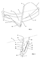
- FIG. 1 An exemplary embodiment shown in Fig. 1 is a rotating blade that is configured and arranged to rotate around a rotational axis 2, which in the radial direction forms a longitudinal plain.
- the blade comprises a leading edge 7, trailing edge 8 a pressure surface 5 and a suction surface 6.
- the leading edge 7 is curved along a radial height 3 in a circumferential direction 4 relative to the rotational axis 2, and additionally comprises a sheath 10 that covers a portion of the core 11 of the blade and forms at least a portion of the leading edge 7.
- a blade comprises a sheath 10 that covers a portion of the core 11 of the blade and forms at least a portion of a curved trailing edge 8 of the blade wherein the curvature is along a radial height 3 of the blade in a circumferential direction 4.
- the sheath 10 including a suction portion 22 and a pressure portion 12 that each project from a head portion 20 of the blade so as to form part of the suction surface 6 and pressure surface 5 respectively.
- maximising the contact surface area of the sheath 10 on the pressure surface 5 maximises the adhesion surface between the sheath 10 and the body of the blade, which is enhanced by the inner surface of the pressure portion 12 and the inner surface of the suction portion 22 forming a cavity between themselves that is shaped to enable the insertion of a portion of the core 11 therein.
- the sheath 10 is configured to protect the blade body from erosion in a circumferential curved edge region of the blade by forming part of an edge 7, 8 region of the blade.
- the sheath 10 is configured such that the sheath 10 has a fixed assembly angle on the core 11 over the radial height 3 of the sheath 10.
- this is achieved by the pressure inner surface 14 of the pressure portion 12 of the sheath 10 being configured such that at any circumferential section of the blade, a tangential vector 18 projected from any point of the pressure inner surface 14 forms a first angle 16 with the rotational axis 2.
- This first angle 16 does not vary over the radial height 3 of the sheath 10. That is, the first angle 16 is uniform over the entire radial height 3 of the sheath 10.
- the first angle 16 is the assembly angle 16 and as a result defines the assembly direction of the sheath 10 on the core 11.
- the length of the pressure portion 12 varies with radial height 3 due to the curvature of the blade resulting in a change in angle of the pressure surface 5 relative to the rotational axis 2.
- the suction inner surface 24 extends from the head portion 20 either parallel to or divergent from the pressure side inner surface 14.
- a tangential vector 28 to the suction inner surface 24 forms a second angle 26 with the tangent line 18 of the pressure inner surface 14.
- the suction inner surface 24 may be either straight or curved.
- the disclosure has been herein shown and described in what is conceived to be the most practical exemplary embodiments, the present disclosure can be embodied in other specific forms.
- the pressure inner surface 14 has a fixed first angle 16
- the fixed suction inner surface 24 may alternatively have the fixed angle rather or in addition to the pressure inner surface 14.
- the pressure inner surface 14 is shown for each circumferential cross-section to be straight, it is possible to provide the inner surface 14 with an outwardly flaring inner surface in which one point of the pressure inner surface 14 defines the assemble angle 16.
Landscapes
- Engineering & Computer Science (AREA)
- Chemical & Material Sciences (AREA)
- Materials Engineering (AREA)
- Mechanical Engineering (AREA)
- General Engineering & Computer Science (AREA)
- Composite Materials (AREA)
- Architecture (AREA)
- Turbine Rotor Nozzle Sealing (AREA)
- Structures Of Non-Positive Displacement Pumps (AREA)
Abstract
Description
- The present disclosure relates in general to the configuration of rotor blade edge protection, including such edge protection applied to composite material blades and more specifically to protection for three dimensionally formed leading and trailing blade edges.
- In steam turbines, leading edges of rotating blades may be exposed to water droplets, which make them prone to impact erosion, especially when the blade is made of materials such as composites. For this reason it is known to cover edges with material to increase erosion resistance. For example,
U.S. Patent no. 7,896,221 B2 discusses a manufacturing method that provides a portion of a blade aerofoil with increased erosion resistance. This is achieved by the use of titanium elements and a beta-stabilizing material. The titanium elements and the beta-stabilizing material are assembled such that the beta-stabilizing material is adjacent to the titanium elements. When heated the beta-stabilizing material diffuses into an adjacent portion of the titanium elements causing the adjacent portion of the one or more elements to have a beta microstructure which provides an increased erosion resistance. This solution requires the assembly of multiple elements in order to from an erosion resistance blade edge. -
U.S patent No 5,782,607 discusses a further method that involves using replaceable ceramic insert that forms part of a protective sheath of a leading edge of a propeller blade providing a protective sheath. In order to facilitate maintenance and repair of the protective sheath, the sheath is held in place by a securing means such as adhesive, a screw or a pin. - In particularly for turbines blades that have edges curved in the circumferential direction, these solutions require the edge sheaths to be made of numerous smaller pieces bonded together.
- Provided is a blade a sheath fitted to a curved edge wherein the sheath is configured to overcome the problem of how to fit an inflexible sheath as a single piece to a curved edge of the blade.
- The disclosure attempts to address this problem by means of the subject matter of the independent claim. Advantageous embodiments are given in the dependent claims.
- The disclosure is based on the general idea of providing a solid leading edge or trailing edge to a blade having a core body that may be made of carbon fiber reinforced polymer or other material susceptible to erosion. A feature of the leading/training edge mount is its geometry with respect to the inner shape of the interface between the leading/trailing edge and the core body. The geometry is such that the sheath has a uniform assembly direction over the radial height of the sheath, which can be a straight or curved trajectory. This is achieved by the sheath covering a part of the core to form either a leading or trailing edge being configured such that despite the curvature of the covering edge, the sheath has a fixed assembly angle on the core.
- The advantage of this configuration is that it enables one piece to be mounted onto the blade core result in a lower risk of lost parts, higher manufacturing accuracy and reliability of the interface strength as well as improved ease of assembly that enables the use of a guide tool thus allowing mounting along a straight line
- One general aspect includes a rotating blade having a rotational axis around which the blade rotates and first and second surfaces. The blade also includes an edge, defined by a junction, in a radial direction, of the first surface and the second surface, wherein the edge is curved in a circumferential direction. A sheath formed around the edge has a radial height between radial distal ends of the sheath and further has a head section that covers the edge of the blade. The radial height of the sheath may extend either over a fully radial height of the edge of the blade or a partial radial height of the edge of the blade. A first portion that projects from the head section along the first surface of the rotating blade has a first inner surface that, as viewed from a circumferential section defined as a section taken at a fixed distance from the rotational axis, is essentially straight at any point of the radial height, and a first tangential vector projected tangentially to the first inner surface in a direction away from the head section in a longitudinal plain so as to form a first angle with the rotational axis that does not vary over the radial height. A second portion, projecting from the head section along the second surface of the rotating blade, comprises a second inner surface, wherein a second tangential vector projected tangentially from any point of the second inner diverges from the first tangential vector in the direction of extension of the second portion from the head portion.
- Further aspects may include one or more of the following features. The first inner surface, as viewed in a circumferential section, is essential straight at any point of the radial height. The rotating blade edge is a leading edge. The first surface is a pressure surface of the blade and the second surface is a suction surface of the blade.
- It is a further object of the invention to overcome or at least ameliorate the disadvantages and shortcomings of the prior art or provide a useful alternative.
- Other aspects and advantages of the present disclosure will become apparent from the following description, taken in connection with the accompanying drawings which by way of example illustrate exemplary embodiments of the present invention
- By way of example, an embodiment of the present disclosure is described more fully hereinafter with reference to the accompanying drawings, in which:
-
Figure 1 is a top view of a blade according to an exemplary embodiment of the disclosure; -
Figure 2 is a sectional top view of a portion of the blade ofFig. 1 showing the angular alignment of inner surfaces of an exemplary sheath relative to an axis of rotation of the blade; -
Figure 3 is a side view of the blade ofFig. 1 ; and -
Figure 4 are top view of partial axial sections shown inFig. 3 . - Exemplary embodiments of the present disclosure are now described with references to the drawings, wherein like reference numerals are used to refer to like elements throughout. In the following description, for purposes of explanation, numerous specific details are set forth to provide a thorough understanding of the disclosure. However, the present disclosure may be practiced without these specific details, and is not limited to the exemplary embodiments disclosed herein.
- An exemplary embodiment shown in
Fig. 1 is a rotating blade that is configured and arranged to rotate around arotational axis 2, which in the radial direction forms a longitudinal plain. The blade comprises a leadingedge 7, trailing edge 8 apressure surface 5 and asuction surface 6. The leadingedge 7 is curved along aradial height 3 in acircumferential direction 4 relative to therotational axis 2, and additionally comprises asheath 10 that covers a portion of thecore 11 of the blade and forms at least a portion of the leadingedge 7. - In a not shown exemplary embodiment, a blade comprises a
sheath 10 that covers a portion of thecore 11 of the blade and forms at least a portion of a curvedtrailing edge 8 of the blade wherein the curvature is along aradial height 3 of the blade in acircumferential direction 4. - In order to assist bonding of the
sheath 10 to theedge sheath 10 and the body of the blade. This is achieved by thesheath 10 including asuction portion 22 and apressure portion 12 that each project from ahead portion 20 of the blade so as to form part of thesuction surface 6 andpressure surface 5 respectively. Even though erosion protection is primarily required on the suction surface of the blade, maximising the contact surface area of thesheath 10 on thepressure surface 5 maximises the adhesion surface between thesheath 10 and the body of the blade, which is enhanced by the inner surface of thepressure portion 12 and the inner surface of thesuction portion 22 forming a cavity between themselves that is shaped to enable the insertion of a portion of thecore 11 therein. - As shown in
Fig. 2 , thesheath 10 is configured to protect the blade body from erosion in a circumferential curved edge region of the blade by forming part of anedge - In an exemplary embodiment shown in
Figure 2 , to enable fitting of thesheath 10 as a single piece to thecurved edge 7, thesheath 10 is configured such that thesheath 10 has a fixed assembly angle on thecore 11 over theradial height 3 of thesheath 10. In an exemplary embodiment, this is achieved by the pressureinner surface 14 of thepressure portion 12 of thesheath 10 being configured such that at any circumferential section of the blade, atangential vector 18 projected from any point of the pressureinner surface 14 forms afirst angle 16 with therotational axis 2. Thisfirst angle 16 does not vary over theradial height 3 of thesheath 10. That is, thefirst angle 16 is uniform over the entireradial height 3 of thesheath 10. When the pressureinner surface 14 is in each circumferential cross section forms a flat plain, thefirst angle 16 is theassembly angle 16 and as a result defines the assembly direction of thesheath 10 on thecore 11. As a result of the fixing of thefirst angle 16, as can be seen inFig. 4 the length of thepressure portion 12 varies withradial height 3 due to the curvature of the blade resulting in a change in angle of thepressure surface 5 relative to therotational axis 2. - To further enable the fixed assembly angle despite the curvature of the
edge inner surface 24 extends from thehead portion 20 either parallel to or divergent from the pressure sideinner surface 14. When diverging, atangential vector 28 to the suctioninner surface 24 forms asecond angle 26 with thetangent line 18 of the pressureinner surface 14. In this embodiment, the suctioninner surface 24 may be either straight or curved. - As long there is no point of convergence between the two
tangent lines fixed angle 16 at either the pressureinner surface 14 or the suctioninner surface 24, it is possible to have a fixed assembly direction along the entireradial height 3 of the sheath10, thus enabling the fitting of a ridged,inflexible sheath 10 to a curved edge of a blade as a single piece. - Although the disclosure has been herein shown and described in what is conceived to be the most practical exemplary embodiments, the present disclosure can be embodied in other specific forms. For example, while illustrated embodiments shows the application of a
sheath 10 to the leading edge of a blade, the invention may be equally applied using the described exemplary embodiments, to the trailing edge of the blade. Alternatively, although exemplary embodiments provide that the pressureinner surface 14 has a fixedfirst angle 16, the fixed suctioninner surface 24 may alternatively have the fixed angle rather or in addition to the pressureinner surface 14. Yet further, although the pressureinner surface 14 is shown for each circumferential cross-section to be straight, it is possible to provide theinner surface 14 with an outwardly flaring inner surface in which one point of the pressureinner surface 14 defines the assembleangle 16. The presently disclosed embodiments are therefore considered in all respects to be illustrative and not restricted. The scope of the disclosure is indicated by the appended claims rather that the foregoing description and all changes that come within the meaning and range and equivalences thereof are intended to be embraced therein. -
- 2
- rotational axis
- 3
- radial height
- 4
- circumferential direction
- 5
- pressure surface
- 6
- suction surface
- 7
- leading edge
- 8
- trailing edge
- 10
- sheath
- 11
- core
- 12
- pressure portion
- 14
- pressure inner surface
- 16
- first angle (to pressure inner surface, assembly angle)
- 18
- tangential vector (to pressure inner surface)
- 20
- head portion
- 22
- suction portion
- 24
- suction inner surface
- 26
- second angle
- 28
- tangential vector (to suction inner surface)
Claims (6)
- A rotating blade having:a rotational axis (2) defining a circumferential direction that is concentric to the rotational axisa first surface (5);a second surface (6) diametrically opposed the first surface (5);an curved edge (7), defined by a junction, in a radial direction, between the first surface (5) and the second surface (6), wherein the curved edge (7) is curved from the radial direction in the circumferential direction (4) ;a core (11) defining the basic shape of the rotating bladea sheath (10) covering a section of the core (11) so as to form a portion of the first surface (5), the second surface (6) and the curved edge (7), the sheath (10) comprising:a first radial end;a second radial end radially distal from the first radial end;a head portion (20) forming the portion of the curved edge (7) between the first radial end and the second radial end;a first portion (12), extending from the head portion (20) to form a portion of the first surface (5), having a first inner surface (14) facing the core (11); anda second portion (12, 22), extending from the head portion (20) to form a portion of the second surface (6), having a second inner surface (24) that faces the core (11),wherein the orientation of the first surface (5) and the second surface (6) relative to each other is such that over the radial height of the sheath (10), the sheath (10) has a fixed assembly angle (16) on the core (11).
- The rotating blade of claim 1 wherein the rotational axis (2) defines a longitudinal plain extending radially from the rotating axis (2) and the fixed assembly direction is a result of the first inner surface (14) being such that at any circumferential cross section a first tangential vector (18), the first inner surface forms a fixed first angle (16) with the longitudinal plain while at the same circumferential cross section the extension of the second inner surface (24) from the head portion (20) the second inner surface (14) remains constant and/or diverges from the first inner surface (24).
- The rotating blade of claim 1 wherein the first inner surface (14, 24), in any circumferential section between the radial first end and the second radial end, is essential straight.
- The rotating blade of claim 1 wherein the curved edge (7, 8) is a leading edge (7).
- The rotating blade of claim 1 wherein the first surface (5) is a pressure surface (5) of the blade and the second surface (6) is a suction surface (6) of the blade.
- The rotating blade of claim 1 wherein the first surface (6) is a suction surface (6) of the blade and the second surface (5) is a pressure surface (5) of the rotating blade.
Priority Applications (1)
| Application Number | Priority Date | Filing Date | Title |
|---|---|---|---|
| EP15187411.2A EP3020925A1 (en) | 2014-10-29 | 2015-09-29 | Rotor blade with edge protection |
Applications Claiming Priority (2)
| Application Number | Priority Date | Filing Date | Title |
|---|---|---|---|
| EP14190777 | 2014-10-29 | ||
| EP15187411.2A EP3020925A1 (en) | 2014-10-29 | 2015-09-29 | Rotor blade with edge protection |
Publications (1)
| Publication Number | Publication Date |
|---|---|
| EP3020925A1 true EP3020925A1 (en) | 2016-05-18 |
Family
ID=51868020
Family Applications (1)
| Application Number | Title | Priority Date | Filing Date |
|---|---|---|---|
| EP15187411.2A Withdrawn EP3020925A1 (en) | 2014-10-29 | 2015-09-29 | Rotor blade with edge protection |
Country Status (4)
| Country | Link |
|---|---|
| US (1) | US9803483B2 (en) |
| EP (1) | EP3020925A1 (en) |
| JP (1) | JP2016089832A (en) |
| CN (1) | CN105569739B (en) |
Families Citing this family (3)
| Publication number | Priority date | Publication date | Assignee | Title |
|---|---|---|---|---|
| WO2019127028A1 (en) * | 2017-12-26 | 2019-07-04 | 深圳市大疆创新科技有限公司 | Propeller, power assembly and aircraft |
| CN111828386B (en) * | 2019-04-16 | 2022-01-28 | 中国航发商用航空发动机有限责任公司 | Combined fan blade |
| US11988103B2 (en) * | 2021-10-27 | 2024-05-21 | General Electric Company | Airfoils for a fan section of a turbine engine |
Citations (10)
| Publication number | Priority date | Publication date | Assignee | Title |
|---|---|---|---|---|
| JPS6263101A (en) * | 1985-09-13 | 1987-03-19 | Toshiba Corp | Turbine blade |
| US4795313A (en) * | 1986-05-28 | 1989-01-03 | Alsthom | Protective tip for a titanium blade and a method of brazing such a tip |
| US5782607A (en) | 1996-12-11 | 1998-07-21 | United Technologies Corporation | Replaceable ceramic blade insert |
| US6447254B1 (en) * | 2001-05-18 | 2002-09-10 | Sikorsky Aircraft Corporation | Low dieletric constant erosion resistant material |
| US7896221B2 (en) | 2009-04-22 | 2011-03-01 | Rolls-Royce Plc | Method of manufacturing an aerofoil |
| EP2348192A2 (en) * | 2010-01-26 | 2011-07-27 | United Technologies Corporation | Fan airfoil sheath |
| EP2362066A2 (en) * | 2010-02-26 | 2011-08-31 | United Technologies Corporation | Hollow fan blade |
| EP2469025A2 (en) * | 2010-12-21 | 2012-06-27 | United Technologies Corporation | Method for securing a sheath to a blade |
| US20120255176A1 (en) * | 2009-12-23 | 2012-10-11 | Snecma | Method for producing a metal reinforcement for a turbine engine blade |
| US20140013599A1 (en) * | 2012-07-11 | 2014-01-16 | Pratt & Whitney | Method of Manufacturing Fan Blade Shields |
Family Cites Families (9)
| Publication number | Priority date | Publication date | Assignee | Title |
|---|---|---|---|---|
| JPS61164002A (en) * | 1985-01-17 | 1986-07-24 | Toshiba Corp | Turbine blade |
| GB2293631B (en) * | 1994-09-30 | 1998-09-09 | Gen Electric | Composite fan blade trailing edge reinforcement |
| US5908285A (en) * | 1995-03-10 | 1999-06-01 | United Technologies Corporation | Electroformed sheath |
| FR2867096B1 (en) * | 2004-03-08 | 2007-04-20 | Snecma Moteurs | METHOD FOR MANUFACTURING A REINFORCING LEAK OR RELEASING EDGE FOR A BLOWER BLADE |
| JP2011007093A (en) * | 2009-06-25 | 2011-01-13 | Hitachi Ltd | Turbine rotor blade |
| US9650897B2 (en) * | 2010-02-26 | 2017-05-16 | United Technologies Corporation | Hybrid metal fan blade |
| US20110229334A1 (en) * | 2010-03-16 | 2011-09-22 | United Technologies Corporation | Composite leading edge sheath and dovetail root undercut |
| FR2993942B1 (en) * | 2012-07-24 | 2017-03-24 | Snecma | AUBE TURBOMACHINE COMPOSITE WITH STRUCTURAL REINFORCEMENT |
| US20160010470A1 (en) * | 2013-03-14 | 2016-01-14 | United Technologies Corporation | Frangible Sheath for a Fan Blade of a Gas Turbine Engine |
-
2015
- 2015-09-29 EP EP15187411.2A patent/EP3020925A1/en not_active Withdrawn
- 2015-10-28 JP JP2015211515A patent/JP2016089832A/en not_active Ceased
- 2015-10-28 US US14/925,059 patent/US9803483B2/en not_active Expired - Fee Related
- 2015-10-29 CN CN201510714500.6A patent/CN105569739B/en not_active Expired - Fee Related
Patent Citations (10)
| Publication number | Priority date | Publication date | Assignee | Title |
|---|---|---|---|---|
| JPS6263101A (en) * | 1985-09-13 | 1987-03-19 | Toshiba Corp | Turbine blade |
| US4795313A (en) * | 1986-05-28 | 1989-01-03 | Alsthom | Protective tip for a titanium blade and a method of brazing such a tip |
| US5782607A (en) | 1996-12-11 | 1998-07-21 | United Technologies Corporation | Replaceable ceramic blade insert |
| US6447254B1 (en) * | 2001-05-18 | 2002-09-10 | Sikorsky Aircraft Corporation | Low dieletric constant erosion resistant material |
| US7896221B2 (en) | 2009-04-22 | 2011-03-01 | Rolls-Royce Plc | Method of manufacturing an aerofoil |
| US20120255176A1 (en) * | 2009-12-23 | 2012-10-11 | Snecma | Method for producing a metal reinforcement for a turbine engine blade |
| EP2348192A2 (en) * | 2010-01-26 | 2011-07-27 | United Technologies Corporation | Fan airfoil sheath |
| EP2362066A2 (en) * | 2010-02-26 | 2011-08-31 | United Technologies Corporation | Hollow fan blade |
| EP2469025A2 (en) * | 2010-12-21 | 2012-06-27 | United Technologies Corporation | Method for securing a sheath to a blade |
| US20140013599A1 (en) * | 2012-07-11 | 2014-01-16 | Pratt & Whitney | Method of Manufacturing Fan Blade Shields |
Also Published As
| Publication number | Publication date |
|---|---|
| CN105569739A (en) | 2016-05-11 |
| US9803483B2 (en) | 2017-10-31 |
| JP2016089832A (en) | 2016-05-23 |
| US20160123158A1 (en) | 2016-05-05 |
| CN105569739B (en) | 2020-03-03 |
Similar Documents
| Publication | Publication Date | Title |
|---|---|---|
| EP2256296B1 (en) | Reinforced composite fan blade and corresponding fan | |
| EP2667019B1 (en) | Trailing edge tape | |
| EP2697046B1 (en) | Wind turbine blade with tapering root bushings | |
| CN103291537B (en) | Blade insert and the rotor including blade insert | |
| CN108025519B (en) | Wind Turbine Blades with Corrosion Guards | |
| JP6974323B2 (en) | Leading edge protector | |
| CN103052807A (en) | Fan rotor blade and fan | |
| US9587497B2 (en) | Turbine airfoil of composite material and method of manufacturing thereof | |
| US9803483B2 (en) | Rotor blade with edge protection | |
| CA2625997A1 (en) | Blade for a wind turbine rotor | |
| SG174697A1 (en) | Composite leading edge sheath and dovetail root undercut | |
| US11015460B2 (en) | Blade comprising a blade body made of composite material and a leading-edge shield | |
| EP2697506B1 (en) | A wind turbine blade comprising resistive heating means | |
| CN107201919A (en) | Airfoil with many Material reinforcements | |
| US20140030105A1 (en) | Composite turbine engine blade with structural reinforcement | |
| KR20230065250A (en) | Leading edge protection for wind turbine blades | |
| CN110088466A (en) | Guard system for protecting the leading edge of a wind turbine rotor blade | |
| US10883374B2 (en) | Blade comprising a folded leading edge shield and method of manufacturing the blade | |
| CN109642541A (en) | The vacuum aided of vortex generator arrangement on wind turbine blade is installed | |
| EP3504429B1 (en) | Protective cover system | |
| CN105221357B (en) | Wind turbine, wind turbine rotor blade, blade root and root bushing therefor | |
| CN108474258B (en) | main edge guard | |
| CN107208604A (en) | Wind turbine blade provided with surface-mount devices | |
| KR102197433B1 (en) | Wind turbine blades, wind turbine rotors and wind turbine generators | |
| JP5737739B2 (en) | Ship propeller |
Legal Events
| Date | Code | Title | Description |
|---|---|---|---|
| PUAI | Public reference made under article 153(3) epc to a published international application that has entered the european phase |
Free format text: ORIGINAL CODE: 0009012 |
|
| AK | Designated contracting states |
Kind code of ref document: A1 Designated state(s): AL AT BE BG CH CY CZ DE DK EE ES FI FR GB GR HR HU IE IS IT LI LT LU LV MC MK MT NL NO PL PT RO RS SE SI SK SM TR |
|
| AX | Request for extension of the european patent |
Extension state: BA ME |
|
| RAP1 | Party data changed (applicant data changed or rights of an application transferred) |
Owner name: GENERAL ELECTRIC TECHNOLOGY GMBH |
|
| STAA | Information on the status of an ep patent application or granted ep patent |
Free format text: STATUS: REQUEST FOR EXAMINATION WAS MADE |
|
| 17P | Request for examination filed |
Effective date: 20161118 |
|
| RBV | Designated contracting states (corrected) |
Designated state(s): AL AT BE BG CH CY CZ DE DK EE ES FI FR GB GR HR HU IE IS IT LI LT LU LV MC MK MT NL NO PL PT RO RS SE SI SK SM TR |
|
| STAA | Information on the status of an ep patent application or granted ep patent |
Free format text: STATUS: EXAMINATION IS IN PROGRESS |
|
| 17Q | First examination report despatched |
Effective date: 20180430 |
|
| RAP3 | Party data changed (applicant data changed or rights of an application transferred) |
Owner name: GENERAL ELECTRIC TECHNOLOGY GMBH |
|
| STAA | Information on the status of an ep patent application or granted ep patent |
Free format text: STATUS: THE APPLICATION IS DEEMED TO BE WITHDRAWN |
|
| 18D | Application deemed to be withdrawn |
Effective date: 20220401 |