EP3020910A1 - Dispositif d'enroulement pour un écran enroulable d'une installation domotique de fermeture ou de protection solaire - Google Patents
Dispositif d'enroulement pour un écran enroulable d'une installation domotique de fermeture ou de protection solaire Download PDFInfo
- Publication number
- EP3020910A1 EP3020910A1 EP15193472.6A EP15193472A EP3020910A1 EP 3020910 A1 EP3020910 A1 EP 3020910A1 EP 15193472 A EP15193472 A EP 15193472A EP 3020910 A1 EP3020910 A1 EP 3020910A1
- Authority
- EP
- European Patent Office
- Prior art keywords
- hollow sleeve
- winding
- winding tube
- tube
- electromechanical actuator
- Prior art date
- Legal status (The legal status is an assumption and is not a legal conclusion. Google has not performed a legal analysis and makes no representation as to the accuracy of the status listed.)
- Granted
Links
- 238000004804 winding Methods 0.000 title claims abstract description 256
- 230000037072 sun protection Effects 0.000 title claims abstract description 21
- 238000009434 installation Methods 0.000 title description 7
- 238000003780 insertion Methods 0.000 claims description 6
- 230000037431 insertion Effects 0.000 claims description 6
- 229920003023 plastic Polymers 0.000 claims description 5
- 239000004033 plastic Substances 0.000 claims description 5
- 230000000295 complement effect Effects 0.000 claims description 3
- 238000004519 manufacturing process Methods 0.000 description 5
- 238000005520 cutting process Methods 0.000 description 4
- 238000006073 displacement reaction Methods 0.000 description 3
- 239000000463 material Substances 0.000 description 3
- XECAHXYUAAWDEL-UHFFFAOYSA-N acrylonitrile butadiene styrene Chemical compound C=CC=C.C=CC#N.C=CC1=CC=CC=C1 XECAHXYUAAWDEL-UHFFFAOYSA-N 0.000 description 2
- 229920000122 acrylonitrile butadiene styrene Polymers 0.000 description 2
- 239000004676 acrylonitrile butadiene styrene Substances 0.000 description 2
- 229920006324 polyoxymethylene Polymers 0.000 description 2
- 238000011084 recovery Methods 0.000 description 2
- 238000005096 rolling process Methods 0.000 description 2
- 239000004606 Fillers/Extenders Substances 0.000 description 1
- 229930040373 Paraformaldehyde Natural products 0.000 description 1
- 230000015572 biosynthetic process Effects 0.000 description 1
- 210000000038 chest Anatomy 0.000 description 1
- 238000004891 communication Methods 0.000 description 1
- 230000001419 dependent effect Effects 0.000 description 1
- 238000001514 detection method Methods 0.000 description 1
- 239000004744 fabric Substances 0.000 description 1
- 239000002184 metal Substances 0.000 description 1
- 239000007769 metal material Substances 0.000 description 1
- 238000012986 modification Methods 0.000 description 1
- 230000004048 modification Effects 0.000 description 1
- -1 polyoxymethylene Polymers 0.000 description 1
- 238000003825 pressing Methods 0.000 description 1
Images


Classifications
-
- E—FIXED CONSTRUCTIONS
- E06—DOORS, WINDOWS, SHUTTERS, OR ROLLER BLINDS IN GENERAL; LADDERS
- E06B—FIXED OR MOVABLE CLOSURES FOR OPENINGS IN BUILDINGS, VEHICLES, FENCES OR LIKE ENCLOSURES IN GENERAL, e.g. DOORS, WINDOWS, BLINDS, GATES
- E06B9/00—Screening or protective devices for wall or similar openings, with or without operating or securing mechanisms; Closures of similar construction
- E06B9/02—Shutters, movable grilles, or other safety closing devices, e.g. against burglary
- E06B9/08—Roll-type closures
- E06B9/11—Roller shutters
- E06B9/17—Parts or details of roller shutters, e.g. suspension devices, shutter boxes, wicket doors, ventilation openings
- E06B9/171—Rollers therefor; Fastening roller shutters to rollers
-
- E—FIXED CONSTRUCTIONS
- E06—DOORS, WINDOWS, SHUTTERS, OR ROLLER BLINDS IN GENERAL; LADDERS
- E06B—FIXED OR MOVABLE CLOSURES FOR OPENINGS IN BUILDINGS, VEHICLES, FENCES OR LIKE ENCLOSURES IN GENERAL, e.g. DOORS, WINDOWS, BLINDS, GATES
- E06B9/00—Screening or protective devices for wall or similar openings, with or without operating or securing mechanisms; Closures of similar construction
- E06B9/56—Operating, guiding or securing devices or arrangements for roll-type closures; Spring drums; Tape drums; Counterweighting arrangements therefor
- E06B9/68—Operating devices or mechanisms, e.g. with electric drive
- E06B9/72—Operating devices or mechanisms, e.g. with electric drive comprising an electric motor positioned inside the roller
-
- E—FIXED CONSTRUCTIONS
- E06—DOORS, WINDOWS, SHUTTERS, OR ROLLER BLINDS IN GENERAL; LADDERS
- E06B—FIXED OR MOVABLE CLOSURES FOR OPENINGS IN BUILDINGS, VEHICLES, FENCES OR LIKE ENCLOSURES IN GENERAL, e.g. DOORS, WINDOWS, BLINDS, GATES
- E06B9/00—Screening or protective devices for wall or similar openings, with or without operating or securing mechanisms; Closures of similar construction
- E06B9/02—Shutters, movable grilles, or other safety closing devices, e.g. against burglary
- E06B9/08—Roll-type closures
- E06B9/11—Roller shutters
- E06B9/17—Parts or details of roller shutters, e.g. suspension devices, shutter boxes, wicket doors, ventilation openings
- E06B9/171—Rollers therefor; Fastening roller shutters to rollers
- E06B2009/1713—Telescopic rollers
-
- E—FIXED CONSTRUCTIONS
- E06—DOORS, WINDOWS, SHUTTERS, OR ROLLER BLINDS IN GENERAL; LADDERS
- E06B—FIXED OR MOVABLE CLOSURES FOR OPENINGS IN BUILDINGS, VEHICLES, FENCES OR LIKE ENCLOSURES IN GENERAL, e.g. DOORS, WINDOWS, BLINDS, GATES
- E06B9/00—Screening or protective devices for wall or similar openings, with or without operating or securing mechanisms; Closures of similar construction
- E06B9/02—Shutters, movable grilles, or other safety closing devices, e.g. against burglary
- E06B9/08—Roll-type closures
- E06B9/11—Roller shutters
- E06B9/17—Parts or details of roller shutters, e.g. suspension devices, shutter boxes, wicket doors, ventilation openings
- E06B9/174—Bearings specially adapted therefor
- E06B2009/1746—Axial connection of rollers
-
- E—FIXED CONSTRUCTIONS
- E06—DOORS, WINDOWS, SHUTTERS, OR ROLLER BLINDS IN GENERAL; LADDERS
- E06B—FIXED OR MOVABLE CLOSURES FOR OPENINGS IN BUILDINGS, VEHICLES, FENCES OR LIKE ENCLOSURES IN GENERAL, e.g. DOORS, WINDOWS, BLINDS, GATES
- E06B9/00—Screening or protective devices for wall or similar openings, with or without operating or securing mechanisms; Closures of similar construction
- E06B9/24—Screens or other constructions affording protection against light, especially against sunshine; Similar screens for privacy or appearance; Slat blinds
- E06B9/40—Roller blinds
- E06B2009/407—Telescopic roller
Definitions
- the present invention relates to a winding device for a roll-up screen of a home automation system for closing or sun protection.
- the present invention also relates to a home automation closure or sun protection system comprising a windable screen, by means of such a winding device, on a winding tube rotated by a tubular electromechanical actuator.
- the present invention relates to the field of occultation devices comprising a motorized drive device moving a screen between at least a first position and a second position.
- a motorized drive device comprises an electromechanical actuator of a movable closure, concealment or sun protection element such as a shutter, a door, a grating, a blind, or any other equivalent material, hereafter called screen.
- the document EP 2 208 849 A1 shows a winding device with an electric motor inserted at a first end of a winding tube and a connecting pin inserted into a fixing interface mounted at the other end of the winding tube.
- a telescopic winding tube for a roll-up screen of a home automation closure or sun protection system comprising a central tube and one or two tubes forming telescopic extensions of the central tube.
- the extension tubes are respectively disposed at one end of the central tube and partly inside thereof.
- the extension tubes have, over a portion of their length, an outer section corresponding to the inner section of the central tube.
- a tubular electromechanical actuator can be mounted in one of the extension tubes, when the central tube is used with the two extension tubes.
- This extension tube is fixed by means of a fixing screw to the tubular electromechanical actuator, so as to make the electromechanical tubular actuator integral with the extension tube.
- this telescopic winding tube has the disadvantage that the central tube can be deformed and have burrs, following its cutting.
- the tubular electromechanical actuator mounted in one of the extension tubes generates, by its weight, friction of the extension tube with the central tube, due to the functional clearance between the central tube and the extension tube.
- extension tubes is important, so that the length of the telescopic winding tube can be adjusted over a stroke that can reach twice the length of the central tube.
- the present invention aims to solve the aforementioned drawbacks and to provide a winding device for a roll-up screen of a home automation closure or sun protection system for adjusting the length of the winding device telescopically at the slightest cost, while limiting the mechanical forces and friction between the elements constituting the winding device.
- the winding device comprises fixing elements cooperating with the hollow sleeve and the winding tube, so as to lock in translation the hollow sleeve relative to the winding tube.
- the tubular electromechanical actuator is slidably mounted in the hollow sleeve, so as to adjust the length of the winding device telescopically.
- the hollow sleeve is locked at least in translation on the winding tube and the tubular electromechanical actuator is free in translation and in rotation with respect to the hollow sleeve, so as to be able to adjust the length of the device winding telescopically by sliding the tubular electromechanical actuator into the hollow sleeve and thus into the winding tube.
- the functional clearance between the hollow sleeve and the tubular electromechanical actuator is reduced, since these two elements are not deformed, following their manufacture to allow assembly of the winding device.
- the functional clearance between the hollow sleeve and the tubular electromechanical actuator is minimized, so as to ensure the alignment of the longitudinal axes of the tubular electromechanical actuator, the hollow sleeve and the winding tube, during the movement of the actuator electromechanical tubular with respect to the hollow sleeve and the winding tube.
- the sliding of the tubular electromechanical actuator inside the hollow sleeve locked in translation on the winding tube allows the length adjustment of the winding device telescopically, while limiting the mechanical forces and friction between the winding tube, the hollow sleeve and the tubular electromechanical actuator constituting the winding device.
- the winding device can thus take different lengths, through the sliding of the tubular electromechanical actuator inside the hollow sleeve locked in translation on the winding tube, so as to adapt to different opening widths to be closed by a roll-up screen and / or at different widths of boxes inside which the winding device is arranged.
- the length of the hollow sleeve is minimized, so as to reduce the costs of obtaining it and, therefore, the winding device, and to minimize investment costs to manufacture the hollow sleeve.
- the body of the tubular electromechanical actuator has, over at least a part of its length, an outer section corresponding to the inner section of the hollow sleeve, where the outer section of the body of the actuator tubular electromechanical and the inner section of hollow sleeve are circular, so as to allow a rotational movement of the winding tube relative to the body of the tubular electromechanical actuator along an axis of rotation of the winding tube.
- the outer section of the hollow sleeve and the inner section of the winding tube have crenellations, so as to make the hollow sleeve relatively integral with respect to the winding tube.
- the crenellations of the outer section of the hollow sleeve are complementary to the crenellations of the inner section of the winding tube.
- the hollow sleeve comprises a stop at one of its two ends, so as to lock in translation the hollow sleeve relative to the end of the winding tube, through which the hollow sleeve is inserted into the winding tube, in a direction of introduction of the hollow sleeve inside the winding tube.
- the hollow sleeve is made of plastic.
- the portion of the length of the hollow sleeve having an outer section corresponding to the inner section of the winding tube is disposed integrally inside the winding tube.
- the hollow sleeve is attached to the winding tube by the fastening elements at the end of the winding tube receiving the tubular electromechanical actuator.
- the fastening elements are integrated in the hollow sleeve and the winding tube.
- the present invention aims, in a second aspect, a home automation system for closing or sun protection comprising a windable screen by means of a winding device according to the invention on a winding tube rotated by an electromechanical actuator tubular.
- This home automation installation has characteristics and advantages similar to those described previously in relation to the electromechanical tubular actuator as mentioned above.
- a home automation system according to the invention and installed in a building having an opening 1, window or door, equipped with a screen 2 belonging to a concealment device 3, in particular a motorized roller shutter.
- the concealment device 3 may be a rolling shutter, a fabric blind or with adjustable blades, or a rolling gate.
- the present invention applies to all types of occulting device.
- the screen 2 of the occulting device 3 is wound on a winding tube 4 driven by a motorized drive device 5 and movable between a wound position, particularly high, and a unwound position, particularly low.
- the motorized drive device 5 comprises an electromechanical actuator 11, in particular of the tubular type, making it possible to rotate the winding tube 4, so as to unroll or wind up the screen 2 of the occulting device 3.
- the concealment device 3 comprises the winding tube 4 for winding the screen 2, where, in the mounted state, the electromechanical actuator 11 is inserted into the winding tube 4.
- the movable screen 2 of the concealment device 3 is a closure, concealment and / or sun protection screen, winding on the winding tube 4 whose inner diameter is substantially equivalent to the outer diameter of the electromechanical actuator 11, so that the electromechanical actuator 11 can be inserted into the winding tube 4 during assembly of the occulting device 3.
- a shutter 3 comprises an apron comprising horizontal blades articulated to each other, forming the screen 2 of the shutter 3, and guided by two lateral rails 6. These blades are contiguous when the apron 2 of the shutter 3 reaches its low position unrolled.
- the wound up position corresponds to the support of a final L-shaped end plate 8 of the deck 2 of the shutter 3 against an edge of a box 9 of the shutter 3
- the lowered low position corresponds to the support of the final end blade 8 of the deck 2 of the shutter 3 against a threshold 7 of the opening 1.
- the first blade of the shutter 3, opposite to the end plate, is connected to the winding tube 4 by means of at least one hinge 10.
- the winding tube 4 is disposed inside the trunk 9 of the roller shutter 3.
- the apron 2 of the roller shutter 3 winds and unwinds around the winding tube 4 and is housed at least in part at the inside the trunk 9.
- the box 9 is disposed above the opening 1, or in the upper part of the opening 1.
- the motor drive device 5 is controlled by a control unit.
- the control unit may be, for example, a local control unit 12, where the local control unit 12 may be wired or wirelessly connected to a central control unit 13.
- the central control unit 13 controls the local control unit 12, as well as other similar local control units distributed throughout the building.
- the central control unit 13 may be in communication with a remote weather station outside the building, including, in particular, one or more sensors that can be configured to determine, for example, a temperature, a brightness, or a speed Wind.
- a remote control 14 which may be a type of local control unit, and provided with a control keyboard, which comprises means of selection and display, further allows a user to intervene on the actuator electromechanical 11 and / or the central control unit 13.
- the motorized drive device 5 is preferably configured to execute the unwinding or winding commands of the screen 2 of the concealment device 3, which can be transmitted, in particular, by the remote control unit 14.
- the electromechanical actuator 11 comprises an electric motor 16.
- the electric motor 16 comprises a rotor and a stator, not shown and positioned coaxially about an axis of rotation X which is also the axis of rotation of the winding tube 4 in assembled configuration of the motorized drive device 5.
- Control means of the electromechanical actuator 11, allowing the displacement of the screen 2 of the occulting device 3, are constituted by at least one electronic control unit 15.
- This electronic control unit 15 is able to put into operation the electric motor 16 of the electromechanical actuator 11, and, in particular, to allow the electric power supply of the electric motor 16.
- the electronic control unit 15 controls, in particular, the electric motor 16, so as to open or close the screen 2, as described above.
- the electronic control unit 15 also comprises an order receiving module, in particular of radio orders issued by a command transmitter, such as the remote control 14 intended to control the electromechanical actuator 11.
- the order receiving module may also allow the reception of orders transmitted by wire means.
- the electronic control unit 15 is disposed inside a casing 17 of the electromechanical actuator 11.
- the control means of the electromechanical actuator 11 comprise hardware and / or software means.
- the hardware means may comprise at least one microcontroller.
- the electromechanical actuator 11 is supplied with electrical energy by a mains power supply network, or by means of a battery, which can be recharged, for example by a photovoltaic panel.
- the electromechanical actuator 11 makes it possible to move the screen 2 of the occulting device 3.
- the electromechanical actuator 11 comprises a power supply cable 18 for its supply of electrical energy from the mains power supply network.
- the housing 17 of the electromechanical actuator 11 is preferably of cylindrical shape.
- the housing 17 may be made of a metallic material.
- the housing material of the electromechanical actuator is in no way limiting and may alternatively be different; in particular it may be plastic.
- the electromechanical actuator 11 also comprises a gear reduction device 19 and an output shaft 20.
- the electromechanical actuator 11 may also include a limit and / or obstacle detection device, which may be mechanical or electronic.
- the electric motor 16 and the gear reduction device 19 are disposed inside the casing 17 of the electromechanical actuator 11.
- the output shaft 20 of the electromechanical actuator 11 is disposed inside the winding tube 4, and at least partly outside the casing 17 of the electromechanical actuator 11.
- the output shaft 20 of the electromechanical actuator 11 is coupled, by a connecting means 22, to the winding tube 4, in particular a wheel-shaped connection means.
- connecting means 22 can be fixed to the winding tube 4 by means of a fastening element, such as for example a fastening screw or a rivet, following the positioning of the electromechanical actuator 11 to the winding tube 4. inside the winding tube 4.
- a fastening element such as for example a fastening screw or a rivet
- the electromechanical actuator 11 also comprises a shutter element 21 at one end of the casing 17.
- the casing 17 of the electromechanical actuator 11 is fixed to a support 23, in particular a cheek, of the trunk 9 of the concealment device 3 by means of the closure element 21 forming a torque support, in particular a shutter head and torque recovery.
- the closure element 21 is also called a fixed point of the electromechanical actuator 11.
- the winding device 100 comprises, in particular, the winding tube 4, the electromechanical actuator 11 of tubular type and a hollow sleeve 24.
- the hollow sleeve 24 is disposed at one end of the winding tube 4 and inside the winding tube 4.
- the hollow sleeve 24 is disposed at the end 4a of the winding tube 4 at which the electromechanical tubular actuator 11 is introduced into the winding tube 4, during assembly of the winding device 100 .
- the other end 4b of the winding tube 4 is functionally connected to a support 23, in particular a cheek, of the trunk 9 of the concealment device 3 by means of a bearing not shown, so as to allow the rotational movement of the winding tube 4 around the axis of rotation X.
- L100 is the length of the winding device 100, measured parallel to the axis of rotation X, between the supports 23.
- the hollow sleeve 24 has, on a portion L1 of its length L measured parallel to the axis of rotation X, an outer section corresponding to the inner section of the winding tube 4.
- corresponding is meant that the outer section the hollow sleeve 24 has a geometry similar to the inner section of the winding tube 4, while being of convex shape, while the inner section of the winding tube 4 is of concave shape.
- the tubular electromechanical actuator 11, in particular the body thereof, is inserted inside the hollow sleeve 24.
- the hollow sleeve 24 is made in the form of a ring.
- the body of the electromechanical tubular actuator 11 is inserted inside the hollow sleeve 24.
- the hollow sleeve 24 is inserted into the winding tube 4.
- the winding device 100 comprises fastening elements 25a, 25b cooperating with the hollow sleeve 24 and the winding tube 4, so as to lock in translation the hollow sleeve 24 with respect to the winding tube 4.
- the tubular electromechanical actuator 11 is slidably mounted in the hollow sleeve 24, so as to adjust the length L100 of the winding device 100 telescopically.
- the hollow sleeve 24 is locked in translation on the winding tube 4 and the tubular electromechanical actuator 11 is free in translation and in rotation with respect to the hollow sleeve 24, so that the length L100 of the device can be adjusted.
- winding 100 telescopically by the sliding of the tubular electromechanical actuator 11 in the hollow sleeve 24 and, thus, inside the winding tube 4.
- Insertion of the hollow sleeve 24 inside and at the end 4a of the winding tube 4, which is intended to receive the tubular electromechanical actuator 11, also makes it possible to protect a user handling the winding tube 4 against the risk of cuts related to the burrs generated by the cutting of the winding tube 4.
- the functional clearance between the hollow sleeve 24 and the tubular electromechanical actuator 11 is reduced, since these two elements do not exhibit deformation, following their manufacture to allow assembly of the winding device 100.
- the functional game between the hollow sleeve 24 and the tubular electromechanical actuator 11 is minimized, so as to ensure the alignment of the longitudinal axes of the tubular electromechanical actuator 11, the hollow sleeve 24 and the winding tube 4, during the displacement of the tubular electromechanical actuator 11 with respect to the hollow sleeve 24 and to the winding tube 4.
- the sliding of the tubular electromechanical actuator 11 inside the hollow sleeve 24 locked in translation on the winding tube 4 allows the length adjustment of the winding device 100 telescopically, while limiting the mechanical forces and friction between the winding tube 4, the hollow sleeve 24 and the tubular electromechanical actuator 11, which together constitute the winding device 100.
- the winding device 100 can thus take different lengths L100 through the sliding of the tubular electromechanical actuator 11 inside the hollow sleeve 24 locked in translation on the winding tube 4, so that adapt to different widths of openings 1 to be closed by the roll-up screen 2 and / or at different widths of boxes 9 inside which the winding device 100 is arranged, between the supports 23.
- the length L of the hollow sleeve 24 is minimized, so as to reduce the costs of obtaining it and, consequently, of the winding device 100, and to minimize the investment costs for manufacturing the sleeve. hollow 24.
- the electromechanical actuator 11 In an assembled configuration of the electromechanical actuator 11 inside the hollow sleeve 24 locked in translation on the winding tube 4, or in other words following the installation of the assembly formed by the electromechanical actuator 11, the hollow sleeve 24 and the winding tube 4 in the trunk 9, the electromechanical actuator 11 is positioned relative to the hollow sleeve 24 and to the winding tube 4 by sliding the electromechanical actuator 11 in the hollow sleeve 24, so as to cooperate with the support 23 of the trunk 9.
- the zone of contact between the casing 17 of the electromechanical actuator 11 and the hollow sleeve 24, serving as a bearing, is dependent on the position of the actuator electromechanical 11 with respect to the winding tube 4, following the assembly of the electromechanical actuator 11 with the support 23 of the box 9.
- the winding tube 4 of the roll-up screen 2 of the home automation system for closing or sun protection co-operates with the hollow sleeve 24, the hollow sleeve 24 fitting inside the winding tube 4 and at the level of the end 4a of the winding tube 4 which is intended to receive the electromechanical tubular actuator 11.
- the body of the electromechanical tubular actuator 11 can slide inside the hollow sleeve 24, so as to provide a device for winding 100 adapting to different widths of chests 9, while using the same winding tube 4.
- Such a winding device 100 makes it possible to limit the number of references of winding tubes 4 in stock having different lengths.
- the hollow sleeve 24 is fixed to the winding tube 4 by the fastening elements 25a, 25b at the end 4a of the winding tube 4 receiving the tubular electromechanical actuator 11, in other words at the end opposed to the end 4b of the winding tube 4 operatively connected by means of a bearing to the support 23 of the trunk 9, so as to create a pivot connection.
- the telescopic portion of the winding device 100 is achieved by the displacement and positioning of the tubular electromechanical actuator 11 inside the hollow sleeve 24, the hollow sleeve 24 being fixed to the winding tube 4 by the elements fixing 25a, 25b.
- the use of the body of the electromechanical tubular actuator 11, in particular of the casing 17 of the tubular electromechanical actuator 11, to produce the telescopic part of the winding device 100 makes it possible to minimize the costs of obtaining the winding device 100.
- the outer section of the portion L1 of the length L of the hollow sleeve 24 is in direct contact with the inner section of the winding tube 4.
- the hollow sleeve 24 and the winding tube 4 are coupled directly together, in other words without intermediate elements, so as to minimize the costs obtaining the winding device 100.
- the portion L1 of the length L of the hollow sleeve 24 having an outer section corresponding to the inner section of the winding tube 4 is disposed integrally inside the winding tube 4.
- the hollow sleeve 24 is held inside the winding tube 4 by the fixing elements 25a, 25b and on the whole of the portion L1 of its length L cooperating with the winding tube 4, so that to limit the mechanical forces between the winding tube 4 and the hollow sleeve 24, following the insertion of the tubular electromechanical actuator 11 into the hollow sleeve 24.
- the body of the tubular electromechanical actuator 11 has, on at least a portion D1 of its length D measured parallel to the axis of rotation X, an outer section corresponding to the inner section of the hollow sleeve 24, where the outer section of the body of the tubular electromechanical actuator 11 and the inner section of the hollow sleeve 24 are circular, so as to allow a rotational movement of the winding tube 4 relative to the body of the electromechanical tubular actuator 11 along the axis of rotation of the winding tube 4, which is coincident with the axis of rotation X in the mounted configuration of the winding device 100.
- corresponding is meant that the outer section of the electromechanical actuator 11 has a geometry similar to the inner section of the hollow sleeve 24, while being of convex shape, while the inner section of the hollow sleeve is of concave shape.
- the winding tube 4 can be rotated about the axis of rotation X and, in particular, around the body of the tubular electromechanical actuator 11, during winding and unwinding of the screen 2
- the rotational movement of the winding tube 4 is generated by the electric motor 16 of the tubular electromechanical actuator 11 rotating the output shaft 20 of the tubular electromechanical actuator 11, then the connecting means 22 coupled to the winding tube 4.
- the body of the tubular electromechanical actuator 11 corresponds to the casing 17.
- the length D1 of the body of the tubular electromechanical actuator 11 having an outer section corresponding to the inner section of the hollow sleeve 24 is equal to the total length D of the body of the tubular electromechanical actuator 11.
- the outer section of the hollow sleeve 24 and the inner section of the winding tube 4 have crenellations 27, so as to make the hollow sleeve 24 integral with respect to the winding tube 4 in rotation.
- hollow sleeve 24 is locked in rotation on the winding tube 4.
- the crenellations 27 of the outer section of the hollow sleeve 24 and the inner section of the winding tube 4 form grooves and ribs, extending along the length of their body, in particular along their longitudinal axis, which coincides with the axis of rotation X in mounted configuration of the winding device 100.
- the crenellations 27 of the outer section of the hollow sleeve 24 are complementary to the crenellations of the inner section of the winding tube 4.
- the locking in rotation of the hollow sleeve 24 with respect to the winding tube 4 is achieved by means of the respective slots, so as to avoid the friction of the hollow sleeve 24 on the winding tube 4.
- the winding tube 4 is made from a folded sheet metal and the two ends of this sheet are connected by the formation of a folded joint. And the section of the winding tube 4 is fluted.
- the hollow sleeve 24 comprises a stop 26 at one of its two ends, so as to lock in translation the hollow sleeve 24 relative to the end 4a of the winding tube 4, through which the sleeve hollow 24 is inserted into the winding tube 4, in the direction of insertion of the hollow sleeve 24 into the winding tube 4.
- the stop 26 of the hollow sleeve 24 ensures a positioning of the hollow sleeve 24 relative to the end 4a of the winding tube 4, in the direction of the axis of rotation of the winding tube 4, which is coincides with the axis of rotation X in mounted configuration of the winding device 100.
- the stop 26 of the hollow sleeve 24 makes it possible to prevent the hollow sleeve 24 from entering the winding tube 4 too much, in particular during the introduction of the tubular electromechanical actuator 11 into the hollow sleeve 24 , in order to avoid the withdrawal of the hollow sleeve 24 disposed around the casing 17 of the electromechanical actuator 11, in the mounted configuration of the winding device 100, and to guarantee the holding in position of the tubular electromechanical actuator 11 to the inside of the winding tube 4 by the hollow sleeve 24.
- the hollow sleeve 24 has, at its abutment 26, an outer section greater than or equal to the outer section of the winding tube 4.
- greater than or equal is meant that the section of the abutment 26 extends, with respect to the axis of rotation X, at a radial distance greater than or equal to the maximum radial distance at which the outer surface extends. of the winding tube 4.
- the abutment of the hollow sleeve 24 is in the form of a collar, in particular of cylindrical shape.
- the hollow sleeve 24 is disposed almost completely inside the winding tube 4, so as to limit the mechanical forces between the winding tube 4 and the hollow sleeve 24, following the insertion of the tubular electromechanical actuator 11 in the hollow sleeve 24, and to minimize the costs of obtaining it.
- the hollow sleeve 24 is made of plastic.
- the plastic material of the hollow sleeve 24 may be polyoxymethylene, also called “POM”, or acrylonitrile butadiene styrene, also called “ABS”.
- the fixing elements 25a, 25b of the hollow sleeve 24 and of the winding tube 4 make it possible to lock the hollow sleeve 24 in translation relative to the winding tube 4, in order to prevent axial sliding of the hollow sleeve 24 by relative to the winding tube 4 does not occur inadvertently.
- the tubular electromechanical actuator 11 can slide inside the hollow sleeve 24 and therefore the winding tube 4, without the risk of pressing the tubular electromechanical actuator 11 with the inner face of the tube. winding 4 by disengagement of the hollow sleeve 24 with respect to the winding tube 4.
- the fastening elements 25a, 25b are integrated in the hollow sleeve 24 and the winding tube 4.
- the hollow sleeve 24 and the winding tube 4 are fixed together directly, in other words without intermediate elements, so as to minimize the costs of obtaining the winding device 100.
- the axial fastening elements 25a, 25b of the hollow sleeve 24 and the winding tube 4 are latching elements.
- the fastening element 25a of the hollow sleeve 24 comprises a rib.
- the fastening element 25 of the winding tube 4 comprises a notch.
- the rib 25a of the hollow sleeve 24 cooperates with the notch 25b of the winding tube 4, following the insertion of the hollow sleeve 24 into the winding tube 4, in particular, following the abutment of the abutment 26 of the hollow sleeve 24 with the end 4a of the winding tube 4.
- the axial fastening elements of the hollow sleeve 24 and the winding tube 4 are screwing elements.
- the fixing element of the hollow sleeve 24 comprises a screw hole.
- the fastening element of the winding tube 4 comprises a through hole.
- a fixing screw passes through the passage hole of the winding tube 4 and is screwed into the screw hole of the hollow sleeve 24.
- the type of axial fastening elements of the hollow sleeve 24 and the winding tube 4 is in no way limiting, and may be different. It may, in particular, include riveting elements.
- the number of fastening elements of the winding device 100 cooperating with the hollow sleeve 24 and the winding tube 4 is in no way limiting.
- the winding device 100 may comprise several axial fastening subassemblies of the hollow sleeve 24 and of the winding tube 4.
- the fastening elements 25a, 25b of the winding device 100 cooperating with the hollow sleeve 24 and the winding tube 4 are made by correspondence of shape of the hollow sleeve 24 and of the winding tube 4, so as to guarantee a minimal frictional force between the hollow sleeve 24 and the winding tube 4.
- the hollow sleeve 24 has a length L in a range extending between 20 millimeters and 50 millimeters.
- tubular electromechanical actuator 11 is engaged in the hollow sleeve 24 over a minimum length of the order of 40 millimeters inside the winding tube 4, so as to guarantee the reliability of the winding device 100, when the rotating drive of the screen 2 by the tubular electromechanical actuator 11.
- the hollow sleeve is locked in translation on the winding tube and the tubular electromechanical actuator is free in translation and in rotation with respect to the hollow sleeve, so as to be able to adjust the length of the winding device. telescopically by sliding the tubular electromechanical actuator into the hollow sleeve and thus into the winding tube.
Landscapes
- Engineering & Computer Science (AREA)
- Structural Engineering (AREA)
- Architecture (AREA)
- Civil Engineering (AREA)
- Operating, Guiding And Securing Of Roll- Type Closing Members (AREA)
Abstract
Description
- La présente invention concerne un dispositif d'enroulement pour un écran enroulable d'une installation domotique de fermeture ou de protection solaire.
- La présente invention concerne également une installation domotique de fermeture ou de protection solaire comprenant un écran enroulable, au moyen d'un tel dispositif d'enroulement, sur un tube d'enroulement entraîné en rotation par un actionneur électromécanique tubulaire.
- De manière générale, la présente invention concerne le domaine des dispositifs d'occultation comprenant un dispositif d'entraînement motorisé mettant en mouvement un écran entre au moins une première position et une deuxième position.
- Un dispositif d'entraînement motorisé comprend un actionneur électromécanique d'un élément mobile de fermeture, d'occultation ou de protection solaire tel qu'un volet, une porte, une grille, un store, ou tout autre matériel équivalent, appelé par la suite écran.
- Le document
EP 2 208 849 A1 montre un dispositif d'enroulement avec un moteur électrique inséré à une première extrémité d'un tube d'enroulement et un axe de liaison inséré dans une interface de fixation montée à l'autre extrémité du tube d'enroulement. - On connaît déjà par ailleurs le document
FR 2 766 806 A3 - Cependant, ce tube d'enroulement télescopique présente l'inconvénient que le tube central peut être déformé et présenter des bavures, suite à sa découpe.
- Par conséquent, la déformation et les bavures du tube central, suite à sa découpe, engendrent des difficultés pour le coulissement des tubes rallonges à l'intérieur du tube central.
- En outre, un jeu fonctionnel est nécessaire entre le tube central et les tubes rallonges, de sorte à permettre l'ajustement de la longueur du tube d'enroulement télescopique par coulissement des tubes rallonges par rapport au tube central.
- Par conséquent, l'actionneur électromécanique tubulaire monté dans l'un des tubes rallonges engendre, de par son poids, des frottements du tube rallonge avec le tube central, dus au jeu fonctionnel entre le tube central et le tube rallonge.
- Par ailleurs, la longueur des tubes rallonges est importante, de sorte à pouvoir ajuster la longueur du tube d'enroulement télescopique sur une course pouvant atteindre le double de la longueur du tube central.
- Par conséquent, le coût d'obtention des tubes rallonges est onéreux et la fabrication des tubes rallonges nécessite des équipements industriels complexes.
- La présente invention a pour but de résoudre les inconvénients précités et de proposer un dispositif d'enroulement pour un écran enroulable d'une installation domotique de fermeture ou de protection solaire permettant d'ajuster la longueur du dispositif d'enroulement de manière télescopique au moindre coût, tout en limitant les efforts mécaniques et les frottements entre les éléments constituant le dispositif d'enroulement.
- A cet égard, la présente invention vise, selon un premier aspect, un dispositif d'enroulement pour un écran enroulable d'une installation domotique de fermeture ou de protection solaire, le dispositif d'enroulement comprenant :
- un tube d'enroulement,
- un manchon creux,
- un actionneur électromécanique tubulaire,
- où le manchon creux est disposé à l'une des extrémités du tube d'enroulement et à l'intérieur du tube d'enroulement,
- où le manchon creux présente, sur une partie de sa longueur, une section extérieure correspondant à la section intérieure du tube d'enroulement, et
- où l'actionneur électromécanique tubulaire est inséré à l'intérieur du manchon creux.
- Selon l'invention, le dispositif d'enroulement comprend des éléments de fixation coopérant avec le manchon creux et le tube d'enroulement, de sorte à bloquer en translation le manchon creux par rapport au tube d'enroulement. Et l'actionneur électromécanique tubulaire est monté coulissant dans le manchon creux, de sorte à ajuster la longueur du dispositif d'enroulement de manière télescopique.
- Ainsi, le manchon creux est bloqué au moins en translation sur le tube d'enroulement et l'actionneur électromécanique tubulaire est libre en translation et en rotation par rapport au manchon creux, de sorte à pouvoir ajuster la longueur du dispositif d'enroulement de manière télescopique par le coulissement de l'actionneur électromécanique tubulaire dans le manchon creux et, ainsi, à l'intérieur du tube d'enroulement.
- De cette manière, le coulissement de l'actionneur électromécanique tubulaire à l'intérieur du manchon creux, permettant l'ajustement en longueur du dispositif d'enroulement de manière télescopique, est mis en oeuvre sans contraintes liées à la déformation de la découpe du tube d'enroulement, puisque le manchon creux est inséré et maintenu en position à l'intérieur du tube d'enroulement, de sorte à rattraper les déformations du tube d'enroulement, et sert de palier entre l'actionneur électromécanique tubulaire et le tube d'enroulement.
- En outre, le jeu fonctionnel entre le manchon creux et l'actionneur électromécanique tubulaire est réduit, puisque ces deux éléments ne présentent pas de déformation, suite à leur fabrication pour permettre l'assemblage du dispositif d'enroulement. Le jeu fonctionnel entre le manchon creux et l'actionneur électromécanique tubulaire est minimisé, de sorte à garantir l'alignement des axes longitudinaux de l'actionneur électromécanique tubulaire, du manchon creux et du tube d'enroulement, lors du déplacement de l'actionneur électromécanique tubulaire par rapport au manchon creux et au tube d'enroulement.
- Par conséquent, le coulissement de l'actionneur électromécanique tubulaire à l'intérieur du manchon creux bloqué en translation sur le tube d'enroulement permet l'ajustement en longueur du dispositif d'enroulement de manière télescopique, tout en limitant les efforts mécaniques et les frottements entre le tube d'enroulement, le manchon creux et l'actionneur électromécanique tubulaire constituant le dispositif d'enroulement.
- Le dispositif d'enroulement peut, ainsi, prendre différentes longueurs, par l'intermédiaire du coulissement de l'actionneur électromécanique tubulaire à l'intérieur du manchon creux bloqué en translation sur le tube d'enroulement, de sorte à s'adapter à différentes largeurs d'ouvertures à obturer par un écran enroulable et/ou à différentes largeurs de coffres à l'intérieur desquels est disposé le dispositif d'enroulement.
- Par ailleurs, la longueur du manchon creux est minimisée, de sorte à réduire les coûts d'obtention de celui-ci et, par conséquent, du dispositif d'enroulement, et à minimiser les coûts d'investissement pour fabriquer le manchon creux.
- Selon une caractéristique préférée de l'invention, le corps de l'actionneur électromécanique tubulaire présente, sur au moins une partie de sa longueur, une section extérieure correspondant à la section intérieure du manchon creux, où la section extérieure du corps de l'actionneur électromécanique tubulaire et la section intérieure du manchon creux sont circulaires, de sorte à permettre un mouvement de rotation du tube d'enroulement par rapport au corps de l'actionneur électromécanique tubulaire suivant un axe de rotation du tube d'enroulement.
- Selon une autre caractéristique préférée de l'invention, la section extérieure du manchon creux et la section intérieure du tube d'enroulement présentent des créneaux, de sorte à rendre solidaire en rotation le manchon creux par rapport au tube d'enroulement.
- Préférentiellement, les créneaux de la section extérieure du manchon creux sont complémentaires des créneaux de la section intérieure du tube d'enroulement.
- En pratique, le manchon creux comprend une butée à l'une de ses deux extrémités, de sorte à bloquer en translation le manchon creux par rapport à l'extrémité du tube d'enroulement, au travers de laquelle le manchon creux est inséré dans le tube d'enroulement, dans un sens d'introduction du manchon creux à l'intérieur du tube d'enroulement.
- Préférentiellement, le manchon creux est en matière plastique.
- Avantageusement, la partie de la longueur du manchon creux présentant une section extérieure correspondant à la section intérieure du tube d'enroulement est disposée intégralement à l'intérieur du tube d'enroulement.
- En pratique, le manchon creux est fixé au tube d'enroulement par les éléments de fixation au niveau de l'extrémité du tube d'enroulement recevant l'actionneur électromécanique tubulaire.
- Selon une autre caractéristique préférée de l'invention, les éléments de fixation sont intégrés dans le manchon creux et le tube d'enroulement.
- La présente invention vise, selon un deuxième aspect, une installation domotique de fermeture ou de protection solaire comprenant un écran enroulable au moyen d'un dispositif d'enroulement conforme à l'invention sur un tube d'enroulement entraîné en rotation par un actionneur électromécanique tubulaire.
- Cette installation domotique présente des caractéristiques et avantages analogues à ceux décrits précédemment en relation avec l'actionneur électromécanique tubulaire tel que mentionné ci-dessus.
- D'autres particularités et avantages de l'invention apparaîtront encore dans la description ci-après. Aux dessins annexés, donnés à titre d'exemples non limitatifs :
- la
figure 1 est une vue en coupe transversale schématique d'une installation domotique conforme à un mode de réalisation de l'invention ; - la
figure 2 est une vue schématique en perspective de l'installation domotique illustrée à lafigure 1 ; - la
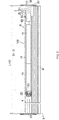
figure 3 est une vue en coupe axiale schématique partielle de l'installation domotique illustrée à lafigure 2 comprenant un dispositif d'enroulement conforme à un mode de réalisation de l'invention ; - la
figure 4 est une vue en perspective partielle du dispositif d'enroulement illustré à lafigure 3 ; et - la
figure 5 est une vue en coupe axiale partielle du dispositif d'enroulement illustré à lafigure 4 . - On va décrire tout d'abord, en référence aux
figures 1 et 2 , une installation domotique conforme à l'invention et installée dans un bâtiment comportant une ouverture 1, fenêtre ou porte, équipée d'un écran 2 appartenant à un dispositif d'occultation 3, en particulier un volet roulant motorisé. - Le dispositif d'occultation 3 peut être un volet roulant, un store en toile ou avec des lames orientables, ou encore un portail roulant. Bien entendu, la présente invention s'applique à tous les types de dispositif d'occultation.
- On va décrire, en référence aux
figures 1 et 2 , un volet roulant conforme à un mode de réalisation de l'invention. - L'écran 2 du dispositif d'occultation 3 est enroulé sur un tube d'enroulement 4 entraîné par un dispositif d'entraînement motorisé 5 et mobile entre une position enroulée, en particulier haute, et une position déroulée, en particulier basse.
- Le dispositif d'entraînement motorisé 5 comprend un actionneur électromécanique 11, en particulier de type tubulaire, permettant de mettre en rotation le tube d'enroulement 4, de sorte à dérouler ou enrouler l'écran 2 du dispositif d'occultation 3.
- Le dispositif d'occultation 3 comprend le tube d'enroulement 4 pour enrouler l'écran 2, où, dans l'état monté, l'actionneur électromécanique 11 est inséré dans le tube d'enroulement 4.
- L'écran 2 mobile du dispositif d'occultation 3 est un écran de fermeture, d'occultation et/ou de protection solaire, s'enroulant sur le tube d'enroulement 4 dont le diamètre intérieur est sensiblement équivalent au diamètre externe de l'actionneur électromécanique 11, de sorte que l'actionneur électromécanique 11 peut être inséré dans le tube d'enroulement 4 lors de l'assemblage du dispositif d'occultation 3.
- De manière connue, un volet roulant 3 comporte un tablier comprenant des lames horizontales articulées les unes aux autres, formant l'écran 2 du volet roulant 3, et guidées par deux glissières latérales 6. Ces lames sont jointives lorsque le tablier 2 du volet roulant 3 atteint sa position basse déroulée.
- Dans le cas d'un volet roulant, la position haute enroulée correspond à la mise en appui d'une lame d'extrémité finale 8 en forme de L du tablier 2 du volet roulant 3 contre un bord d'un coffre 9 du volet roulant 3, et la position basse déroulée correspond à la mise en appui de la lame d'extrémité finale 8 du tablier 2 du volet roulant 3 contre un seuil 7 de l'ouverture 1.
- La première lame du volet roulant 3, opposée à la lame d'extrémité, est reliée au tube d'enroulement 4 au moyen d'au moins une articulation 10.
- Le tube d'enroulement 4 est disposé à l'intérieur du coffre 9 du volet roulant 3. Le tablier 2 du volet roulant 3 s'enroule et se déroule autour du tube d'enroulement 4 et est logé au moins en partie à l'intérieur du coffre 9.
- De manière générale, le coffre 9 est disposé au-dessus de l'ouverture 1, ou encore en partie supérieure de l'ouverture 1.
- Le dispositif d'entraînement motorisé 5 est commandé par une unité de commande. L'unité de commande peut être, par exemple, une unité de commande locale 12, où l'unité de commande locale 12 peut être reliée en liaison filaire ou non filaire avec une unité de commande centrale 13. L'unité de commande centrale 13 pilote l'unité de commande locale 12, ainsi que d'autres unités de commande locales similaires et réparties dans le bâtiment.
- L'unité de commande centrale 13 peut être en communication avec une station météorologique déportée à l'extérieur du bâtiment, incluant, notamment, un ou plusieurs capteurs pouvant être configurés pour déterminer, par exemple, une température, une luminosité, ou encore une vitesse de vent.
- Une télécommande 14, pouvant être un type d'unité de commande locale, et pourvue d'un clavier de commande, qui comprend des moyens de sélection et d'affichage, permet, en outre, à un utilisateur d'intervenir sur l'actionneur électromécanique 11 et/ou l'unité de commande centrale 13.
- Le dispositif d'entraînement motorisé 5 est, de préférence, configuré pour exécuter les commandes de déroulement ou d'enroulement de l'écran 2 du dispositif d'occultation 3, pouvant être émises, notamment, par la télécommande 14.
- L'actionneur électromécanique 11 comprend un moteur électrique 16. Le moteur électrique 16 comprend un rotor et un stator, non représentés et positionnés de manière coaxiale autour d'un axe de rotation X qui est également l'axe de rotation du tube d'enroulement 4 en configuration montée du dispositif d'entraînement motorisé 5.
- Des moyens de commande de l'actionneur électromécanique 11, permettant le déplacement de l'écran 2 du dispositif d'occultation 3, sont constitués par au moins une unité électronique de contrôle 15. Cette unité électronique de contrôle 15 est apte à mettre en fonctionnement le moteur électrique 16 de l'actionneur électromécanique 11, et, en particulier, permettre l'alimentation en énergie électrique du moteur électrique 16.
- Ainsi, l'unité électronique de contrôle 15 commande, notamment, le moteur électrique 16, de sorte à ouvrir ou fermer l'écran 2, comme décrit précédemment.
- L'unité électronique de contrôle 15 comprend également un module de réception d'ordres, en particulier d'ordres radioélectriques émis par un émetteur d'ordres, tel que la télécommande 14 destinée à commander l'actionneur électromécanique 11.
- Le module de réception d'ordres peut également permettre la réception d'ordres transmis par des moyens filaires.
- Ici, et comme visible uniquement à la
figure 3 , l'unité électronique de contrôle 15 est disposée à l'intérieur d'un carter 17 de l'actionneur électromécanique 11. - Les moyens de commande de l'actionneur électromécanique 11 comprennent des moyens matériels et/ou logiciels.
- A titre d'exemple nullement limitatif, les moyens matériels peuvent comprendre au moins un microcontrôleur.
- On va décrire à présent, plus en détail et en référence aux
figures 3 à 5 , un dispositif d'enroulement 100 conforme à un mode de réalisation de l'invention et appartenant à l'installation domotique desfigures 1 et 2 . - L'actionneur électromécanique 11 est alimenté en énergie électrique par un réseau d'alimentation électrique du secteur, ou encore au moyen d'une batterie, pouvant être rechargée, par exemple, par un panneau photovoltaïque. L'actionneur électromécanique 11 permet de déplacer l'écran 2 du dispositif d'occultation 3.
- Ici, l'actionneur électromécanique 11 comprend un câble d'alimentation électrique 18 permettant son alimentation en énergie électrique depuis le réseau d'alimentation électrique du secteur.
- Le carter 17 de l'actionneur électromécanique 11 est, préférentiellement, de forme cylindrique.
- Dans un mode de réalisation, le carter 17 peut être réalisé dans un matériau métallique. La matière du carter de l'actionneur électromécanique n'est nullement limitative et peut, en variante, être différente ; en particulier il peut s'agir de matière plastique.
- L'actionneur électromécanique 11 comprend également un dispositif de réduction à engrenages 19 et un arbre de sortie 20.
- L'actionneur électromécanique 11 peut également comprendre un dispositif de détection de fin de course et/ou d'obstacle, pouvant être mécanique ou électronique.
- Avantageusement, le moteur électrique 16 et le dispositif de réduction à engrenages 19 sont disposés à l'intérieur du carter 17 de l'actionneur électromécanique 11.
- L'arbre de sortie 20 de l'actionneur électromécanique 11 est disposé à l'intérieur du tube d'enroulement 4, et au moins en partie à l'extérieur du carter 17 de l'actionneur électromécanique 11.
- L'arbre de sortie 20 de l'actionneur électromécanique 11 est accouplé, par un moyen de liaison 22, au tube d'enroulement 4, en particulier un moyen de liaison en forme de roue.
- En outre, le moyen de liaison 22 peut être fixé sur le tube d'enroulement 4 au moyen d'un élément de fixation, tel que par exemple une vis de fixation ou un rivet, suite au positionnement de l'actionneur électromécanique 11 à l'intérieur du tube d'enroulement 4.
- L'actionneur électromécanique 11 comprend également un élément d'obturation 21 d'une extrémité du carter 17.
- Ici, le carter 17 de l'actionneur électromécanique 11 est fixé à un support 23, en particulier une joue, du coffre 9 du dispositif d'occultation 3 au moyen de l'élément d'obturation 21 formant un support de couple, en particulier une tête d'obturation et de reprise de couple. Dans un tel cas où l'élément d'obturation 21 forme un support de reprise de couple, l'élément d'obturation 21 est également appelé un point fixe de l'actionneur électromécanique 11.
- Le dispositif d'enroulement 100 comprend, en particulier, le tube d'enroulement 4, l'actionneur électromécanique 11 de type tubulaire et un manchon creux 24. Le manchon creux 24 est disposé à l'une des extrémités du tube d'enroulement 4 et à l'intérieur du tube d'enroulement 4.
- Ici, le manchon creux 24 est disposé à l'extrémité 4a du tube d'enroulement 4 au niveau de laquelle l'actionneur électromécanique tubulaire 11 est introduit dans le tube d'enroulement 4, lors de l'assemblage du dispositif d'enroulement 100.
- L'autre extrémité 4b du tube d'enroulement 4 est reliée fonctionnellement à un support 23, en particulier une joue, du coffre 9 du dispositif d'occultation 3 au moyen d'un palier non représenté, de sorte à permettre le mouvement de rotation du tube d'enroulement 4 autour de l'axe de rotation X.
- On note L100 la longueur du dispositif d'enroulement 100, mesurée parallèlement à l'axe de rotation X, entre les supports 23.
- Le manchon creux 24 présente, sur une partie L1 de sa longueur L mesurée parallèlement à l'axe de rotation X, une section extérieure correspondant à la section intérieure du tube d'enroulement 4. Par « correspondant », on entend que la section extérieure du manchon creux 24 présente une géométrie semblable à la section intérieure du tube d'enroulement 4, tout en étant de forme convexe, alors que la section intérieure du tube d'enroulement 4 est de forme concave.
- L'actionneur électromécanique tubulaire 11, en particulier le corps de celui-ci, est inséré à l'intérieur du manchon creux 24.
- Ici, le manchon creux 24 est réalisé sous la forme d'une bague. Le corps de l'actionneur électromécanique tubulaire 11 est inséré à l'intérieur du manchon creux 24. Et le manchon creux 24 est inséré dans le tube d'enroulement 4.
- Ici, seule une partie de l'actionneur électromécanique tubulaire 11 est disposée à l'intérieur du manchon creux 24.
- Le dispositif d'enroulement 100 comprend des éléments de fixation 25a, 25b coopérant avec le manchon creux 24 et le tube d'enroulement 4, de sorte à bloquer en translation le manchon creux 24 par rapport au tube d'enroulement 4. Et l'actionneur électromécanique tubulaire 11 est monté coulissant dans le manchon creux 24, de sorte à ajuster la longueur L100 du dispositif d'enroulement 100 de manière télescopique.
- Ainsi, le manchon creux 24 est bloqué en translation sur le tube d'enroulement 4 et l'actionneur électromécanique tubulaire 11 est libre en translation et en rotation par rapport au manchon creux 24, de sorte à pouvoir ajuster la longueur L100 du dispositif d'enroulement 100 de manière télescopique par le coulissement de l'actionneur électromécanique tubulaire 11 dans le manchon creux 24 et, ainsi, à l'intérieur du tube d'enroulement 4.
- De cette manière, le coulissement de l'actionneur électromécanique tubulaire 11 à l'intérieur du manchon creux 24, permettant l'ajustement en longueur du dispositif d'enroulement 100 de manière télescopique, est mis en oeuvre sans contraintes liées à la déformation de la découpe du tube d'enroulement 4, puisque le manchon creux 24 est inséré et maintenu en position à l'intérieur du tube d'enroulement 4, de sorte à rattraper les déformations du tube d'enroulement 4, et sert de palier entre l'actionneur électromécanique tubulaire 11 et le tube d'enroulement 4.
- L'insertion du manchon creux 24 à l'intérieur et à l'extrémité 4a du tube d'enroulement 4, qui est destinée à accueillir l'actionneur électromécanique tubulaire 11, permet également de protéger un utilisateur manipulant le tube d'enroulement 4 contre des risques de coupure liés aux bavures engendrées par la découpe du tube d'enroulement 4.
- En outre, le jeu fonctionnel entre le manchon creux 24 et l'actionneur électromécanique tubulaire 11 est réduit, puisque ces deux éléments ne présentent pas de déformation, suite à leur fabrication pour permettre l'assemblage du dispositif d'enroulement 100. Le jeu fonctionnel entre le manchon creux 24 et l'actionneur électromécanique tubulaire 11 est minimisé, de sorte à garantir l'alignement des axes longitudinaux de l'actionneur électromécanique tubulaire 11, du manchon creux 24 et du tube d'enroulement 4, lors du déplacement de l'actionneur électromécanique tubulaire 11 par rapport au manchon creux 24 et au tube d'enroulement 4.
- Par conséquent, le coulissement de l'actionneur électromécanique tubulaire 11 à l'intérieur du manchon creux 24 bloqué en translation sur le tube d'enroulement 4 permet l'ajustement en longueur du dispositif d'enroulement 100 de manière télescopique, tout en limitant les efforts mécaniques et les frottements entre le tube d'enroulement 4, le manchon creux 24 et l'actionneur électromécanique tubulaire 11, lesquels constituent ensemble le dispositif d'enroulement 100.
- Le dispositif d'enroulement 100 peut, ainsi, prendre différentes longueurs L100, par l'intermédiaire du coulissement de l'actionneur électromécanique tubulaire 11 à l'intérieur du manchon creux 24 bloqué en translation sur le tube d'enroulement 4, de sorte à s'adapter à différentes largeurs d'ouvertures 1 à obturer par l'écran enroulable 2 et/ou à différentes largeurs de coffres 9 à l'intérieur desquels est disposé le dispositif d'enroulement 100, entre les supports 23.
- Par ailleurs, la longueur L du manchon creux 24 est minimisée, de sorte à réduire les coûts d'obtention de celui-ci et, par conséquent, du dispositif d'enroulement 100, et à minimiser les coûts d'investissement pour fabriquer le manchon creux 24.
- Dans une configuration assemblée de l'actionneur électromécanique 11 à l'intérieur du manchon creux 24 bloqué en translation sur le tube d'enroulement 4, ou autrement dit suite à l'installation de l'ensemble formé par l'actionneur électromécanique 11, le manchon creux 24 et le tube d'enroulement 4 dans le coffre 9, l'actionneur électromécanique 11 est positionné par rapport au manchon creux 24 et au tube d'enroulement 4 par coulissement de l'actionneur électromécanique 11 dans le manchon creux 24, de sorte à coopérer avec le support 23 du coffre 9.
- Ainsi, la zone de contact entre le carter 17 de l'actionneur électromécanique 11 et le manchon creux 24, servant de palier, est dépendante de la position de l'actionneur électromécanique 11 par rapport au tube d'enroulement 4, suite à l'assemblage de l'actionneur électromécanique 11 avec le support 23 du coffre 9.
- Dans la configuration assemblée de l'actionneur électromécanique 11 à l'intérieur du manchon creux 24 bloqué en translation sur le tube d'enroulement 4, le tube d'enroulement 4 est maintenu en rotation et en translation sur l'arbre de sortie 20 de l'actionneur électromécanique 11 par l'intermédiaire de l'élément de liaison 22. Et le carter 17 de l'actionneur électromécanique 11 est libre en rotation à l'intérieur du manchon creux 24.
- Le tube d'enroulement 4 de l'écran enroulable 2 de l'installation domotique de fermeture ou de protection solaire coopère avec le manchon creux 24, le manchon creux 24 s'insérant à l'intérieur du tube d'enroulement 4 et au niveau de l'extrémité 4a du tube d'enroulement 4 qui est destinée à accueillir l'actionneur électromécanique tubulaire 11. Le corps de l'actionneur électromécanique tubulaire 11 peut coulisser à l'intérieur du manchon creux 24, de sorte à fournir un dispositif d'enroulement 100 s'adaptant à différentes largeurs de coffres 9, tout en utilisant le même tube d'enroulement 4.
- Un tel dispositif d'enroulement 100 permet de limiter le nombre de références de tubes d'enroulement 4 en stock ayant des longueurs différentes.
- En pratique, le manchon creux 24 est fixé au tube d'enroulement 4 par les éléments de fixation 25a, 25b au niveau de l'extrémité 4a du tube d'enroulement 4 recevant l'actionneur électromécanique tubulaire 11, autrement dit à l'extrémité opposée à l'extrémité 4b du tube d'enroulement 4 reliée fonctionnellement au moyen d'un palier au support 23 du coffre 9, de sorte à créer une liaison pivot.
- Ainsi, la partie télescopique du dispositif d'enroulement 100 est réalisée par le déplacement et le positionnement de l'actionneur électromécanique tubulaire 11 à l'intérieur du manchon creux 24, le manchon creux 24 étant fixé au tube d'enroulement 4 par les éléments de fixation 25a, 25b.
- De cette manière, l'utilisation du corps de l'actionneur électromécanique tubulaire 11, en particulier du carter 17 de l'actionneur électromécanique tubulaire 11, pour réaliser la partie télescopique du dispositif d'enroulement 100 permet de minimiser les coûts d'obtention du dispositif d'enroulement 100.
- Avantageusement, la section extérieure de la partie L1 de la longueur L du manchon creux 24 est en contact direct avec la section intérieure du tube d'enroulement 4.
- Ainsi, le manchon creux 24 et le tube d'enroulement 4 sont accouplés directement ensemble, autrement dit sans éléments intermédiaires, de sorte à minimiser les coûts d'obtention du dispositif d'enroulement 100.
- Préférentiellement, la partie L1 de la longueur L du manchon creux 24 présentant une section extérieure correspondant à la section intérieure du tube d'enroulement 4 est disposée intégralement à l'intérieur du tube d'enroulement 4.
- Ainsi, le manchon creux 24 est maintenu à l'intérieur du tube d'enroulement 4 par les éléments de fixation 25a, 25b et sur l'ensemble de la partie L1 de sa longueur L coopérant avec le tube d'enroulement 4, de sorte à limiter les efforts mécaniques entre le tube d'enroulement 4 et le manchon creux 24, suite à l'insertion de l'actionneur électromécanique tubulaire 11 dans le manchon creux 24.
- Avantageusement, le corps de l'actionneur électromécanique tubulaire 11 présente, sur au moins une partie D1 de sa longueur D mesurée parallèlement à l'axe de rotation X, une section extérieure correspondant à la section intérieure du manchon creux 24, où la section extérieure du corps de l'actionneur électromécanique tubulaire 11 et la section intérieure du manchon creux 24 sont circulaires, de sorte à permettre un mouvement de rotation du tube d'enroulement 4 par rapport au corps de l'actionneur électromécanique tubulaire 11 suivant l'axe de rotation du tube d'enroulement 4, qui est confondu avec l'axe de rotation X en configuration montée du dispositif d'enroulement 100. Par « correspondant », on entend que la section extérieure de l'actionneur électromécanique 11 présente une géométrie semblable à la section intérieure du manchon creux 24, tout en étant de forme convexe, alors que la section intérieure du manchon creux est de forme concave.
- Ainsi, le tube d'enroulement 4 peut être entraîné en rotation autour de l'axe de rotation X et, en particulier, autour du corps de l'actionneur électromécanique tubulaire 11, lors de l'enroulement et du déroulement de l'écran 2. Le mouvement de rotation du tube d'enroulement 4 est généré par le moteur électrique 16 de l'actionneur électromécanique tubulaire 11 entraînant en rotation l'arbre de sortie 20 de l'actionneur électromécanique tubulaire 11, puis le moyen de liaison 22 accouplé au tube d'enroulement 4.
- Ici, le corps de l'actionneur électromécanique tubulaire 11 correspond au carter 17.
- En outre, la longueur D1 du corps de l'actionneur électromécanique tubulaire 11 ayant une section extérieure correspondant à la section intérieure du manchon creux 24 est égale à la longueur totale D du corps de l'actionneur électromécanique tubulaire 11.
- Préférentiellement, la section extérieure du manchon creux 24 et la section intérieure du tube d'enroulement 4 présentent des créneaux 27, de sorte à rendre solidaire en rotation le manchon creux 24 par rapport au tube d'enroulement 4. Ainsi, le manchon creux 24 est bloqué en rotation sur le tube d'enroulement 4.
- Les créneaux 27 de la section extérieure du manchon creux 24 et de la section intérieure du tube d'enroulement 4 forment des rainures et des nervures, s'étendant suivant la longueur de leur corps, en particulier suivant leur axe longitudinal, qui est confondu avec l'axe de rotation X en configuration montée du dispositif d'enroulement 100.
- Préférentiellement, les créneaux 27 de la section extérieure du manchon creux 24 sont complémentaires des créneaux de la section intérieure du tube d'enroulement 4.
- Ainsi, le blocage en rotation du manchon creux 24 par rapport au tube d'enroulement 4 est réalisé au moyen des créneaux respectifs, de sorte à éviter le frottement du manchon creux 24 sur le tube d'enroulement 4.
- De cette manière, le blocage en rotation du manchon creux 24 par rapport au tube d'enroulement 4 permet d'éviter l'usure du manchon creux 24 inséré à l'intérieur du tube d'enroulement 4.
- Dans un mode de réalisation, le tube d'enroulement 4 est réalisé à partir d'une tôle métallique pliée et les deux extrémités de cette tôle sont reliées par la formation d'un joint plié. Et la section du tube d'enroulement 4 est de forme cannelée.
- En pratique, le manchon creux 24 comprend une butée 26 à l'une de ses deux extrémités, de sorte à bloquer en translation le manchon creux 24 par rapport à l'extrémité 4a du tube d'enroulement 4, au travers de laquelle le manchon creux 24 est inséré dans le tube d'enroulement 4, dans le sens d'introduction du manchon creux 24 à l'intérieur du tube d'enroulement 4.
- Ainsi, la butée 26 du manchon creux 24 permet de garantir un positionnement du manchon creux 24 par rapport à l'extrémité 4a du tube d'enroulement 4, suivant la direction de l'axe de rotation du tube d'enroulement 4, qui est confondu avec l'axe de rotation X en configuration montée du dispositif d'enroulement 100.
- En outre, la butée 26 du manchon creux 24 permet d'éviter que le manchon creux 24 n'entre trop dans le tube d'enroulement 4, en particulier lors de l'introduction de l'actionneur électromécanique tubulaire 11 dans le manchon creux 24, afin d'éviter le retrait du manchon creux 24 disposé autour du carter 17 de l'actionneur électromécanique 11, dans la configuration montée du dispositif d'enroulement 100, et de garantir le maintien en position de l'actionneur électromécanique tubulaire 11 à l'intérieur du tube d'enroulement 4 par le manchon creux 24.
- Avantageusement, le manchon creux 24 présente, au niveau de sa butée 26, une section extérieure supérieure ou égale à la section extérieure du tube d'enroulement 4. Par « supérieure ou égale », on entend que la section de la butée 26 s'étend, par rapport à l'axe de rotation X, à une distance radiale supérieure ou égale à la distance radiale maximale à laquelle s'étend la surface extérieure du tube d'enroulement 4.
- Ici, la butée du manchon creux 24 est réalisée sous la forme d'une collerette, en particulier de forme cylindrique.
- Avantageusement, seule la partie du manchon creux 24 constituant la butée 26 est disposée à l'extérieur du tube d'enroulement 4.
- Ainsi, le manchon creux 24 est disposé quasi-intégralement à l'intérieur du tube d'enroulement 4, de sorte à limiter les efforts mécaniques entre le tube d'enroulement 4 et le manchon creux 24, suite à l'insertion de l'actionneur électromécanique tubulaire 11 dans le manchon creux 24, et à minimiser les coûts d'obtention de celui-ci.
- Préférentiellement, le manchon creux 24 est en matière plastique.
- A titre d'exemples nullement limitatifs, la matière plastique du manchon creux 24 peut être du polyoxyméthylène, encore appelé « POM », ou de l'acrylonitrile butadiène styrène, encore appelé « ABS ».
- Les éléments de fixation 25a, 25b du manchon creux 24 et du tube d'enroulement 4 permettent de bloquer en translation le manchon creux 24 par rapport au tube d'enroulement 4, afin d'éviter qu'un coulissement axial du manchon creux 24 par rapport au tube d'enroulement 4 ne se produise de manière intempestive.
- De cette manière, l'actionneur électromécanique tubulaire 11 peut coulisser à l'intérieur du manchon creux 24 et donc du tube d'enroulement 4, sans risque de mise en appui de l'actionneur électromécanique tubulaire 11 avec la face interne du tube d'enroulement 4 par un désengagement du manchon creux 24 par rapport au tube d'enroulement 4.
- Préférentiellement, les éléments de fixation 25a, 25b sont intégrés dans le manchon creux 24 et le tube d'enroulement 4.
- Ainsi, le manchon creux 24 et le tube d'enroulement 4 sont fixés ensemble directement, autrement dit sans éléments intermédiaires, de sorte à minimiser les coûts d'obtention du dispositif d'enroulement 100.
- Dans le mode de réalisation illustré à la
figure 4 , les éléments de fixation axiale 25a, 25b du manchon creux 24 et du tube d'enroulement 4 sont des éléments d'encliquetage. L'élément de fixation 25a du manchon creux 24 comprend une nervure. L'élément de fixation 25 du tube d'enroulement 4 comprend une encoche. La nervure 25a du manchon creux 24 coopère avec l'encoche 25b du tube d'enroulement 4, suite à l'insertion du manchon creux 24 dans le tube d'enroulement 4, en particulier, suite à la mise en appui de la butée 26 du manchon creux 24 avec l'extrémité 4a du tube d'enroulement 4. - Dans un autre mode de réalisation, non représenté, les éléments de fixation axiale du manchon creux 24 et du tube d'enroulement 4 sont des éléments de vissage. Dans ce cas, l'élément de fixation du manchon creux 24 comprend un trou de vissage. L'élément de fixation du tube d'enroulement 4 comprend un trou de passage. Une vis de fixation passe au travers du trou de passage du tube d'enroulement 4 et est vissée dans le trou de vissage du manchon creux 24.
- Bien entendu, le type des éléments de fixation axiale du manchon creux 24 et du tube d'enroulement 4 n'est nullement limitatif, et peut être différent. Il peut, en particulier, comprendre des éléments de rivetage.
- En outre, le nombre des éléments de fixation du dispositif d'enroulement 100 coopérant avec le manchon creux 24 et le tube d'enroulement 4 n'est nullement limitatif. Le dispositif d'enroulement 100 peut comprendre plusieurs sous-ensembles de fixation axiale du manchon creux 24 et du tube d'enroulement 4.
- En variante, les éléments de fixation 25a, 25b du dispositif d'enroulement 100 coopérant avec le manchon creux 24 et le tube d'enroulement 4 sont réalisés par correspondance de forme du manchon creux 24 et du tube d'enroulement 4, de sorte à garantir un effort de frottement minimal entre le manchon creux 24 et le tube d'enroulement 4.
- Avantageusement, le manchon creux 24 présente une longueur L comprise dans une plage s'étendant entre 20 millimètres et 50 millimètres.
- Et l'actionneur électromécanique tubulaire 11 est engagé dans le manchon creux 24 sur une longueur minimale de l'ordre de 40 millimètres à l'intérieur du tube d'enroulement 4, de sorte à garantir la fiabilité du dispositif d'enroulement 100, lors de l'entraînement en rotation de l'écran 2 par l'actionneur électromécanique tubulaire 11.
- Grâce à la présente invention, le manchon creux est bloqué en translation sur le tube d'enroulement et l'actionneur électromécanique tubulaire est libre en translation et en rotation par rapport au manchon creux, de sorte à pouvoir ajuster la longueur du dispositif d'enroulement de manière télescopique par le coulissement de l'actionneur électromécanique tubulaire dans le manchon creux et, ainsi, à l'intérieur du tube d'enroulement.
- Bien entendu, de nombreuses modifications peuvent être apportées aux exemples de réalisation décrits précédemment sans sortir du cadre de l'invention.
- En outre, les modes de réalisation et variantes envisagés peuvent être combinés pour générer de nouveaux modes de réalisation de l'invention.
Claims (10)
- Dispositif d'enroulement (100) pour un écran enroulable (2) d'une installation domotique de fermeture ou de protection solaire, le dispositif d'enroulement (100) comprenant :- un tube d'enroulement (4),- un manchon creux (24),- un actionneur électromécanique tubulaire (11),• où le manchon creux (24) est disposé à l'une des extrémités du tube d'enroulement (4) et à l'intérieur du tube d'enroulement (4),• où le manchon creux (24) présente, sur une partie (L1) de sa longueur (L), une section extérieure correspondant à la section intérieure du tube d'enroulement (4), et• où l'actionneur électromécanique tubulaire (11) est inséré à l'intérieur du manchon creux (24),caractérisé en ce que le dispositif d'enroulement (100) comprend des éléments de fixation (25a, 25b) coopérant avec le manchon creux (24) et le tube d'enroulement (4), de sorte à bloquer en translation le manchon creux (24) par rapport au tube d'enroulement (4), et
en ce que l'actionneur électromécanique tubulaire (11) est monté coulissant dans le manchon creux (24), de sorte à ajuster la longueur (L100) du dispositif d'enroulement (100) de manière télescopique. - Dispositif d'enroulement (100) pour un écran enroulable (2) d'une installation domotique de fermeture ou de protection solaire selon la revendication 1, caractérisé en ce que le corps de l'actionneur électromécanique tubulaire (11) présente, sur au moins une partie (D1) de sa longueur (D), une section extérieure correspondant à la section intérieure du manchon creux (24), où la section extérieure du corps de l'actionneur électromécanique tubulaire (11) et la section intérieure du manchon creux (24) sont circulaires, de sorte à permettre un mouvement de rotation du tube d'enroulement (4) par rapport au corps de l'actionneur électromécanique tubulaire (11) suivant un axe de rotation (X) du tube d'enroulement (4).
- Dispositif d'enroulement (100) pour un écran enroulable (2) d'une installation domotique de fermeture ou de protection solaire selon la revendication 1 ou la revendication 2, caractérisé en ce que la section extérieure du manchon creux (24) et la section intérieure du tube d'enroulement (4) présentent des créneaux (27), de sorte à rendre solidaire en rotation le manchon creux (24) par rapport au tube d'enroulement (4).
- Dispositif d'enroulement (100) pour un écran enroulable (2) d'une installation domotique de fermeture ou de protection solaire selon la revendication 3, caractérisé en ce que les créneaux (27) de la section extérieure du manchon creux (24) sont complémentaires des créneaux de la section intérieure du tube d'enroulement (4).
- Dispositif d'enroulement (100) pour un écran enroulable (2) d'une installation domotique de fermeture ou de protection solaire selon l'une quelconque des revendications 1 à 4, caractérisé en ce que le manchon creux (24) comprend une butée (26) à l'une de ses deux extrémités, de sorte à bloquer en translation le manchon creux (24) par rapport à l'extrémité du tube d'enroulement (4), au travers de laquelle le manchon creux (24) est inséré dans le tube d'enroulement (4), dans un sens d'introduction du manchon creux (24) à l'intérieur du tube d'enroulement (4).
- Dispositif d'enroulement (100) pour un écran enroulable (2) d'une installation domotique de fermeture ou de protection solaire selon l'une quelconque des revendications 1 à 5, caractérisé en ce que le manchon creux (24) est en matière plastique.
- Dispositif d'enroulement (100) pour un écran enroulable (2) d'une installation domotique de fermeture ou de protection solaire selon l'une quelconque des revendications 1 à 6, caractérisé en ce que la partie (L1) de la longueur (L) du manchon creux (24) présentant une section extérieure correspondant à la section intérieure du tube d'enroulement (4) est disposée intégralement à l'intérieur du tube d'enroulement (4).
- Dispositif d'enroulement (100) pour un écran enroulable (2) d'une installation domotique de fermeture ou de protection solaire selon l'une quelconque des revendications 1 à 7, caractérisé en ce que le manchon creux (24) est fixé au tube d'enroulement (4) par les éléments de fixation (25a, 25b) au niveau de l'extrémité (4a) du tube d'enroulement (4) recevant l'actionneur électromécanique tubulaire (11).
- Dispositif d'enroulement (100) pour un écran enroulable (2) d'une installation domotique de fermeture ou de protection solaire selon l'une quelconque des revendications 1 à 8, caractérisé en ce que les éléments de fixation (25a, 25b) sont intégrés dans le manchon creux (24) et le tube d'enroulement (4).
- Installation domotique de fermeture ou de protection solaire comprenant un écran (2) enroulable au moyen d'un dispositif d'enroulement (100) sur un tube d'enroulement (4) entraîné en rotation par un actionneur électromécanique tubulaire (11), caractérisée en ce que le dispositif d'enroulement (100) est conforme à l'une quelconque des revendications 1 à 9.
Applications Claiming Priority (1)
| Application Number | Priority Date | Filing Date | Title |
|---|---|---|---|
| FR1460829A FR3028284B1 (fr) | 2014-11-07 | 2014-11-07 | Dispositif d'enroulement pour un ecran enroulable d'une installation domotique de fermeture ou de protection solaire |
Publications (2)
| Publication Number | Publication Date |
|---|---|
| EP3020910A1 true EP3020910A1 (fr) | 2016-05-18 |
| EP3020910B1 EP3020910B1 (fr) | 2017-08-30 |
Family
ID=52450369
Family Applications (1)
| Application Number | Title | Priority Date | Filing Date |
|---|---|---|---|
| EP15193472.6A Not-in-force EP3020910B1 (fr) | 2014-11-07 | 2015-11-06 | Dispositif d'enroulement pour un écran enroulable d'une installation domotique de fermeture ou de protection solaire |
Country Status (2)
| Country | Link |
|---|---|
| EP (1) | EP3020910B1 (fr) |
| FR (1) | FR3028284B1 (fr) |
Cited By (1)
| Publication number | Priority date | Publication date | Assignee | Title |
|---|---|---|---|---|
| FR3055652A1 (fr) * | 2016-09-08 | 2018-03-09 | Bubendorff | Dispositif d'enroulement/deroulement d'un ecran par exemple du type volet roulant. |
Citations (4)
| Publication number | Priority date | Publication date | Assignee | Title |
|---|---|---|---|---|
| FR2766806A3 (fr) | 1997-07-31 | 1999-02-05 | Somfy | Tube d'enroulement telescopique |
| EP1635031A2 (fr) * | 2004-09-08 | 2006-03-15 | Deprat Jean SA | Dispositif écran ou de protection pour ouverture, tel que notamment un store ou encore un volet roulant, comprenant un tube d'enroulement |
| WO2009047458A2 (fr) * | 2007-09-20 | 2009-04-16 | Somfy Sas | Dispositif d'entrainement en rotation et de support d'un tube d'enroulement et installation domotique comprenant un tel dispositif |
| EP2208849A1 (fr) | 2009-01-15 | 2010-07-21 | Deprat Jean SA | Arbre d'enroulement motorisé, notamment pour un dispositif de fermeture ou d'occultation |
-
2014
- 2014-11-07 FR FR1460829A patent/FR3028284B1/fr active Active
-
2015
- 2015-11-06 EP EP15193472.6A patent/EP3020910B1/fr not_active Not-in-force
Patent Citations (4)
| Publication number | Priority date | Publication date | Assignee | Title |
|---|---|---|---|---|
| FR2766806A3 (fr) | 1997-07-31 | 1999-02-05 | Somfy | Tube d'enroulement telescopique |
| EP1635031A2 (fr) * | 2004-09-08 | 2006-03-15 | Deprat Jean SA | Dispositif écran ou de protection pour ouverture, tel que notamment un store ou encore un volet roulant, comprenant un tube d'enroulement |
| WO2009047458A2 (fr) * | 2007-09-20 | 2009-04-16 | Somfy Sas | Dispositif d'entrainement en rotation et de support d'un tube d'enroulement et installation domotique comprenant un tel dispositif |
| EP2208849A1 (fr) | 2009-01-15 | 2010-07-21 | Deprat Jean SA | Arbre d'enroulement motorisé, notamment pour un dispositif de fermeture ou d'occultation |
Cited By (2)
| Publication number | Priority date | Publication date | Assignee | Title |
|---|---|---|---|---|
| FR3055652A1 (fr) * | 2016-09-08 | 2018-03-09 | Bubendorff | Dispositif d'enroulement/deroulement d'un ecran par exemple du type volet roulant. |
| EP3293344A1 (fr) * | 2016-09-08 | 2018-03-14 | BUBENDORFF Société Anonyme | Dispositif d'enroulement/déroulement d'un volet roulant |
Also Published As
| Publication number | Publication date |
|---|---|
| FR3028284B1 (fr) | 2016-11-18 |
| FR3028284A1 (fr) | 2016-05-13 |
| EP3020910B1 (fr) | 2017-08-30 |
Similar Documents
| Publication | Publication Date | Title |
|---|---|---|
| EP2957705B1 (fr) | Actionneur électromécanique et installation domotique comprenant un tel actionneur | |
| EP3341550B1 (fr) | Installation domotique de fermeture ou de protection solaire et procédé de recharge d'une batterie pour une telle installation | |
| FR3037987A1 (fr) | Dispositif d'enroulement pour un ecran enroulable et installation domotique de fermeture ou de protection solaire incorporant un tel dispositif | |
| EP3717728B1 (fr) | Actionneur électromécanique et installation domotique comprenant un tel actionneur | |
| EP3167140B1 (fr) | Actionneur electromecanique et installation domotique comprenant un tel actionneur electromecanique | |
| EP3803021B1 (fr) | Dispositif d'occultation pour une installation domotique de fermeture ou de protection solaire d'un batiment et installation domotique associee | |
| EP3341551B1 (fr) | Installation domotique de fermeture ou de protection solaire et procédé de recharge d'une batterie pour une telle installation | |
| EP3830374B1 (fr) | Module mécanique de filtrage de vibrations, actionneur électromécanique comprenant un tel module mécanique de filtrage de vibrations et installation de fermeture, d'occultation ou de protection solaire comprenant un tel actionneur électromécanique | |
| EP3695087B1 (fr) | Actionneur électromécanique tubulaire, installation domotique comprenant un tel actionneur et procédé d'assemblage d'un tel actionneur | |
| EP2886785B1 (fr) | Dispositif d'entraînement motorisé d'un tube d'enroulement pour un écran appartenant à un dispositif d'occultation | |
| EP3695086A1 (fr) | Actionneur électromécanique tubulaire, installation domotique comprenant un tel actionneur et procédé d'assemblage d'un tel actionneur | |
| FR3086688A1 (fr) | Actionneur electromecanique comprenant un module de filtrage de vibrations et installation de fermeture, d'occultation ou de protection solaire comprenant un tel actionneur electromecanique | |
| EP3020910B1 (fr) | Dispositif d'enroulement pour un écran enroulable d'une installation domotique de fermeture ou de protection solaire | |
| FR3096194A1 (fr) | Actionneur électromécanique et installation de fermeture, d’occultation ou de protection solaire comprenant un tel actionneur électromécanique | |
| EP3263822B1 (fr) | Installation domotique | |
| EP3821104B1 (fr) | Système d'entraînement d'un écran et installation comprenant un tel système | |
| EP3263821B1 (fr) | Installation domotique et procédé de mise en service de ladite installation | |
| EP1635031A2 (fr) | Dispositif écran ou de protection pour ouverture, tel que notamment un store ou encore un volet roulant, comprenant un tube d'enroulement | |
| EP3135852B1 (fr) | Bouchon avec un système guide-câble d'un actionneur électromécanique tubulaire pour un arbre d'enroulement |
Legal Events
| Date | Code | Title | Description |
|---|---|---|---|
| PUAI | Public reference made under article 153(3) epc to a published international application that has entered the european phase |
Free format text: ORIGINAL CODE: 0009012 |
|
| AK | Designated contracting states |
Kind code of ref document: A1 Designated state(s): AL AT BE BG CH CY CZ DE DK EE ES FI FR GB GR HR HU IE IS IT LI LT LU LV MC MK MT NL NO PL PT RO RS SE SI SK SM TR |
|
| AX | Request for extension of the european patent |
Extension state: BA ME |
|
| 17P | Request for examination filed |
Effective date: 20161103 |
|
| RBV | Designated contracting states (corrected) |
Designated state(s): AL AT BE BG CH CY CZ DE DK EE ES FI FR GB GR HR HU IE IS IT LI LT LU LV MC MK MT NL NO PL PT RO RS SE SI SK SM TR |
|
| GRAP | Despatch of communication of intention to grant a patent |
Free format text: ORIGINAL CODE: EPIDOSNIGR1 |
|
| INTG | Intention to grant announced |
Effective date: 20170329 |
|
| RIN1 | Information on inventor provided before grant (corrected) |
Inventor name: GARBY, THIERRY Inventor name: ANTHOINE, SEBASTIEN |
|
| GRAS | Grant fee paid |
Free format text: ORIGINAL CODE: EPIDOSNIGR3 |
|
| GRAA | (expected) grant |
Free format text: ORIGINAL CODE: 0009210 |
|
| RAP1 | Party data changed (applicant data changed or rights of an application transferred) |
Owner name: SOMFY ACTIVITES SA |
|
| AK | Designated contracting states |
Kind code of ref document: B1 Designated state(s): AL AT BE BG CH CY CZ DE DK EE ES FI FR GB GR HR HU IE IS IT LI LT LU LV MC MK MT NL NO PL PT RO RS SE SI SK SM TR |
|
| REG | Reference to a national code |
Ref country code: GB Ref legal event code: FG4D Free format text: NOT ENGLISH |
|
| REG | Reference to a national code |
Ref country code: CH Ref legal event code: EP |
|
| REG | Reference to a national code |
Ref country code: AT Ref legal event code: REF Ref document number: 923731 Country of ref document: AT Kind code of ref document: T Effective date: 20170915 |
|
| REG | Reference to a national code |
Ref country code: IE Ref legal event code: FG4D Free format text: LANGUAGE OF EP DOCUMENT: FRENCH |
|
| REG | Reference to a national code |
Ref country code: DE Ref legal event code: R096 Ref document number: 602015004434 Country of ref document: DE |
|
| REG | Reference to a national code |
Ref country code: FR Ref legal event code: PLFP Year of fee payment: 3 |
|
| REG | Reference to a national code |
Ref country code: NL Ref legal event code: MP Effective date: 20170830 |
|
| REG | Reference to a national code |
Ref country code: LT Ref legal event code: MG4D |
|
| REG | Reference to a national code |
Ref country code: AT Ref legal event code: MK05 Ref document number: 923731 Country of ref document: AT Kind code of ref document: T Effective date: 20170830 |
|
| PG25 | Lapsed in a contracting state [announced via postgrant information from national office to epo] |
Ref country code: LT Free format text: LAPSE BECAUSE OF FAILURE TO SUBMIT A TRANSLATION OF THE DESCRIPTION OR TO PAY THE FEE WITHIN THE PRESCRIBED TIME-LIMIT Effective date: 20170830 Ref country code: SE Free format text: LAPSE BECAUSE OF FAILURE TO SUBMIT A TRANSLATION OF THE DESCRIPTION OR TO PAY THE FEE WITHIN THE PRESCRIBED TIME-LIMIT Effective date: 20170830 Ref country code: AT Free format text: LAPSE BECAUSE OF FAILURE TO SUBMIT A TRANSLATION OF THE DESCRIPTION OR TO PAY THE FEE WITHIN THE PRESCRIBED TIME-LIMIT Effective date: 20170830 Ref country code: FI Free format text: LAPSE BECAUSE OF FAILURE TO SUBMIT A TRANSLATION OF THE DESCRIPTION OR TO PAY THE FEE WITHIN THE PRESCRIBED TIME-LIMIT Effective date: 20170830 Ref country code: NO Free format text: LAPSE BECAUSE OF FAILURE TO SUBMIT A TRANSLATION OF THE DESCRIPTION OR TO PAY THE FEE WITHIN THE PRESCRIBED TIME-LIMIT Effective date: 20171130 Ref country code: HR Free format text: LAPSE BECAUSE OF FAILURE TO SUBMIT A TRANSLATION OF THE DESCRIPTION OR TO PAY THE FEE WITHIN THE PRESCRIBED TIME-LIMIT Effective date: 20170830 |
|
| PG25 | Lapsed in a contracting state [announced via postgrant information from national office to epo] |
Ref country code: ES Free format text: LAPSE BECAUSE OF FAILURE TO SUBMIT A TRANSLATION OF THE DESCRIPTION OR TO PAY THE FEE WITHIN THE PRESCRIBED TIME-LIMIT Effective date: 20170830 Ref country code: LV Free format text: LAPSE BECAUSE OF FAILURE TO SUBMIT A TRANSLATION OF THE DESCRIPTION OR TO PAY THE FEE WITHIN THE PRESCRIBED TIME-LIMIT Effective date: 20170830 Ref country code: GR Free format text: LAPSE BECAUSE OF FAILURE TO SUBMIT A TRANSLATION OF THE DESCRIPTION OR TO PAY THE FEE WITHIN THE PRESCRIBED TIME-LIMIT Effective date: 20171201 Ref country code: IS Free format text: LAPSE BECAUSE OF FAILURE TO SUBMIT A TRANSLATION OF THE DESCRIPTION OR TO PAY THE FEE WITHIN THE PRESCRIBED TIME-LIMIT Effective date: 20171230 Ref country code: RS Free format text: LAPSE BECAUSE OF FAILURE TO SUBMIT A TRANSLATION OF THE DESCRIPTION OR TO PAY THE FEE WITHIN THE PRESCRIBED TIME-LIMIT Effective date: 20170830 Ref country code: BG Free format text: LAPSE BECAUSE OF FAILURE TO SUBMIT A TRANSLATION OF THE DESCRIPTION OR TO PAY THE FEE WITHIN THE PRESCRIBED TIME-LIMIT Effective date: 20171130 |
|
| PG25 | Lapsed in a contracting state [announced via postgrant information from national office to epo] |
Ref country code: NL Free format text: LAPSE BECAUSE OF FAILURE TO SUBMIT A TRANSLATION OF THE DESCRIPTION OR TO PAY THE FEE WITHIN THE PRESCRIBED TIME-LIMIT Effective date: 20170830 |
|
| PG25 | Lapsed in a contracting state [announced via postgrant information from national office to epo] |
Ref country code: PL Free format text: LAPSE BECAUSE OF FAILURE TO SUBMIT A TRANSLATION OF THE DESCRIPTION OR TO PAY THE FEE WITHIN THE PRESCRIBED TIME-LIMIT Effective date: 20170830 Ref country code: CZ Free format text: LAPSE BECAUSE OF FAILURE TO SUBMIT A TRANSLATION OF THE DESCRIPTION OR TO PAY THE FEE WITHIN THE PRESCRIBED TIME-LIMIT Effective date: 20170830 Ref country code: DK Free format text: LAPSE BECAUSE OF FAILURE TO SUBMIT A TRANSLATION OF THE DESCRIPTION OR TO PAY THE FEE WITHIN THE PRESCRIBED TIME-LIMIT Effective date: 20170830 Ref country code: RO Free format text: LAPSE BECAUSE OF FAILURE TO SUBMIT A TRANSLATION OF THE DESCRIPTION OR TO PAY THE FEE WITHIN THE PRESCRIBED TIME-LIMIT Effective date: 20170830 |
|
| PG25 | Lapsed in a contracting state [announced via postgrant information from national office to epo] |
Ref country code: IT Free format text: LAPSE BECAUSE OF FAILURE TO SUBMIT A TRANSLATION OF THE DESCRIPTION OR TO PAY THE FEE WITHIN THE PRESCRIBED TIME-LIMIT Effective date: 20170830 Ref country code: SM Free format text: LAPSE BECAUSE OF FAILURE TO SUBMIT A TRANSLATION OF THE DESCRIPTION OR TO PAY THE FEE WITHIN THE PRESCRIBED TIME-LIMIT Effective date: 20170830 Ref country code: EE Free format text: LAPSE BECAUSE OF FAILURE TO SUBMIT A TRANSLATION OF THE DESCRIPTION OR TO PAY THE FEE WITHIN THE PRESCRIBED TIME-LIMIT Effective date: 20170830 Ref country code: SK Free format text: LAPSE BECAUSE OF FAILURE TO SUBMIT A TRANSLATION OF THE DESCRIPTION OR TO PAY THE FEE WITHIN THE PRESCRIBED TIME-LIMIT Effective date: 20170830 |
|
| REG | Reference to a national code |
Ref country code: DE Ref legal event code: R097 Ref document number: 602015004434 Country of ref document: DE |
|
| PG25 | Lapsed in a contracting state [announced via postgrant information from national office to epo] |
Ref country code: MC Free format text: LAPSE BECAUSE OF FAILURE TO SUBMIT A TRANSLATION OF THE DESCRIPTION OR TO PAY THE FEE WITHIN THE PRESCRIBED TIME-LIMIT Effective date: 20170830 |
|
| PLBE | No opposition filed within time limit |
Free format text: ORIGINAL CODE: 0009261 |
|
| STAA | Information on the status of an ep patent application or granted ep patent |
Free format text: STATUS: NO OPPOSITION FILED WITHIN TIME LIMIT |
|
| 26N | No opposition filed |
Effective date: 20180531 |
|
| PG25 | Lapsed in a contracting state [announced via postgrant information from national office to epo] |
Ref country code: LU Free format text: LAPSE BECAUSE OF NON-PAYMENT OF DUE FEES Effective date: 20171106 Ref country code: SI Free format text: LAPSE BECAUSE OF FAILURE TO SUBMIT A TRANSLATION OF THE DESCRIPTION OR TO PAY THE FEE WITHIN THE PRESCRIBED TIME-LIMIT Effective date: 20170830 |
|
| REG | Reference to a national code |
Ref country code: BE Ref legal event code: MM Effective date: 20171130 |
|
| REG | Reference to a national code |
Ref country code: IE Ref legal event code: MM4A |
|
| PG25 | Lapsed in a contracting state [announced via postgrant information from national office to epo] |
Ref country code: MT Free format text: LAPSE BECAUSE OF FAILURE TO SUBMIT A TRANSLATION OF THE DESCRIPTION OR TO PAY THE FEE WITHIN THE PRESCRIBED TIME-LIMIT Effective date: 20170830 |
|
| PG25 | Lapsed in a contracting state [announced via postgrant information from national office to epo] |
Ref country code: IE Free format text: LAPSE BECAUSE OF NON-PAYMENT OF DUE FEES Effective date: 20171106 |
|
| PG25 | Lapsed in a contracting state [announced via postgrant information from national office to epo] |
Ref country code: BE Free format text: LAPSE BECAUSE OF NON-PAYMENT OF DUE FEES Effective date: 20171130 |
|
| PG25 | Lapsed in a contracting state [announced via postgrant information from national office to epo] |
Ref country code: HU Free format text: LAPSE BECAUSE OF FAILURE TO SUBMIT A TRANSLATION OF THE DESCRIPTION OR TO PAY THE FEE WITHIN THE PRESCRIBED TIME-LIMIT; INVALID AB INITIO Effective date: 20151106 |
|
| REG | Reference to a national code |
Ref country code: CH Ref legal event code: PL |
|
| PG25 | Lapsed in a contracting state [announced via postgrant information from national office to epo] |
Ref country code: LI Free format text: LAPSE BECAUSE OF NON-PAYMENT OF DUE FEES Effective date: 20181130 Ref country code: CH Free format text: LAPSE BECAUSE OF NON-PAYMENT OF DUE FEES Effective date: 20181130 |
|
| PG25 | Lapsed in a contracting state [announced via postgrant information from national office to epo] |
Ref country code: CY Free format text: LAPSE BECAUSE OF FAILURE TO SUBMIT A TRANSLATION OF THE DESCRIPTION OR TO PAY THE FEE WITHIN THE PRESCRIBED TIME-LIMIT Effective date: 20170830 |
|
| PG25 | Lapsed in a contracting state [announced via postgrant information from national office to epo] |
Ref country code: MK Free format text: LAPSE BECAUSE OF FAILURE TO SUBMIT A TRANSLATION OF THE DESCRIPTION OR TO PAY THE FEE WITHIN THE PRESCRIBED TIME-LIMIT Effective date: 20170830 |
|
| PG25 | Lapsed in a contracting state [announced via postgrant information from national office to epo] |
Ref country code: TR Free format text: LAPSE BECAUSE OF FAILURE TO SUBMIT A TRANSLATION OF THE DESCRIPTION OR TO PAY THE FEE WITHIN THE PRESCRIBED TIME-LIMIT Effective date: 20170830 |
|
| PG25 | Lapsed in a contracting state [announced via postgrant information from national office to epo] |
Ref country code: PT Free format text: LAPSE BECAUSE OF FAILURE TO SUBMIT A TRANSLATION OF THE DESCRIPTION OR TO PAY THE FEE WITHIN THE PRESCRIBED TIME-LIMIT Effective date: 20170830 |
|
| PG25 | Lapsed in a contracting state [announced via postgrant information from national office to epo] |
Ref country code: AL Free format text: LAPSE BECAUSE OF FAILURE TO SUBMIT A TRANSLATION OF THE DESCRIPTION OR TO PAY THE FEE WITHIN THE PRESCRIBED TIME-LIMIT Effective date: 20170830 |
|
| GBPC | Gb: european patent ceased through non-payment of renewal fee |
Effective date: 20191106 |
|
| PG25 | Lapsed in a contracting state [announced via postgrant information from national office to epo] |
Ref country code: GB Free format text: LAPSE BECAUSE OF NON-PAYMENT OF DUE FEES Effective date: 20191106 |
|
| PGFP | Annual fee paid to national office [announced via postgrant information from national office to epo] |
Ref country code: FR Payment date: 20221129 Year of fee payment: 8 Ref country code: DE Payment date: 20221114 Year of fee payment: 8 |
|
| REG | Reference to a national code |
Ref country code: DE Ref legal event code: R119 Ref document number: 602015004434 Country of ref document: DE |
|
| PG25 | Lapsed in a contracting state [announced via postgrant information from national office to epo] |
Ref country code: DE Free format text: LAPSE BECAUSE OF NON-PAYMENT OF DUE FEES Effective date: 20240601 |
|
| PG25 | Lapsed in a contracting state [announced via postgrant information from national office to epo] |
Ref country code: FR Free format text: LAPSE BECAUSE OF NON-PAYMENT OF DUE FEES Effective date: 20231130 |
|
| PG25 | Lapsed in a contracting state [announced via postgrant information from national office to epo] |
Ref country code: FR Free format text: LAPSE BECAUSE OF NON-PAYMENT OF DUE FEES Effective date: 20231130 Ref country code: DE Free format text: LAPSE BECAUSE OF NON-PAYMENT OF DUE FEES Effective date: 20240601 |