EP3020854A1 - Drafting device and spinning unit - Google Patents
Drafting device and spinning unit Download PDFInfo
- Publication number
- EP3020854A1 EP3020854A1 EP15190812.6A EP15190812A EP3020854A1 EP 3020854 A1 EP3020854 A1 EP 3020854A1 EP 15190812 A EP15190812 A EP 15190812A EP 3020854 A1 EP3020854 A1 EP 3020854A1
- Authority
- EP
- European Patent Office
- Prior art keywords
- drafting
- rollers
- cradle
- yarn
- roller
- Prior art date
- Legal status (The legal status is an assumption and is not a legal conclusion. Google has not performed a legal analysis and makes no representation as to the accuracy of the status listed.)
- Granted
Links
Images





Classifications
-
- D—TEXTILES; PAPER
- D01—NATURAL OR MAN-MADE THREADS OR FIBRES; SPINNING
- D01H—SPINNING OR TWISTING
- D01H5/00—Drafting machines or arrangements ; Threading of roving into drafting machine
- D01H5/18—Drafting machines or arrangements without fallers or like pinned bars
- D01H5/26—Drafting machines or arrangements without fallers or like pinned bars in which fibres are controlled by one or more endless aprons
-
- D—TEXTILES; PAPER
- D01—NATURAL OR MAN-MADE THREADS OR FIBRES; SPINNING
- D01H—SPINNING OR TWISTING
- D01H5/00—Drafting machines or arrangements ; Threading of roving into drafting machine
- D01H5/18—Drafting machines or arrangements without fallers or like pinned bars
- D01H5/70—Constructional features of drafting elements
-
- D—TEXTILES; PAPER
- D01—NATURAL OR MAN-MADE THREADS OR FIBRES; SPINNING
- D01H—SPINNING OR TWISTING
- D01H5/00—Drafting machines or arrangements ; Threading of roving into drafting machine
- D01H5/18—Drafting machines or arrangements without fallers or like pinned bars
- D01H5/46—Loading arrangements
- D01H5/50—Loading arrangements using springs
- D01H5/505—Loading arrangements using springs for top roller arms
-
- D—TEXTILES; PAPER
- D01—NATURAL OR MAN-MADE THREADS OR FIBRES; SPINNING
- D01H—SPINNING OR TWISTING
- D01H5/00—Drafting machines or arrangements ; Threading of roving into drafting machine
- D01H5/18—Drafting machines or arrangements without fallers or like pinned bars
- D01H5/56—Supports for drafting elements
- D01H5/565—Top roller arms
-
- D—TEXTILES; PAPER
- D01—NATURAL OR MAN-MADE THREADS OR FIBRES; SPINNING
- D01H—SPINNING OR TWISTING
- D01H5/00—Drafting machines or arrangements ; Threading of roving into drafting machine
- D01H5/18—Drafting machines or arrangements without fallers or like pinned bars
- D01H5/60—Arrangements maintaining drafting elements free of fibre accumulations
- D01H5/66—Suction devices exclusively
-
- D—TEXTILES; PAPER
- D01—NATURAL OR MAN-MADE THREADS OR FIBRES; SPINNING
- D01H—SPINNING OR TWISTING
- D01H5/00—Drafting machines or arrangements ; Threading of roving into drafting machine
- D01H5/18—Drafting machines or arrangements without fallers or like pinned bars
- D01H5/70—Constructional features of drafting elements
- D01H5/74—Rollers or roller bearings
Definitions
- the present invention relates to a drafting device and a spinning unit.
- Patent Document 1 discloses a drafting device in which a drafting roller is cleaned by a pad member capable of being in contact with the outer circumferential surface of the drafting roller.
- resonance between the drafting roller and the pad member that may be caused by the rotation of the drafting roller is prevented by pressing the pad member against the drafting roller with the use of a torsion spring. Consequently, it is possible to prevent physical properties of the yarn from being degraded due to the resonance between the drafting roller and the pad member.
- the conventional drafting device has room for improvement from the viewpoint of preventing the physical properties of the yarn from being degraded.
- a spinning unit includes the above drafting device; a spinning device that forms yarn by twisting the fiber bundle drafted by the drafting device; a winding device that winds the yarn supplied thereto from the spinning device into a package; and a controlling section that prohibits the drafting rollers from being driven at such a speed that causes the drafting rollers to resonate with the supporting member in the drafting device.
- a spinning machine 1 includes plural spinning units 2, a yarn joining carrier 3, a first end frame 5A, and a second end frame 5B.
- the plural spinning units 2 are arranged in a line.
- a path on which a yarn Y runs i.e., a yarn path
- the side on which the yarn Y is formed will be referred to as the upstream side
- the side on which the yarn Y is wound will be referred to as the downstream side.
- Each spinning unit 2 forms a yarn Y and winds the formed yarn Y into a package P.
- the yarn joining carrier 3 performs a yarn joining operation in that spinning unit 2.
- the first end frame 5A houses therein an air source that generates a swirling air current in various components of the spinning units 2 and/or a suction source that generates a suction air current in various components of the spinning units 2, and the like.
- the second end frame 5B houses therein a driving motor and the like to supply power to various components of the spinning units 2.
- the second end frame 5B includes a main controlling device 55, a display section D, and one or more input keys K.
- the main controlling device 55 controls and manages each component of the spinning machine 1 in a centralized manner.
- the display section D displays specifics of settings and/or information related to the state of the spinning units 2. An operator can perform various settings in the spinning units 2 by appropriately operating the input keys K.
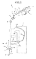
- each spinning unit 2 includes a drafting device 6, an air spinning device 7, a yarn monitoring device 8, a tension sensor 9, a yarn pooling device 11, a waxing device 12, and a winding device 13. These devices are arranged in the running direction of the yarn Y in the stated order from the upstream side. These devices are directly or indirectly supported by a machine frame 62, in such a manner that the devices positioned on the upstream side are positioned higher in the height direction of the machine (i.e., the devices positioned on the downstream side are positioned lower in the height direction of the machine).
- One unit controller 50 is arranged for each predetermined number of the spinning units 2.
- the unit controller 50 controls operations of the spinning units 2.
- the unit controller 50 controls the operations of the spinning units 2 based on information (signal) output from the main controlling device 55.
- the drafting device 6 drafts a sliver (a fiber bundle) S.
- the drafting device 6 includes a back roller pair 14, a third roller pair 15, a middle roller pair 16, and a front roller pair 17. These rollers are arranged in the running direction of the sliver S in the stated order from the upstream side.
- the air spinning device 7 forms the yarn Y by twisting a fiber bundle F drafted by the drafting device 6 by using the swirling air current. More specifically (although not shown), the air spinning device 7 includes a spinning chamber, a fiber guiding member, one or more swirling air current generating nozzles, and a hollow guide shaft body.
- the fiber guiding member guides to the spinning chamber the fiber bundle F supplied thereto from the upstream drafting device 6.
- the swirling air current generating nozzles are arranged around the path on which the fiber bundle F runs. As a result of the force of air injected from the swirling air current generating nozzles, the swirling air current is generated in the spinning chamber.
- the swirling air current causes ends of multiple fibers constituting the fiber bundle F to be reversed and swirled.
- the hollow guide shaft body guides the yarn Y from the inside of the spinning chamber to the outside of the air spinning device 7.
- the yarn monitoring device 8 is arranged between the air spinning device 7 and the yarn pooling device 11.
- the yarn monitoring device 8 is an optical yarn monitoring device that detects the state of the yarn Y by irradiating light on the running yarn Y.
- the yarn monitoring device 8 monitors the state of the running yarn Y and detects whether the yarn Y has any yarn defect.
- the yarn monitoring device 8 transmits a yarn defect detection signal to the unit controller 50.
- the yarn monitoring device 8 detects, for example, an abnormal thickness of the yarn Y and/or foreign material in the yarn Y.
- the yarn monitoring device 8 also detects yarn breakage.
- the tension sensor 9 is arranged between the air spinning device 7 and the yarn pooling device 11 and it measures a tension level of the running yarn Y and transmits a tension measurement signal to the unit controller 50.
- the unit controller 50 determines that there is an abnormality based on the detection result received from the yarn monitoring device 8 and/or the tension sensor 9, the unit controller 50 causes the yarn Y to be disconnected in the specific spinning unit 2. More specifically, the yarn Y is cut by stopping the air supply to the air spinning device 7 thereby discontinuing the formation of the yarn Y. Alternatively, the yarn Y can be cut with a separate cutter.
- the waxing device 12 applies wax to the yarn Y at a position between the yarn pooling device 11 and the winding device 13.
- the yarn pooling device 11 eliminates slack in the yarn Y at a position between the air spinning device 7 and the winding device 13.
- the yarn pooling device 11 has a function of stably pulling the yarn Y from the air spinning device 7, a function of preventing slackening of the yarn Y by pooling the yarn Y fed-out from the air spinning device 7 while, for example, the yarn joining carrier 3 is performing a yarn joining operation, and a function of preventing a fluctuation in the tension level of the yarn Y positioned on the downstream side of the yarn pooling device 11 from being conveyed to the air spinning device 7.
- the winding device 13 forms the package P by winding the yarn Y around a bobbin B.
- the winding device 13 includes a package holding part 21, a winding drum 22, and a traverse guide 23.
- the package holding part 21 rotatably supports the bobbin B.
- the package holding part 21 is swingably supported by a support shaft 24.
- the package holding part 21 can bring the surface of the bobbin B or the surface of the package P into contact with the surface of the winding drum 22 with an appropriate pressure.
- a not-shown driving motor arranged in the second end frame 5B drives all the winding drums 22 of plural spinning units 2 at the same time. As a result, the bobbins B or the packages P are rotated in the winding direction in the spinning units 2.
- the traverse guides 23 of plural spinning units 2 are arranged on a shaft 25 that is shared among the spinning units 2.
- Each traverse guide 23 traverses the yarn Y within a predetermined width with respect to the rotating bobbin B or the package P, as a result of a not-shown driving motor arranged in the second end frame 5B driving the shaft 25 to reciprocate in the rotation axis direction of the winding drum 22.
- the yarn joining carrier 3 When the yarn Y is disconnected or when the yarn Y is broken for some reason in any of the spinning units 2, the yarn joining carrier 3 travels to the specific spinning unit 2 and performs the yarn joining operation.
- the yarn joining carrier 3 includes a suction pipe 31, a yarn joining device 37, a suction mouth 38, and a yarn joining carrier controlling section 3A.
- the suction pipe 31 is swingably supported by a support shaft 31A.
- the suction pipe 31 catches the yarn Y from the air spinning device 7 and guides the yarn Y to the yarn joining device 37.
- the suction mouth 38 is swingably supported by a support shaft 38A.
- the suction mouth 38 catches the yarn Y from the winding device 13 and guides the yarn Y to the yarn joining device 37.
- the yarn joining device 37 joins the yarns Y that were guided thereto.
- the yarn joining device 37 can be a splicer that uses compressed air, a piecer that uses seed yarn, or a knotter that mechanically joins the yarns Y.
- the yarn joining carrier controlling section 3A performs various control operations on the yarn joining carrier 3.
- the yarn joining carrier 3 While performing the yarn joining operation, the yarn joining carrier 3 rotates the package P in a direction that is opposite to the winding direction (reverse rotation). When doing so, the package holding part 21 is moved by a not-shown air cylinder in such a manner that the package P is separated from the winding drum 22, and then the package P is reversely rotated by a reverse rotating roller 36 arranged in the yarn joining carrier 3.
- the back roller pair 14 includes a back bottom roller 14A and a back top roller 14B opposing each other across a running path R1 of the sliver S.
- the third roller pair 15 includes a third bottom roller 15A and a third top roller 15B opposing each other across the running path R1.
- the middle roller pair 16 includes a middle bottom roller 16A and a middle top roller 16B opposing each other across the running path R1.
- An apron belt 18A is stretched over the middle bottom roller 16A of the middle roller pair 16.
- An apron belt 18B is stretched over the middle top roller 16B of the middle roller pair 16.
- the front roller pair 17 includes a front bottom roller 17A and a front top roller 17B opposing each other across the running path R1.
- the drafting roller pairs 14, 15, 16, and 17 send the sliver S supplied from a not-shown can and guided by a fiber bundle guide 65, from the upstream side to the downstream side, while drafting the sliver S.
- the bottom rollers 14A, 15A, 16A, and 17A are supported by rotation shafts 14C, 15C, 16C, and 17C, respectively.
- the rotation shafts 14C, 15C, 16C, and 17C are supported by the machine frame 62 via bearings.
- the front bottom roller 17A is supported by the machine frame 62 via bearings 117 shown in FIG. 9 .
- the bottom rollers 14A, 15A, 16A, and 17A are driven to rotate by the driving motor arranged in the second end frame 5B or a driving motor arranged in each spinning unit 2.
- the bottom rollers 14A and 15A are driven by driving motors arranged in each spinning unit 2
- the bottom rollers 16A and 17A are driven by driving motors 120A and 120B arranged in the second end frame 5B, respectively.
- the top rollers 14B, 15B, 16B, and 17B are rotatably supported by the support shafts 14D, 15D, 16D, and 17D, respectively.
- the support shafts 14D, 15D, 16D, and 17D are supported by a cradle 61 via roller supporting structures 90, 90, and 90 (see FIG. 6 ).
- the top rollers 14B, 15B, 16B, and 17B are attached to the cradle 61 while being positioned so as to oppose the bottom rollers 14A, 15A, 16A, and 17A, respectively.
- the top rollers 14B, 15B, 16B, and 17B are driven rollers that are driven to rotate while being in contact with the bottom rollers 14A, 15A, 16A, and 17A, respectively.
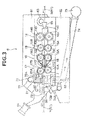
- the cradle 61 is swingable about a support shaft 63 between a position (hereinafter, "contact position") at which the top rollers 14B, 15B, 16B, and 17B are in contact with the bottom rollers 14A, 15A, 16A, and 17A, respectively, with predetermined pressure (see FIG. 3 ) and another position at which the top rollers 14B, 15B, 16B, and 17B are separated from the bottom rollers 14A, 15A, 16A, and 17A, respectively (see FIG. 4 ).
- the swinging of the cradle 61 is realized by operating a handle 64 arranged on the cradle 61.
- a hook part 66 arranged at the lower tip end of the handle 64 is engaged with a fixation roller 67 of the machine frame 62, so that the top rollers 14B, 15B, 16B, and 17B are held in contact with and pressed against the bottom rollers 14A, 15A, 16A, and 17A, respectively.
- the cradle 61 rotatably supports the top rollers 14B, 15B, 16B, and 17B in the drafting devices 6 included in a pair of adjacent spinning units 2.
- the cradle 61 is shared by the drafting devices 6, each of which is included in a different one of the two adjacent spinning units 2.
- the drafting device 6 includes a suction member (a supporting member) 71 and a blowing member 81.
- the suction member 71 sucks in fiber waste scattered by the top rollers 14B, 15B, 16B, and 17B.
- the suction member 71 sucks in fiber waste scattered by the front top roller 17B.
- the suction member 71 includes a first suction transport tube (a tubular part) 72 and a second suction transport tube 74.
- a suction port 72A is arranged on one end of the first suction transport tube 72. Foreign matter such as fiber waste sucked by the suction port 72A are transported through the first suction transport tube 72.
- the first suction transport tube 72 is supported by a fixed part 76 of the cradle 61 via a fixing part (a resonance preventing structure) 77.
- the suction port 72A is positioned downstream of the front top roller 17B and slightly above the contact (nip) position between the front top roller 17B and the front bottom roller 17A.
- the suction port 72A is positioned so as to face the front top roller 17B.
- a first connecting member 72B is arranged on the other end of the first suction transport tube 72.
- the fixing part 77 (see FIG. 5 ) is a plate-like member.
- a main surface 77A of the fixing part 77 is fixed to the cradle 61 (see FIGS. 3 and 4 ) so as to be orthogonal to (so as to intersect) the direction in which the drafting rollers pairs 14, 15, 16, and 17 (which hereinafter may simply be referred to as "drafting rollers") are arranged.
- the first suction transport tube 72 is fixed to the fixed part 76, as a result of fixing members being inserted and being fixed into insertion holes 77C formed in the fixing part 77 and insertion holes (not shown) formed in the cradle 61.
- the main surface 77A of the fixing part 77 has formed thereon a third reinforcing part (a resonance preventing structure) 77B that protrudes in the thickness direction of the fixing part 77 toward the downstream side with respect to the conveying direction of the sliver S.
- the third reinforcing part 77B is formed by applying extruding processing to the fixing part 77, which is the plate-like member, from one of the surfaces thereof.
- the thickness of the third reinforcing part 77B can be equal to or different from the thickness of other parts that do not protrude in the thickness direction.
- a not-shown second reinforcing part can be arranged on the first suction transport tube 72. More specifically, the second reinforcing part can be formed by processing the external surface of the first suction transport tube 72 and it is a part that is arranged along the axial direction of the first suction transport tube 72.
- the second reinforcing part is a reinforcing part that can be arranged to protrude from the inside toward the outside of the first suction transport tube 72 or can be thickened in the thickness direction of the first suction transport tube 72.
- the second suction transport tube 74 is connectable to the first suction transport tube 72.
- the fiber waste sucked by the suction port 72A is transported through the second suction transport tube 74 via the first suction transport tube 72.
- the second suction transport tube 74 is fixed to the machine frame 62.
- a second connecting member 74A is arranged on one end of the second suction transport tube 74.
- the second connecting member 74A is a part that enables the second suction transport tube 74 to be connected to and disconnected from the first connecting member 72B of the first suction transport tube 72.
- the second connecting member 74A makes contact with the first connecting member 74B.
- the first connecting member 72B makes contact with the second connecting member 74A, the first suction transport tube 72 and the second suction transport tube 74 are connected to each other.
- the other end of the second suction transport tube 74 is connected to a main tube 75.
- the main tube 75 is positioned on the rear side of the spinning units 2 and serves as a suction transport tube shared among plural the spinning units 2.
- the main tube 75 is connected to a blower (a suction source) arranged in the first end frame 5A.
- the blowing member 81 removes fiber waste accumulated in the air spinning device 7 by blowing compressed air.
- the hollow guide shaft body of the air spinning device 7 moves away (opens) from the fiber guiding member.
- the blowing member 81 removes fiber waste by blowing the compressed air onto the air spinning device 7 (more specifically, the entrance of the fiber guiding member).
- the blowing member 81 includes a blowing outlet 82A, a first blowing tube 82, and a second blowing tube 83.
- the blowing outlet 82A is arranged on one end of the first blowing tube 82.
- the blowing member 81 sends the compressed air to the blowing outlet 82A via the first blowing tube 82 and blows the compressed air onto the air spinning device 7.
- the first blowing tube 82 is positioned with respect to the corresponding one of the first suction transport tubes 72.
- the other end of the first blowing tube 82 is connected to the first connecting member 72B.
- the second blowing tube 83 is connectable to the first blowing tube 82.
- the compressed air is sent to the first blowing tube 82 and the blowing outlet 82A via the second blowing tube 83.
- the second blowing tube 83 is fixed to the machine frame 62.
- One end of the second blowing tube 83 is connected to the second connecting member 74A.
- the other end of the second blowing tube 83 is connected to a not-shown air source via a not-shown valve.
- the cradle 61 of the drafting devices 6 includes the roller supporting structures 90, 90, and 90, as well as a cover part 91.
- the cover part 91 is formed in the shape of a bottomless hollow box by using a metal plate (a plate-like member).
- the cover part 91 includes attachment parts 92 and 92.
- the attachment parts 92 and 92 are parts formed by perpendicularly bending lower parts of the lateral faces of the cover part 91 outwardly and are used to fix the cover part 91 and the roller supporting structures 90, 90, and 90 to each other.
- the cover part 91 and the roller supporting structures 90, 90, and 90 are fixed to each other as a result of inserting and fixing insertion fixing parts 92B into insertion holes 90A, 90A, and 90A formed in the roller supporting structures 90 and into insertion holes 92A formed in the attachment parts 92 and 92.
- a triangular rib (a resonance preventing structure) 95 and plural first reinforcing parts (resonance preventing structures) 96 are formed on at least one lateral face 94 of the cover part 91.
- the lateral face 94 is a face orthogonal to (intersecting) the axial directions of the top rollers 14B, 15B, 16B, and 17B.
- the lateral face 94 is formed by applying bending processing to the plate-like member. In other words, the lateral face 94 is formed by applying the bending processing to a position between the attachment part 92 and the lateral face 94 and to a position between the lateral face 94 and a top face 93.
- the triangular rib 95 is a rib formed in the section to which the bending processing was applied and which is positioned between the attachment part 92 and the lateral face 94. As shown in FIG. 7B , the triangular rib 95 diagonally connects the attachment part 92 and the lateral face 94 to each other. The triangular rib 95 is formed at a position that overlaps with the position of the support shaft 17D supporting the front top roller 17B (see FIG. 6 ) in a planar view of the cover part 91 from above.
- each first reinforcing part 96 is formed on the lateral face 94 so as to protrude in the thickness direction of the plate-like member forming the lateral face 94, i.e., in the direction from the inside toward the outside of the cover part 91.
- Plural first reinforcing parts 96 extend in the direction orthogonal to (intersecting) the axial directions of the top rollers 14B, 15B, 16B, and 17B and to the direction in which the drafting rollers are arranged.
- Each first reinforcing part 96 is arranged along the direction in which the drafting rollers are arranged.
- the first reinforcing parts 96 are reinforcing parts formed by applying extruding processing to the lateral face 94, which is the plate-like member, from the rear surface thereof.
- the thickness of each of the first reinforcing parts 96 can be equal to or different from the thickness of other parts that do not protrude in the thickness direction.
- One of the first reinforcing parts 96 is formed at a position that overlaps the position of the support shaft 17D supporting the front top roller 17B in a planar view of the cover part 91 from above.
- the first reinforcing parts 96 can be formed by increasing the thickness of the plate-like member in a part thereof.
- Plural pressing mechanisms 100 are arranged on the inside of the cover part 91 for the purpose of nipping the sliver S between the top rollers 14B, 15B, 16B, and 17B and the bottom rollers 14A, 15A, 16A, and 17A. Explanation will be given below by taking the pressing mechanism 100 of the front top rollers 17B as an example.
- the pressing mechanism 100 includes a spring holding frame 101, a pressing spring 102, a pressing force adjusting cam 103, and a pressing member 104.
- the spring holding frame 101 is a metal-plate member formed around the pressing spring 102 and is attached to the roller supporting structure 90.
- the spring holding frame 101 is a hollow member whereby the pressing spring 102, the pressing force adjusting cam 103, and the pressing member 104 can be housed in the space thereof.
- the pressing spring 102 is a coil spring and is installed in the spring holding frame 101 in a compressed state.
- the pressing force adjusting cam 103 is attached to one end of the pressing spring 102, whereas the pressing member 104 is attached to the other end of the pressing spring 102.
- the pressing force adjusting cam 103 includes an operating tool 105.
- the pressing force adjusting cam 103 can be expanded and compressed in the axial directions by rotating the operating tool 105.
- the operating tool 105 protrudes to the outside through a through hole 101A formed through the spring holding frame 101.
- the pressing member 104 includes a receiving plate 107 that is disc-shaped and that receives the end of the pressing spring 102, as well as a pressing pin 110 that is in the shape of a round rod.
- a through hole 90B is formed through the roller supporting structure 90 into which the pressing pin 110 can be inserted.
- the pressing pin 110 is inserted into the through hole 90B from above so as to project into the inside of the roller supporting structure 90.
- the through hole 90B supports the pressing pin 110 in such a manner that the pressing pin 110 is slidable in the longitudinal direction.
- the end (the lower end) of the pressing pin 110 inserted in the through hole 90B is in contact with a center part, in terms of the axial direction, of the support shaft (a first rod member, a second rod member) 17D for the front top rollers 17B so as to press the support shaft 17D downward with an elastic force of the pressing spring 102.
- a center part, in terms of the axial direction, of the support shaft (a first rod member, a second rod member) 17D for the front top rollers 17B so as to press the support shaft 17D downward with an elastic force of the pressing spring 102.
- a wave washer (a damper) 109 is arranged in a penetrated state on the outside of the operating tool 105 of the pressing force adjusting cam 103. As shown in FIG. 6 , under a state in which the pressing mechanism 100 is housed in the cover part 91, the wave washer 109 is held as being sandwiched between the top face 101B of the spring holding frame 101 and the top face 93 of the cover part 91. In place of the wave washer 109, an air damper or a hydraulic damper may be arranged.
- each of the pressing mechanisms 100 of the back top rollers 14B, the third top rollers 15B, and the middle top rollers 16B is the same as the configuration of the pressing mechanism 100 of the front top rollers 17B. Therefore, detailed explanations thereof will be omitted.
- the support shafts 14D, 15D, 16D, and 17D supporting the top rollers 14B, 15B, 16B, and 17B, respectively, are urged by the pressing springs 102 so as to press the bottom rollers 14A, 15A, 16A, and 17A.
- the sliver S can be nipped between the top rollers 14B, 15B, 16B, and 17B and the bottom rollers 14A, 15A, 16A, and 17A.
- the diameter ⁇ of the support shaft 17D supporting the front top rollers 17B may be arranged, preferably, to fall in the range from 8.5% to 11.5% inclusive of a distance P1 between the front top rollers 17B provided on the two ends of the support shaft 17D and may be arranged, more preferably, to fall in the range from 9.0% to 10.0% inclusive of the distance P1.
- the distance P1 between the front top rollers 17B and 17B arranged on the two ends of the support shaft 17D denotes the distance between the centers of the front top rollers 17B and 17B along the length of the support shaft 17D in the axial direction.
- the diameter of each of the support shafts 14D to 16D can be equal to that of the support shaft 17D.
- the rotation shaft 17C (a third rod member) supporting the front bottom rollers 17A is supported with respect to the machine frame 62 via the bearings 117.
- the rotation shaft 17C is connected to the driving motor 120B arranged in the second end frame 5B and is driven by the driving motor 120B.
- the bearings 117 are fixed to fixed parts 118 that are fixed to the machine frame 62.
- the rotation shaft 17C is rotatably supported with respect to the fixed parts 118, i.e., the machine frame 62.
- the two bearings 117 e.g., a bearing (a first bearing) 117A and another bearing (a second bearing) 117B) are positioned adjacent to each other in the axial direction of the rotation shaft 17C.
- the number of the balls in the bearing 117A is different from the number of the balls in the bearing 117B.
- the main controlling device 55 includes a Central Processing Unit (CPU), a Read-Only Memory (ROM), a Random Access Memory (RAM), and the like. As shown in FIG. 10 , the main controlling device 55 includes a prohibiting section (a controlling section) 55A and a storage section 55B, as conceptual parts that execute a controlling process with respect to the drafting rollers of the drafting devices 6.
- CPU Central Processing Unit
- ROM Read-Only Memory
- RAM Random Access Memory
- the main controlling device 55 receives a setting of a rotational speed of the drafting rollers from an operator via the input keys K.
- the storage section 55B stores therein the rotational speed of the drafting rollers per unit time, when the drafting rollers resonate with other members (e.g., the cradle 61, the rotation shafts 14C, 15C, 16C, and 17C, the suction member 71, the bearings 117, and the like.).
- the rotational speeds in the range of 433 ⁇ m/min can be stored in the storage section 55B.
- the prohibiting section 55A checks whether the input value corresponds with a value stored in the storage section 55B. When having confirmed that the input value corresponds with the value stored in the storage section 55B, the prohibiting section 55A controls the display section D so as to display that it is not possible to set the input rotational speed. On the contrary, when having confirmed that the input value does not correspond with the value stored in the storage section 55B, the prohibiting section 55A controls the driving motors (e.g., the driving motors 120A and 120B) so as to drive the drafting rollers at the rotational speed corresponding to the input value.
- the driving motors e.g., the driving motors 120A and 120B
- the drafting device 6 By using the drafting device 6 according to the present embodiment, it is possible to prevent the occurrence of resonance between the supporting members, which directly or indirectly support the drafting rollers, and the drafting rollers that may be caused by the rotation of the drafting rollers. As a result, it is possible to prevent degradation of the physical properties of the yarn.
- the lateral face 94 of the cradle 61 is reinforced by the triangular rib 95 as shown in FIG. 7A , it is possible to reduce vibration of the cradle 61 caused by the rotation of the top rollers 14B, 15B, 16B, and 17B. As a result, it is possible to prevent the occurrence of resonance between the cradle 61, which serves as a supporting member, and the drafting rollers that may be caused by the rotation of the drafting rollers.
- the first reinforcing parts 96 are formed on the lateral face 94 of the cradle 61, as shown in FIG. 7A .
- Each first reinforcing part 96 extends in the direction that intersects the direction in which vibration is applied by the top rollers 14B, 15B, 16B, and 17B.
- the first reinforcing parts 96 are arranged side by side along the direction in which the vibration is applied by the top rollers 14B, 15B, 16B, and 17B.
- the diameter ⁇ of the support shaft 17D is, as shown in FIG. 8 , arranged to fall in the range from 8.5% to 11.5% inclusive of the distance P1 between the front top rollers 17B and 17B arranged on the two ends of the support shaft 17D.
- the fixing part 77 is reinforced by the third reinforcing part 77B as shown in FIG. 5 , it is possible to reduce vibration of the fixing part 77 that may be caused by the rotation of the top rollers 14B, 15B, 16B, and 17B. As a result, it is possible to prevent the occurrence of resonance between the suction member 71, which serves as a supporting member, and the drafting rollers that may be caused by the rotation of the drafting rollers.
- the third reinforcing part 77B protruding in the direction in which the vibration is applied by the top rollers 14B, 15B, 16B, and 17B is formed on the main surface 77A of the fixing part 77.
- the bearing 117A and the bearing 117B are positioned adjacent to each other as shown in FIG. 9 .
- the bearing 117A includes the balls of which the number is adjusted to be different from the number of the balls in the bearing 117B. As a result, it is possible to prevent the occurrence of resonance between the bearings 117, which serve as supporting members, and the drafting rollers that may be caused by the rotation of the drafting rollers.
- the drafting rollers it is prohibited to set the drafting rollers to be driven at such a rotational speed at which the drafting rollers may resonate with at least one of the supporting members such as the cradle 61, the support shafts 14D, 15D, 16D, and 17D, the suction member 71, the bearings 117, and the like.
- the supporting members such as the cradle 61, the support shafts 14D, 15D, 16D, and 17D, the suction member 71, the bearings 117, and the like.
- each of the drafting devices 6 includes the cradle 61, the support shafts 14D, 15D, 16D, and 17D, the suction member 71, and the bearings 117, as the supporting members.
- the resonance preventing structures are: the triangular rib 95 and the first reinforcing parts 96 arranged on the lateral face 94 of the cover part 91 of the cradle 61, the support shafts 14D, 15D, 16D, and 17D of which the diameters are adjusted, the pressing mechanism 100 provided with the wave washer 109, the suction member 71 having the fixing part 77 that has the third reinforcing part 77B formed thereon, and the bearings 117A and 117B that are positioned adjacent to each other and include the balls in the mutually-different numbers.
- the drafting device of the present invention does not necessarily have to include all of these components.
- the drafting device may include any of these components that are used in combination as appropriate.
- the example is explained in which the main controlling device 55 carries out control so that such a rotational speed at which resonance may occur between the drafting rollers and at least one of the supporting members cannot be set as the rotational speed of the drafting rollers (the drafting roller pairs 14, 15, 16, and 17).
- the spinning units do not necessarily have to have this function.
- the example is explained in which the cover part 91 of the cradle 61 is formed by the metal plate; however, the cover part 91 can be formed with cast metal.
- the cover part 91 is formed with cast metal, the cradle 61 becomes more stable because the weight of the cover part 91 increases.
- roller pairs are arranged as the drafting rollers.
- more or less roller pairs such as three pairs or five pairs may be arranged.
- the main controlling device 55 carries out the driving control with respect to the drafting rollers (the pairs of drafting rollers 14, 15, 16, and 17).
- the unit controller 50 or a controller arranged for each of the spinning units 2 may carry out such a driving control.
- the air spinning device can further include a needle that is held by the fiber guiding member so as to protrude into the spinning chamber to prevent the twist of the fiber bundle from being transmitted to the upstream side of the air spinning device.
- the air spinning device can be configured so that a downstream end part of the fiber guiding member prevents the twist of the fiber bundle from being transmitted to the upstream side of the air spinning device.
- the air spinning device may include a pair of air jet nozzles each of which apply a twist in opposite directions.
- the yarn pooling device 11 has the function of pulling the yarn Y from the air spinning device 7.
- the yarn may be pulled from the air spinning device 7 by using a delivery roller and a nip roller.
- a slack tube that absorbs slack of the yarn Y by using a suction air current or a mechanical compensator may be arranged in place of the yarn pooling device 11.
- the spinning machine 1 is configured so that at least one of the bottom rollers in the drafting device 6 and the traverse guide 23 are driven by the power supplied from the second end frame 5B (i.e., the driving power is shared among plural spinning units 2).
- the various components e.g., the drafting device, the spinning device, the winding device, and the like
- each of the spinning units 2 may be driven independently of the various components included in the other spinning units 2.
- the tension sensor 9 can be arranged upstream of the yarn monitoring device 8 in terms of the running direction of the yarn Y.
- the unit controller 50 can be arranged for each spinning unit 2.
- the spinning units 2 each do not necessarily have to include the waxing device 12, the tension sensor 9, and the yarn monitoring device 8.
- FIG. 1 illustrates the example in which the spinning machine 1 winds yarn Y into a cheese-shaped package P
- the spinning machine 1 is also able to wind the yarn Y into a cone-shaped package.
- the yarn may slacken due to the traversing of the yarn.
- the yarn pooling device 11 is able to absorb the slack.
- the example is explained in which the drafting device 6 is provided in the spinning machine 1.
- the drafting device 6 can be provided in any of other types of textile machines such as a ring spinning frame or a drawing frame.
- the drafting device configured in this manner is able to prevent the occurrence of resonance between the supporting member, which directly or indirectly supports the drafting rollers, and the drafting rollers that may be caused by the rotation of the drafting rollers. As a result, it is possible to prevent degradation of the physical properties of the yarn.
- the supporting member can include a cradle that rotatably supports the top rollers.
- the drafting device configured in this manner is able to prevent the occurrence of resonance between the cradle, which serves as the supporting member, and the drafting rollers that may be caused by the rotation of the drafting rollers.
- the cradle can have a lateral face that is formed by applying bending processing to a plate-like member.
- the resonance preventing structure can be at least one of a rib that is formed in a region including a section to which the bending processing is applied, and first reinforcing parts each of which is formed by processing the lateral face and each of which extends in a direction intersecting axial directions of the top rollers and a direction in which the roller pairs are arranged, the first reinforcing parts being arranged side by side along the direction in which the roller pairs are arranged.
- the lateral face of the cradle is reinforced by the rib or vibration of the cradle in the direction in which vibration is applied by the top rollers is inhibited by the first reinforcing parts formed on the lateral face of the cradle.
- the supporting member can include a first rod member that is supported by the cradle and that rotatably supports on two ends thereof, one of the top rollers and a top roller of an adjacent drafting device arranged adjacent to the drafting device in an axial direction of the top rollers, and the resonance preventing structure can be realized by a dimension of a diameter of the first rod member formed so as to fall in a range from 8.5% to 11.5% inclusive of a distance between the adjacent top rollers.
- an elastic member that presses in a direction in which the bottom rollers are arranged a second rod member that rotatably supports the top rollers on two ends thereof can be arranged in the cradle, and the resonance preventing structure can be a damper arranged between the cradle and the elastic member.
- the damper arranged between the cradle and the elastic member prevents vibration transmitted from the second rod member from being further transmitted to the cradle.
- the damper arranged between the cradle and the elastic member prevents vibration transmitted from the second rod member from being further transmitted to the cradle.
- the supporting member can include a suction member that includes a tubular part having a suction port arranged facing at least one of the drafting rollers; and a fixing part configured with a plate-like member for fixing the tubular part to the cradle that rotatably supports the top rollers.
- the resonance preventing structure can be at least one of a second reinforcing part formed by processing an external surface of the tubular part, and a third reinforcing part formed by processing the fixing part.
- the drafting device configured in this manner, because at least one of the tubular part and the fixing part is reinforced by one or both of the second reinforcing part and the third reinforcing part, it is possible to reduce vibration of the tubular part and the fixing part that may be caused by the rotation of the top rollers. As a result, it is possible to prevent the occurrence of resonance between the suction member, which serves as the supporting member, and the drafting rollers that may be caused by the rotation of the drafting rollers.
- a main surface of the fixing part can be fixed to the cradle so as to intersect the direction in which the drafting roller is arranged.
- the supporting member can include a first bearing and a second bearing each of which rotatably supports a third rod member that supports the bottom rollers of one of the drafting rollers with respect to a machine frame.
- the first bearing and the second bearing can be positioned adjacent to each other, and the resonance preventing structure can be realized by adjusting number of balls in the second bearing to be different from number of balls in the first bearing.
- the drafting device configured in this manner is able to prevent the occurrence of resonance between the bearings, which serve as the supporting member, that may be caused by the rotation of the drafting rollers.
- a spinning unit includes the above drafting device; a spinning device that forms yarn by twisting the fiber bundle drafted by the drafting device; a winding device that winds the yarn supplied thereto from the spinning device into a package; and a controlling section that prohibits the drafting rollers from being driven at such a speed that causes the drafting rollers to resonate with the supporting member in the drafting device.
- the drafting rollers are prohibited from being driven at such a rotational speed that causes the drafting rollers to resonate with other supporting member such as the cradle, the first rod member, the second rod member, the suction member, the bearings, and the like.
- other supporting member such as the cradle, the first rod member, the second rod member, the suction member, the bearings, and the like.
- the term “yarn” denotes not only yarn, but also fibers in a bundle form such as a sliver.
Landscapes
- Engineering & Computer Science (AREA)
- Mechanical Engineering (AREA)
- Textile Engineering (AREA)
- Spinning Or Twisting Of Yarns (AREA)
Abstract
Description
- The present invention relates to a drafting device and a spinning unit.
- In a spinning unit and a spinning machine that are known, spun yarn is produced by causing a drafting device to draft a fiber bundle and causing an air spinning device to twist the drafted fiber bundle.
Japanese Patent Application Laid-open No. 2011-32618 - However, the conventional drafting device has room for improvement from the viewpoint of preventing the physical properties of the yarn from being degraded.
- It is an object of the present invention to provide a drafting device and a spinning unit capable of preventing degradation of the physical properties of yarn.
- According to an aspect of the present invention, a drafting device that drafts a fiber bundle includes plural drafting rollers arranged successively in a direction in which the fiber bundle is conveyed, the drafting rollers being arranged as plural roller pairs, each roller pair having a top roller and a bottom roller opposing the top roller; a supporting member that supports the drafting rollers; and a resonance preventing structure that prevents occurrence of resonance between the drafting rollers and the supporting member that may be caused by rotation of the drafting rollers.
- According to another aspect of the present invention, a spinning unit includes the above drafting device; a spinning device that forms yarn by twisting the fiber bundle drafted by the drafting device; a winding device that winds the yarn supplied thereto from the spinning device into a package; and a controlling section that prohibits the drafting rollers from being driven at such a speed that causes the drafting rollers to resonate with the supporting member in the drafting device.
-
-
FIG. 1 is a front view of a spinning machine according to an embodiment. -
FIG. 2 is a side view of a spinning unit of the spinning machine shown inFIG. 1 . -
FIG. 3 is a side view of a drafting device shown inFIG. 2 . -
FIG. 4 is another side view of the drafting device shown inFIG. 2 ; -
FIG. 5 is a front view of a suction member shown inFIGS. 3 and4 . -
FIG. 6 is an exploded perspective view of a cradle in the drafting device. -
FIG. 7A is a partial enlarged view of a cover part shown inFIG. 6 . -
FIG. 7B is a cross-sectional view at the line VIIB-VIIB inFIG. 7A . -
FIG. 8 is a perspective view of front top rollers shown inFIG. 6 . -
FIG. 9 is a plan view of bottom rollers in the drafting device shown inFIG. 2 . -
FIG. 10 is a functional block diagram showing functions of the spinning machine. - Exemplary embodiments of the present invention are explained in detail below with reference to the accompanying drawings. The same or corresponding elements in the drawings will be referred to by using the same reference characters, and duplicate explanations thereof will be omitted. The dimensional proportions in the drawings are not necessarily the same as those in the explanation.
- As shown in
FIG. 1 , a spinning machine 1 includes plural spinning units 2, a yarn joining carrier 3, a first end frame 5A, and asecond end frame 5B. The plural spinning units 2 are arranged in a line. In the below explanation, on a path on which a yarn Y runs (i.e., a yarn path), the side on which the yarn Y is formed will be referred to as the upstream side, whereas the side on which the yarn Y is wound will be referred to as the downstream side. - Each spinning unit 2 forms a yarn Y and winds the formed yarn Y into a package P. When the yarn Y is disconnected in any of the spinning units 2 or when the yarn Y is broken for some reason, the yarn joining carrier 3 performs a yarn joining operation in that spinning unit 2.
- The first end frame 5A houses therein an air source that generates a swirling air current in various components of the spinning units 2 and/or a suction source that generates a suction air current in various components of the spinning units 2, and the like.
- The
second end frame 5B houses therein a driving motor and the like to supply power to various components of the spinning units 2. Thesecond end frame 5B includes a main controllingdevice 55, a display section D, and one or more input keys K. - The main controlling
device 55 controls and manages each component of the spinning machine 1 in a centralized manner. The display section D displays specifics of settings and/or information related to the state of the spinning units 2. An operator can perform various settings in the spinning units 2 by appropriately operating the input keys K. - As shown in
FIGS. 1 and2 , each spinning unit 2 includes a drafting device 6, anair spinning device 7, a yarn monitoring device 8, atension sensor 9, ayarn pooling device 11, awaxing device 12, and awinding device 13. These devices are arranged in the running direction of the yarn Y in the stated order from the upstream side. These devices are directly or indirectly supported by amachine frame 62, in such a manner that the devices positioned on the upstream side are positioned higher in the height direction of the machine (i.e., the devices positioned on the downstream side are positioned lower in the height direction of the machine). - One
unit controller 50 is arranged for each predetermined number of the spinning units 2. Theunit controller 50 controls operations of the spinning units 2. Theunit controller 50 controls the operations of the spinning units 2 based on information (signal) output from the main controllingdevice 55. - The drafting device 6 drafts a sliver (a fiber bundle) S. The drafting device 6 includes a
back roller pair 14, athird roller pair 15, amiddle roller pair 16, and afront roller pair 17. These rollers are arranged in the running direction of the sliver S in the stated order from the upstream side. - The
air spinning device 7 forms the yarn Y by twisting a fiber bundle F drafted by the drafting device 6 by using the swirling air current. More specifically (although not shown), theair spinning device 7 includes a spinning chamber, a fiber guiding member, one or more swirling air current generating nozzles, and a hollow guide shaft body. The fiber guiding member guides to the spinning chamber the fiber bundle F supplied thereto from the upstream drafting device 6. The swirling air current generating nozzles are arranged around the path on which the fiber bundle F runs. As a result of the force of air injected from the swirling air current generating nozzles, the swirling air current is generated in the spinning chamber. The swirling air current causes ends of multiple fibers constituting the fiber bundle F to be reversed and swirled. The hollow guide shaft body guides the yarn Y from the inside of the spinning chamber to the outside of theair spinning device 7. - The yarn monitoring device 8 is arranged between the
air spinning device 7 and theyarn pooling device 11. The yarn monitoring device 8 is an optical yarn monitoring device that detects the state of the yarn Y by irradiating light on the running yarn Y. The yarn monitoring device 8 monitors the state of the running yarn Y and detects whether the yarn Y has any yarn defect. When the yarn monitoring device 8 detects a yarn defect, the yarn monitoring device 8 transmits a yarn defect detection signal to theunit controller 50. As the yarn defect, the yarn monitoring device 8 detects, for example, an abnormal thickness of the yarn Y and/or foreign material in the yarn Y. The yarn monitoring device 8 also detects yarn breakage. - The
tension sensor 9 is arranged between theair spinning device 7 and theyarn pooling device 11 and it measures a tension level of the running yarn Y and transmits a tension measurement signal to theunit controller 50. When theunit controller 50 determines that there is an abnormality based on the detection result received from the yarn monitoring device 8 and/or thetension sensor 9, theunit controller 50 causes the yarn Y to be disconnected in the specific spinning unit 2. More specifically, the yarn Y is cut by stopping the air supply to theair spinning device 7 thereby discontinuing the formation of the yarn Y. Alternatively, the yarn Y can be cut with a separate cutter. - The waxing
device 12 applies wax to the yarn Y at a position between theyarn pooling device 11 and the windingdevice 13. - The
yarn pooling device 11 eliminates slack in the yarn Y at a position between theair spinning device 7 and the windingdevice 13. Theyarn pooling device 11 has a function of stably pulling the yarn Y from theair spinning device 7, a function of preventing slackening of the yarn Y by pooling the yarn Y fed-out from theair spinning device 7 while, for example, the yarn joining carrier 3 is performing a yarn joining operation, and a function of preventing a fluctuation in the tension level of the yarn Y positioned on the downstream side of theyarn pooling device 11 from being conveyed to theair spinning device 7. - The winding
device 13 forms the package P by winding the yarn Y around a bobbin B. The windingdevice 13 includes apackage holding part 21, a windingdrum 22, and atraverse guide 23. - The
package holding part 21 rotatably supports the bobbin B. Thepackage holding part 21 is swingably supported by asupport shaft 24. Thepackage holding part 21 can bring the surface of the bobbin B or the surface of the package P into contact with the surface of the windingdrum 22 with an appropriate pressure. A not-shown driving motor arranged in thesecond end frame 5B drives all the windingdrums 22 of plural spinning units 2 at the same time. As a result, the bobbins B or the packages P are rotated in the winding direction in the spinning units 2. The traverse guides 23 of plural spinning units 2 are arranged on a shaft 25 that is shared among the spinning units 2. Eachtraverse guide 23 traverses the yarn Y within a predetermined width with respect to the rotating bobbin B or the package P, as a result of a not-shown driving motor arranged in thesecond end frame 5B driving the shaft 25 to reciprocate in the rotation axis direction of the windingdrum 22. - When the yarn Y is disconnected or when the yarn Y is broken for some reason in any of the spinning units 2, the yarn joining carrier 3 travels to the specific spinning unit 2 and performs the yarn joining operation. The yarn joining carrier 3 includes a
suction pipe 31, ayarn joining device 37, asuction mouth 38, and a yarn joining carrier controlling section 3A. - The
suction pipe 31 is swingably supported by asupport shaft 31A. Thesuction pipe 31 catches the yarn Y from theair spinning device 7 and guides the yarn Y to theyarn joining device 37. Thesuction mouth 38 is swingably supported by asupport shaft 38A. Thesuction mouth 38 catches the yarn Y from the windingdevice 13 and guides the yarn Y to theyarn joining device 37. Theyarn joining device 37 joins the yarns Y that were guided thereto. Theyarn joining device 37 can be a splicer that uses compressed air, a piecer that uses seed yarn, or a knotter that mechanically joins the yarns Y. The yarn joining carrier controlling section 3A performs various control operations on the yarn joining carrier 3. - While performing the yarn joining operation, the yarn joining carrier 3 rotates the package P in a direction that is opposite to the winding direction (reverse rotation). When doing so, the
package holding part 21 is moved by a not-shown air cylinder in such a manner that the package P is separated from the windingdrum 22, and then the package P is reversely rotated by a reverse rotating roller 36 arranged in the yarn joining carrier 3. - The drafting device 6 will be explained in detail below. As shown in
FIGS. 3 and4 , theback roller pair 14 includes a backbottom roller 14A and a backtop roller 14B opposing each other across a running path R1 of the sliver S. Thethird roller pair 15 includes a thirdbottom roller 15A and a thirdtop roller 15B opposing each other across the running path R1. Themiddle roller pair 16 includes amiddle bottom roller 16A and a middletop roller 16B opposing each other across the running path R1. Anapron belt 18A is stretched over themiddle bottom roller 16A of themiddle roller pair 16. Anapron belt 18B is stretched over the middletop roller 16B of themiddle roller pair 16. Thefront roller pair 17 includes afront bottom roller 17A and a fronttop roller 17B opposing each other across the running path R1. The drafting roller pairs 14, 15, 16, and 17 send the sliver S supplied from a not-shown can and guided by afiber bundle guide 65, from the upstream side to the downstream side, while drafting the sliver S. - The
bottom rollers rotation shafts rotation shafts machine frame 62 via bearings. For example, thefront bottom roller 17A is supported by themachine frame 62 viabearings 117 shown inFIG. 9 . Together with therotation shafts bottom rollers second end frame 5B or a driving motor arranged in each spinning unit 2. As shown inFIG. 9 , in the present embodiment, thebottom rollers bottom rollers motors second end frame 5B, respectively. - As shown in
FIGS. 3 and4 , thetop rollers support shafts support shafts cradle 61 viaroller supporting structures FIG. 6 ). Thetop rollers cradle 61 while being positioned so as to oppose thebottom rollers top rollers bottom rollers - The
cradle 61 is swingable about asupport shaft 63 between a position (hereinafter, "contact position") at which thetop rollers bottom rollers FIG. 3 ) and another position at which thetop rollers bottom rollers FIG. 4 ). - The swinging of the
cradle 61 is realized by operating ahandle 64 arranged on thecradle 61. When thecradle 61 is closed, i.e., when thecradle 61 is in the contact position, ahook part 66 arranged at the lower tip end of thehandle 64 is engaged with afixation roller 67 of themachine frame 62, so that thetop rollers bottom rollers - The
cradle 61 rotatably supports thetop rollers cradle 61 is shared by the drafting devices 6, each of which is included in a different one of the two adjacent spinning units 2. - The drafting device 6 according to the present embodiment includes a suction member (a supporting member) 71 and a blowing
member 81. Thesuction member 71 sucks in fiber waste scattered by thetop rollers suction member 71 sucks in fiber waste scattered by the fronttop roller 17B. As shown inFIGS. 3 to 5 , thesuction member 71 includes a first suction transport tube (a tubular part) 72 and a secondsuction transport tube 74. - A
suction port 72A is arranged on one end of the firstsuction transport tube 72. Foreign matter such as fiber waste sucked by thesuction port 72A are transported through the firstsuction transport tube 72. The firstsuction transport tube 72 is supported by afixed part 76 of thecradle 61 via a fixing part (a resonance preventing structure) 77. Thesuction port 72A is positioned downstream of the fronttop roller 17B and slightly above the contact (nip) position between the fronttop roller 17B and thefront bottom roller 17A. Thesuction port 72A is positioned so as to face the fronttop roller 17B. A first connectingmember 72B is arranged on the other end of the firstsuction transport tube 72. - The fixing part 77 (see
FIG. 5 ) is a plate-like member. Amain surface 77A of the fixingpart 77 is fixed to the cradle 61 (seeFIGS. 3 and4 ) so as to be orthogonal to (so as to intersect) the direction in which the drafting rollers pairs 14, 15, 16, and 17 (which hereinafter may simply be referred to as "drafting rollers") are arranged. More specifically, the firstsuction transport tube 72 is fixed to the fixedpart 76, as a result of fixing members being inserted and being fixed intoinsertion holes 77C formed in the fixingpart 77 and insertion holes (not shown) formed in thecradle 61. Themain surface 77A of the fixingpart 77 has formed thereon a third reinforcing part (a resonance preventing structure) 77B that protrudes in the thickness direction of the fixingpart 77 toward the downstream side with respect to the conveying direction of the sliver S. The third reinforcingpart 77B is formed by applying extruding processing to the fixingpart 77, which is the plate-like member, from one of the surfaces thereof. The thickness of the third reinforcingpart 77B can be equal to or different from the thickness of other parts that do not protrude in the thickness direction. - A not-shown second reinforcing part can be arranged on the first
suction transport tube 72. More specifically, the second reinforcing part can be formed by processing the external surface of the firstsuction transport tube 72 and it is a part that is arranged along the axial direction of the firstsuction transport tube 72. The second reinforcing part is a reinforcing part that can be arranged to protrude from the inside toward the outside of the firstsuction transport tube 72 or can be thickened in the thickness direction of the firstsuction transport tube 72. - The second
suction transport tube 74 is connectable to the firstsuction transport tube 72. The fiber waste sucked by thesuction port 72A is transported through the secondsuction transport tube 74 via the firstsuction transport tube 72. The secondsuction transport tube 74 is fixed to themachine frame 62. - A second connecting
member 74A is arranged on one end of the secondsuction transport tube 74. The second connectingmember 74A is a part that enables the secondsuction transport tube 74 to be connected to and disconnected from the first connectingmember 72B of the firstsuction transport tube 72. When thecradle 61 is closed so as to be in the contact position, the second connectingmember 74A makes contact with the first connecting member 74B. When the first connectingmember 72B makes contact with the second connectingmember 74A, the firstsuction transport tube 72 and the secondsuction transport tube 74 are connected to each other. - The other end of the second
suction transport tube 74 is connected to amain tube 75. Themain tube 75 is positioned on the rear side of the spinning units 2 and serves as a suction transport tube shared among plural the spinning units 2. Themain tube 75 is connected to a blower (a suction source) arranged in the first end frame 5A. - The blowing
member 81 removes fiber waste accumulated in theair spinning device 7 by blowing compressed air. In the present embodiment, when a yarn disconnection and/or a yarn breakage occur in any of the spinning units 2, the hollow guide shaft body of theair spinning device 7 moves away (opens) from the fiber guiding member. In that situation, the blowingmember 81 removes fiber waste by blowing the compressed air onto the air spinning device 7 (more specifically, the entrance of the fiber guiding member). The blowingmember 81 includes ablowing outlet 82A, afirst blowing tube 82, and asecond blowing tube 83. - The blowing
outlet 82A is arranged on one end of thefirst blowing tube 82. The blowingmember 81 sends the compressed air to theblowing outlet 82A via thefirst blowing tube 82 and blows the compressed air onto theair spinning device 7. Thefirst blowing tube 82 is positioned with respect to the corresponding one of the firstsuction transport tubes 72. The other end of thefirst blowing tube 82 is connected to the first connectingmember 72B. - The
second blowing tube 83 is connectable to thefirst blowing tube 82. The compressed air is sent to thefirst blowing tube 82 and theblowing outlet 82A via thesecond blowing tube 83. Thesecond blowing tube 83 is fixed to themachine frame 62. One end of thesecond blowing tube 83 is connected to the second connectingmember 74A. The other end of thesecond blowing tube 83 is connected to a not-shown air source via a not-shown valve. - As shown in
FIG. 6 , thecradle 61 of the drafting devices 6 according to the present embodiment includes theroller supporting structures cover part 91. Thecover part 91 is formed in the shape of a bottomless hollow box by using a metal plate (a plate-like member). Thecover part 91 includesattachment parts - The
attachment parts cover part 91 outwardly and are used to fix thecover part 91 and theroller supporting structures cover part 91 and theroller supporting structures insertion fixing parts 92B intoinsertion holes roller supporting structures 90 and intoinsertion holes 92A formed in theattachment parts - As shown in
FIG. 7A , a triangular rib (a resonance preventing structure) 95 and plural first reinforcing parts (resonance preventing structures) 96 are formed on at least onelateral face 94 of thecover part 91. Thelateral face 94 is a face orthogonal to (intersecting) the axial directions of thetop rollers lateral face 94 is formed by applying bending processing to the plate-like member. In other words, thelateral face 94 is formed by applying the bending processing to a position between theattachment part 92 and thelateral face 94 and to a position between thelateral face 94 and atop face 93. - The
triangular rib 95 is a rib formed in the section to which the bending processing was applied and which is positioned between theattachment part 92 and thelateral face 94. As shown inFIG. 7B , thetriangular rib 95 diagonally connects theattachment part 92 and thelateral face 94 to each other. Thetriangular rib 95 is formed at a position that overlaps with the position of thesupport shaft 17D supporting the fronttop roller 17B (seeFIG. 6 ) in a planar view of thecover part 91 from above. - As shown in
FIG. 7A , each first reinforcingpart 96 is formed on thelateral face 94 so as to protrude in the thickness direction of the plate-like member forming thelateral face 94, i.e., in the direction from the inside toward the outside of thecover part 91. Plural first reinforcingparts 96 extend in the direction orthogonal to (intersecting) the axial directions of thetop rollers part 96 is arranged along the direction in which the drafting rollers are arranged. The first reinforcingparts 96 are reinforcing parts formed by applying extruding processing to thelateral face 94, which is the plate-like member, from the rear surface thereof. The thickness of each of the first reinforcingparts 96 can be equal to or different from the thickness of other parts that do not protrude in the thickness direction. One of the first reinforcingparts 96 is formed at a position that overlaps the position of thesupport shaft 17D supporting the fronttop roller 17B in a planar view of thecover part 91 from above. The first reinforcingparts 96 can be formed by increasing the thickness of the plate-like member in a part thereof. - Plural
pressing mechanisms 100 are arranged on the inside of thecover part 91 for the purpose of nipping the sliver S between thetop rollers bottom rollers pressing mechanism 100 of the fronttop rollers 17B as an example. As shown inFIG. 8 , thepressing mechanism 100 includes aspring holding frame 101, apressing spring 102, a pressingforce adjusting cam 103, and apressing member 104. - The
spring holding frame 101 is a metal-plate member formed around thepressing spring 102 and is attached to theroller supporting structure 90. Thespring holding frame 101 is a hollow member whereby thepressing spring 102, the pressingforce adjusting cam 103, and thepressing member 104 can be housed in the space thereof. - The
pressing spring 102 is a coil spring and is installed in thespring holding frame 101 in a compressed state. The pressingforce adjusting cam 103 is attached to one end of thepressing spring 102, whereas thepressing member 104 is attached to the other end of thepressing spring 102. The pressingforce adjusting cam 103 includes anoperating tool 105. The pressingforce adjusting cam 103 can be expanded and compressed in the axial directions by rotating theoperating tool 105. Theoperating tool 105 protrudes to the outside through a throughhole 101A formed through thespring holding frame 101. - The pressing
member 104 includes a receivingplate 107 that is disc-shaped and that receives the end of thepressing spring 102, as well as apressing pin 110 that is in the shape of a round rod. A throughhole 90B is formed through theroller supporting structure 90 into which thepressing pin 110 can be inserted. Thepressing pin 110 is inserted into the throughhole 90B from above so as to project into the inside of theroller supporting structure 90. The throughhole 90B supports thepressing pin 110 in such a manner that thepressing pin 110 is slidable in the longitudinal direction. - The end (the lower end) of the
pressing pin 110 inserted in the throughhole 90B is in contact with a center part, in terms of the axial direction, of the support shaft (a first rod member, a second rod member) 17D for the fronttop rollers 17B so as to press thesupport shaft 17D downward with an elastic force of thepressing spring 102. As a result, it is possible to press the fronttop rollers support shaft 17D against the opposingfront bottom rollers - A wave washer (a damper) 109 is arranged in a penetrated state on the outside of the
operating tool 105 of the pressingforce adjusting cam 103. As shown inFIG. 6 , under a state in which thepressing mechanism 100 is housed in thecover part 91, thewave washer 109 is held as being sandwiched between thetop face 101B of thespring holding frame 101 and thetop face 93 of thecover part 91. In place of thewave washer 109, an air damper or a hydraulic damper may be arranged. - The configuration of each of the
pressing mechanisms 100 of the backtop rollers 14B, the thirdtop rollers 15B, and the middletop rollers 16B is the same as the configuration of thepressing mechanism 100 of the fronttop rollers 17B. Therefore, detailed explanations thereof will be omitted. Thesupport shafts top rollers pressing springs 102 so as to press thebottom rollers top rollers bottom rollers - As shown in
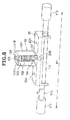
FIG. 8 , the diameter φ of thesupport shaft 17D supporting the fronttop rollers 17B may be arranged, preferably, to fall in the range from 8.5% to 11.5% inclusive of a distance P1 between the fronttop rollers 17B provided on the two ends of thesupport shaft 17D and may be arranged, more preferably, to fall in the range from 9.0% to 10.0% inclusive of the distance P1. The distance P1 between the fronttop rollers support shaft 17D denotes the distance between the centers of the fronttop rollers support shaft 17D in the axial direction. The diameter of each of thesupport shafts 14D to 16D can be equal to that of thesupport shaft 17D. - As shown in
FIG. 9 , therotation shaft 17C (a third rod member) supporting thefront bottom rollers 17A is supported with respect to themachine frame 62 via thebearings 117. Therotation shaft 17C is connected to the drivingmotor 120B arranged in thesecond end frame 5B and is driven by the drivingmotor 120B. Thebearings 117 are fixed to fixedparts 118 that are fixed to themachine frame 62. As a result, therotation shaft 17C is rotatably supported with respect to the fixedparts 118, i.e., themachine frame 62. - In the spinning machine 1 according to the present embodiment, the two bearings 117 (e.g., a bearing (a first bearing) 117A and another bearing (a second bearing) 117B) are positioned adjacent to each other in the axial direction of the
rotation shaft 17C. The number of the balls in thebearing 117A is different from the number of the balls in the bearing 117B. - Next, a driving control carried out with respect to the drafting rollers by the
main controlling device 55, which is one of the characteristic features of the present embodiment, will be explained, with reference toFIG. 10 . Themain controlling device 55 includes a Central Processing Unit (CPU), a Read-Only Memory (ROM), a Random Access Memory (RAM), and the like. As shown inFIG. 10 , themain controlling device 55 includes a prohibiting section (a controlling section) 55A and astorage section 55B, as conceptual parts that execute a controlling process with respect to the drafting rollers of the drafting devices 6. - The
main controlling device 55 receives a setting of a rotational speed of the drafting rollers from an operator via the input keys K. Thestorage section 55B stores therein the rotational speed of the drafting rollers per unit time, when the drafting rollers resonate with other members (e.g., thecradle 61, therotation shafts suction member 71, thebearings 117, and the like.). For example, when the drafting rollers and any of the other members resonate with each other while the drafting rollers are driven to rotate at a rotational speed of 433 m/min, the rotational speeds in the range of 433±α m/min can be stored in thestorage section 55B. - When a desired rotational speed is input by the operator via the input keys K, the prohibiting
section 55A checks whether the input value corresponds with a value stored in thestorage section 55B. When having confirmed that the input value corresponds with the value stored in thestorage section 55B, the prohibitingsection 55A controls the display section D so as to display that it is not possible to set the input rotational speed. On the contrary, when having confirmed that the input value does not correspond with the value stored in thestorage section 55B, the prohibitingsection 55A controls the driving motors (e.g., the drivingmotors - Advantageous effects of the drafting device 6 according to the above embodiments will be explained below. By using the drafting device 6 according to the present embodiment, it is possible to prevent the occurrence of resonance between the supporting members, which directly or indirectly support the drafting rollers, and the drafting rollers that may be caused by the rotation of the drafting rollers. As a result, it is possible to prevent degradation of the physical properties of the yarn.
- In the above embodiments, because the
lateral face 94 of thecradle 61 is reinforced by thetriangular rib 95 as shown inFIG. 7A , it is possible to reduce vibration of thecradle 61 caused by the rotation of thetop rollers cradle 61, which serves as a supporting member, and the drafting rollers that may be caused by the rotation of the drafting rollers. - In the above embodiments, the first reinforcing
parts 96 are formed on thelateral face 94 of thecradle 61, as shown inFIG. 7A . Each first reinforcingpart 96 extends in the direction that intersects the direction in which vibration is applied by thetop rollers parts 96 are arranged side by side along the direction in which the vibration is applied by thetop rollers cradle 61 in the direction in which the vibration is applied by thetop rollers cradle 61, which serves as a supporting member, and the drafting rollers that may be caused by the rotation of the drafting rollers. - In the above embodiments, the diameter φ of the
support shaft 17D is, as shown inFIG. 8 , arranged to fall in the range from 8.5% to 11.5% inclusive of the distance P1 between the fronttop rollers support shaft 17D. As a result, it is possible to prevent the occurrence of resonance between thesupport shaft 17D, which serves as a supporting member, and the drafting rollers (the fronttop rollers 17B) that may be caused by the rotation of the drafting rollers. - In the above embodiments, by arranging the
wave washer 109 between thecradle 61 and thepressing spring 102 as shown inFIG. 8 , it is possible to prevent the vibration transmitted from thesupport shaft 17D from being further transmitted to thecradle 61. As a result, it is possible to prevent the occurrence of resonance between thecradle 61, which serves as a supporting member, and the drafting rollers that may be caused by the rotation of the drafting rollers. - In the above embodiments, because the fixing
part 77 is reinforced by the third reinforcingpart 77B as shown inFIG. 5 , it is possible to reduce vibration of the fixingpart 77 that may be caused by the rotation of thetop rollers suction member 71, which serves as a supporting member, and the drafting rollers that may be caused by the rotation of the drafting rollers. - In the above embodiments, as shown in
FIG. 5 , the third reinforcingpart 77B protruding in the direction in which the vibration is applied by thetop rollers main surface 77A of the fixingpart 77. With this arrangement, it is possible to inhibit the vibration of the fixingpart 77 in the direction in which the vibration is applied by thetop rollers suction member 71, which serves as a supporting member, and the drafting rollers that may be caused by the rotation of the drafting rollers. - In the above embodiments, the bearing 117A and the bearing 117B are positioned adjacent to each other as shown in
FIG. 9 . The bearing 117A includes the balls of which the number is adjusted to be different from the number of the balls in the bearing 117B. As a result, it is possible to prevent the occurrence of resonance between thebearings 117, which serve as supporting members, and the drafting rollers that may be caused by the rotation of the drafting rollers. - In the above embodiments, it is prohibited to set the drafting rollers to be driven at such a rotational speed at which the drafting rollers may resonate with at least one of the supporting members such as the
cradle 61, thesupport shafts suction member 71, thebearings 117, and the like. With this arrangement, it is possible to prevent the occurrence of resonance between at least one of the supporting members such as thecradle 61, thesupport shafts suction member 71, thebearings 117, and the like and the drafting rollers that may be caused by the rotation of the drafting rollers. - Embodiments of the present invention have been explained above; however, the present invention is not to be limitedly interpreted to the above embodiments.
- In the above embodiments, the example is explained in which each of the drafting devices 6 includes the
cradle 61, thesupport shafts suction member 71, and thebearings 117, as the supporting members. Explained as examples of the resonance preventing structures are: thetriangular rib 95 and the first reinforcingparts 96 arranged on thelateral face 94 of thecover part 91 of thecradle 61, thesupport shafts pressing mechanism 100 provided with thewave washer 109, thesuction member 71 having the fixingpart 77 that has the third reinforcingpart 77B formed thereon, and thebearings - In the above embodiments, the example is explained in which the
main controlling device 55 carries out control so that such a rotational speed at which resonance may occur between the drafting rollers and at least one of the supporting members cannot be set as the rotational speed of the drafting rollers (the drafting roller pairs 14, 15, 16, and 17). However, the spinning units do not necessarily have to have this function. - In the above embodiments, the example is explained in which the
cover part 91 of thecradle 61 is formed by the metal plate; however, thecover part 91 can be formed with cast metal. When thecover part 91 is formed with cast metal, thecradle 61 becomes more stable because the weight of thecover part 91 increases. As a result, it is possible to prevent the occurrence of resonance between thecradle 61, which serves as a supporting member, and the drafting rollers that may be caused by the rotation of the drafting rollers. - In the above embodiments, the example is explained in which four roller pairs are arranged as the drafting rollers. However, more or less roller pairs, such as three pairs or five pairs may be arranged.
- In the above embodiments, the example is explained in which the
main controlling device 55 carries out the driving control with respect to the drafting rollers (the pairs of draftingrollers unit controller 50 or a controller arranged for each of the spinning units 2 may carry out such a driving control. - The air spinning device can further include a needle that is held by the fiber guiding member so as to protrude into the spinning chamber to prevent the twist of the fiber bundle from being transmitted to the upstream side of the air spinning device. Alternatively, instead of using such a needle, the air spinning device can be configured so that a downstream end part of the fiber guiding member prevents the twist of the fiber bundle from being transmitted to the upstream side of the air spinning device. Furthermore, in place of the configurations explained above, the air spinning device may include a pair of air jet nozzles each of which apply a twist in opposite directions.
- In each of the spinning units 2, the
yarn pooling device 11 has the function of pulling the yarn Y from theair spinning device 7. However, the yarn may be pulled from theair spinning device 7 by using a delivery roller and a nip roller. In a configuration where the yarn Y is pulled from theair spinning device 7 by using the delivery roller and the nip roller, a slack tube that absorbs slack of the yarn Y by using a suction air current or a mechanical compensator may be arranged in place of theyarn pooling device 11. - The spinning machine 1 is configured so that at least one of the bottom rollers in the drafting device 6 and the
traverse guide 23 are driven by the power supplied from thesecond end frame 5B (i.e., the driving power is shared among plural spinning units 2). However, the various components (e.g., the drafting device, the spinning device, the winding device, and the like) included in each of the spinning units 2 may be driven independently of the various components included in the other spinning units 2. - The
tension sensor 9 can be arranged upstream of the yarn monitoring device 8 in terms of the running direction of the yarn Y. Theunit controller 50 can be arranged for each spinning unit 2. The spinning units 2 each do not necessarily have to include thewaxing device 12, thetension sensor 9, and the yarn monitoring device 8. - Although
FIG. 1 illustrates the example in which the spinning machine 1 winds yarn Y into a cheese-shaped package P, the spinning machine 1 is also able to wind the yarn Y into a cone-shaped package. When the yarn Y is wound into a cone-shaped package, the yarn may slacken due to the traversing of the yarn. However, theyarn pooling device 11 is able to absorb the slack. - In the above embodiments, the example is explained in which the drafting device 6 is provided in the spinning machine 1. However, the drafting device 6 can be provided in any of other types of textile machines such as a ring spinning frame or a drawing frame.
- According to an aspect of the present invention, a drafting device that drafts a fiber bundle includes plural drafting rollers arranged in a direction in which the fiber bundle is conveyed, the drafting rollers being arranged as plural roller pairs, each roller pair having a top roller and a bottom roller opposing the top roller; a supporting member that supports the drafting rollers; and a resonance preventing structure that prevents occurrence of resonance between the drafting rollers and the supporting member that may be caused by rotation of the drafting rollers.
- The drafting device configured in this manner is able to prevent the occurrence of resonance between the supporting member, which directly or indirectly supports the drafting rollers, and the drafting rollers that may be caused by the rotation of the drafting rollers. As a result, it is possible to prevent degradation of the physical properties of the yarn.
- In the above drafting device, the supporting member can include a cradle that rotatably supports the top rollers.
- The drafting device configured in this manner is able to prevent the occurrence of resonance between the cradle, which serves as the supporting member, and the drafting rollers that may be caused by the rotation of the drafting rollers.
- In the above drafting device, the cradle can have a lateral face that is formed by applying bending processing to a plate-like member. The resonance preventing structure can be at least one of a rib that is formed in a region including a section to which the bending processing is applied, and first reinforcing parts each of which is formed by processing the lateral face and each of which extends in a direction intersecting axial directions of the top rollers and a direction in which the roller pairs are arranged, the first reinforcing parts being arranged side by side along the direction in which the roller pairs are arranged.
- In the drafting device configured in this manner, at least the lateral face of the cradle is reinforced by the rib or vibration of the cradle in the direction in which vibration is applied by the top rollers is inhibited by the first reinforcing parts formed on the lateral face of the cradle. As a result, it is possible to prevent the occurrence of resonance between the cradle, which serves as the supporting member, and the drafting rollers that may be caused by the rotation of the drafting rollers.
- In the above drafting device, the supporting member can include a first rod member that is supported by the cradle and that rotatably supports on two ends thereof, one of the top rollers and a top roller of an adjacent drafting device arranged adjacent to the drafting device in an axial direction of the top rollers, and the resonance preventing structure can be realized by a dimension of a diameter of the first rod member formed so as to fall in a range from 8.5% to 11.5% inclusive of a distance between the adjacent top rollers.
- As a result, it is possible to prevent the occurrence of resonance between the first rod member, which serves as the supporting member, and the drafting rollers that may be caused by the rotation of the drafting rollers.
- In the above drafting device, an elastic member that presses in a direction in which the bottom rollers are arranged a second rod member that rotatably supports the top rollers on two ends thereof can be arranged in the cradle, and the resonance preventing structure can be a damper arranged between the cradle and the elastic member.
- In the drafting device configured in this manner, the damper arranged between the cradle and the elastic member prevents vibration transmitted from the second rod member from being further transmitted to the cradle. As a result, it is possible to prevent the occurrence of resonance between the cradle, which serves as the supporting member, and the drafting rollers that may be caused by the rotation of the drafting rollers.
- In the above drafting device, the supporting member can include a suction member that includes a tubular part having a suction port arranged facing at least one of the drafting rollers; and a fixing part configured with a plate-like member for fixing the tubular part to the cradle that rotatably supports the top rollers. The resonance preventing structure can be at least one of a second reinforcing part formed by processing an external surface of the tubular part, and a third reinforcing part formed by processing the fixing part.
- In the drafting device configured in this manner, because at least one of the tubular part and the fixing part is reinforced by one or both of the second reinforcing part and the third reinforcing part, it is possible to reduce vibration of the tubular part and the fixing part that may be caused by the rotation of the top rollers. As a result, it is possible to prevent the occurrence of resonance between the suction member, which serves as the supporting member, and the drafting rollers that may be caused by the rotation of the drafting rollers.
- In the above drafting device, a main surface of the fixing part can be fixed to the cradle so as to intersect the direction in which the drafting roller is arranged.
- In the drafting device configured in this manner, vibration of the fixing part in the direction in which vibration is applied by the top rollers is inhibited. As a result, it is possible to prevent the occurrence of resonance between the suction member, which serves as the supporting member, and the drafting rollers that may be caused by the rotation of the drafting rollers.
- In the above drafting device, the supporting member can include a first bearing and a second bearing each of which rotatably supports a third rod member that supports the bottom rollers of one of the drafting rollers with respect to a machine frame. The first bearing and the second bearing can be positioned adjacent to each other, and the resonance preventing structure can be realized by adjusting number of balls in the second bearing to be different from number of balls in the first bearing.
- The drafting device configured in this manner is able to prevent the occurrence of resonance between the bearings, which serve as the supporting member, that may be caused by the rotation of the drafting rollers.
- According to another aspect of the present invention, a spinning unit includes the above drafting device; a spinning device that forms yarn by twisting the fiber bundle drafted by the drafting device; a winding device that winds the yarn supplied thereto from the spinning device into a package; and a controlling section that prohibits the drafting rollers from being driven at such a speed that causes the drafting rollers to resonate with the supporting member in the drafting device.
- In the spinning unit configured in this manner, the drafting rollers are prohibited from being driven at such a rotational speed that causes the drafting rollers to resonate with other supporting member such as the cradle, the first rod member, the second rod member, the suction member, the bearings, and the like. As a result, it is possible to prevent the occurrence of resonance between the supporting member and the drafting rollers that may be caused by the rotation of the drafting rollers.
- According to at least one aspect of the present invention, it is possible to prevent the physical properties of the yarn from being degraded. As for the physical properties of the "yarn" mentioned herein, the term "yarn" denotes not only yarn, but also fibers in a bundle form such as a sliver.
- In the above explanation, the meaning of "plural" also includes "a predetermined number of".
Claims (10)
- A drafting device (6) adapted to draft a fiber bundle (S), the draft device (6) comprising:plural drafting rollers (14A, 15A, 16A, 17A, 14B, 15B, 16B, 17B) arranged successively in a direction in which the fiber bundle (S) is conveyed, the drafting rollers (14A, 15A, 16A, 17A, 14B, 15B, 16B, 17B) being arranged as plural roller pairs (14, 15, 16, 17), each roller pair (14, 15, 16, 17) having a top roller (14A, 15A, 16A, 17A) and a bottom roller (14B, 15B, 16B, 17B) opposing the top roller (14A, 15A, 16A, 17A);a supporting member (61; 14D, 15D, 16D, 17D; 71; 117) adapted to support the drafting rollers (14A, 15A, 16A, 17A, 14B, 15B, 16B, 17B); anda resonance preventing structure (95; 96; 14D, 15D, 16D, 17D; 100; 71; 117A, 117B; 109) adapted to prevent occurrence of resonance between the drafting rollers (14A, 15A, 16A, 17A, 14B, 15B, 16B, 17B) and the supporting member (61; 14D, 15D, 16D, 17D; 71; 117) that may be caused by rotation of the drafting rollers (14A, 15A, 16A, 17A, 14B, 15B, 16B, 17B).
- The drafting device (6) as claimed in Claim 1, wherein the supporting member includes a cradle (61) adapted to rotatably support the top rollers (14A, 15A, 16A, 17A).
- The drafting device (6) as claimed in Claim 2, wherein
the cradle (61) has a lateral face (94) that is formed by applying bending processing to a plate-like member and extending between a top face (93) of the cradle (61) and an attachment part (92) of the cradle (61), wherein supporting structures (90) supporting the supporting member (61; 14D, 15D, 16D, 17D; 71; 117) are fixed to the attachment part (92), and
the resonance preventing structure is at least one of
a rib (95) that is formed in a region including a section to which the bending processing is applied, and
first reinforcing parts (96) each of which is formed by processing the lateral face (94) and each of which extends in a direction intersecting axial directions of the top rollers (14A, 15A, 16A, 17A) and a direction in which the roller pairs (14, 15, 16, 17) are arranged, the first reinforcing parts (96) being arranged side by side along the direction in which the roller pairs (14, 15, 16, 17) are arranged. - The drafting device (6) as claimed in Claim 2 or 3, wherein the supporting member includes a rod member (14D, 15D, 16D, 17D) supported by the cradle (61) and adapted to rotatably support on two ends thereof, one of the top rollers (14B, 15B, 16B, 17B) and a top roller (14B, 15B, 16B, 17B) of an adjacent drafting device (6) arranged adjacent to the drafting device (6) in an axial direction of the top rollers (14B, 15B, 16B, 17B), and
the resonance preventing structure is realized by a dimension of a diameter of the rod member (14D, 15D, 16D, 17D) formed so as to fall in a range from 8.5% to 11.5% inclusive of a distance between the adjacent top rollers (14B, 15B, 16B, 17B). - The drafting device (6) as claimed in claim 4, wherein the cradle (61) is provided with an elastic member (102) adapted to press the rod member (14D, 15D, 16D, 17D) such that the two top rollers (14B, 15B, 16B, 17B) are pressed against the respective opposing bottom rollers (14A, 15A, 16A, 17A), and
the resonance preventing structure comprises a damper (109) arranged between the cradle (61) and the elastic member (102). - The drafting device (6) as claimed in any one of Claims 2 and 3, further comprising a rod member (14D, 15D, 16D, 17D) adapted to rotatably support the top rollers (14B, 15B, 16B, 17B) on two ends thereof,
wherein the cradle (61) is provided with an elastic member (102) adapted to press the rod member (14D, 15D, 16D, 17D) such that the two top rollers (14B, 15B, 16B, 17B) are pressed against the respective opposing bottom rollers (14A, 15A, 16A, 17A), and
the resonance preventing structure is a damper (109) arranged between the cradle (61) and the elastic member (102). - The drafting device (6) as claimed in any one of Claims 2 to 6, wherein
the supporting member includes a suction member (71) that includes a tubular part (72) having a suction port (72A) arranged facing at least one of the drafting rollers (17B), and a fixing part (77) configured with a plate-like member for fixing the tubular part (72) to the cradle (61), and
the resonance preventing structure is at least one of a second reinforcing part formed by processing an external surface of the tubular part (72), and a third reinforcing part (77B) formed by processing the fixing part (77). - The drafting device (6) as claimed in Claim 7, wherein a main surface (77A) of the fixing part (77) is fixed to the cradle (61) so as to intersect the direction in which the drafting roller (14B, 15B, 16B, 17B) is arranged.
- The drafting device (6) as claimed in any one of Claims 1 to 8, wherein
the supporting member (117) includes a first bearing (117A) and a second bearing (117B) each of which rotatably supports a third rod member (17C) adapted to support the bottom rollers 17A) of one of the drafting rollers (14A, 15A, 16A, 17A) with respect to a machine frame (62),
the first bearing (117A) and the second bearing (117B) are positioned adjacent to each other, and
the resonance preventing structure is realized by adjusting a number of balls in the second bearing (117B) to be different from a number of balls in the first bearing (117A). - A spinning unit (2) comprising:the drafting device (6) as claimed in any one of Claims 1 to 9;a spinning device (7) adapted to form a yarn (Y) by twisting the fiber bundle (S, F) drafted by the drafting device (6);a winding device (13) adapted to wind the yarn (Y) supplied thereto from the spinning device (7) into a package (P); anda controlling section (50; 55) adapted to prohibit the drafting rollers (14A, 15A, 16A, 17A, 14B, 15B, 16B, 17B) from being driven at such a speed that causes the drafting rollers (14A, 15A, 16A, 17A, 14B, 15B, 16B, 17B) to resonate with the supporting member (61; 14D, 15D, 16D, 17D; 71; 117) in the drafting device (6).
Applications Claiming Priority (1)
| Application Number | Priority Date | Filing Date | Title |
|---|---|---|---|
| JP2014230926A JP2016094682A (en) | 2014-11-13 | 2014-11-13 | Draft machine and spinning unit |
Publications (2)
| Publication Number | Publication Date |
|---|---|
| EP3020854A1 true EP3020854A1 (en) | 2016-05-18 |
| EP3020854B1 EP3020854B1 (en) | 2019-08-14 |
Family
ID=54337698
Family Applications (1)
| Application Number | Title | Priority Date | Filing Date |
|---|---|---|---|
| EP15190812.6A Not-in-force EP3020854B1 (en) | 2014-11-13 | 2015-10-21 | Drafting device and spinning unit |
Country Status (3)
| Country | Link |
|---|---|
| EP (1) | EP3020854B1 (en) |
| JP (1) | JP2016094682A (en) |
| CN (2) | CN105603590B (en) |
Cited By (3)
| Publication number | Priority date | Publication date | Assignee | Title |
|---|---|---|---|---|
| EP3514275A1 (en) * | 2018-01-19 | 2019-07-24 | Murata Machinery, Ltd. | Merging structure for suction pipes, and yarn winding unit, spinning machine and textile machinery including the same |
| WO2021090137A1 (en) * | 2019-11-07 | 2021-05-14 | Rotorcraft Ag | Top arm for a spinning machine |
| EP4253617A1 (en) * | 2022-03-28 | 2023-10-04 | Maschinenfabrik Rieter AG | Suction of a combing position in a combing machine |
Families Citing this family (2)
| Publication number | Priority date | Publication date | Assignee | Title |
|---|---|---|---|---|
| JP2019148039A (en) | 2018-02-28 | 2019-09-05 | 村田機械株式会社 | Draft device and spinning unit |
| CN113493951B (en) * | 2020-03-20 | 2025-03-18 | 张家港市广大纺机有限公司 | A spinning machine cradle and fine-tuning pressure method |
Citations (7)
| Publication number | Priority date | Publication date | Assignee | Title |
|---|---|---|---|---|
| US2049322A (en) * | 1933-10-18 | 1936-07-28 | Parks Cramer Co | Method and apparatus for stabilizing the pressure of the drawing rolls of textile machinery |
| EP1731636A2 (en) * | 2005-06-06 | 2006-12-13 | Maschinenfabrik Rieter Ag | Support for a twin pressure roller of a drafting frame |
| EP2058421A2 (en) * | 2007-11-10 | 2009-05-13 | Oerlikon Accotex Texparts GmbH | Top roller carrying and loading arm |
| JP2010168690A (en) * | 2009-01-23 | 2010-08-05 | Murata Machinery Ltd | Drafting apparatus and textile machine |
| JP2011032618A (en) | 2009-08-05 | 2011-02-17 | Murata Machinery Ltd | Cleaning device for draft roller, draft machine, and textile machine |
| EP2570526A1 (en) * | 2011-09-13 | 2013-03-20 | Marzoli S.p.A. | Compacting device of a fibre web in a spinning frame |
| CN202913120U (en) * | 2012-11-25 | 2013-05-01 | 陈伟雄 | Upper roller bearing |
Family Cites Families (4)
| Publication number | Priority date | Publication date | Assignee | Title |
|---|---|---|---|---|
| GB726905A (en) * | 1952-01-30 | 1955-03-23 | Casablancas High Draft Co Ltd | Improvements in or relating to drafting mechanisms for textile fibres |
| JP2008297677A (en) * | 2007-06-01 | 2008-12-11 | Toyota Industries Corp | Fiber strand-guiding device in spinning machine |
| JP2008297676A (en) * | 2007-06-01 | 2008-12-11 | Toyota Industries Corp | Fiber strand-bundling apparatus in spinning machine |
| CH705307A1 (en) * | 2011-07-25 | 2013-01-31 | Rieter Ag Maschf | Spinning machine with a compacting device. |
-
2014
- 2014-11-13 JP JP2014230926A patent/JP2016094682A/en active Pending
-
2015
- 2015-10-21 EP EP15190812.6A patent/EP3020854B1/en not_active Not-in-force
- 2015-10-27 CN CN201510706435.2A patent/CN105603590B/en active Active
- 2015-10-27 CN CN201910654386.0A patent/CN110387606B/en active Active
Patent Citations (7)
| Publication number | Priority date | Publication date | Assignee | Title |
|---|---|---|---|---|
| US2049322A (en) * | 1933-10-18 | 1936-07-28 | Parks Cramer Co | Method and apparatus for stabilizing the pressure of the drawing rolls of textile machinery |
| EP1731636A2 (en) * | 2005-06-06 | 2006-12-13 | Maschinenfabrik Rieter Ag | Support for a twin pressure roller of a drafting frame |
| EP2058421A2 (en) * | 2007-11-10 | 2009-05-13 | Oerlikon Accotex Texparts GmbH | Top roller carrying and loading arm |
| JP2010168690A (en) * | 2009-01-23 | 2010-08-05 | Murata Machinery Ltd | Drafting apparatus and textile machine |
| JP2011032618A (en) | 2009-08-05 | 2011-02-17 | Murata Machinery Ltd | Cleaning device for draft roller, draft machine, and textile machine |
| EP2570526A1 (en) * | 2011-09-13 | 2013-03-20 | Marzoli S.p.A. | Compacting device of a fibre web in a spinning frame |
| CN202913120U (en) * | 2012-11-25 | 2013-05-01 | 陈伟雄 | Upper roller bearing |
Cited By (6)
| Publication number | Priority date | Publication date | Assignee | Title |
|---|---|---|---|---|
| EP3514275A1 (en) * | 2018-01-19 | 2019-07-24 | Murata Machinery, Ltd. | Merging structure for suction pipes, and yarn winding unit, spinning machine and textile machinery including the same |
| CN110055641A (en) * | 2018-01-19 | 2019-07-26 | 村田机械株式会社 | Attract the interflow construction of piping, have its Yarn reeling unit and spinning machinery |
| WO2021090137A1 (en) * | 2019-11-07 | 2021-05-14 | Rotorcraft Ag | Top arm for a spinning machine |
| CN114729473A (en) * | 2019-11-07 | 2022-07-08 | 罗托卡夫特公司 | Top arm for spinning machine |
| EP4253617A1 (en) * | 2022-03-28 | 2023-10-04 | Maschinenfabrik Rieter AG | Suction of a combing position in a combing machine |
| CH719552A1 (en) * | 2022-03-28 | 2023-10-13 | Rieter Ag Maschf | Combing machine with a suction. |
Also Published As
| Publication number | Publication date |
|---|---|
| JP2016094682A (en) | 2016-05-26 |
| CN105603590A (en) | 2016-05-25 |
| CN105603590B (en) | 2019-09-20 |
| EP3020854B1 (en) | 2019-08-14 |
| CN110387606B (en) | 2021-10-26 |
| CN110387606A (en) | 2019-10-29 |
Similar Documents
| Publication | Publication Date | Title |
|---|---|---|
| EP3020854B1 (en) | Drafting device and spinning unit | |
| EP3269851B1 (en) | Spinning machine | |
| EP2573216B1 (en) | Air-jet spinning machine and manufacturing method of spun yarn | |
| EP3025995A1 (en) | Yarn winding machine | |
| EP3075890B1 (en) | Draft device and spinning machine | |
| EP2284301A1 (en) | Cleaning device for draft roller, draft device, and textile machine | |
| CN210104152U (en) | Spinning machine | |
| EP3040458B1 (en) | Core yarn supplying device, spinning machine, and method of supplying core yarn | |
| JP2016023391A (en) | Spinning machine and spinning method | |
| CN108977945B (en) | Roller unit, draft device, and spinning machine | |
| CN103014952B (en) | Drafting system and spinning machinery | |
| EP3153613A1 (en) | Drafting device, spinning machine, and method of spinning technical field | |
| EP2975164B1 (en) | Spinning machine comprising a core yarn supplying unit. | |
| CN106687628B (en) | Equipment for producing core spun yarn | |
| EP2865795A1 (en) | Drafting device and spinning machine | |
| JP2018178311A (en) | Spinning machine, air spinning method, and yarn | |
| EP2452002B1 (en) | Device and method for making a core yarn | |
| JP2021110062A (en) | Draft device, spinning machine, spinning method, and draft roller | |
| EP2573229B1 (en) | Draft device and spinning machine | |
| CN112501729A (en) | Spinning unit, air spinning device, spinning machine and spinning method | |
| EP3150531A1 (en) | Yarn threading member, yarn storage device, and yarn winder | |
| JP2019007102A (en) | Air spinning device module, air spinning unit, and air spinning machine | |
| JP2025125958A (en) | Air spinning machine and suctioning/catching device | |
| JP2020133037A (en) | Cover for draft machine, draft machine and spinning machine | |
| JP2022027203A (en) | Draft machine and spinning unit |
Legal Events
| Date | Code | Title | Description |
|---|---|---|---|
| PUAI | Public reference made under article 153(3) epc to a published international application that has entered the european phase |
Free format text: ORIGINAL CODE: 0009012 |
|
| AK | Designated contracting states |
Kind code of ref document: A1 Designated state(s): AL AT BE BG CH CY CZ DE DK EE ES FI FR GB GR HR HU IE IS IT LI LT LU LV MC MK MT NL NO PL PT RO RS SE SI SK SM TR |
|
| AX | Request for extension of the european patent |
Extension state: BA ME |
|
| STAA | Information on the status of an ep patent application or granted ep patent |
Free format text: STATUS: REQUEST FOR EXAMINATION WAS MADE |
|
| 17P | Request for examination filed |
Effective date: 20161108 |
|
| RBV | Designated contracting states (corrected) |
Designated state(s): AL AT BE BG CH CY CZ DE DK EE ES FI FR GB GR HR HU IE IS IT LI LT LU LV MC MK MT NL NO PL PT RO RS SE SI SK SM TR |
|
| RIC1 | Information provided on ipc code assigned before grant |
Ipc: D01H 5/66 20060101ALI20181214BHEP Ipc: D01H 5/26 20060101AFI20181214BHEP Ipc: D01H 5/50 20060101ALI20181214BHEP Ipc: D01H 5/56 20060101ALI20181214BHEP Ipc: D01H 5/74 20060101ALI20181214BHEP |
|
| GRAP | Despatch of communication of intention to grant a patent |
Free format text: ORIGINAL CODE: EPIDOSNIGR1 |
|
| STAA | Information on the status of an ep patent application or granted ep patent |
Free format text: STATUS: GRANT OF PATENT IS INTENDED |
|
| INTG | Intention to grant announced |
Effective date: 20190225 |
|
| GRAS | Grant fee paid |
Free format text: ORIGINAL CODE: EPIDOSNIGR3 |
|
| GRAA | (expected) grant |
Free format text: ORIGINAL CODE: 0009210 |
|
| STAA | Information on the status of an ep patent application or granted ep patent |
Free format text: STATUS: THE PATENT HAS BEEN GRANTED |
|
| AK | Designated contracting states |
Kind code of ref document: B1 Designated state(s): AL AT BE BG CH CY CZ DE DK EE ES FI FR GB GR HR HU IE IS IT LI LT LU LV MC MK MT NL NO PL PT RO RS SE SI SK SM TR |
|
| REG | Reference to a national code |
Ref country code: GB Ref legal event code: FG4D |
|
| REG | Reference to a national code |
Ref country code: CH Ref legal event code: EP Ref country code: AT Ref legal event code: REF Ref document number: 1167149 Country of ref document: AT Kind code of ref document: T Effective date: 20190815 |
|
| REG | Reference to a national code |
Ref country code: IE Ref legal event code: FG4D |
|
| REG | Reference to a national code |
Ref country code: DE Ref legal event code: R096 Ref document number: 602015035724 Country of ref document: DE |
|
| REG | Reference to a national code |
Ref country code: CH Ref legal event code: NV Representative=s name: BOVARD AG PATENT- UND MARKENANWAELTE, CH |
|
| REG | Reference to a national code |
Ref country code: NL Ref legal event code: MP Effective date: 20190814 |
|
| REG | Reference to a national code |
Ref country code: LT Ref legal event code: MG4D |
|
| PG25 | Lapsed in a contracting state [announced via postgrant information from national office to epo] |
Ref country code: FI Free format text: LAPSE BECAUSE OF FAILURE TO SUBMIT A TRANSLATION OF THE DESCRIPTION OR TO PAY THE FEE WITHIN THE PRESCRIBED TIME-LIMIT Effective date: 20190814 Ref country code: HR Free format text: LAPSE BECAUSE OF FAILURE TO SUBMIT A TRANSLATION OF THE DESCRIPTION OR TO PAY THE FEE WITHIN THE PRESCRIBED TIME-LIMIT Effective date: 20190814 Ref country code: SE Free format text: LAPSE BECAUSE OF FAILURE TO SUBMIT A TRANSLATION OF THE DESCRIPTION OR TO PAY THE FEE WITHIN THE PRESCRIBED TIME-LIMIT Effective date: 20190814 Ref country code: NO Free format text: LAPSE BECAUSE OF FAILURE TO SUBMIT A TRANSLATION OF THE DESCRIPTION OR TO PAY THE FEE WITHIN THE PRESCRIBED TIME-LIMIT Effective date: 20191114 Ref country code: PT Free format text: LAPSE BECAUSE OF FAILURE TO SUBMIT A TRANSLATION OF THE DESCRIPTION OR TO PAY THE FEE WITHIN THE PRESCRIBED TIME-LIMIT Effective date: 20191216 Ref country code: LT Free format text: LAPSE BECAUSE OF FAILURE TO SUBMIT A TRANSLATION OF THE DESCRIPTION OR TO PAY THE FEE WITHIN THE PRESCRIBED TIME-LIMIT Effective date: 20190814 Ref country code: BG Free format text: LAPSE BECAUSE OF FAILURE TO SUBMIT A TRANSLATION OF THE DESCRIPTION OR TO PAY THE FEE WITHIN THE PRESCRIBED TIME-LIMIT Effective date: 20191114 Ref country code: NL Free format text: LAPSE BECAUSE OF FAILURE TO SUBMIT A TRANSLATION OF THE DESCRIPTION OR TO PAY THE FEE WITHIN THE PRESCRIBED TIME-LIMIT Effective date: 20190814 |
|
| REG | Reference to a national code |
Ref country code: AT Ref legal event code: MK05 Ref document number: 1167149 Country of ref document: AT Kind code of ref document: T Effective date: 20190814 |
|
| PG25 | Lapsed in a contracting state [announced via postgrant information from national office to epo] |
Ref country code: LV Free format text: LAPSE BECAUSE OF FAILURE TO SUBMIT A TRANSLATION OF THE DESCRIPTION OR TO PAY THE FEE WITHIN THE PRESCRIBED TIME-LIMIT Effective date: 20190814 Ref country code: ES Free format text: LAPSE BECAUSE OF FAILURE TO SUBMIT A TRANSLATION OF THE DESCRIPTION OR TO PAY THE FEE WITHIN THE PRESCRIBED TIME-LIMIT Effective date: 20190814 Ref country code: AL Free format text: LAPSE BECAUSE OF FAILURE TO SUBMIT A TRANSLATION OF THE DESCRIPTION OR TO PAY THE FEE WITHIN THE PRESCRIBED TIME-LIMIT Effective date: 20190814 Ref country code: GR Free format text: LAPSE BECAUSE OF FAILURE TO SUBMIT A TRANSLATION OF THE DESCRIPTION OR TO PAY THE FEE WITHIN THE PRESCRIBED TIME-LIMIT Effective date: 20191115 Ref country code: IS Free format text: LAPSE BECAUSE OF FAILURE TO SUBMIT A TRANSLATION OF THE DESCRIPTION OR TO PAY THE FEE WITHIN THE PRESCRIBED TIME-LIMIT Effective date: 20191214 Ref country code: RS Free format text: LAPSE BECAUSE OF FAILURE TO SUBMIT A TRANSLATION OF THE DESCRIPTION OR TO PAY THE FEE WITHIN THE PRESCRIBED TIME-LIMIT Effective date: 20190814 |
|
| PG25 | Lapsed in a contracting state [announced via postgrant information from national office to epo] |
Ref country code: TR Free format text: LAPSE BECAUSE OF FAILURE TO SUBMIT A TRANSLATION OF THE DESCRIPTION OR TO PAY THE FEE WITHIN THE PRESCRIBED TIME-LIMIT Effective date: 20190814 |
|
| PG25 | Lapsed in a contracting state [announced via postgrant information from national office to epo] |
Ref country code: EE Free format text: LAPSE BECAUSE OF FAILURE TO SUBMIT A TRANSLATION OF THE DESCRIPTION OR TO PAY THE FEE WITHIN THE PRESCRIBED TIME-LIMIT Effective date: 20190814 Ref country code: RO Free format text: LAPSE BECAUSE OF FAILURE TO SUBMIT A TRANSLATION OF THE DESCRIPTION OR TO PAY THE FEE WITHIN THE PRESCRIBED TIME-LIMIT Effective date: 20190814 Ref country code: PL Free format text: LAPSE BECAUSE OF FAILURE TO SUBMIT A TRANSLATION OF THE DESCRIPTION OR TO PAY THE FEE WITHIN THE PRESCRIBED TIME-LIMIT Effective date: 20190814 Ref country code: IT Free format text: LAPSE BECAUSE OF FAILURE TO SUBMIT A TRANSLATION OF THE DESCRIPTION OR TO PAY THE FEE WITHIN THE PRESCRIBED TIME-LIMIT Effective date: 20190814 Ref country code: AT Free format text: LAPSE BECAUSE OF FAILURE TO SUBMIT A TRANSLATION OF THE DESCRIPTION OR TO PAY THE FEE WITHIN THE PRESCRIBED TIME-LIMIT Effective date: 20190814 Ref country code: DK Free format text: LAPSE BECAUSE OF FAILURE TO SUBMIT A TRANSLATION OF THE DESCRIPTION OR TO PAY THE FEE WITHIN THE PRESCRIBED TIME-LIMIT Effective date: 20190814 |
|
| PG25 | Lapsed in a contracting state [announced via postgrant information from national office to epo] |
Ref country code: SK Free format text: LAPSE BECAUSE OF FAILURE TO SUBMIT A TRANSLATION OF THE DESCRIPTION OR TO PAY THE FEE WITHIN THE PRESCRIBED TIME-LIMIT Effective date: 20190814 Ref country code: SM Free format text: LAPSE BECAUSE OF FAILURE TO SUBMIT A TRANSLATION OF THE DESCRIPTION OR TO PAY THE FEE WITHIN THE PRESCRIBED TIME-LIMIT Effective date: 20190814 Ref country code: MC Free format text: LAPSE BECAUSE OF FAILURE TO SUBMIT A TRANSLATION OF THE DESCRIPTION OR TO PAY THE FEE WITHIN THE PRESCRIBED TIME-LIMIT Effective date: 20190814 Ref country code: IS Free format text: LAPSE BECAUSE OF FAILURE TO SUBMIT A TRANSLATION OF THE DESCRIPTION OR TO PAY THE FEE WITHIN THE PRESCRIBED TIME-LIMIT Effective date: 20200224 |
|
| REG | Reference to a national code |
Ref country code: DE Ref legal event code: R097 Ref document number: 602015035724 Country of ref document: DE |
|
| PLBE | No opposition filed within time limit |
Free format text: ORIGINAL CODE: 0009261 |
|
| STAA | Information on the status of an ep patent application or granted ep patent |
Free format text: STATUS: NO OPPOSITION FILED WITHIN TIME LIMIT |
|
| PG2D | Information on lapse in contracting state deleted |
Ref country code: IS |
|
| PG25 | Lapsed in a contracting state [announced via postgrant information from national office to epo] |
Ref country code: LU Free format text: LAPSE BECAUSE OF NON-PAYMENT OF DUE FEES Effective date: 20191021 |
|
| 26N | No opposition filed |
Effective date: 20200603 |
|
| REG | Reference to a national code |
Ref country code: BE Ref legal event code: MM Effective date: 20191031 |
|
| PG25 | Lapsed in a contracting state [announced via postgrant information from national office to epo] |
Ref country code: BE Free format text: LAPSE BECAUSE OF NON-PAYMENT OF DUE FEES Effective date: 20191031 Ref country code: SI Free format text: LAPSE BECAUSE OF FAILURE TO SUBMIT A TRANSLATION OF THE DESCRIPTION OR TO PAY THE FEE WITHIN THE PRESCRIBED TIME-LIMIT Effective date: 20190814 |
|
| GBPC | Gb: european patent ceased through non-payment of renewal fee |
Effective date: 20191114 |
|
| PG25 | Lapsed in a contracting state [announced via postgrant information from national office to epo] |
Ref country code: GB Free format text: LAPSE BECAUSE OF NON-PAYMENT OF DUE FEES Effective date: 20191114 Ref country code: FR Free format text: LAPSE BECAUSE OF NON-PAYMENT OF DUE FEES Effective date: 20191031 Ref country code: IE Free format text: LAPSE BECAUSE OF NON-PAYMENT OF DUE FEES Effective date: 20191021 |
|
| PGFP | Annual fee paid to national office [announced via postgrant information from national office to epo] |
Ref country code: CH Payment date: 20201021 Year of fee payment: 6 |
|
| PG25 | Lapsed in a contracting state [announced via postgrant information from national office to epo] |
Ref country code: CY Free format text: LAPSE BECAUSE OF FAILURE TO SUBMIT A TRANSLATION OF THE DESCRIPTION OR TO PAY THE FEE WITHIN THE PRESCRIBED TIME-LIMIT Effective date: 20190814 |
|
| PG25 | Lapsed in a contracting state [announced via postgrant information from national office to epo] |
Ref country code: MT Free format text: LAPSE BECAUSE OF FAILURE TO SUBMIT A TRANSLATION OF THE DESCRIPTION OR TO PAY THE FEE WITHIN THE PRESCRIBED TIME-LIMIT Effective date: 20190814 Ref country code: HU Free format text: LAPSE BECAUSE OF FAILURE TO SUBMIT A TRANSLATION OF THE DESCRIPTION OR TO PAY THE FEE WITHIN THE PRESCRIBED TIME-LIMIT; INVALID AB INITIO Effective date: 20151021 |
|
| REG | Reference to a national code |
Ref country code: CH Ref legal event code: PL |
|
| PG25 | Lapsed in a contracting state [announced via postgrant information from national office to epo] |
Ref country code: MK Free format text: LAPSE BECAUSE OF FAILURE TO SUBMIT A TRANSLATION OF THE DESCRIPTION OR TO PAY THE FEE WITHIN THE PRESCRIBED TIME-LIMIT Effective date: 20190814 |
|
| PG25 | Lapsed in a contracting state [announced via postgrant information from national office to epo] |
Ref country code: LI Free format text: LAPSE BECAUSE OF NON-PAYMENT OF DUE FEES Effective date: 20211031 Ref country code: CH Free format text: LAPSE BECAUSE OF NON-PAYMENT OF DUE FEES Effective date: 20211031 |
|
| PGFP | Annual fee paid to national office [announced via postgrant information from national office to epo] |
Ref country code: DE Payment date: 20221019 Year of fee payment: 8 Ref country code: CZ Payment date: 20221017 Year of fee payment: 8 |
|
| REG | Reference to a national code |
Ref country code: DE Ref legal event code: R119 Ref document number: 602015035724 Country of ref document: DE |
|
| PG25 | Lapsed in a contracting state [announced via postgrant information from national office to epo] |
Ref country code: CZ Free format text: LAPSE BECAUSE OF NON-PAYMENT OF DUE FEES Effective date: 20231021 |
|
| PG25 | Lapsed in a contracting state [announced via postgrant information from national office to epo] |
Ref country code: DE Free format text: LAPSE BECAUSE OF NON-PAYMENT OF DUE FEES Effective date: 20240501 Ref country code: CZ Free format text: LAPSE BECAUSE OF NON-PAYMENT OF DUE FEES Effective date: 20231021 |