EP3020357B1 - Dispositif de fabrication d'une prothèse dentaire - Google Patents
Dispositif de fabrication d'une prothèse dentaire Download PDFInfo
- Publication number
- EP3020357B1 EP3020357B1 EP14193333.3A EP14193333A EP3020357B1 EP 3020357 B1 EP3020357 B1 EP 3020357B1 EP 14193333 A EP14193333 A EP 14193333A EP 3020357 B1 EP3020357 B1 EP 3020357B1
- Authority
- EP
- European Patent Office
- Prior art keywords
- auxiliary element
- abutment
- forming device
- tooth replacement
- tube portion
- Prior art date
- Legal status (The legal status is an assumption and is not a legal conclusion. Google has not performed a legal analysis and makes no representation as to the accuracy of the status listed.)
- Active
Links
- 239000000853 adhesive Substances 0.000 claims description 31
- 230000001070 adhesive effect Effects 0.000 claims description 31
- 239000007943 implant Substances 0.000 claims description 15
- 239000000463 material Substances 0.000 claims description 9
- 238000000034 method Methods 0.000 claims description 4
- 239000005548 dental material Substances 0.000 claims description 3
- 238000004904 shortening Methods 0.000 claims description 3
- 239000000919 ceramic Substances 0.000 claims description 2
- 229920000642 polymer Polymers 0.000 claims description 2
- 238000003825 pressing Methods 0.000 claims description 2
- 238000007493 shaping process Methods 0.000 claims 2
- 239000013013 elastic material Substances 0.000 claims 1
- 239000003550 marker Substances 0.000 claims 1
- 230000007704 transition Effects 0.000 description 4
- 238000004026 adhesive bonding Methods 0.000 description 3
- 238000004519 manufacturing process Methods 0.000 description 3
- 230000002349 favourable effect Effects 0.000 description 2
- 239000002131 composite material Substances 0.000 description 1
- 238000011161 development Methods 0.000 description 1
- 230000018109 developmental process Effects 0.000 description 1
- 230000000694 effects Effects 0.000 description 1
- 239000002241 glass-ceramic Substances 0.000 description 1
- 230000014759 maintenance of location Effects 0.000 description 1
- 238000007669 thermal treatment Methods 0.000 description 1
Images


Classifications
-
- A—HUMAN NECESSITIES
- A61—MEDICAL OR VETERINARY SCIENCE; HYGIENE
- A61C—DENTISTRY; APPARATUS OR METHODS FOR ORAL OR DENTAL HYGIENE
- A61C13/00—Dental prostheses; Making same
- A61C13/0003—Making bridge-work, inlays, implants or the like
- A61C13/0006—Production methods
-
- A—HUMAN NECESSITIES
- A61—MEDICAL OR VETERINARY SCIENCE; HYGIENE
- A61C—DENTISTRY; APPARATUS OR METHODS FOR ORAL OR DENTAL HYGIENE
- A61C8/00—Means to be fixed to the jaw-bone for consolidating natural teeth or for fixing dental prostheses thereon; Dental implants; Implanting tools
- A61C8/0048—Connecting the upper structure to the implant, e.g. bridging bars
- A61C8/005—Connecting devices for joining an upper structure with an implant member, e.g. spacers
-
- A—HUMAN NECESSITIES
- A61—MEDICAL OR VETERINARY SCIENCE; HYGIENE
- A61C—DENTISTRY; APPARATUS OR METHODS FOR ORAL OR DENTAL HYGIENE
- A61C13/00—Dental prostheses; Making same
- A61C13/0003—Making bridge-work, inlays, implants or the like
- A61C13/0004—Computer-assisted sizing or machining of dental prostheses
-
- A—HUMAN NECESSITIES
- A61—MEDICAL OR VETERINARY SCIENCE; HYGIENE
- A61C—DENTISTRY; APPARATUS OR METHODS FOR ORAL OR DENTAL HYGIENE
- A61C13/00—Dental prostheses; Making same
- A61C13/20—Methods or devices for soldering, casting, moulding or melting
-
- A—HUMAN NECESSITIES
- A61—MEDICAL OR VETERINARY SCIENCE; HYGIENE
- A61C—DENTISTRY; APPARATUS OR METHODS FOR ORAL OR DENTAL HYGIENE
- A61C13/00—Dental prostheses; Making same
- A61C13/34—Making or working of models, e.g. preliminary castings, trial dentures; Dowel pins [4]
-
- A—HUMAN NECESSITIES
- A61—MEDICAL OR VETERINARY SCIENCE; HYGIENE
- A61C—DENTISTRY; APPARATUS OR METHODS FOR ORAL OR DENTAL HYGIENE
- A61C8/00—Means to be fixed to the jaw-bone for consolidating natural teeth or for fixing dental prostheses thereon; Dental implants; Implanting tools
- A61C8/0048—Connecting the upper structure to the implant, e.g. bridging bars
- A61C8/005—Connecting devices for joining an upper structure with an implant member, e.g. spacers
- A61C8/0054—Connecting devices for joining an upper structure with an implant member, e.g. spacers having a cylindrical implant connecting part
-
- A—HUMAN NECESSITIES
- A61—MEDICAL OR VETERINARY SCIENCE; HYGIENE
- A61C—DENTISTRY; APPARATUS OR METHODS FOR ORAL OR DENTAL HYGIENE
- A61C8/00—Means to be fixed to the jaw-bone for consolidating natural teeth or for fixing dental prostheses thereon; Dental implants; Implanting tools
- A61C8/0048—Connecting the upper structure to the implant, e.g. bridging bars
- A61C8/005—Connecting devices for joining an upper structure with an implant member, e.g. spacers
- A61C8/0066—Connecting devices for joining an upper structure with an implant member, e.g. spacers with positioning means
-
- A—HUMAN NECESSITIES
- A61—MEDICAL OR VETERINARY SCIENCE; HYGIENE
- A61C—DENTISTRY; APPARATUS OR METHODS FOR ORAL OR DENTAL HYGIENE
- A61C8/00—Means to be fixed to the jaw-bone for consolidating natural teeth or for fixing dental prostheses thereon; Dental implants; Implanting tools
- A61C2008/0084—Provisional implants or abutments
-
- A—HUMAN NECESSITIES
- A61—MEDICAL OR VETERINARY SCIENCE; HYGIENE
- A61C—DENTISTRY; APPARATUS OR METHODS FOR ORAL OR DENTAL HYGIENE
- A61C8/00—Means to be fixed to the jaw-bone for consolidating natural teeth or for fixing dental prostheses thereon; Dental implants; Implanting tools
- A61C8/0012—Means to be fixed to the jaw-bone for consolidating natural teeth or for fixing dental prostheses thereon; Dental implants; Implanting tools characterised by the material or composition, e.g. ceramics, surface layer, metal alloy
- A61C8/0016—Means to be fixed to the jaw-bone for consolidating natural teeth or for fixing dental prostheses thereon; Dental implants; Implanting tools characterised by the material or composition, e.g. ceramics, surface layer, metal alloy polymeric material
Definitions
- the invention relates to a tooth replacement production device according to the preamble of claim 1.
- Dentures are often fastened in a patient's mouth with the aid of an implant.
- the implant is typically provided with what is known as an abutment after it has been introduced, which is connected to the implant in a true-to-shape manner, for example by virtue of the fact that the mutually facing surfaces of the implant and abutment are non-round.
- the attachment itself is then carried out using an abutment screw that penetrates the abutment.
- an upper area of the abutment is designed as a pipe section, the inner diameter of which is sufficient to accommodate the abutment screw.
- the abutment screw rests somewhat below this pipe section on a mostly somewhat conical support area, the inner diameter of which is smaller than the head diameter of the abutment screw, through which, however, the shaft and the thread of the abutment screw fit.
- the implant then has, in a manner known per se, an internal thread for thread engagement with the thread of the abutment screw.
- a dental structure is then fastened on the abutment to the fastening of the abutment to the implant.
- the tube section or upper area of the abutment is usually slightly conical on the outside and fits true to shape into a corresponding recess in the dental structure.
- the invention is based on the object of creating a tooth replacement generating device according to the preamble of claim 1, which can be used better and universally, the restoration result also being improved, in particular with regard to the adhesion to the abutment.
- the abutment is present on its tube section with an outer radius that is not exceeded at any point.
- No anti-rotation spring protrudes into the auxiliary element, so that it is not weakened at this point.
- the pipe section is provided with a longitudinally parallel groove to provide the outside as a rotation protection element and the auxiliary element accordingly with an in particular optionally provided rotation protection spring that fits the groove.
- any desired rotational position can be adopted for the provision of a bridge as a dental restoration, and the desired automatic angle setting, as is the case with bridges, is guaranteed. It is also possible to manually remove the pre-made anti-rotation spring to achieve this effect.
- the wall thickness of the auxiliary element is uniform and, in particular, is not undershot at any point, so that it is not weakened.
- a wall thickness of 150 ⁇ m to 250 ⁇ m can be specified, and the auxiliary element - optionally with an industrially prefabricated, for example blasted surface - can be in close contact with the pipe section, with a clearance-free fit.
- the wall thickness of the auxiliary element can also be predominantly between 100 ⁇ m and 350 ⁇ m, preferably around 200 ⁇ m, at least apart from the areas in which a rotation lock is provided.
- the auxiliary element is prefabricated and accordingly has a preconditioned surface with a predetermined roughness, in particular both radially on the inside, that is to say towards the abutment, and radially on the outside.
- the auxiliary element preferably has a greater roughness on its radial outer surface than on its radial inner surface.
- the greater the roughness the lower the accuracy of fit. This applies both inside, i.e. towards the abutment, and outside, i.e. towards the superstructure. This roughness setting has the advantage for dental technicians that the auxiliary element no longer has to be re-assembled.
- the size dimensions of the auxiliary element and the abutment are selected so that the auxiliary element can be pushed onto the abutment, in particular also onto its pipe section, with a play-free fit.
- the adhesive joint between the superstructure or dental structure of the restoration and the abutment can be ensured in the desired quality with a correspondingly uniform wall thickness.
- a hard wax or even polyacrylic can be used as the material, and the industrially preconditioned outer surface of the auxiliary element also enables wax modeling and a secure connection of the wax modeling that may be desired if required.
- the adhesive gap or the adhesive joint preferably has a constant thickness. In the area of the collar of the abutment, however, it is preferred that the adhesive gap is reduced; this increases the accuracy of fit.
- the abutment has an adhesive receiving groove at a transition between its tube section and a circumferential collar, which in particular is formed circumferentially adjacent to the collar and that the auxiliary element has at least one projection, in particular a circumferential projection, which is intended for engagement in this groove.
- the gluing and modeling aid has a gripping handle which, when the gluing and modeling aid is inserted into the pipe section, extends above the pipe section.
- the bonding and modeling aid has a predetermined breaking point which extends in particular just above the pipe section of the abutment when the bonding and modeling aid is in the inserted state.
- the auxiliary element can preferably be shortened at predetermined heights.
- a starting height is provided, and markings for shortening to two further heights are advantageously provided, with the shortening particularly preferably taking place with a tool suitable for this purpose.
- the auxiliary element can be adapted to height-varying or classifiable abutments.
- the auxiliary element preferably has essentially the same wall thickness over its entire height. In the area of the tube section of the abutment, it thus extends downwards, precisely adapted to the length of this tube section, as far as the collar of the abutment.
- An inner shoulder of the auxiliary element is formed at the point at which the tube section of the abutment ends at an end face, and the inner and outer diameter of the auxiliary element jumps back from this point while maintaining the wall thickness.
- the length of the auxiliary element above the pipe section corresponds essentially to the length of the auxiliary element which rests on the abutment.
- this upper section of the auxiliary element preferably extends inside flush with the tube section of the abutment.
- the auxiliary element engages in this and to that extent has a correspondingly downward / inward-facing projection for engaging in this groove.
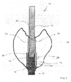
- the illustrated tooth replacement production device 10 has a dental structure 12 as a superstructure. This is mounted on an abutment 14 which is screwed onto an implant (not shown) in a manner known per se. Even if a single crown is shown here, it goes without saying that a dental bridge can also be implemented in an equivalent manner.
- the abutment has a collar 16 and a tube section 18.
- the pipe section 18 extends in a manner known per se with a constant wall thickness. At least one point it has a groove 20 to provide a rotation lock. This is in Fig. 1 to be seen there on the smaller wall thickness of the pipe section 18.
- an auxiliary element 22 is provided which extends with a constant wall thickness over the entire pipe section 18 and beyond.
- the auxiliary element 22 consists of a material that can be removed without residue, such as a polymer, and has an industrially preconditioned surface.
- the auxiliary element 22 is used to produce the dental restoration part, that is to say, for example, the preheating of a muffle in a preheating furnace when the dental restoration part is produced in a common pressing process, is removed without leaving any residue.
- Its wall thickness determines the thickness of an adhesive gap for bonding a superstructure to the abutment.
- the wall thickness of the auxiliary element 22 - and thus the adhesive gap - is between 0.01 mm and 0.5 mm, preferably less than 0.05 mm, and can be designed to be uniform over the course, but if necessary also change over the course.
- the auxiliary element 22 consists of a tubular holder section 24 and a tube section 26 with a smaller diameter in comparison, but the same wall thickness. At the transition between the holder section 24 and the tube section 26, an inner shoulder 28 is provided, the design of which matches an end face 30 of the tube section of the abutment 14.
- the auxiliary element 22 is self-retaining on the pipe section, so that it adheres in a force-fitting and / or form-fitting manner, the holding force preferably being less than 10 kN and more than 50N.
- the tube section 18 of the abutment 14 also has a number of depressions, in particular grooves 20, as an anti-twist device, which in particular engage with these projections of the auxiliary element 22 that are true to shape and are also referred to as springs.
- the number of projections of the auxiliary element 22 is less than or equal to the number of recesses 20 of the pipe section 18
- an adhesive and modeling aid 32 is provided, which is inserted into the pipe section 26 and partly also into the pipe section 18. It ends in a slight cone 34 and closes there tightly against the pipe section 18.
- the adhesive and modeling aid ensures that the interior of the abutment 14 is sealed tightly so that no material can inadvertently penetrate there that would impair access to the implant screw.
- the bonding and modeling aid 32 is securely inserted into the abutment due to its cone 34, but can be removed if necessary after it extends clearly upwards over the pipe section 26.
- the bonding and modeling aid 32 is preferably produced separately from the auxiliary element 22. However, a one-piece implementation is also possible.
- the auxiliary element 22 has, on its holder section 24, a radially inwardly projecting tongue 40 which is convex and fits to the groove 20 on the tube section 18 of the abutment 14.
- the holder portion 24 terminates in a flange 42 which projects radially outward and has an inner shape that matches a corresponding radius between the collar 16 and the tube portion 18 of the abutment 14.
- the extends Flange 42 by a small amount, such as 10 ⁇ m, beyond collar 16 to improve attachment.
- the material thickness or wall thickness of the auxiliary element 22 is preferably increased significantly, in particular approximately doubled, on the auxiliary element 22 at the point or locations at which a rotation lock is provided.
- the auxiliary element 22 has an inner radius 46 which matches the corresponding configuration on the end face 30 of the abutment. The auxiliary element thus rests on the abutment 14 over its entire surface and with an optimally uniformly low wall thickness.
- the gluing and modeling aid 32 here has a gripping handle 50 which, in the exemplary embodiment shown, is essentially sheet-shaped.
- a predetermined breaking point 52 is provided just below the gripping handle 50, at which the adhesive and modeling aid can be broken off if necessary.
- Your plug-in section 54 then completely fills the pipe section 18. Since the adhesive and modeling aid 32 also consists of a material that can be removed without leaving any residue, it can also be removed when the auxiliary element 22 is removed without leaving any residue.
- the adhesive and modeling aid 32 securely blocks the pipe section 18 against the ingress of foreign materials, so that access to the implant screw is always guaranteed.
- the auxiliary element preferably has a reference surface and / or a scannable marking, which and its position in space can be detected by a scanning device, which is in particular part of the CAD / CAM device.
- a scanning device which is in particular part of the CAD / CAM device.
- an auxiliary element identified by the scanning device - the wall thickness of which is known - can be used in the design of the adhesive gap by CAM.
- the CAD / CAM device based on the adhesive gap established by it, specifies an auxiliary element that can be identified via the marking, where the scanning of the marking allows checking whether the relevant auxiliary element is being used.
- the reference surfaces and / or markings are not only useful for designing the adhesive gap, but also serve in particular as a reference surface for the position of the abutment and / or rotation protection in connection with the patient situation.
- the larger this reference area the better and more accurate the scan comparison.
- the auxiliary element and / or the adhesive aid can be provided in one piece and / or in two pieces.
Claims (16)
- Dispositif de fabrication de prothèses dentaires, comprenant un élément auxiliaire (22), une structure dentaire (12) et un pilier (14), où une structure dentaire (12) en matériau dentaire, en particulier en céramique, est fabriquée à l'aide de procédés structurants ou ablatifs, en particulier au moyen de la FAO, et dans un procédé de pressage, où le pilier (14) peut être montée sur un implant au moyen d'une liaison amovible, en particulier d'une liaison vissée, où le pilier (14) présente une liaison d'implant, une collerette (16) et une section tubulaire (18) qui est destinée à être reliée à la structure dentaire (12), caractérisé en ce qu'un élément auxiliaire (22) fait d'un matériau combustible sans résidus est disposé adjacent à la section tubulaire (18) et autour de celle-ci, où l'élément auxiliaire est préfabriqué et présente par conséquent une surface avec une rugosité prédéterminée, où l'élément auxiliaire présente une plus grande rugosité sur sa surface radialement extérieure que sur sa surface radialement intérieure.
- Dispositif de fabrication de prothèses dentaires selon la revendication 1, caractérisé en ce que la partie tubulaire (18) du pilier (14) se rétrécit au niveau d'une surface d'extrémité (30) qui, lorsque l'élément auxiliaire (22) est inséré, vient en butée contre un épaulement intérieur de l'élément auxiliaire (22).
- Dispositif de fabrication de prothèses dentaires selon l'une quelconque des revendications précédentes, caractérisé en ce que l'élément auxiliaire (22) s'étend intérieurement à fleur de la surface intérieure de la partie tubulaire (18).
- Dispositif de fabrication de prothèses dentaires selon l'une des revendications précédentes, caractérisé en ce que la partie tubulaire (18) du pilier (14) présente, en tant que dispositif anti-rotation, un certain nombre de creux, en particulier des rainures (20), qui s'engagent en particulier dans des saillies de l'élément auxiliaire (22) correspondant à cette forme.
- Dispositif de fabrication de prothèses dentaires selon l'une des revendications précédentes, caractérisé en ce que l'élément auxiliaire (22), en particulier dans la zone recouvrant le tronçon tubulaire (18), présente une épaisseur de paroi de 0,01 mm à 0,5 mm, de préférence de 0,01 mm à 0,06 mm, qui correspond en particulier à un joint de collage, et en ce que le joint de collage peut être réalisé par calcination de l'élément auxiliaire.
- Dispositif de fabrication de prothèses dentaires selon l'une des revendications précédentes, caractérisé en ce que l'élément auxiliaire (22) adhère à la section tubulaire (18) par engagement solidaire de force et/ou de forme, où la force de maintien est inférieure à 10kN et supérieure à 50N.
- Dispositif de fabrication de prothèses dentaires selon l'une des revendications précédentes, caractérisé en ce que l'élément auxiliaire (22) est formé d'un matériau qui est plus souple que le matériau dentaire et que le pilier (14) mais plus élastique, en particulier d'un polymère qui peut être brûlé sans laisser de résidus.
- Dispositif de fabrication de prothèses dentaires selon l'une des revendications précédentes, caractérisé en ce que l'élément auxiliaire (22) présente une plus grande rugosité sur sa surface radiale extérieure que sur sa surface radiale intérieure.
- Dispositif de fabrication de prothèses dentaires selon l'une des revendications précédentes, caractérisé en ce que l'élément auxiliaire (22) présente une section tubulaire avec un diamètre extérieur plus petit et une section de support tubulaire (24) avec un diamètre extérieur plus grand par rapport à celui-ci, et en ce que la section tubulaire présente au moins la moitié de la longueur, de préférence de 80% à 150% de la longueur de la section de support (24).
- Dispositif de fabrication de prothèses dentaires selon l'une des revendications précédentes, caractérisé en ce que le pilier (14) présente une collerette périphérique (16) qui sépare une liaison d'implant et sa section tubulaire (18) et en ce que l'élément auxiliaire (22) se termine à la collerette (16), où en particulier une bride (42) à l'extrémité inférieure de l'élément auxiliaire (22) s'étend au-delà de la collerette (16) dans une faible mesure, comme par exemple 10 µm.
- Dispositif de fabrication de prothèses dentaires selon l'une des revendications précédentes, caractérisé en ce que le pilier (14) présente un cône (34) sur sa section tubulaire (18), en particulier avec un angle de cône compris entre 0,5° et 8°, et en ce que l'élément auxiliaire (22) présente sur sa section de support (24)un angle de cône adapté à celle-ci et/ou est amené à la forme de cône adaptée lorsqu'il est poussé sur la section tubulaire (18) de l'implant.
- Dispositif de fabrication de prothèses dentaires selon l'une des revendications précédentes, caractérisé en ce que l'élément auxiliaire (22) peut être raccourci dans une mesure prédéterminée pour correspondre au raccourcissement de la section tubulaire (18) du pilier (14), si nécessaire, et présente en particulier des marquages correspondants.
- Dispositif de fabrication de prothèses dentaires selon l'une des revendications précédentes, caractérisé en ce que l'élément auxiliaire (22) présente un élément anti-rotation qui s'étend parallèlement à l'axe de manière à faire saillie radialement vers l'intérieur et s'adapte dans au moins une rainure (20) de la section tubulaire (18) du pilier (14) afin de fournir un dispositif anti-rotation, où l'élément auxiliaire (22) présente, en particulier, un dispositif anti-rotation qui fait saillie vers l'intérieur, qui est conçu comme un ressort bombée et fait saillie radialement vers l'intérieur, en formant une convexité.
- Dispositif de fabrication de prothèses dentaires selon l'une des revendications précédentes, caractérisé en ce qu'un auxiliaire de collage et de modelage est prévu, qui s'adapte dans la section tubulaire (18) du pilier (14) et également dans l'élément auxiliaire (22) et qui ferme en particulier intérieurement la section tubulaire (18) pour fournir un cône (34).
- Dispositif de fabrication de prothèses dentaires selon l'une quelconque des revendications 15 à 17, caractérisé en ce que l'aide de collage et de modelage présente une section conique qui s'étend, en particulier sans filetage, dans la section tubulaire (18) du pilier (14).
- Dispositif de fabrication de prothèses dentaires selon l'une des revendications précédentes, caractérisé en ce que l'élément auxiliaire (22) présente une surface de référence et/ou un marquage pouvant être balayée, qui peut être détecté et dont la position dans l'espace peut être détectée par un dispositif de balayage qui fait en particulier partie du dispositif CAO/FAO.
Priority Applications (4)
| Application Number | Priority Date | Filing Date | Title |
|---|---|---|---|
| EP14193333.3A EP3020357B1 (fr) | 2014-11-14 | 2014-11-14 | Dispositif de fabrication d'une prothèse dentaire |
| ES14193333T ES2897694T3 (es) | 2014-11-14 | 2014-11-14 | Dispositivo de producción de prótesis dentales |
| US15/526,376 US10736719B2 (en) | 2014-11-14 | 2015-11-12 | Tooth replacement forming device, and method for forming a tooth replacement |
| PCT/EP2015/076456 WO2016075249A1 (fr) | 2014-11-14 | 2015-11-12 | Dispositif de réalisation de prothèse dentaire et procédé pour réaliser une prothèse dentaire |
Applications Claiming Priority (1)
| Application Number | Priority Date | Filing Date | Title |
|---|---|---|---|
| EP14193333.3A EP3020357B1 (fr) | 2014-11-14 | 2014-11-14 | Dispositif de fabrication d'une prothèse dentaire |
Publications (2)
| Publication Number | Publication Date |
|---|---|
| EP3020357A1 EP3020357A1 (fr) | 2016-05-18 |
| EP3020357B1 true EP3020357B1 (fr) | 2021-08-18 |
Family
ID=51897192
Family Applications (1)
| Application Number | Title | Priority Date | Filing Date |
|---|---|---|---|
| EP14193333.3A Active EP3020357B1 (fr) | 2014-11-14 | 2014-11-14 | Dispositif de fabrication d'une prothèse dentaire |
Country Status (4)
| Country | Link |
|---|---|
| US (1) | US10736719B2 (fr) |
| EP (1) | EP3020357B1 (fr) |
| ES (1) | ES2897694T3 (fr) |
| WO (1) | WO2016075249A1 (fr) |
Families Citing this family (4)
| Publication number | Priority date | Publication date | Assignee | Title |
|---|---|---|---|---|
| EP3583909B1 (fr) | 2014-05-27 | 2021-05-19 | Ivoclar Vivadent AG | Procédé de production d'une prothèse dentaire |
| US10639132B2 (en) * | 2014-09-12 | 2020-05-05 | Italo Lozada | Dental prosthesis |
| ES2737500B2 (es) * | 2018-07-06 | 2021-07-30 | Implant Protesis Dental 2004 S L | Conjunto para formar una pieza de interfase para implantes dentales con una altura variable |
| CH715768A2 (de) * | 2019-01-22 | 2020-07-31 | Z Systems Ag | Okklusalschraube, Dentalimplantatsystem und Set. |
Family Cites Families (13)
| Publication number | Priority date | Publication date | Assignee | Title |
|---|---|---|---|---|
| GB239103A (en) * | 1925-01-19 | 1925-09-03 | Columbus Dental Mfg Co | Improvements in interchangeable artificial teeth |
| US4431416A (en) | 1982-04-29 | 1984-02-14 | A & L Investment Company | Endosseous dental implant system for overdenture retention, crown and bridge support |
| DE3241963C1 (de) | 1982-11-12 | 1984-04-26 | Feldmühle AG, 4000 Düsseldorf | Schraubenfoermig ausgebildetes Kieferimplantat |
| US5613854A (en) * | 1995-04-17 | 1997-03-25 | Sweatt; Steven L. | Plastic sleeving to form dental coping and pontic and method |
| US5782918A (en) | 1996-12-12 | 1998-07-21 | Folsom Metal Products | Implant abutment system |
| DE10300301B4 (de) * | 2003-01-02 | 2009-07-02 | Sirona Dental Systems Gmbh | Verfahren zur automatischen Erzeugung einer dentalen Suprastruktur zur Verbindung mit einem Implantat |
| US20090317769A1 (en) * | 2006-11-14 | 2009-12-24 | Urdaneta Rainier A | Resilient coping for immediate loading of dental implants |
| EP1994908A1 (fr) * | 2007-05-21 | 2008-11-26 | Straumann Holding AG | Implant d'essai fonctionnel |
| JP4942120B2 (ja) * | 2008-11-17 | 2012-05-30 | 株式会社若吉製作所 | 医療用切削具の案内具 |
| US20120183925A1 (en) * | 2011-01-18 | 2012-07-19 | Gittleman Neal B | Dental Hydrostatic Relief Apparatus and Method |
| US8920170B2 (en) * | 2011-02-21 | 2014-12-30 | Aeton Medical Llc | Abutment and abutment systems for use with implants |
| WO2014081843A1 (fr) * | 2012-11-20 | 2014-05-30 | Advanced Implant Intellectual Properties, Llc | Système et procédés d'adaptateur d'alignement universel |
| JP2017506122A (ja) * | 2014-02-20 | 2017-03-02 | エムアイエス インプランツ テクノロジーズ リミテッド | 歯科インプラント |
-
2014
- 2014-11-14 EP EP14193333.3A patent/EP3020357B1/fr active Active
- 2014-11-14 ES ES14193333T patent/ES2897694T3/es active Active
-
2015
- 2015-11-12 US US15/526,376 patent/US10736719B2/en active Active
- 2015-11-12 WO PCT/EP2015/076456 patent/WO2016075249A1/fr active Application Filing
Non-Patent Citations (1)
| Title |
|---|
| None * |
Also Published As
| Publication number | Publication date |
|---|---|
| US20170312059A1 (en) | 2017-11-02 |
| ES2897694T3 (es) | 2022-03-02 |
| WO2016075249A1 (fr) | 2016-05-19 |
| US10736719B2 (en) | 2020-08-11 |
| EP3020357A1 (fr) | 2016-05-18 |
Similar Documents
| Publication | Publication Date | Title |
|---|---|---|
| EP1761196B1 (fr) | Implant dentaire a base d'oxyde de zirconium et procede pour produire un implant dentaire | |
| DE4028857C2 (fr) | ||
| EP3020357B1 (fr) | Dispositif de fabrication d'une prothèse dentaire | |
| EP2956083B1 (fr) | Agencement et système de prothèse dentaire | |
| DE102005027184B4 (de) | Modellimplantat für Zahnimplantate | |
| EP2509532B1 (fr) | Implant dentaire | |
| EP3583909B1 (fr) | Procédé de production d'une prothèse dentaire | |
| EP2114288A1 (fr) | Procédé concernant des implants, support lisible par ordinateur et ordinateur approprié | |
| EP3020358B1 (fr) | Méthode de production d'une prothèse dentaire | |
| EP2770943B1 (fr) | Prothèse dentaire comprenant un support métallique | |
| EP3212120B1 (fr) | Procédé de création d'un modèle d'élément prothétique dentaire | |
| EP3086737B1 (fr) | Ensemble formant prothèse dentaire | |
| EP3666224B1 (fr) | Prothèse dentaire pourvue de manchon de raccordement et kit | |
| WO2018059880A1 (fr) | Capuchon à fixer sur un élément d'ancrage | |
| WO2017097908A1 (fr) | Procédé pour produire des restaurations dentaires et dispositif de production de restaurations dentaires ainsi que corps de fraise | |
| DE102008037859A1 (de) | Kiefer-Implantat, Verfahren zu seiner Herstellung und seine Verwendung | |
| EP3545904B1 (fr) | Procédé de fabrication d'un modèle de travail à usage médico-dentaire à partir d'un moulage numérisé | |
| DE10337462B4 (de) | Verbindungsvorrichtung | |
| EP3829483B1 (fr) | Dispositif pour fixer et/ou pour soutenir la fixation d'une prothèse dentaire amovible sur une prothèse dentaire fixe | |
| DE102009008291A1 (de) | Abdruckkappe mit Abdruckpfosten für ein Zahnimplantat | |
| EP3340922B1 (fr) | Procédé et outil de fabrication d'un dispositif d'implant dentaire ainsi que dispositif d'implant dentaire ainsi fabriqué | |
| WO2010075993A1 (fr) | Capuchon d'empreinte avec pilier d'empreinte pour un implant dentaire | |
| WO2018228811A1 (fr) | Dispositif de fixation pour prothèse dentaire | |
| DE102012104071B4 (de) | Verbindungseinrichtung in einem Zahnersatz sowie Zahnersatz mit der Verbindungseinrichtung | |
| DE202008015181U1 (de) | Angulationsadapter |
Legal Events
| Date | Code | Title | Description |
|---|---|---|---|
| PUAI | Public reference made under article 153(3) epc to a published international application that has entered the european phase |
Free format text: ORIGINAL CODE: 0009012 |
|
| 17P | Request for examination filed |
Effective date: 20150814 |
|
| AK | Designated contracting states |
Kind code of ref document: A1 Designated state(s): AL AT BE BG CH CY CZ DE DK EE ES FI FR GB GR HR HU IE IS IT LI LT LU LV MC MK MT NL NO PL PT RO RS SE SI SK SM TR |
|
| AX | Request for extension of the european patent |
Extension state: BA ME |
|
| STAA | Information on the status of an ep patent application or granted ep patent |
Free format text: STATUS: EXAMINATION IS IN PROGRESS |
|
| 17Q | First examination report despatched |
Effective date: 20171102 |
|
| GRAP | Despatch of communication of intention to grant a patent |
Free format text: ORIGINAL CODE: EPIDOSNIGR1 |
|
| STAA | Information on the status of an ep patent application or granted ep patent |
Free format text: STATUS: GRANT OF PATENT IS INTENDED |
|
| INTG | Intention to grant announced |
Effective date: 20201002 |
|
| GRAS | Grant fee paid |
Free format text: ORIGINAL CODE: EPIDOSNIGR3 |
|
| GRAJ | Information related to disapproval of communication of intention to grant by the applicant or resumption of examination proceedings by the epo deleted |
Free format text: ORIGINAL CODE: EPIDOSDIGR1 |
|
| GRAL | Information related to payment of fee for publishing/printing deleted |
Free format text: ORIGINAL CODE: EPIDOSDIGR3 |
|
| STAA | Information on the status of an ep patent application or granted ep patent |
Free format text: STATUS: EXAMINATION IS IN PROGRESS |
|
| GRAP | Despatch of communication of intention to grant a patent |
Free format text: ORIGINAL CODE: EPIDOSNIGR1 |
|
| STAA | Information on the status of an ep patent application or granted ep patent |
Free format text: STATUS: GRANT OF PATENT IS INTENDED |
|
| INTC | Intention to grant announced (deleted) | ||
| RIN1 | Information on inventor provided before grant (corrected) |
Inventor name: BURGER, GORAN |
|
| GRAJ | Information related to disapproval of communication of intention to grant by the applicant or resumption of examination proceedings by the epo deleted |
Free format text: ORIGINAL CODE: EPIDOSDIGR1 |
|
| GRAL | Information related to payment of fee for publishing/printing deleted |
Free format text: ORIGINAL CODE: EPIDOSDIGR3 |
|
| INTG | Intention to grant announced |
Effective date: 20210302 |
|
| INTG | Intention to grant announced |
Effective date: 20210302 |
|
| GRAA | (expected) grant |
Free format text: ORIGINAL CODE: 0009210 |
|
| STAA | Information on the status of an ep patent application or granted ep patent |
Free format text: STATUS: THE PATENT HAS BEEN GRANTED |
|
| AK | Designated contracting states |
Kind code of ref document: B1 Designated state(s): AL AT BE BG CH CY CZ DE DK EE ES FI FR GB GR HR HU IE IS IT LI LT LU LV MC MK MT NL NO PL PT RO RS SE SI SK SM TR |
|
| REG | Reference to a national code |
Ref country code: GB Ref legal event code: FG4D Free format text: NOT ENGLISH |
|
| REG | Reference to a national code |
Ref country code: CH Ref legal event code: EP |
|
| REG | Reference to a national code |
Ref country code: DE Ref legal event code: R096 Ref document number: 502014015810 Country of ref document: DE |
|
| REG | Reference to a national code |
Ref country code: IE Ref legal event code: FG4D Free format text: LANGUAGE OF EP DOCUMENT: GERMAN Ref country code: AT Ref legal event code: REF Ref document number: 1420937 Country of ref document: AT Kind code of ref document: T Effective date: 20210915 |
|
| REG | Reference to a national code |
Ref country code: LT Ref legal event code: MG9D |
|
| REG | Reference to a national code |
Ref country code: NL Ref legal event code: MP Effective date: 20210818 |
|
| PG25 | Lapsed in a contracting state [announced via postgrant information from national office to epo] |
Ref country code: BG Free format text: LAPSE BECAUSE OF FAILURE TO SUBMIT A TRANSLATION OF THE DESCRIPTION OR TO PAY THE FEE WITHIN THE PRESCRIBED TIME-LIMIT Effective date: 20211118 Ref country code: LT Free format text: LAPSE BECAUSE OF FAILURE TO SUBMIT A TRANSLATION OF THE DESCRIPTION OR TO PAY THE FEE WITHIN THE PRESCRIBED TIME-LIMIT Effective date: 20210818 Ref country code: PT Free format text: LAPSE BECAUSE OF FAILURE TO SUBMIT A TRANSLATION OF THE DESCRIPTION OR TO PAY THE FEE WITHIN THE PRESCRIBED TIME-LIMIT Effective date: 20211220 Ref country code: NO Free format text: LAPSE BECAUSE OF FAILURE TO SUBMIT A TRANSLATION OF THE DESCRIPTION OR TO PAY THE FEE WITHIN THE PRESCRIBED TIME-LIMIT Effective date: 20211118 Ref country code: FI Free format text: LAPSE BECAUSE OF FAILURE TO SUBMIT A TRANSLATION OF THE DESCRIPTION OR TO PAY THE FEE WITHIN THE PRESCRIBED TIME-LIMIT Effective date: 20210818 Ref country code: HR Free format text: LAPSE BECAUSE OF FAILURE TO SUBMIT A TRANSLATION OF THE DESCRIPTION OR TO PAY THE FEE WITHIN THE PRESCRIBED TIME-LIMIT Effective date: 20210818 Ref country code: SE Free format text: LAPSE BECAUSE OF FAILURE TO SUBMIT A TRANSLATION OF THE DESCRIPTION OR TO PAY THE FEE WITHIN THE PRESCRIBED TIME-LIMIT Effective date: 20210818 Ref country code: RS Free format text: LAPSE BECAUSE OF FAILURE TO SUBMIT A TRANSLATION OF THE DESCRIPTION OR TO PAY THE FEE WITHIN THE PRESCRIBED TIME-LIMIT Effective date: 20210818 |
|
| PG25 | Lapsed in a contracting state [announced via postgrant information from national office to epo] |
Ref country code: PL Free format text: LAPSE BECAUSE OF FAILURE TO SUBMIT A TRANSLATION OF THE DESCRIPTION OR TO PAY THE FEE WITHIN THE PRESCRIBED TIME-LIMIT Effective date: 20210818 Ref country code: LV Free format text: LAPSE BECAUSE OF FAILURE TO SUBMIT A TRANSLATION OF THE DESCRIPTION OR TO PAY THE FEE WITHIN THE PRESCRIBED TIME-LIMIT Effective date: 20210818 Ref country code: GR Free format text: LAPSE BECAUSE OF FAILURE TO SUBMIT A TRANSLATION OF THE DESCRIPTION OR TO PAY THE FEE WITHIN THE PRESCRIBED TIME-LIMIT Effective date: 20211119 |
|
| REG | Reference to a national code |
Ref country code: ES Ref legal event code: FG2A Ref document number: 2897694 Country of ref document: ES Kind code of ref document: T3 Effective date: 20220302 |
|
| PG25 | Lapsed in a contracting state [announced via postgrant information from national office to epo] |
Ref country code: NL Free format text: LAPSE BECAUSE OF FAILURE TO SUBMIT A TRANSLATION OF THE DESCRIPTION OR TO PAY THE FEE WITHIN THE PRESCRIBED TIME-LIMIT Effective date: 20210818 |
|
| PG25 | Lapsed in a contracting state [announced via postgrant information from national office to epo] |
Ref country code: DK Free format text: LAPSE BECAUSE OF FAILURE TO SUBMIT A TRANSLATION OF THE DESCRIPTION OR TO PAY THE FEE WITHIN THE PRESCRIBED TIME-LIMIT Effective date: 20210818 |
|
| REG | Reference to a national code |
Ref country code: DE Ref legal event code: R097 Ref document number: 502014015810 Country of ref document: DE |
|
| PG25 | Lapsed in a contracting state [announced via postgrant information from national office to epo] |
Ref country code: SM Free format text: LAPSE BECAUSE OF FAILURE TO SUBMIT A TRANSLATION OF THE DESCRIPTION OR TO PAY THE FEE WITHIN THE PRESCRIBED TIME-LIMIT Effective date: 20210818 Ref country code: SK Free format text: LAPSE BECAUSE OF FAILURE TO SUBMIT A TRANSLATION OF THE DESCRIPTION OR TO PAY THE FEE WITHIN THE PRESCRIBED TIME-LIMIT Effective date: 20210818 Ref country code: RO Free format text: LAPSE BECAUSE OF FAILURE TO SUBMIT A TRANSLATION OF THE DESCRIPTION OR TO PAY THE FEE WITHIN THE PRESCRIBED TIME-LIMIT Effective date: 20210818 Ref country code: EE Free format text: LAPSE BECAUSE OF FAILURE TO SUBMIT A TRANSLATION OF THE DESCRIPTION OR TO PAY THE FEE WITHIN THE PRESCRIBED TIME-LIMIT Effective date: 20210818 Ref country code: CZ Free format text: LAPSE BECAUSE OF FAILURE TO SUBMIT A TRANSLATION OF THE DESCRIPTION OR TO PAY THE FEE WITHIN THE PRESCRIBED TIME-LIMIT Effective date: 20210818 Ref country code: AL Free format text: LAPSE BECAUSE OF FAILURE TO SUBMIT A TRANSLATION OF THE DESCRIPTION OR TO PAY THE FEE WITHIN THE PRESCRIBED TIME-LIMIT Effective date: 20210818 |
|
| PLBE | No opposition filed within time limit |
Free format text: ORIGINAL CODE: 0009261 |
|
| STAA | Information on the status of an ep patent application or granted ep patent |
Free format text: STATUS: NO OPPOSITION FILED WITHIN TIME LIMIT |
|
| PG25 | Lapsed in a contracting state [announced via postgrant information from national office to epo] |
Ref country code: MC Free format text: LAPSE BECAUSE OF FAILURE TO SUBMIT A TRANSLATION OF THE DESCRIPTION OR TO PAY THE FEE WITHIN THE PRESCRIBED TIME-LIMIT Effective date: 20210818 |
|
| 26N | No opposition filed |
Effective date: 20220519 |
|
| PG25 | Lapsed in a contracting state [announced via postgrant information from national office to epo] |
Ref country code: LU Free format text: LAPSE BECAUSE OF NON-PAYMENT OF DUE FEES Effective date: 20211114 Ref country code: BE Free format text: LAPSE BECAUSE OF NON-PAYMENT OF DUE FEES Effective date: 20211130 |
|
| REG | Reference to a national code |
Ref country code: BE Ref legal event code: MM Effective date: 20211130 |
|
| PG25 | Lapsed in a contracting state [announced via postgrant information from national office to epo] |
Ref country code: SI Free format text: LAPSE BECAUSE OF FAILURE TO SUBMIT A TRANSLATION OF THE DESCRIPTION OR TO PAY THE FEE WITHIN THE PRESCRIBED TIME-LIMIT Effective date: 20210818 |
|
| PG25 | Lapsed in a contracting state [announced via postgrant information from national office to epo] |
Ref country code: IE Free format text: LAPSE BECAUSE OF NON-PAYMENT OF DUE FEES Effective date: 20211114 |
|
| PG25 | Lapsed in a contracting state [announced via postgrant information from national office to epo] |
Ref country code: HU Free format text: LAPSE BECAUSE OF FAILURE TO SUBMIT A TRANSLATION OF THE DESCRIPTION OR TO PAY THE FEE WITHIN THE PRESCRIBED TIME-LIMIT; INVALID AB INITIO Effective date: 20141114 |
|
| PG25 | Lapsed in a contracting state [announced via postgrant information from national office to epo] |
Ref country code: CY Free format text: LAPSE BECAUSE OF FAILURE TO SUBMIT A TRANSLATION OF THE DESCRIPTION OR TO PAY THE FEE WITHIN THE PRESCRIBED TIME-LIMIT Effective date: 20210818 |
|
| P01 | Opt-out of the competence of the unified patent court (upc) registered |
Effective date: 20230607 |
|
| PGFP | Annual fee paid to national office [announced via postgrant information from national office to epo] |
Ref country code: GB Payment date: 20230928 Year of fee payment: 10 |
|
| PGFP | Annual fee paid to national office [announced via postgrant information from national office to epo] |
Ref country code: ES Payment date: 20231205 Year of fee payment: 10 |
|
| PGFP | Annual fee paid to national office [announced via postgrant information from national office to epo] |
Ref country code: IT Payment date: 20231115 Year of fee payment: 10 Ref country code: FR Payment date: 20231009 Year of fee payment: 10 Ref country code: DE Payment date: 20231017 Year of fee payment: 10 Ref country code: CH Payment date: 20231202 Year of fee payment: 10 Ref country code: AT Payment date: 20231004 Year of fee payment: 10 |