EP3020237B1 - Synchronizing peer-to-peer operation for outside network coverage and partial network coverage using lte air interface - Google Patents
Synchronizing peer-to-peer operation for outside network coverage and partial network coverage using lte air interface Download PDFInfo
- Publication number
- EP3020237B1 EP3020237B1 EP14822395.1A EP14822395A EP3020237B1 EP 3020237 B1 EP3020237 B1 EP 3020237B1 EP 14822395 A EP14822395 A EP 14822395A EP 3020237 B1 EP3020237 B1 EP 3020237B1
- Authority
- EP
- European Patent Office
- Prior art keywords
- synchronization
- synchronization signal
- signal
- ues
- group
- Prior art date
- Legal status (The legal status is an assumption and is not a legal conclusion. Google has not performed a legal analysis and makes no representation as to the accuracy of the status listed.)
- Active
Links
- 238000000034 method Methods 0.000 claims description 30
- 230000001360 synchronised effect Effects 0.000 claims description 29
- 230000004044 response Effects 0.000 claims description 9
- 230000001413 cellular effect Effects 0.000 claims description 8
- 238000012545 processing Methods 0.000 claims description 6
- 101001136811 Homo sapiens Salivary acidic proline-rich phosphoprotein 1/2 Proteins 0.000 description 70
- 102100036546 Salivary acidic proline-rich phosphoprotein 1/2 Human genes 0.000 description 70
- 238000004891 communication Methods 0.000 description 33
- 230000005540 biological transmission Effects 0.000 description 22
- 102100028850 Prolactin-releasing peptide Human genes 0.000 description 16
- 238000010586 diagram Methods 0.000 description 12
- 238000005259 measurement Methods 0.000 description 12
- 235000008694 Humulus lupulus Nutrition 0.000 description 11
- 238000001228 spectrum Methods 0.000 description 9
- 230000001419 dependent effect Effects 0.000 description 7
- 238000000638 solvent extraction Methods 0.000 description 7
- 238000005516 engineering process Methods 0.000 description 5
- 230000006870 function Effects 0.000 description 5
- 238000007726 management method Methods 0.000 description 5
- 238000013461 design Methods 0.000 description 4
- 101100099988 Arabidopsis thaliana TPD1 gene Proteins 0.000 description 3
- 101100352918 Saccharomyces cerevisiae (strain ATCC 204508 / S288c) PTC1 gene Proteins 0.000 description 3
- 230000007246 mechanism Effects 0.000 description 3
- 101100161168 Saccharomyces cerevisiae (strain ATCC 204508 / S288c) TPD3 gene Proteins 0.000 description 2
- 230000002776 aggregation Effects 0.000 description 2
- 238000004220 aggregation Methods 0.000 description 2
- 238000013459 approach Methods 0.000 description 2
- 238000003491 array Methods 0.000 description 2
- 125000004122 cyclic group Chemical group 0.000 description 2
- 230000007774 longterm Effects 0.000 description 2
- 238000013507 mapping Methods 0.000 description 2
- 238000010295 mobile communication Methods 0.000 description 2
- 230000008569 process Effects 0.000 description 2
- 230000008054 signal transmission Effects 0.000 description 2
- 241001193100 Idolothrips spectrum Species 0.000 description 1
- -1 TPD2 Proteins 0.000 description 1
- 238000013475 authorization Methods 0.000 description 1
- 230000006399 behavior Effects 0.000 description 1
- 230000008859 change Effects 0.000 description 1
- 230000001934 delay Effects 0.000 description 1
- 238000009795 derivation Methods 0.000 description 1
- 238000001514 detection method Methods 0.000 description 1
- 238000011161 development Methods 0.000 description 1
- 230000010354 integration Effects 0.000 description 1
- 239000004973 liquid crystal related substance Substances 0.000 description 1
- 230000003287 optical effect Effects 0.000 description 1
- 238000005457 optimization Methods 0.000 description 1
- 238000012913 prioritisation Methods 0.000 description 1
- 239000004065 semiconductor Substances 0.000 description 1
- 239000004557 technical material Substances 0.000 description 1
Images


Classifications
-
- H—ELECTRICITY
- H04—ELECTRIC COMMUNICATION TECHNIQUE
- H04J—MULTIPLEX COMMUNICATION
- H04J11/00—Orthogonal multiplex systems, e.g. using WALSH codes
- H04J11/0023—Interference mitigation or co-ordination
- H04J11/005—Interference mitigation or co-ordination of intercell interference
-
- H—ELECTRICITY
- H04—ELECTRIC COMMUNICATION TECHNIQUE
- H04W—WIRELESS COMMUNICATION NETWORKS
- H04W48/00—Access restriction; Network selection; Access point selection
- H04W48/18—Selecting a network or a communication service
-
- H—ELECTRICITY
- H04—ELECTRIC COMMUNICATION TECHNIQUE
- H04W—WIRELESS COMMUNICATION NETWORKS
- H04W56/00—Synchronisation arrangements
- H04W56/001—Synchronization between nodes
-
- H—ELECTRICITY
- H04—ELECTRIC COMMUNICATION TECHNIQUE
- H04W—WIRELESS COMMUNICATION NETWORKS
- H04W8/00—Network data management
- H04W8/005—Discovery of network devices, e.g. terminals
-
- H—ELECTRICITY
- H04—ELECTRIC COMMUNICATION TECHNIQUE
- H04L—TRANSMISSION OF DIGITAL INFORMATION, e.g. TELEGRAPHIC COMMUNICATION
- H04L5/00—Arrangements affording multiple use of the transmission path
- H04L5/0001—Arrangements for dividing the transmission path
- H04L5/0003—Two-dimensional division
- H04L5/0005—Time-frequency
- H04L5/0007—Time-frequency the frequencies being orthogonal, e.g. OFDM(A), DMT
-
- H—ELECTRICITY
- H04—ELECTRIC COMMUNICATION TECHNIQUE
- H04B—TRANSMISSION
- H04B15/00—Suppression or limitation of noise or interference
-
- H—ELECTRICITY
- H04—ELECTRIC COMMUNICATION TECHNIQUE
- H04J—MULTIPLEX COMMUNICATION
- H04J11/00—Orthogonal multiplex systems, e.g. using WALSH codes
-
- H—ELECTRICITY
- H04—ELECTRIC COMMUNICATION TECHNIQUE
- H04J—MULTIPLEX COMMUNICATION
- H04J3/00—Time-division multiplex systems
- H04J3/02—Details
- H04J3/06—Synchronising arrangements
- H04J3/0635—Clock or time synchronisation in a network
- H04J3/0638—Clock or time synchronisation among nodes; Internode synchronisation
-
- H—ELECTRICITY
- H04—ELECTRIC COMMUNICATION TECHNIQUE
- H04L—TRANSMISSION OF DIGITAL INFORMATION, e.g. TELEGRAPHIC COMMUNICATION
- H04L5/00—Arrangements affording multiple use of the transmission path
- H04L5/0001—Arrangements for dividing the transmission path
- H04L5/0003—Two-dimensional division
- H04L5/0005—Time-frequency
-
- H—ELECTRICITY
- H04—ELECTRIC COMMUNICATION TECHNIQUE
- H04L—TRANSMISSION OF DIGITAL INFORMATION, e.g. TELEGRAPHIC COMMUNICATION
- H04L5/00—Arrangements affording multiple use of the transmission path
- H04L5/003—Arrangements for allocating sub-channels of the transmission path
- H04L5/0048—Allocation of pilot signals, i.e. of signals known to the receiver
- H04L5/005—Allocation of pilot signals, i.e. of signals known to the receiver of common pilots, i.e. pilots destined for multiple users or terminals
-
- H—ELECTRICITY
- H04—ELECTRIC COMMUNICATION TECHNIQUE
- H04L—TRANSMISSION OF DIGITAL INFORMATION, e.g. TELEGRAPHIC COMMUNICATION
- H04L5/00—Arrangements affording multiple use of the transmission path
- H04L5/003—Arrangements for allocating sub-channels of the transmission path
- H04L5/0058—Allocation criteria
- H04L5/0073—Allocation arrangements that take into account other cell interferences
-
- H—ELECTRICITY
- H04—ELECTRIC COMMUNICATION TECHNIQUE
- H04W—WIRELESS COMMUNICATION NETWORKS
- H04W28/00—Network traffic management; Network resource management
- H04W28/02—Traffic management, e.g. flow control or congestion control
- H04W28/04—Error control
-
- H—ELECTRICITY
- H04—ELECTRIC COMMUNICATION TECHNIQUE
- H04W—WIRELESS COMMUNICATION NETWORKS
- H04W28/00—Network traffic management; Network resource management
- H04W28/02—Traffic management, e.g. flow control or congestion control
- H04W28/08—Load balancing or load distribution
- H04W28/09—Management thereof
-
- H—ELECTRICITY
- H04—ELECTRIC COMMUNICATION TECHNIQUE
- H04W—WIRELESS COMMUNICATION NETWORKS
- H04W4/00—Services specially adapted for wireless communication networks; Facilities therefor
- H04W4/70—Services for machine-to-machine communication [M2M] or machine type communication [MTC]
-
- H—ELECTRICITY
- H04—ELECTRIC COMMUNICATION TECHNIQUE
- H04W—WIRELESS COMMUNICATION NETWORKS
- H04W40/00—Communication routing or communication path finding
- H04W40/24—Connectivity information management, e.g. connectivity discovery or connectivity update
- H04W40/246—Connectivity information discovery
-
- H—ELECTRICITY
- H04—ELECTRIC COMMUNICATION TECHNIQUE
- H04W—WIRELESS COMMUNICATION NETWORKS
- H04W48/00—Access restriction; Network selection; Access point selection
-
- H—ELECTRICITY
- H04—ELECTRIC COMMUNICATION TECHNIQUE
- H04W—WIRELESS COMMUNICATION NETWORKS
- H04W48/00—Access restriction; Network selection; Access point selection
- H04W48/08—Access restriction or access information delivery, e.g. discovery data delivery
-
- H—ELECTRICITY
- H04—ELECTRIC COMMUNICATION TECHNIQUE
- H04W—WIRELESS COMMUNICATION NETWORKS
- H04W48/00—Access restriction; Network selection; Access point selection
- H04W48/16—Discovering, processing access restriction or access information
-
- H—ELECTRICITY
- H04—ELECTRIC COMMUNICATION TECHNIQUE
- H04W—WIRELESS COMMUNICATION NETWORKS
- H04W56/00—Synchronisation arrangements
- H04W56/001—Synchronization between nodes
- H04W56/002—Mutual synchronization
-
- H—ELECTRICITY
- H04—ELECTRIC COMMUNICATION TECHNIQUE
- H04W—WIRELESS COMMUNICATION NETWORKS
- H04W56/00—Synchronisation arrangements
- H04W56/004—Synchronisation arrangements compensating for timing error of reception due to propagation delay
- H04W56/0045—Synchronisation arrangements compensating for timing error of reception due to propagation delay compensating for timing error by altering transmission time
-
- H—ELECTRICITY
- H04—ELECTRIC COMMUNICATION TECHNIQUE
- H04W—WIRELESS COMMUNICATION NETWORKS
- H04W72/00—Local resource management
- H04W72/04—Wireless resource allocation
- H04W72/044—Wireless resource allocation based on the type of the allocated resource
-
- H—ELECTRICITY
- H04—ELECTRIC COMMUNICATION TECHNIQUE
- H04W—WIRELESS COMMUNICATION NETWORKS
- H04W72/00—Local resource management
- H04W72/04—Wireless resource allocation
- H04W72/044—Wireless resource allocation based on the type of the allocated resource
- H04W72/0453—Resources in frequency domain, e.g. a carrier in FDMA
-
- H—ELECTRICITY
- H04—ELECTRIC COMMUNICATION TECHNIQUE
- H04W—WIRELESS COMMUNICATION NETWORKS
- H04W72/00—Local resource management
- H04W72/12—Wireless traffic scheduling
- H04W72/1215—Wireless traffic scheduling for collaboration of different radio technologies
-
- H—ELECTRICITY
- H04—ELECTRIC COMMUNICATION TECHNIQUE
- H04W—WIRELESS COMMUNICATION NETWORKS
- H04W72/00—Local resource management
- H04W72/20—Control channels or signalling for resource management
- H04W72/21—Control channels or signalling for resource management in the uplink direction of a wireless link, i.e. towards the network
-
- H—ELECTRICITY
- H04—ELECTRIC COMMUNICATION TECHNIQUE
- H04W—WIRELESS COMMUNICATION NETWORKS
- H04W72/00—Local resource management
- H04W72/50—Allocation or scheduling criteria for wireless resources
- H04W72/54—Allocation or scheduling criteria for wireless resources based on quality criteria
- H04W72/541—Allocation or scheduling criteria for wireless resources based on quality criteria using the level of interference
-
- H—ELECTRICITY
- H04—ELECTRIC COMMUNICATION TECHNIQUE
- H04W—WIRELESS COMMUNICATION NETWORKS
- H04W80/00—Wireless network protocols or protocol adaptations to wireless operation
- H04W80/04—Network layer protocols, e.g. mobile IP [Internet Protocol]
-
- H—ELECTRICITY
- H04—ELECTRIC COMMUNICATION TECHNIQUE
- H04W—WIRELESS COMMUNICATION NETWORKS
- H04W84/00—Network topologies
- H04W84/18—Self-organising networks, e.g. ad-hoc networks or sensor networks
-
- H—ELECTRICITY
- H04—ELECTRIC COMMUNICATION TECHNIQUE
- H04W—WIRELESS COMMUNICATION NETWORKS
- H04W88/00—Devices specially adapted for wireless communication networks, e.g. terminals, base stations or access point devices
- H04W88/02—Terminal devices
-
- H—ELECTRICITY
- H04—ELECTRIC COMMUNICATION TECHNIQUE
- H04W—WIRELESS COMMUNICATION NETWORKS
- H04W84/00—Network topologies
- H04W84/02—Hierarchically pre-organised networks, e.g. paging networks, cellular networks, WLAN [Wireless Local Area Network] or WLL [Wireless Local Loop]
- H04W84/04—Large scale networks; Deep hierarchical networks
- H04W84/042—Public Land Mobile systems, e.g. cellular systems
-
- Y—GENERAL TAGGING OF NEW TECHNOLOGICAL DEVELOPMENTS; GENERAL TAGGING OF CROSS-SECTIONAL TECHNOLOGIES SPANNING OVER SEVERAL SECTIONS OF THE IPC; TECHNICAL SUBJECTS COVERED BY FORMER USPC CROSS-REFERENCE ART COLLECTIONS [XRACs] AND DIGESTS
- Y02—TECHNOLOGIES OR APPLICATIONS FOR MITIGATION OR ADAPTATION AGAINST CLIMATE CHANGE
- Y02D—CLIMATE CHANGE MITIGATION TECHNOLOGIES IN INFORMATION AND COMMUNICATION TECHNOLOGIES [ICT], I.E. INFORMATION AND COMMUNICATION TECHNOLOGIES AIMING AT THE REDUCTION OF THEIR OWN ENERGY USE
- Y02D30/00—Reducing energy consumption in communication networks
- Y02D30/70—Reducing energy consumption in communication networks in wireless communication networks
Definitions
- the present disclosure relates to direct device-to-device communication and, in particular, to outside network coverage and partial network coverage scenarios using Long Term Evolution (LTE) air interface for interference management and scheduling.
- LTE Long Term Evolution
- synchronous operation of two UEs is disclosed.
- One UE is connected to an eNB and communicates directly with a second UE.
- Multiple UEs in various synchronization clusters synchronize.
- Tthe UEs involved are able to elect one of the devices as the synchronization reference.
- a UE deriving synchronization from an NW is disclosed. Further, D2D discovery between UEs is disclosed.
- XP05069960 D2D communication between UEs is disclosed, including UEs being out of network coverage.
- Wireless mobile communication technology uses various standards and protocols to transmit data between a base station and a wireless communication device.
- Wireless communication system standards and protocols can include, for example, the 3rd Generation Partnership Project (3GPP) Long Term Evolution (LTE); the Institute of Electrical and Electronics Engineers (IEEE) 802.16 standard, which is commonly known to industry groups as worldwide interoperability for microwave access (WiMAX); and the IEEE 802.11 standard, which is commonly known to industry groups as Wi-Fi.
- 3GPP 3rd Generation Partnership Project
- LTE Long Term Evolution
- IEEE 802.16 Institute of Electrical and Electronics Engineers
- WiMAX worldwide interoperability for microwave access
- Wi-Fi IEEE 802.11 standard
- the base station can include Evolved Universal Terrestrial Radio Access Network (E-UTRAN) Node Bs (also commonly denoted as evolved Node Bs, enhanced Node Bs, eNodeBs, or eNBs), and/or Radio Network Controllers (RNCs) in an E-UTRAN, which communicate with a wireless communication device, known as user equipment (UE).
- E-UTRAN Evolved Universal Terrestrial Radio Access Network
- Node Bs also commonly denoted as evolved Node Bs, enhanced Node Bs, eNodeBs, or eNBs
- RNCs Radio Network Controllers
- LTE networks include radio access technology and core radio network architecture that provide high data rate, low latency, packet optimization, and improved system capacity and coverage.
- an E-UTRAN includes a plurality of eNodeBs and communicates with a plurality of UEs.
- a downlink (DL) transmission in an LTE network can be defined as a communication from the eNodeB to a UE, and an uplink (UL) transmission can be defined as a communication from the UE to the eNodeB.
- D2D device-to-device
- P2P peer-to-peer
- D2D has been proposed for local social networks, content sharing, location based marketing, serving advertisements, mobile to mobile applications, public safety, etc.
- D2D communications are of interest due to their ability to reduce load on a core network or access network, increase data rates due to direct and short communication paths, provide public safety communication paths, and provide other functionality.
- LTE technology defines fully synchronous operation between an eNodeB and UEs.
- a mobile terminal e.g., UE
- UE operation is configured by the eNodeB, and the UE terminal follows eNodeB instructions and commands in terms of spectrum resource management.
- Synchronous operation uses synchronization in absolute time among UE terminals or relative to the terminal providing the reference synchronization signals. Because it is already supported by UE terminals, the inventors of the present application have recognized that the extension of synchronous operation is a useful design choice for out of network coverage and partial network coverage scenarios. However, establishing synchronization for out of coverage scenarios is not a simple technical problem and may suffer from multiple sources of errors that can result in non-accurate synchronization.
- One of the challenges for example, is that public safety scenarios assume rather large incident areas where multiple first responder groups may operate simultaneously (e.g., in response to earthquake, forest fire, etc.). In this case, the synchronization may need to be established over a large geographical area using an air interface.
- a solution to establish common synchronization is to use a common reference source for all devices.
- Global Navigation Satellite System (GNSS) based solutions such as the Global Positioning System (GPS), Global Navigation Satellite System (GLONASS), Galileo, or Beidou, may be considered for providing a reliable reference source.
- GPS Global Positioning System
- GLONASS Global Navigation Satellite System
- Galileo Galileo
- Beidou Beidou
- methods are provided for enabling synchronous operation for out of coverage public safety specific scenarios.
- a system level solution is provided to reduce collision and synchronization errors among public safety terminals and establish synchronous operation over large geographical areas.
- public safety scenarios are provided by way of example only, and that the disclosed embodiments may be used in any number of scenarios, including commercial, government, and private use scenarios.
- Synchronous operation provides for capacity, energy efficiency, and long range communication ability, which are useful for public safety.
- dense ad-hoc networks that are typical for the public safety specific use cases, the communication rate and range is often limited by interference from multiple transmission points that are not synchronized to each other. The lack of synchronization creates strong mutual interference to intended receivers.
- asynchronous networks are not power efficient because terminals may need to continuously or frequently monitor the medium in order to receive a signal in which the transmission time is unknown a priori.
- a synchronization protocol may be used to establish synchronous operation of mobile public safety terminals in proximity areas for out of coverage and partial coverage scenarios.
- one or more public safety devices referred to herein as peer radio heads (PRH) or D2D synchronization sources, play the role of the synchronization reference for the remaining terminals in the surrounding area.
- PRH peer radio heads
- D2D synchronization sources may facilitate maintaining the synchronous operation in the neighboring geographical areas and provide synchronous or quasi-synchronous operation over large geographical areas.
- the protocol may also facilitate the collision free communication among multiple public safety groups (broadcast and groupcast) operating close to each other and distributed over large incident areas to perform their public safety missions.
- the synchronization protocol ensures that neighboring proximity areas operate synchronously by using a local synchronization protocol with hierarchical timing propagation.
- the example public safety use cases assume multiple direct groupcast and/or broadcast transmissions among the public safety terminals serving in a particular incident area. There may be multiple public safety groups that work in nearby or even the same geographical area and that may need to have reliable communication between each other as well as reliable discovery of each other or even members of the other groups.
- the LTE system bandwidth is divided into multiple frequency subchannels (frequency sub-bands), which can be used for data transmission and by default owned (i.e., reserved) by the members of the particular public safety group.
- one or more of the public safety specific devices serve as a synchronization reference point that broadcasts synchronization signals in order to establish synchronous operation and provide energy savings for terminals that belong to the particular public safety group(s) served by given PRH(s).
- a UE e.g., configured as a PRH or synchronization source
- UL uplink
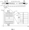
- FIG. 1 is a block diagram illustrating example UL spectrum resource partitioning for peer-to-peer synchronization according to one embodiment.
- This example is provided for frequency division multiplexing (FDM) embodiments.
- FDM frequency division multiplexing
- TDM time division multiplexing
- a plurality of UL frames 110 includes synchronization (sync) frames 112, 114 at a predetermined sync frame period.
- the sync frames 112, 114 are each divided into a plurality of UL subframes 116.
- each UL frame 110 has a duration of 10 milliseconds (ms)
- the start of the sync frames are separated in time by 80 ms (e.g., the sync frame period is 80 ms)
- each subframe has a duration of 1 ms. Skilled persons will recognize, however, that other frame durations, sync frame periods, and subframe durations may also be used.
- the LTE system bandwidth is divided into N logical frequency subchannels 118.
- the spectrum resources can be divided into time subchannels or time-frequency subchannels.
- a synchronization signal (sync signal) 120 is included within one of the frequency subchannels.
- frequency subchannel #3 includes the sync signal 120.
- each logical frequency subchannel 118 is composed from multiple (M) physical resource blocks (PRBs).
- PRBs physical resource blocks
- the resources may be divided into time slots, subframes or frames instead of frequency subchannels. In other embodiments, a combination of both frequency subchannels and time slots or subframes may be used.
- the FDM partitioning of the resources is more advantageous than TDM partitioning because operation of multiple public safety groups within the neighboring areas may happen to be non-synchronized.
- the FDM partitioning may reduce interference (collision) as compared to the TDM alternative in case of asynchronous areas.
- the sub-channelization gain can be extracted when the terminal transmits at maximum power in the subset of the overall frequency resources.
- logical frequency channel is used here to indicate that actual mapping of logical frequency resources to physical resource elements of the LTE system may be subject to any resource permutation or resource hopping function, although the orthogonality of physical resources is still preserved.
- a function of a PRH device or a synchronization source is to establish a local synchronization area within a given radius (determined by transmission range of the synchronization signal 120).
- the public safety terminals (UEs) that are within synchronization range can receive the synchronization signal 120 from the given PRH or synchronization source and establish a common timing reference so that their subsequent transmissions and/or operations are aligned in time and frequency. Therefore, terminals can achieve synchronization in time and frequency and thus synchronous communication becomes feasible.
- the established synchronization can be used by upper layer protocols for capacity and energy efficient transmission.
- the transmission period of the synchronization signal 120 is a tradeoff between clock drift (frequency stability) and power consumption. More accurate (stable) oscillators installed in the public safety devices may require longer sync frame periods. From the physical layer perspective, the sync frame period may be selected to keep the synchronization error within a small part of the cyclic prefix (CP) duration (e.g., 1/8 or 1/4 of CP time) to prevent asynchronous interference. At the same time, small sync frame periods increase the power consumption because the PRHs and other public safety terminals would need to more frequently monitor the transmission of the synchronization signal 120. In order to balance these two factors, the synchronization signal 120 can be transmitted periodically once per L frames.
- CP cyclic prefix
- the frame where the synchronization signal 120 is transmitted is called a synchronization frame 112.
- the synchronization signal 120 may be transmitted in the set of subframes 116 of the synchronization frame 112.
- L 8 LTE frames.
- the synchronization procedure described above assumes synchronization at the physical layer so that multiple concurrent transmissions within given geographical area do not cause inter-carrier interference, appearing when transmissions are not time aligned.
- the synchronization requirement may be relaxed such as to achieve synchronization at the upper layers only, but admit asynchronous transmissions from the physical layer perspective. In the latter case, the synchronization error requirements may be relaxed substantially.
- certain embodiments also orthogonalize transmission of the synchronization signal 120 in frequency, in time, or in both frequency and time domains.
- the orthogonalization in time can facilitate simple synchronization techniques between multiple PRHs (i.e., between multiple synchronization sources).
- the orthogonalization in frequency can facilitate more reliable transmission and interference management.
- the frequency channel for synchronization signal transmission can be either pre-configured or selected by the PRH or synchronization source during the scanning procedure. In embodiments of the latter case, the PRH or synchronization source scans all available frequency channels before establishing its own synchronization in a particular frequency channel.
- the PRH or synchronization source selects the frequency channel where the received power of a synchronization signal (e.g., from another synchronization source) has a minimum value or where a synchronization signal is not detectable.
- the PRH or synchronization source can select the time or time-frequency subchannel when executing a scanning procedure.
- the scanning may be simplified since the terminal does not need to scan multiple frequencies. However, if there is not enough time resources, the additional frequency dimension can be used to further improve performance.
- the PRH or synchronization source may select the frequency subchannel which is least congested from its receiver perspective. Note that once the synchronization channel is selected, the spectrum resources of this logical frequency channel are associated with or owned (i.e., reserved) by given PRH node or synchronization source.
- the division of frequency subchannels enables collision free operation when multiple PRHs or synchronization sources establish synchronization areas in geographically overlapping regions. Depending on the scenario, there may be a plurality of PRHs or synchronization sources detectable in a given area. In this case, the remaining non-occupied resources may be shared between deployed PRHs or synchronization sources. Certain embodiments use non-default frequency subchannels to increase throughput for D2D operation within the given synchronization area and at the same time control interference between devices that belong to different synchronization areas. In certain embodiments, a UE may autonomously select itself (i.e., self-configuration) to act as a PRH or synchronization source based on detection of synchronization signals (and/or lack thereof).
- an autonomous selection and reselection of mobile synchronization sources may be used.
- an eNodeB may assign UEs to serve as PRHs or synchronization sources.
- each PRH or synchronization source establishes its own local synchronization area to provide common reference timing for multiple devices (UEs) located within its synchronization range, and thus associated to the PRH or synchronization source.
- UEs e.g., public safety terminals
- the term “associated” means that UEs (e.g., public safety terminals) follow the synchronization signal transmitted by a given PRH or synchronization source, and use a derived timing based on the synchronization signal for their own operation.
- the term “associated” means that UEs (e.g., public safety terminals) perform an access procedure, and that the PRH or synchronization source assists in radio resource management functions as well.
- FIGS. 2A, 2B, and 2C are block diagrams illustrating non-overlapped 210, partially overlapped 212, and overlapped 214 scenarios that may result from the described synchronization protocol according to certain embodiments.
- a first synchronization area 216 includes a first UE 218 configured as (e.g., autonomously selected or self-configured as) a synchronization source (PRH1) to provide a synchronization signal to a first group of UEs 220
- a second synchronization area 222 includes a second UE 224 configured as (e.g., autonomously selected or self-configured as) a synchronization source (PRH2) to provide synchronization signals to a second group of UEs 226.
- PRH1 synchronization source
- PRH2 synchronization source
- FIG. 2A shows non-overlapped 210 synchronization areas 216, 222, wherein PRH1 is not synchronized in time with PRH2. Accordingly, the first synchronization area 216 and the second synchronization area 222 are asynchronous with one another. Further, in the non-overlapped 210 case, there are no UEs 220, 226 that can synchronize to both PRH1 and PRH2.
- FIG. 2B shows partially overlapped 212 synchronization areas 216, 222, wherein PRH1 is also not synchronized in time with PRH2 (as in FIG. 2A ). Accordingly, the first synchronization area 216 and the second synchronization area 222 are asynchronous with one another.
- UEs 220(a) and 226(a) within an overlapped region of synchronization areas 216 and 222 can detect synchronization signals from both PRH1 and PRH2 and are able to synchronize to either of them.
- the UEs 220(a) and 226(a) within the overlapped region can also facilitate establishment of synchronization between PRH1 and PRH2, if required or configured to do so.
- the UE 220(a) and/or the UE 226(a) can request either PRH1 or PRH2 to change frequency channels to avoid resource collisions and strong interference during the data transmission.
- the UE 220(a) or the UE 226(a) can transmit its own synchronization signals using the timing of one of the selected PRHs (PRH1 or PRH2), and thus can facilitate establishment of common synchronization between PRH1 and PRH2.
- FIG. 2C shows overlapped 214 synchronization areas 216, 222, wherein both PRH1 and PRH2 can detect and synchronize to each other to thereby establish a common reference source.
- the first synchronization area 216 and the second synchronization area 222 may become synchronous with each other. In certain embodiments, as discussed below, this is done by selecting one of PRH1 or PRH2 as a common reference source.
- the PRHs or synchronization sources can establish common timing by selecting one of the PRHs or synchronization sources as a common synchronization source. In this case, after a re-synchronization procedure, the whole extended area (i.e., both synchronization areas) operates synchronously.
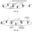
- FIGS. 3A and 3B are block diagrams illustrating extension of a synchronization area 310 according to one embodiment.
- the synchronization area 310 includes a UE 312 configured as (e.g., autonomously selected or self-configured as) a synchronization source (PRH1) to provide a first synchronization signal to a group of UEs 314, 316.
- PRH1 synchronization source
- FIG. 3A a UE 318 is located outside of the synchronization area 310. In other words, the UE 318 is beyond the range of receiving the first synchronization signal from PRH1.
- the UE 316 within the synchronization area 310 is configured to detect the UE 318 outside synchronization area 310, and the UE 316 responds by notifying PRH1 of the presence of the UE 318.
- the UE 316 may receive a request from the UE 318 to join the group of UEs 312, 314, 316, and the UE 316 forwards the request to PRH1.
- PRH1 sends a request 320 to the UE 316 to synchronize itself based on the first synchronization signal received on a first frequency subchannel (frequency subchannel #1) or time slot and to start transmission of the synchronization signal in a second frequency subchannel (frequency subchannel #2) or time slot.
- the UE 316 responds to the request by transmitting a second synchronization signal in the same synchronization frame as the first synchronization signal received from PRH1.
- the UE 316 becomes a D2D synchronization source (PRH2) that extends the synchronization area 310 to the UE 318, as shown in FIG. 3B .
- PRH2 derives synchronization (timing) for the second synchronization signal from the first synchronization signal received from PRH1.
- the UE 318 uses the second synchronization signal received from PRH2 to synchronize with the group of UEs 312, 314, 316.
- the number of hops i.e., propagation of timing information from one PRH to another
- synchronization timing error accumulates from hop to hop. This may be illustrated in two example embodiments where timing propagation is based on time of arrival measurements or round trip time measurements.
- a PRH propagates synchronization timing information by measuring the time of arrival of a synchronization signal from another node.
- the estimated time of arrival is used as the timing instance relative to which the PRH transmits its own synchronization signals.
- FIG. 4A includes a block diagram 410 and timing graph 412 illustrating timing propagation based on time of arrival measurements according to one embodiment.
- a first UE 414 is configured as (e.g., autonomously selected or self-configured as) a first synchronization source (PRH1) with a range corresponding to a first synchronization area 416
- a second UE 418 is configured as (e.g., autonomously selected or self-configured as) a second synchronization source (PRH2) with a range corresponding to a second synchronization area 420
- a third UE 422 is configured as (e.g., autonomously selected or self-configured as) a third synchronization source (PRH3) with a range corresponding to a third synchronization area 424
- a fourth UE 426 is configured as (e.g., autonomously selected or self-configured as) a fourth synchronization source (PRH4) with a range corresponding to a fourth synchronization area 428.
- PRH1 may be referred to as an independent synchronization source because it does not derive synchronization information from another node.
- PRH2, PRH3, and PRH4 may be referred to as dependent or regional synchronization sources because they each derive synchronization (timing) from another source.
- PRH1 sends a first synchronization signal 430 to PRH2
- PRH2 sends a second synchronization signal 432 to PRH3
- PRH3 sends a third synchronization signal 434 to PRH4.
- PRH1 is an independent or overall reference source (top of the hierarchy) that generates frame timing information
- PRH2 derives frame timing information from PRH1
- PRH3 derives frame timing information from PRH2
- PRH4 derives frame timing information from PRH3.
- a first timing instance T1 is shown, relative to which PRH1 transmits the first synchronization signal 430.
- PRH2 measures the time of arrival of the first synchronization signal 430 at a second timing instance T2.
- PRH2 uses the measured second timing instance T2 as the time relative to which it transmits its own synchronization signal 432.
- PRH3 measures the time of arrival of the synchronization signal 432, which it uses as a third timing instance T3 to which PRH3 transmits its synchronization signal 434.
- PRH4 measures receiving the synchronization signal 434 at a fourth timing instance T4 to which PRH4 transmits its synchronization signal 436.
- a first propagation delay TPD1 is a time period between the first timing instance T1 and the second timing instance T2. Due to an amount of unknown delay within the first propagation delay TPD1, PRH2's timing estimate based on the time of arrival of the synchronization signal 430 includes a synchronization error variance 438.
- a second propagation delay TPD2 is a time period between the second timing instance T2 and the third timing instance T3, which contributes to a second synchronization error variance 442.
- a third propagation delay TPD3 is a time period between the third timing instance T3 and the fourth timing instance T4, which contributes to a third synchronization error variance 446.
- the example embodiment shown in FIG. 4A is relatively simple (e.g., it does not include propagation error compensation discussed with respect to FIG. 4B ) and can be applied in practice for synchronous operation in neighboring areas.
- the embodiment of FIG. 4A provides synchronous operation between area 416 and area 420, synchronous operation between area 420 and area 424, or synchronous operation between area 424 and area 428.
- the example embodiment may also provide quasi-synchronous operation between area 416 and area 424, which do not substantially physically overlap with one another (if at all).
- the example method shown in FIG. 4A may suffer from biased timing due to the propagation delays TPD1, TPD2, and TPD3 between PRH1, PRH2, and PRH3, respectively, so that synchronization error grows with the amount of timing inheritance.
- the synchronization error variances 438, 442, and 446 increase with each hop so that distant synchronization areas such as area 428 may become asynchronous with the area 416 of the independent or overall synchronization source PRH1. It is noted that propagation delay for proximate communication may be neglected in certain embodiments since for practical communication ranges, e.g., up to 300 meters, the error due to propagation delay can be absorbed by the duration of the cyclic prefix.
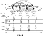
- a PRH propagates synchronization timing information by compensating for propagation delay using round trip time measurements.
- FIG. 4B includes a block diagram 450 and timing graph 452 illustrating timing propagation based on round trip time measurements according to one embodiment.
- the independent PRH1 transmits the first synchronization signal 430 relative to the first timing instance T1 and PRH2 responds with the time of arrival in a physical random access channel (PRACH) 454 or alternative synchronization signal, which allows PRH1 to calculate the round trip time.
- PRACH physical random access channel
- Skilled persons will recognize that PRACH is used by way of example only, and that any signal may be used to communicate time of arrival information to a synchronization source.
- PRH1 uses the time of arrival information received from PRH2 to estimate a round trip time, and then transmits a timing advance (TA) command 456 based on the estimated round trip time.
- PRH2 uses the TA command 456 to pre-compensate for estimated timing bias. The process is repeated for PRH3 and PRH4.
- TA timing advance
- PRH2, PRH3, and PRH4 use respective pre-compensated estimates of the first timing instance T1 as the time relative to which they transmit their respective synchronization signals 432, 434, 436. Similar to the time of arrival approach, however, the synchronization error variances 438, 442, 446 grow during hierarchical timing propagation over consecutive PRH hops. In certain embodiments, even higher synchronization error variance can be expected for timing propagation based on round trip time measurements than that expected based on time of arrival measurements because the number of measurements are doubled by performing time of arrival estimation twice (i.e., at the synchronization source and synchronization acquirer node).
- a dependent PRH may receive synchronization signals from two or more different PRHs. Linearly combining the different synchronization signals may lead to unstable behavior.
- the dependent PRH follows a set of rules to select which of the different synchronization signals to use to derive its own timing.
- the dependent PRH node selects from a plurality of received synchronization signals based on actual propagation conditions.
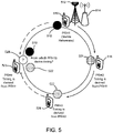
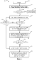
- FIG. 5 is a block diagram illustrating selection of a synchronization source based on timing grade information according to one embodiment.
- a first synchronization source 510 PRH1 provides a stable timing reference.
- a hop count 0 for PRH1.
- the stable timing reference may be based on an internal timer and/or a GNSS signal. If available, the stable timing reference may also be based on a signal received from an eNodeB 512 and/or Wi-Fi access point 514.
- a fourth synchronization source 523 receives both the first synchronization signal 518 from PRH1 and the third synchronization signal 522 from PRH3.
- timing grade information is available to PRH4 for the communication channel between PRH1 and PRH4 and for the communication channel between PRH3 and PRH4.
- the timing grade information may indicate that the received power of the synchronization signal 522 from PRH3 is much greater and/or includes less interference than the received power of the synchronization signal 518 from PRH1.
- PRH4 may elect to derive its timing from PRH3, even though the number of synchronization hops associated with PRH3 is greater than the number of synchronization hops associated with PRH1.
- the hop count can serve as a priority indicator (e.g., synchronization hop count has a high priority for PRH selection as a synchronization source).
- PRH4 can select as a synchronization source the terminal with an earlier time of arrival.
- the timing grade information may be represented by different types of information. For example, metrics may be used such as stability of the oscillator, signal-to-noise ratio, synchronization quality (e.g., error variance), and/or the amount of synchronization propagation hops used to derive the timing from the reference source. Based on the selected design option, the timing grade information may be encoded in multiple ways such as within the synchronization reference sequence, implicitly indicated by the physical position of the synchronization signal transmission, broadcasted over one of the physical channels, or transmitted in any other signal or channel.
- metrics may be used such as stability of the oscillator, signal-to-noise ratio, synchronization quality (e.g., error variance), and/or the amount of synchronization propagation hops used to derive the timing from the reference source.
- the timing grade information may be encoded in multiple ways such as within the synchronization reference sequence, implicitly indicated by the physical position of the synchronization signal transmission, broadcasted over one of the physical channels, or transmitted in any other signal or channel
- the physical structure of the PRH synchronization signal is represented by the primary synchronization signal (PSS) and/or the secondary synchronization signal (SSS), which an eNodeB transmits in the DL direction for cell synchronization, to maximize the reuse of the existing signals defined in LTE technology.
- PSS and SSS signals can be mapped to the center of the corresponding frequency subchannels.
- the physical structure of the PRH synchronization signal may be different than the PSS and/or SSS signal structures and may be specifically designed for D2D operation for out of network coverage and partial network coverage scenarios.
- the physical structure of a synchronization signal encodes the following information to enable synchronous operation for out of network coverage and partial network coverage scenarios: information about the PRH identity (similar to cell-ID to distinguish cell); frequency channel and default spectrum resources owned by a given PRH; and/or timing grade information or type of synchronization source.
- the synchronization signal can be encoded by synchronization of sequence, by position of physical mapping to a spectrum resource (e.g., offset), or by a subset of SSS sequence or PSS/SSS combination.
- a set of available SSS signals may be divided into N subsets, where N is the number of allocated frequency subchannels (see FIG. 1 ) or timeslots.
- Each SSS subset can be further divided into M sub-groups, where M is the maximum number of synchronization hops supported by the system.
- the sequence from the corresponding subset is transmitted by a given PRH to indicate the inheritance (number of hops) in the synchronization signal.
- their synchronization signals are transmitted within same time interval (e.g., subframes of the synchronization frame) to reduce the power consumption of the UEs that are capable to synchronize with multiple PRHs.
- These synchronization signals e.g., PSS/SSS
- PSS/SSS may be transmitted with a low duty cycle that provides an improved or optimal tradeoff between clock drift, synchronization error, and PRH power consumption.
- a staggered transmission of synchronization signals may be advantageous so that PRHs can scan frequency channels and track synchronization signals from each other to support common timing and quasi synchronous operation in the given geographical area.
- a peer-to-peer broadcast and system information physical channel (P2PBSICH), or a physical P2P synchronization channel, is used to carry system information for establishing synchronous operation of the peer terminals.
- P2PBSICH peer-to-peer broadcast and system information physical channel
- the following information may be encoded and carried within the robust P2PBSICH channel: system frame number, a synchronization hop count (e.g., a current hop count or a maximum allowable hop count), and/or configuration of spectrum resources to be used for other D2D functions (e.g., resources used for discovery zone, broadcast zone resources, etc.). Additionally, it may carry information about synchronization source type.
- the peer-to-peer broadcast and system information physical channel is transmitted within resources of the dedicated frequency channel.
- FIG. 6 is a flowchart of an example synchronization method 600 according to one embodiment that enables D2D operation within network coverage as well as for out of network and partial network coverage scenarios.
- the method 600 includes, after powering up 610 a UE, synchronizing 612 PSS and/or SSS signals in the central part of the DL bandwidth.
- the UE scans resources in an attempt to detect the cellular PSS/SSS signals transmitted by an eNodeB. If available, the UE considers the eNodeB to be a primary synchronization source because of the stability of the eNodeB's oscillators and the connection that it provides to the cellular network.
- the UE queries 614 whether synchronization with the eNodeB is acquired and, if yes, the UE attaches to the eNodeB (cellular network).
- the UE scans 618 the UL frequency subchannels used for direct communication for a synchronization signal from a PRH or D2D synchronization source.
- the UE detects a synchronization signal from a PRH or synchronization source, the UE measures 626 synchronization signal quality (e.g., power, signal-to-interference-plus-noise ratio (SINR), synchronization error) in each detected frequency channel, and selectively synchronizes 628 with a frequency channel according to timing grade information taking into account measurements and design criteria (e.g., least congested channel).
- the UE may also query 630 whether it should provide synchronization extension (e.g., become a dependent PRH or synchronization source) to propagate the synchronization signal to other UEs. If yes, the UE starts 624 periodical transmission of its own synchronization signal. In the case of timing propagation, the UE periodically tracks 632 the synchronization reference signal that it receives, if the reference source is available. If the synchronization source becomes unavailable, then the UE scans other synchronization channels for an available reference source.
- synchronization signal quality e.g., power, signal
- FIG. 7 is an example illustration of a mobile device, such as a UE, a mobile station (MS), a mobile wireless device, a mobile communication device, a tablet, a handset, or another type of wireless communication device.
- the mobile device can include one or more antennas configured to communicate with a transmission station, such as a base station (BS), an eNB, a base band unit (BBU), a remote radio head (RRH), a remote radio equipment (RRE), a relay station (RS), a radio equipment (RE), or another type of wireless wide area network (WWAN) access point.
- the mobile device can be configured to communicate using at least one wireless communication standard, including 3GPP LTE, WiMAX, high speed packet access (HSPA), Bluetooth, and Wi-Fi.
- the mobile device can communicate using separate antennas for each wireless communication standard or shared antennas for multiple wireless communication standards.
- the mobile device can communicate in a wireless local area network (WLAN), a wireless personal area network (WPAN), and/or a WWAN.
- FIG. 7 also provides an illustration of a microphone and one or more speakers that can be used for audio input and output from the mobile device.
- the display screen may be a liquid crystal display (LCD) screen or other type of display screen, such as an organic light emitting diode (OLED) display.
- the display screen can be configured as a touch screen.
- the touch screen may use capacitive, resistive, or another type of touch screen technology.
- An application processor and a graphics processor can be coupled to internal memory to provide processing and display capabilities.
- a non-volatile memory port can also be used to provide data input/output options to a user.
- the non-volatile memory port may also be used to expand the memory capabilities of the mobile device.
- a keyboard may be integrated with the mobile device or wirelessly connected to the mobile device to provide additional user input.
- a virtual keyboard may also be provided using the touch screen.
- Various techniques disclosed herein, or certain aspects or portions thereof, may take the form of program code (i.e., instructions) embodied in tangible media, such as floppy diskettes, CD-ROMs, hard drives, a non-transitory computer readable storage medium, or any other machine-readable storage medium wherein, when the program code is loaded into and executed by a machine, such as a computer, the machine becomes an apparatus for practicing the various techniques.
- the computing device may include a processor, a storage medium readable by the processor (including volatile and non-volatile memory and/or storage elements), at least one input device, and at least one output device.
- the volatile and non-volatile memory and/or storage elements may be a RAM, an EPROM, a flash drive, an optical drive, a magnetic hard drive, or another medium for storing electronic data.
- the eNB (or other base station) and UE (or other mobile station) may also include a transceiver component, a counter component, a processing component, and/or a clock component or timer component.
- One or more programs that may implement or utilize the various techniques described herein may use an application programming interface (API), reusable controls, and the like. Such programs may be implemented in a high-level procedural or an object-oriented programming language to communicate with a computer system.
- API application programming interface
- program(s) may be implemented in assembly or machine language, if desired.
- the language may be a compiled or interpreted language, and combined with hardware implementations.
- a component may be implemented as a hardware circuit comprising custom very large scale integration (VLSI) circuits or gate arrays, off-the-shelf semiconductors such as logic chips, transistors, or other discrete components.
- VLSI very large scale integration
- a component may also be implemented in programmable hardware devices such as field programmable gate arrays, programmable array logic, programmable logic devices, or the like.
- Components may also be implemented in software for execution by various types of processors.
- An identified component of executable code may, for instance, comprise one or more physical or logical blocks of computer instructions, which may, for instance, be organized as an object, a procedure, or a function. Nevertheless, the executables of an identified component need not be physically located together, but may comprise disparate instructions stored in different locations that, when joined logically together, comprise the component and achieve the stated purpose for the component.
Description
- The present disclosure relates to direct device-to-device communication and, in particular, to outside network coverage and partial network coverage scenarios using Long Term Evolution (LTE) air interface for interference management and scheduling.
-
-
FIG. 1 is a block diagram illustrating example uplink spectrum resources partitioning for peer-to-peer synchronization according to one embodiment. -
FIGS. 2A, 2B, and 2C are block diagrams illustrating non-overlapped, partially - overlapped, and overlapped scenarios that may result from a synchronization protocol according to certain embodiments.
-
FIGS. 3 A and 3B are block diagrams illustrating extension of a synchronization area according to one embodiment. -
FIG. 4A includes a block diagram and timing graph illustrating timing propagation based on time of arrival measurements according to one embodiment. -
FIG. 4B includes a block diagram and timing graph illustrating timing propagation based on round trip time measurements according to one embodiment. -
FIG. 5 is a block diagram illustrating selection of a synchronization source based on timing grade information according to one embodiment. -
FIG. 6 is a flowchart of an example synchronization method according to one embodiment that enables D2D operation within network coverage as well as for out of network and partial network coverage scenarios. -
FIG. 7 is an example illustration of a mobile device according to certain embodiments. - In XP050697812D1, synchronous operation of two UEs is disclosed. One UE is connected to an eNB and communicates directly with a second UE. Multiple UEs in various synchronization clusters synchronize. Tthe UEs involved are able to elect one of the devices as the synchronization reference.
- In XP050697815, a UE deriving synchronization from an NW (eNB) is disclosed. Further, D2D discovery between UEs is disclosed.
- In XP05069960, D2D communication between UEs is disclosed, including UEs being out of network coverage.
- The invention is defined by the appended claims.
- A detailed description of systems and methods consistent with embodiments of the present disclosure is provided below. The invention is disclosed in sections IV and V.
- In addition, while numerous specific details are set forth in the following description in order to provide a thorough understanding of the embodiments disclosed herein, some embodiments can be practiced without some or all of these details. Moreover, for the purpose of clarity, certain technical material that is known in the related art has not been described in detail in order to avoid unnecessarily obscuring the disclosure.
- Wireless mobile communication technology uses various standards and protocols to transmit data between a base station and a wireless communication device. Wireless communication system standards and protocols can include, for example, the 3rd Generation Partnership Project (3GPP) Long Term Evolution (LTE); the Institute of Electrical and Electronics Engineers (IEEE) 802.16 standard, which is commonly known to industry groups as worldwide interoperability for microwave access (WiMAX); and the IEEE 802.11 standard, which is commonly known to industry groups as Wi-Fi. In 3GPP LTE radio access networks (RANs), the base station can include Evolved Universal Terrestrial Radio Access Network (E-UTRAN) Node Bs (also commonly denoted as evolved Node Bs, enhanced Node Bs, eNodeBs, or eNBs), and/or Radio Network Controllers (RNCs) in an E-UTRAN, which communicate with a wireless communication device, known as user equipment (UE).
- LTE networks include radio access technology and core radio network architecture that provide high data rate, low latency, packet optimization, and improved system capacity and coverage. In LTE networks, an E-UTRAN includes a plurality of eNodeBs and communicates with a plurality of UEs. A downlink (DL) transmission in an LTE network can be defined as a communication from the eNodeB to a UE, and an uplink (UL) transmission can be defined as a communication from the UE to the eNodeB.
- There are various applications and use cases proposed in 3GPP which may involve network initiated or UE initiated communication to or among a group of users and/or devices. In current LTE standard development, device-to-device (D2D) (also referred to herein as "peer-to-peer" or "P2P") communication is one field for enhancement for future releases (e.g., Release 12 and later versions) where UEs are able to communicate directly with other UEs without routing communications via an eNodeB or the core network. D2D has been proposed for local social networks, content sharing, location based marketing, serving advertisements, mobile to mobile applications, public safety, etc. D2D communications are of interest due to their ability to reduce load on a core network or access network, increase data rates due to direct and short communication paths, provide public safety communication paths, and provide other functionality.
- By way of example, public safety demands for direct communication have motivated the study of peer-to-peer communication solutions based on the LTE air-interface. One of the challenging public safety requirements is to enable direct communication for outside of network coverage scenarios. A difference of this scenario from traditional LTE deployment scenarios is that there is no eNodeB available. The eNodeB provides multiple functional roles such as synchronization and radio resource management. LTE technology defines fully synchronous operation between an eNodeB and UEs. A mobile terminal (e.g., UE) synchronizes to the eNodeB synchronization and reference signals. In addition, the UE operation is configured by the eNodeB, and the UE terminal follows eNodeB instructions and commands in terms of spectrum resource management.
- Synchronous operation uses synchronization in absolute time among UE terminals or relative to the terminal providing the reference synchronization signals. Because it is already supported by UE terminals, the inventors of the present application have recognized that the extension of synchronous operation is a useful design choice for out of network coverage and partial network coverage scenarios. However, establishing synchronization for out of coverage scenarios is not a simple technical problem and may suffer from multiple sources of errors that can result in non-accurate synchronization. One of the challenges, for example, is that public safety scenarios assume rather large incident areas where multiple first responder groups may operate simultaneously (e.g., in response to earthquake, forest fire, etc.). In this case, the synchronization may need to be established over a large geographical area using an air interface.
- A solution to establish common synchronization is to use a common reference source for all devices. In particular, Global Navigation Satellite System (GNSS) based solutions, such as the Global Positioning System (GPS), Global Navigation Satellite System (GLONASS), Galileo, or Beidou, may be considered for providing a reliable reference source. However, due to generally poor performance of GNSS devices in indoor environments, as well as for security reasons (GNSS solutions are generally owned by individual countries), such solutions may not always be always appropriate. Therefore, alternative design approaches are needed for the out of coverage and partial network coverage scenarios.
- In certain embodiments disclosed herein, methods are provided for enabling synchronous operation for out of coverage public safety specific scenarios. In particular, a system level solution is provided to reduce collision and synchronization errors among public safety terminals and establish synchronous operation over large geographical areas. It should be understood, however, that the public safety scenarios are provided by way of example only, and that the disclosed embodiments may be used in any number of scenarios, including commercial, government, and private use scenarios.
- Synchronous operation provides for capacity, energy efficiency, and long range communication ability, which are useful for public safety. In dense ad-hoc networks that are typical for the public safety specific use cases, the communication rate and range is often limited by interference from multiple transmission points that are not synchronized to each other. The lack of synchronization creates strong mutual interference to intended receivers. In addition, such asynchronous networks are not power efficient because terminals may need to continuously or frequently monitor the medium in order to receive a signal in which the transmission time is unknown a priori.
- To avoid the mentioned drawbacks, certain embodiments disclosed herein synchronize the operation of public safety terminals involved in (or responding to) a common incident. A synchronization protocol may be used to establish synchronous operation of mobile public safety terminals in proximity areas for out of coverage and partial coverage scenarios. In the synchronization protocol, one or more public safety devices, referred to herein as peer radio heads (PRH) or D2D synchronization sources, play the role of the synchronization reference for the remaining terminals in the surrounding area. These PRH terminals or D2D synchronization sources may facilitate maintaining the synchronous operation in the neighboring geographical areas and provide synchronous or quasi-synchronous operation over large geographical areas.
- The protocol, according to certain embodiments, may also facilitate the collision free communication among multiple public safety groups (broadcast and groupcast) operating close to each other and distributed over large incident areas to perform their public safety missions. The synchronization protocol ensures that neighboring proximity areas operate synchronously by using a local synchronization protocol with hierarchical timing propagation.
- The example public safety use cases assume multiple direct groupcast and/or broadcast transmissions among the public safety terminals serving in a particular incident area. There may be multiple public safety groups that work in nearby or even the same geographical area and that may need to have reliable communication between each other as well as reliable discovery of each other or even members of the other groups.
- To provide concurrent communication among different user groups, certain embodiments use collision avoidance algorithms so that members of different groups can access the medium and not interfere with each other. It may also be useful to provide terminals a low power consumption and a long communication range. Thus, in certain embodiments, the LTE system bandwidth is divided into multiple frequency subchannels (frequency sub-bands), which can be used for data transmission and by default owned (i.e., reserved) by the members of the particular public safety group. In addition or in other embodiments, one or more of the public safety specific devices, referred to as PRHs or D2D synchronization sources, serve as a synchronization reference point that broadcasts synchronization signals in order to establish synchronous operation and provide energy savings for terminals that belong to the particular public safety group(s) served by given PRH(s).
- In the following sections, example embodiments are described with respect to the figures, which form a part hereof, and which show, by way of illustration, specific embodiments or processes in which the embodiments may be practiced. Where possible, the same reference numbers are used throughout the drawings to refer to the same or like components. The following sections describe spectrum partitioning and multiple synchronization subchannels, aggregation and/or concatenation of frequency subchannels (including synchronization areas and extension of synchronization areas), synchronization mechanisms based on hierarchical timing propagation, timing grade information, synchronization signal structure, broadcast channel description, and synchronization procedures.
- Unlike the situation where an eNodeB provides synchronization and reference signals in downlink (DL) carrier resources, certain embodiments disclosed herein define uplink (UL) carrier resources that a UE (e.g., configured as a PRH or synchronization source) uses to transmit synchronization signals to peer UEs for direct communications.
-
FIG. 1 is a block diagram illustrating example UL spectrum resource partitioning for peer-to-peer synchronization according to one embodiment. This example is provided for frequency division multiplexing (FDM) embodiments. However, as discussed below, other embodiments may provide for time division multiplexing (TDM) or combinations of FDM and TDM. As shown inFIG. 1 , a plurality of UL frames 110 includes synchronization (sync) frames 112, 114 at a predetermined sync frame period. The sync frames 112, 114 are each divided into a plurality ofUL subframes 116. According to the illustrated example, eachUL frame 110 has a duration of 10 milliseconds (ms), the start of the sync frames are separated in time by 80 ms (e.g., the sync frame period is 80 ms), and each subframe has a duration of 1 ms. Skilled persons will recognize, however, that other frame durations, sync frame periods, and subframe durations may also be used. - According to the illustrated example, the LTE system bandwidth is divided into N
logical frequency subchannels 118. In other embodiments, the spectrum resources can be divided into time subchannels or time-frequency subchannels. A synchronization signal (sync signal) 120 is included within one of the frequency subchannels. As shown in the example ofFIG. 1 ,frequency subchannel # 3 includes the sync signal 120. In FDM embodiments, eachlogical frequency subchannel 118 is composed from multiple (M) physical resource blocks (PRBs). In TDM embodiments, the resources may be divided into time slots, subframes or frames instead of frequency subchannels. In other embodiments, a combination of both frequency subchannels and time slots or subframes may be used. In certain embodiments, the FDM partitioning of the resources is more advantageous than TDM partitioning because operation of multiple public safety groups within the neighboring areas may happen to be non-synchronized. In the general case illustrated inFIG. 1 , the FDM partitioning may reduce interference (collision) as compared to the TDM alternative in case of asynchronous areas. In addition, the sub-channelization gain can be extracted when the terminal transmits at maximum power in the subset of the overall frequency resources. The term "logical frequency channel" is used here to indicate that actual mapping of logical frequency resources to physical resource elements of the LTE system may be subject to any resource permutation or resource hopping function, although the orthogonality of physical resources is still preserved. - A function of a PRH device or a synchronization source is to establish a local synchronization area within a given radius (determined by transmission range of the synchronization signal 120). The public safety terminals (UEs) that are within synchronization range can receive the synchronization signal 120 from the given PRH or synchronization source and establish a common timing reference so that their subsequent transmissions and/or operations are aligned in time and frequency. Therefore, terminals can achieve synchronization in time and frequency and thus synchronous communication becomes feasible. In certain embodiments, the established synchronization can be used by upper layer protocols for capacity and energy efficient transmission.
- In certain embodiments, the transmission period of the synchronization signal 120 (i.e., the sync frame period) is a tradeoff between clock drift (frequency stability) and power consumption. More accurate (stable) oscillators installed in the public safety devices may require longer sync frame periods. From the physical layer perspective, the sync frame period may be selected to keep the synchronization error within a small part of the cyclic prefix (CP) duration (e.g., 1/8 or 1/4 of CP time) to prevent asynchronous interference. At the same time, small sync frame periods increase the power consumption because the PRHs and other public safety terminals would need to more frequently monitor the transmission of the synchronization signal 120. In order to balance these two factors, the synchronization signal 120 can be transmitted periodically once per L frames.
- The frame where the synchronization signal 120 is transmitted is called a
synchronization frame 112. To be more specific, using LTE terminology, the synchronization signal 120 may be transmitted in the set ofsubframes 116 of thesynchronization frame 112.FIG. 1 shows an example when the synchronization signal 120 is transmitted every 80 ms. (i.e., L = 8 LTE frames). It should be noted that the synchronization procedure described above assumes synchronization at the physical layer so that multiple concurrent transmissions within given geographical area do not cause inter-carrier interference, appearing when transmissions are not time aligned. On the other hand, the synchronization requirement may be relaxed such as to achieve synchronization at the upper layers only, but admit asynchronous transmissions from the physical layer perspective. In the latter case, the synchronization error requirements may be relaxed substantially. - When multiple public safety groups compete for resources, certain embodiments also orthogonalize transmission of the synchronization signal 120 in frequency, in time, or in both frequency and time domains. The orthogonalization in time can facilitate simple synchronization techniques between multiple PRHs (i.e., between multiple synchronization sources). The orthogonalization in frequency can facilitate more reliable transmission and interference management. In case of frequency orthogonalization, the frequency channel for synchronization signal transmission can be either pre-configured or selected by the PRH or synchronization source during the scanning procedure. In embodiments of the latter case, the PRH or synchronization source scans all available frequency channels before establishing its own synchronization in a particular frequency channel. As a result of the scanning procedure, the PRH or synchronization source selects the frequency channel where the received power of a synchronization signal (e.g., from another synchronization source) has a minimum value or where a synchronization signal is not detectable. In other embodiments, the PRH or synchronization source can select the time or time-frequency subchannel when executing a scanning procedure. In these embodiments, the scanning may be simplified since the terminal does not need to scan multiple frequencies. However, if there is not enough time resources, the additional frequency dimension can be used to further improve performance.
- In certain embodiments, other criteria are also used for selection of the synchronization (frequency) channel. According to one embodiment, for example, the PRH or synchronization source may select the frequency subchannel which is least congested from its receiver perspective. Note that once the synchronization channel is selected, the spectrum resources of this logical frequency channel are associated with or owned (i.e., reserved) by given PRH node or synchronization source.
- The division of frequency subchannels enables collision free operation when multiple PRHs or synchronization sources establish synchronization areas in geographically overlapping regions. Depending on the scenario, there may be a plurality of PRHs or synchronization sources detectable in a given area. In this case, the remaining non-occupied resources may be shared between deployed PRHs or synchronization sources. Certain embodiments use non-default frequency subchannels to increase throughput for D2D operation within the given synchronization area and at the same time control interference between devices that belong to different synchronization areas. In certain embodiments, a UE may autonomously select itself (i.e., self-configuration) to act as a PRH or synchronization source based on detection of synchronization signals (and/or lack thereof). For out of network coverage scenarios, for example, an autonomous selection and reselection of mobile synchronization sources may be used. In other embodiments, such as in network coverage or certain partial network coverage scenarios, an eNodeB may assign UEs to serve as PRHs or synchronization sources.
- In certain embodiments, each PRH or synchronization source establishes its own local synchronization area to provide common reference timing for multiple devices (UEs) located within its synchronization range, and thus associated to the PRH or synchronization source. In a simple case, the term "associated" means that UEs (e.g., public safety terminals) follow the synchronization signal transmitted by a given PRH or synchronization source, and use a derived timing based on the synchronization signal for their own operation. In other cases, the term "associated" means that UEs (e.g., public safety terminals) perform an access procedure, and that the PRH or synchronization source assists in radio resource management functions as well.
-
FIGS. 2A, 2B, and 2C are block diagrams illustrating non-overlapped 210, partially overlapped 212, and overlapped 214 scenarios that may result from the described synchronization protocol according to certain embodiments. As shown, afirst synchronization area 216 includes afirst UE 218 configured as (e.g., autonomously selected or self-configured as) a synchronization source (PRH1) to provide a synchronization signal to a first group ofUEs 220, and asecond synchronization area 222 includes asecond UE 224 configured as (e.g., autonomously selected or self-configured as) a synchronization source (PRH2) to provide synchronization signals to a second group ofUEs 226. -
FIG. 2A shows non-overlapped 210synchronization areas first synchronization area 216 and thesecond synchronization area 222 are asynchronous with one another. Further, in the non-overlapped 210 case, there are noUEs -
FIG. 2B shows partially overlapped 212synchronization areas FIG. 2A ). Accordingly, thefirst synchronization area 216 and thesecond synchronization area 222 are asynchronous with one another. InFIG. 2B , however, UEs 220(a) and 226(a) within an overlapped region ofsynchronization areas -
FIG. 2C shows overlapped 214synchronization areas first synchronization area 216 and thesecond synchronization area 222 may become synchronous with each other. In certain embodiments, as discussed below, this is done by selecting one of PRH1 or PRH2 as a common reference source. - When synchronization areas of two PRHs or two synchronization sources are overlapped (as shown in
FIG. 2C ), the PRHs or synchronization sources can establish common timing by selecting one of the PRHs or synchronization sources as a common synchronization source. In this case, after a re-synchronization procedure, the whole extended area (i.e., both synchronization areas) operates synchronously. - In addition, or in other embodiments, a PRH or synchronization source may send a request to one or more of the UEs in its synchronization area to start broadcasting synchronization signals in order to extend the synchronization area. For example,
FIGS. 3A and 3B are block diagrams illustrating extension of asynchronization area 310 according to one embodiment. In this example, thesynchronization area 310 includes aUE 312 configured as (e.g., autonomously selected or self-configured as) a synchronization source (PRH1) to provide a first synchronization signal to a group ofUEs FIG. 3A , however, aUE 318 is located outside of thesynchronization area 310. In other words, theUE 318 is beyond the range of receiving the first synchronization signal from PRH1. - In certain embodiments, the
UE 316 within thesynchronization area 310 is configured to detect theUE 318outside synchronization area 310, and theUE 316 responds by notifying PRH1 of the presence of theUE 318. In other embodiments, theUE 316 may receive a request from theUE 318 to join the group ofUEs UE 316 forwards the request to PRH1. In response, PRH1 sends arequest 320 to theUE 316 to synchronize itself based on the first synchronization signal received on a first frequency subchannel (frequency subchannel #1) or time slot and to start transmission of the synchronization signal in a second frequency subchannel (frequency subchannel #2) or time slot. TheUE 316 responds to the request by transmitting a second synchronization signal in the same synchronization frame as the first synchronization signal received from PRH1. Thus, theUE 316 becomes a D2D synchronization source (PRH2) that extends thesynchronization area 310 to theUE 318, as shown inFIG. 3B . PRH2 derives synchronization (timing) for the second synchronization signal from the first synchronization signal received from PRH1. Accordingly, theUE 318 uses the second synchronization signal received from PRH2 to synchronize with the group ofUEs - To expand the geographical areas of synchronous D2D operation, different synchronization mechanisms can be applied. However, in certain embodiments, the number of hops (i.e., propagation of timing information from one PRH to another) is limited because synchronization timing error accumulates from hop to hop). This may be illustrated in two example embodiments where timing propagation is based on time of arrival measurements or round trip time measurements.
- In the first example embodiment, a PRH propagates synchronization timing information by measuring the time of arrival of a synchronization signal from another node. The estimated time of arrival is used as the timing instance relative to which the PRH transmits its own synchronization signals. For example,
FIG. 4A includes a block diagram 410 andtiming graph 412 illustrating timing propagation based on time of arrival measurements according to one embodiment. InFIG. 4A , afirst UE 414 is configured as (e.g., autonomously selected or self-configured as) a first synchronization source (PRH1) with a range corresponding to afirst synchronization area 416, asecond UE 418 is configured as (e.g., autonomously selected or self-configured as) a second synchronization source (PRH2) with a range corresponding to asecond synchronization area 420, athird UE 422 is configured as (e.g., autonomously selected or self-configured as) a third synchronization source (PRH3) with a range corresponding to athird synchronization area 424, and afourth UE 426 is configured as (e.g., autonomously selected or self-configured as) a fourth synchronization source (PRH4) with a range corresponding to afourth synchronization area 428. - In this example, PRH1 may be referred to as an independent synchronization source because it does not derive synchronization information from another node. PRH2, PRH3, and PRH4 may be referred to as dependent or regional synchronization sources because they each derive synchronization (timing) from another source. For example, PRH1 sends a
first synchronization signal 430 to PRH2, PRH2 sends asecond synchronization signal 432 to PRH3, and PRH3 sends athird synchronization signal 434 to PRH4. That is to say, PRH1 is an independent or overall reference source (top of the hierarchy) that generates frame timing information, PRH2 derives frame timing information from PRH1, PRH3 derives frame timing information from PRH2, and PRH4 derives frame timing information from PRH3. - Referring to the
timing graph 412 ofFIG. 4A , a first timing instance T1 is shown, relative to which PRH1 transmits thefirst synchronization signal 430. PRH2 measures the time of arrival of thefirst synchronization signal 430 at a second timing instance T2. PRH2 uses the measured second timing instance T2 as the time relative to which it transmits itsown synchronization signal 432. Similarly, PRH3 measures the time of arrival of thesynchronization signal 432, which it uses as a third timing instance T3 to which PRH3 transmits itssynchronization signal 434. PRH4 measures receiving thesynchronization signal 434 at a fourth timing instance T4 to which PRH4 transmits itssynchronization signal 436. - A first propagation delay TPD1 is a time period between the first timing instance T1 and the second timing instance T2. Due to an amount of unknown delay within the first propagation delay TPD1, PRH2's timing estimate based on the time of arrival of the
synchronization signal 430 includes asynchronization error variance 438. Similarly, a second propagation delay TPD2 is a time period between the second timing instance T2 and the third timing instance T3, which contributes to a secondsynchronization error variance 442. Finally, a third propagation delay TPD3 is a time period between the third timing instance T3 and the fourth timing instance T4, which contributes to a thirdsynchronization error variance 446. - The example embodiment shown in
FIG. 4A is relatively simple (e.g., it does not include propagation error compensation discussed with respect toFIG. 4B ) and can be applied in practice for synchronous operation in neighboring areas. For example, the embodiment ofFIG. 4A provides synchronous operation betweenarea 416 andarea 420, synchronous operation betweenarea 420 andarea 424, or synchronous operation betweenarea 424 andarea 428. The example embodiment may also provide quasi-synchronous operation betweenarea 416 andarea 424, which do not substantially physically overlap with one another (if at all). However the example method shown inFIG. 4A may suffer from biased timing due to the propagation delays TPD1, TPD2, and TPD3 between PRH1, PRH2, and PRH3, respectively, so that synchronization error grows with the amount of timing inheritance. Due to multiple timing estimates, thesynchronization error variances area 428 may become asynchronous with thearea 416 of the independent or overall synchronization source PRH1. It is noted that propagation delay for proximate communication may be neglected in certain embodiments since for practical communication ranges, e.g., up to 300 meters, the error due to propagation delay can be absorbed by the duration of the cyclic prefix. - In the second example embodiment, a PRH propagates synchronization timing information by compensating for propagation delay using round trip time measurements. For example,
FIG. 4B includes a block diagram 450 andtiming graph 452 illustrating timing propagation based on round trip time measurements according to one embodiment. In this example, the independent PRH1 transmits thefirst synchronization signal 430 relative to the first timing instance T1 and PRH2 responds with the time of arrival in a physical random access channel (PRACH) 454 or alternative synchronization signal, which allows PRH1 to calculate the round trip time. Skilled persons will recognize that PRACH is used by way of example only, and that any signal may be used to communicate time of arrival information to a synchronization source. PRH1 uses the time of arrival information received from PRH2 to estimate a round trip time, and then transmits a timing advance (TA) command 456 based on the estimated round trip time. PRH2 uses the TA command 456 to pre-compensate for estimated timing bias. The process is repeated for PRH3 and PRH4. - Thus, as shown in the
timing graph 452 ofFIG. 4B , PRH2, PRH3, and PRH4 use respective pre-compensated estimates of the first timing instance T1 as the time relative to which they transmit their respective synchronization signals 432, 434, 436. Similar to the time of arrival approach, however, thesynchronization error variances - As discussed in the previous section, when PRHs hierarchically derive (inherit) synchronization from each other, the synchronization timing error is increased. Therefore, after several hops the synchronization acquirer may become non-synchronous with the independent reference source. A dependent PRH may receive synchronization signals from two or more different PRHs. Linearly combining the different synchronization signals may lead to unstable behavior. Thus, in certain embodiments, the dependent PRH follows a set of rules to select which of the different synchronization signals to use to derive its own timing.
- In one embodiment, a dependent PRH selects the synchronization signal associated with the lower number of hop count. For example, an independent PRH node prioritizes the derivation of the timing information from the independent PRH (which communicates that its synchronization hop count = 0), instead of from a dependent PRH node (which communicates that its synchronization hop count > 0) that has derived synchronization from another PRH. If a synchronization signal from the independent PRH is not available, then priority is given to the PRH that derives its timing with the lowest number of hops because it will likely have a lower synchronization error. Such prioritization may be useful, for example, if measurement errors for each hop are expected to be of the same order and to accumulate from hop to hop.
- In addition, or in other embodiments, the dependent PRH node selects from a plurality of received synchronization signals based on actual propagation conditions. For example,
FIG. 5 is a block diagram illustrating selection of a synchronization source based on timing grade information according to one embodiment. In this example, a first synchronization source 510 (PRH1) provides a stable timing reference. A hop count = 0 for PRH1. The stable timing reference may be based on an internal timer and/or a GNSS signal. If available, the stable timing reference may also be based on a signal received from aneNodeB 512 and/or Wi-Fi access point 514. A second synchronization source 516 (PRH2) derives its timing from afirst synchronization signal 518 transmitted by PRH1. The hop count = 1 for PRH2. A third synchronization source 520 (PRH3) derives its timing from asecond synchronization signal 521 transmitted by PRH2. The hop count = 2 for PRH3. - In the example shown in
FIG. 5 , a fourth synchronization source 523 (PRH4) receives both thefirst synchronization signal 518 from PRH1 and thethird synchronization signal 522 from PRH3. PRH4 selects 524 whether to synchronize to PRH1 (hop count = 0) or PRH3 (hop count = 2) as the reference source. To assist in the selection of the reference source, timing grade information is available to PRH4 for the communication channel between PRH1 and PRH4 and for the communication channel between PRH3 and PRH4. For example, the timing grade information may indicate that the received power of thesynchronization signal 522 from PRH3 is much greater and/or includes less interference than the received power of thesynchronization signal 518 from PRH1. Based on this determination, PRH4 may elect to derive its timing from PRH3, even though the number of synchronization hops associated with PRH3 is greater than the number of synchronization hops associated with PRH1. In other cases, the hop count can serve as a priority indicator (e.g., synchronization hop count has a high priority for PRH selection as a synchronization source). Alternatively, PRH4 can select as a synchronization source the terminal with an earlier time of arrival. - Depending on the implementation, the timing grade information may be represented by different types of information. For example, metrics may be used such as stability of the oscillator, signal-to-noise ratio, synchronization quality (e.g., error variance), and/or the amount of synchronization propagation hops used to derive the timing from the reference source. Based on the selected design option, the timing grade information may be encoded in multiple ways such as within the synchronization reference sequence, implicitly indicated by the physical position of the synchronization signal transmission, broadcasted over one of the physical channels, or transmitted in any other signal or channel.
- In certain embodiments, the physical structure of the PRH synchronization signal is represented by the primary synchronization signal (PSS) and/or the secondary synchronization signal (SSS), which an eNodeB transmits in the DL direction for cell synchronization, to maximize the reuse of the existing signals defined in LTE technology. The PSS and SSS signals can be mapped to the center of the corresponding frequency subchannels. In other embodiments, however, the physical structure of the PRH synchronization signal may be different than the PSS and/or SSS signal structures and may be specifically designed for D2D operation for out of network coverage and partial network coverage scenarios.
- In certain embodiments, the physical structure of a synchronization signal encodes the following information to enable synchronous operation for out of network coverage and partial network coverage scenarios: information about the PRH identity (similar to cell-ID to distinguish cell); frequency channel and default spectrum resources owned by a given PRH; and/or timing grade information or type of synchronization source.
- For the case when timing grade information is represented by the amount of synchronization timing hops, the synchronization signal can be encoded by synchronization of sequence, by position of physical mapping to a spectrum resource (e.g., offset), or by a subset of SSS sequence or PSS/SSS combination. For example, a set of available SSS signals may be divided into N subsets, where N is the number of allocated frequency subchannels (see
FIG. 1 ) or timeslots. Each SSS subset can be further divided into M sub-groups, where M is the maximum number of synchronization hops supported by the system. Depending on the number of synchronization hops, according to such an embodiment, the sequence from the corresponding subset is transmitted by a given PRH to indicate the inheritance (number of hops) in the synchronization signal. - For PRHs synchronized with each other, according to certain embodiments, their synchronization signals are transmitted within same time interval (e.g., subframes of the synchronization frame) to reduce the power consumption of the UEs that are capable to synchronize with multiple PRHs. These synchronization signals (e.g., PSS/SSS) may be transmitted with a low duty cycle that provides an improved or optimal tradeoff between clock drift, synchronization error, and PRH power consumption. In particular, a staggered transmission of synchronization signals (e.g., PSS/SSS) may be advantageous so that PRHs can scan frequency channels and track synchronization signals from each other to support common timing and quasi synchronous operation in the given geographical area.
- In addition, or in other embodiments, a peer-to-peer broadcast and system information physical channel (P2PBSICH), or a physical P2P synchronization channel, is used to carry system information for establishing synchronous operation of the peer terminals. For example, the following information may be encoded and carried within the robust P2PBSICH channel: system frame number, a synchronization hop count (e.g., a current hop count or a maximum allowable hop count), and/or configuration of spectrum resources to be used for other D2D functions (e.g., resources used for discovery zone, broadcast zone resources, etc.). Additionally, it may carry information about synchronization source type.
- The peer-to-peer broadcast and system information physical channel, according to one embodiment, is transmitted within resources of the dedicated frequency channel.
-
FIG. 6 is a flowchart of anexample synchronization method 600 according to one embodiment that enables D2D operation within network coverage as well as for out of network and partial network coverage scenarios. Themethod 600 includes, after powering up 610 a UE, synchronizing 612 PSS and/or SSS signals in the central part of the DL bandwidth. In other words, the UE scans resources in an attempt to detect the cellular PSS/SSS signals transmitted by an eNodeB. If available, the UE considers the eNodeB to be a primary synchronization source because of the stability of the eNodeB's oscillators and the connection that it provides to the cellular network. Thus, the UE queries 614 whether synchronization with the eNodeB is acquired and, if yes, the UE attaches to the eNodeB (cellular network). - If, however, synchronization with the eNodeB is not acquired, the UE scans 618 the UL frequency subchannels used for direct communication for a synchronization signal from a PRH or D2D synchronization source. The UE queries 620 whether such a synchronization signal is detected. If the UE does not detect a synchronization signal, the UE queries 622 whether it should establish a synchronization area for a group of UEs by starting 624 periodical transmission of its own synchronization signal. The determination of whether or not the UE should establish a synchronization area in the absence of other synchronization signals may be based on user input and/or pre-authorization to act as a PRH for the group of UEs. If the UE determines that it should not establish a synchronization area, the UE continues scanning 618 frequency subchannels for a synchronization signal from a PRH or synchronization source.
- If the UE detects a synchronization signal from a PRH or synchronization source, the UE measures 626 synchronization signal quality (e.g., power, signal-to-interference-plus-noise ratio (SINR), synchronization error) in each detected frequency channel, and selectively synchronizes 628 with a frequency channel according to timing grade information taking into account measurements and design criteria (e.g., least congested channel). The UE may also query 630 whether it should provide synchronization extension (e.g., become a dependent PRH or synchronization source) to propagate the synchronization signal to other UEs. If yes, the UE starts 624 periodical transmission of its own synchronization signal. In the case of timing propagation, the UE periodically tracks 632 the synchronization reference signal that it receives, if the reference source is available. If the synchronization source becomes unavailable, then the UE scans other synchronization channels for an available reference source.
-
FIG. 7 is an example illustration of a mobile device, such as a UE, a mobile station (MS), a mobile wireless device, a mobile communication device, a tablet, a handset, or another type of wireless communication device. The mobile device can include one or more antennas configured to communicate with a transmission station, such as a base station (BS), an eNB, a base band unit (BBU), a remote radio head (RRH), a remote radio equipment (RRE), a relay station (RS), a radio equipment (RE), or another type of wireless wide area network (WWAN) access point. The mobile device can be configured to communicate using at least one wireless communication standard, including 3GPP LTE, WiMAX, high speed packet access (HSPA), Bluetooth, and Wi-Fi. The mobile device can communicate using separate antennas for each wireless communication standard or shared antennas for multiple wireless communication standards. The mobile device can communicate in a wireless local area network (WLAN), a wireless personal area network (WPAN), and/or a WWAN. -
FIG. 7 also provides an illustration of a microphone and one or more speakers that can be used for audio input and output from the mobile device. The display screen may be a liquid crystal display (LCD) screen or other type of display screen, such as an organic light emitting diode (OLED) display. The display screen can be configured as a touch screen. The touch screen may use capacitive, resistive, or another type of touch screen technology. An application processor and a graphics processor can be coupled to internal memory to provide processing and display capabilities. A non-volatile memory port can also be used to provide data input/output options to a user. The non-volatile memory port may also be used to expand the memory capabilities of the mobile device. A keyboard may be integrated with the mobile device or wirelessly connected to the mobile device to provide additional user input. A virtual keyboard may also be provided using the touch screen. - Various techniques disclosed herein, or certain aspects or portions thereof, may take the form of program code (i.e., instructions) embodied in tangible media, such as floppy diskettes, CD-ROMs, hard drives, a non-transitory computer readable storage medium, or any other machine-readable storage medium wherein, when the program code is loaded into and executed by a machine, such as a computer, the machine becomes an apparatus for practicing the various techniques. In the case of program code execution on programmable computers, the computing device may include a processor, a storage medium readable by the processor (including volatile and non-volatile memory and/or storage elements), at least one input device, and at least one output device. The volatile and non-volatile memory and/or storage elements may be a RAM, an EPROM, a flash drive, an optical drive, a magnetic hard drive, or another medium for storing electronic data. The eNB (or other base station) and UE (or other mobile station) may also include a transceiver component, a counter component, a processing component, and/or a clock component or timer component. One or more programs that may implement or utilize the various techniques described herein may use an application programming interface (API), reusable controls, and the like. Such programs may be implemented in a high-level procedural or an object-oriented programming language to communicate with a computer system.
- However, the program(s) may be implemented in assembly or machine language, if desired. In any case, the language may be a compiled or interpreted language, and combined with hardware implementations.
- It should be understood that many of the functional units described in this specification may be implemented as one or more components, which is a term used to more particularly emphasize their implementation independence. For example, a component may be implemented as a hardware circuit comprising custom very large scale integration (VLSI) circuits or gate arrays, off-the-shelf semiconductors such as logic chips, transistors, or other discrete components. A component may also be implemented in programmable hardware devices such as field programmable gate arrays, programmable array logic, programmable logic devices, or the like.
- Components may also be implemented in software for execution by various types of processors. An identified component of executable code may, for instance, comprise one or more physical or logical blocks of computer instructions, which may, for instance, be organized as an object, a procedure, or a function. Nevertheless, the executables of an identified component need not be physically located together, but may comprise disparate instructions stored in different locations that, when joined logically together, comprise the component and achieve the stated purpose for the component.
Claims (12)
- User equipment, UE, comprising processing circuitry configured to:communicate with a wireless cellular network, determine that synchronization with and attachment to an evolved Node B, eNodeB, of the wireless cellular network is not current available;in response to the determination, scan for and detect a plurality of synchronization signals from corresponding peer radio heads providing a synchronization reference for terminals;measure a signal quality for each of the plurality of synchronization signals;select a first synchronization signal of the plurality of synchronization signals based at least in part on the measured signal quality; andsynchronize a local time source with the selected first synchronization signal;characterized in that selecting the first synchronization signal further comprises:
determine a synchronization hop count for each detected synchronization signal; determine a received power for each detected synchronization signal; andselecting the first synchronization signal based at least in part on the synchronization hop count and the received power,wherein a hop count greater than zero indicates that the corresponding synchronization signal was derived from another synchronization signal. - The UE of claim 1, wherein the processing circuitry is further configured to:communicate with a first group of UEs based on synchronization with the first synchronization signal;determine to extend, to a second group of UEs, the synchronization with the first synchronization signal;in response to the determination, periodically transmit a second synchronization signal to the second group of UEs, the second synchronization signal comprises synchronization information derived from the synchronized of the local timing source with the selected first synchronization signal.
- The UE of claim 1, wherein the processing circuitry is further configured to:communicate with a first group of UEs based on synchronization with the first synchronization signal;determine to extend, to a second group of UEs, the synchronization with the first synchronization signal;in response to the determination, periodically transmit a second synchronization signal to the second group of UEs, the second synchronization signal comprises synchronization information derived from the synchronized of the local timing source with the selected first synchronization signal.
- The UE of claim 1, wherein the processing circuitry is further configured to:detect a subsequent availability of the eNodeB; andin response to the detected subsequent availability, cease synchronization with the first synchronization signal and attaching to the eNodeB.
- A method for synchronization of user equipment, UE, configured to communicate with a wireless cellular network, the method comprising:determining that synchronization with and attachment to an evolved Node B, eNodeB,of the wireless cellular network is not currently available;in response to the determination, scanning for and detecting a plurality of synchronization signals from corresponding peer radio heads providing a synchronization reference for terminals;measuring a signal quality for each of the plurality of synchronization signals;selecting a first synchronization signal of the plurality of synchronization signals based at least in part on the measured signal quality; andsynchronizing a local timing source with the selected first synchronization signal;characterized in that selecting the first synchronization signal further comprises:determining a synchronization hop count for each detected synchronization signal;determining a received power for each detected synchronization signal and selecting the first synchronization signal based at least in part on the synchronization hop count and the received power,wherein a hop count greater than zero indicated that the corresponding synchronization signal was derived from another synchronization signal.
- The method of claim 5, further comprising:communicating with a first group of UEs based on synchronization with the first synchronization signal;determining to extend, to a second group of UEs, the synchronization with the first synchronization signal;in response to the determination, periodically transmitting a second synchronization signal to the second group of UEs, the second synchronization signal comprising synchronization information derived from the synchronizing of the local timing source with the selected first synchronization signal.
- The method of claim 6, wherein determining to extend the synchronization with the first synchronization signal to the second group of UEs comprises one or more triggers selected from a group comprising detecting a presence of the second group of UEs, receiving a request for synchronization from at least one UE in the second group of UEs, and receiving a request or synchronization signal from a peer radio head corresponding to the first synchronization signal.
- The method of claim 5, further comprising:detecting a subsequent availability of the eNodeB; andin response to the detected subsequent availability, ceasing synchronization with the first synchronization signal and attaching to the eNodeB.
- The method of claim 5, wherein determining that synchronization with and attachment to the eNodeB is not currently available comprises:scanning downlink, DL, resources in an attempt to detect a cellular primary synchronization signal,PSS, and secondary synchronization signal, SSS, transmitted by the eNodeB; anddetermining that the PSS and SSS signals are not available from the eNodeB.
- The method of claim 5, wherein scanning for and detecting the plurality of synchronization signals comprises: scanning uplink, UL, frequency subchannels over multiple subframes for the plurality of synchronization signals.
- The method of claim 5, wherein measuring the signal quality comprises measuring, for each detected synchronization signal, one or more parameter selected from a group comprising signal power, signal-to-interference-plus-noise ratio, SINR, a synchronization error, and a standard deviation of synchronization error.
- Machine-readable storage including machine-readable instructions, that when executed by a user equipment UE, cause said UE to carry out the steps of a method as claimed in any preceding claim.
Priority Applications (1)
| Application Number | Priority Date | Filing Date | Title |
|---|---|---|---|
| EP17196767.2A EP3301987B1 (en) | 2013-07-08 | 2014-06-30 | Synchronizing peer-to-peer operation for outside network coverage and partial network coverage using lte air interface |
Applications Claiming Priority (3)
| Application Number | Priority Date | Filing Date | Title |
|---|---|---|---|
| US201361843826P | 2013-07-08 | 2013-07-08 | |
| US14/226,592 US9379856B2 (en) | 2013-07-08 | 2014-03-26 | Synchronizing peer-to-peer operation for outside network coverage and partial network coverage using LTE air interface |
| PCT/US2014/044863 WO2015006082A1 (en) | 2013-07-08 | 2014-06-30 | Synchronizing peer-to-peer operation for outside network coverage and partial network coverage using lte air interface |
Related Child Applications (2)
| Application Number | Title | Priority Date | Filing Date |
|---|---|---|---|
| EP17196767.2A Division EP3301987B1 (en) | 2013-07-08 | 2014-06-30 | Synchronizing peer-to-peer operation for outside network coverage and partial network coverage using lte air interface |
| EP17196767.2A Division-Into EP3301987B1 (en) | 2013-07-08 | 2014-06-30 | Synchronizing peer-to-peer operation for outside network coverage and partial network coverage using lte air interface |
Publications (3)
| Publication Number | Publication Date |
|---|---|
| EP3020237A1 EP3020237A1 (en) | 2016-05-18 |
| EP3020237A4 EP3020237A4 (en) | 2017-01-11 |
| EP3020237B1 true EP3020237B1 (en) | 2022-08-24 |
Family
ID=52132763
Family Applications (8)
| Application Number | Title | Priority Date | Filing Date |
|---|---|---|---|
| EP14822395.1A Active EP3020237B1 (en) | 2013-07-08 | 2014-06-30 | Synchronizing peer-to-peer operation for outside network coverage and partial network coverage using lte air interface |
| EP17196767.2A Active EP3301987B1 (en) | 2013-07-08 | 2014-06-30 | Synchronizing peer-to-peer operation for outside network coverage and partial network coverage using lte air interface |
| EP14823532.8A Active EP3020170B1 (en) | 2013-07-08 | 2014-07-02 | Internet protocol interface selection for routing data traffic |
| EP14823752.2A Active EP3020154B1 (en) | 2013-07-08 | 2014-07-07 | Demodulation reference signals (dmrs) for side information for interference cancellation |
| EP14822483.5A Ceased EP3020150A4 (en) | 2013-07-08 | 2014-07-07 | Coordinated interference mitigation and cancelation |
| EP14822925.5A Active EP3020149B1 (en) | 2013-07-08 | 2014-07-08 | Enhanced node b and methods for network assisted interference cancellation with reduced signaling |
| EP14823369.5A Active EP3020228B1 (en) | 2013-07-08 | 2014-07-08 | Energy-efficient device discovery techniques |
| EP16169847.7A Active EP3094147B1 (en) | 2013-07-08 | 2014-07-08 | Enhanced node b and methods for network assisted interference cancellation with reduced signaling |
Family Applications After (7)
| Application Number | Title | Priority Date | Filing Date |
|---|---|---|---|
| EP17196767.2A Active EP3301987B1 (en) | 2013-07-08 | 2014-06-30 | Synchronizing peer-to-peer operation for outside network coverage and partial network coverage using lte air interface |
| EP14823532.8A Active EP3020170B1 (en) | 2013-07-08 | 2014-07-02 | Internet protocol interface selection for routing data traffic |
| EP14823752.2A Active EP3020154B1 (en) | 2013-07-08 | 2014-07-07 | Demodulation reference signals (dmrs) for side information for interference cancellation |
| EP14822483.5A Ceased EP3020150A4 (en) | 2013-07-08 | 2014-07-07 | Coordinated interference mitigation and cancelation |
| EP14822925.5A Active EP3020149B1 (en) | 2013-07-08 | 2014-07-08 | Enhanced node b and methods for network assisted interference cancellation with reduced signaling |
| EP14823369.5A Active EP3020228B1 (en) | 2013-07-08 | 2014-07-08 | Energy-efficient device discovery techniques |
| EP16169847.7A Active EP3094147B1 (en) | 2013-07-08 | 2014-07-08 | Enhanced node b and methods for network assisted interference cancellation with reduced signaling |
Country Status (10)
| Country | Link |
|---|---|
| US (13) | US9479298B2 (en) |
| EP (8) | EP3020237B1 (en) |
| JP (2) | JP6144827B2 (en) |
| KR (2) | KR101845053B1 (en) |
| CN (8) | CN105474716B (en) |
| ES (1) | ES2720583T3 (en) |
| HK (6) | HK1220070A1 (en) |
| HU (1) | HUE043225T2 (en) |
| TW (2) | TWI640185B (en) |
| WO (6) | WO2015006082A1 (en) |
Families Citing this family (169)
| Publication number | Priority date | Publication date | Assignee | Title |
|---|---|---|---|---|
| US10818119B2 (en) | 2009-02-10 | 2020-10-27 | Yikes Llc | Radio frequency antenna and system for presence sensing and monitoring |
| US10416276B2 (en) | 2010-11-12 | 2019-09-17 | Position Imaging, Inc. | Position tracking system and method using radio signals and inertial sensing |
| US11175375B2 (en) | 2010-11-12 | 2021-11-16 | Position Imaging, Inc. | Position tracking system and method using radio signals and inertial sensing |
| WO2013071302A1 (en) | 2011-11-10 | 2013-05-16 | Guohua Min | Systems and methods of wireless position tracking |
| WO2013077684A1 (en) * | 2011-11-24 | 2013-05-30 | 엘지전자 주식회사 | Method for performing device-to-device communication in wireless access system and apparatus for same |
| US9019924B2 (en) * | 2012-04-04 | 2015-04-28 | Samsung Electronics Co., Ltd. | High-order multiple-user multiple-input multiple-output operation for wireless communication systems |
| US9560592B2 (en) | 2012-04-27 | 2017-01-31 | Qualcomm Incorporated | Method and apparatus for signaling in dense network operations |
| US10269182B2 (en) | 2012-06-14 | 2019-04-23 | Position Imaging, Inc. | RF tracking with active sensory feedback |
| US9782669B1 (en) | 2012-06-14 | 2017-10-10 | Position Imaging, Inc. | RF tracking with active sensory feedback |
| US9519344B1 (en) | 2012-08-14 | 2016-12-13 | Position Imaging, Inc. | User input system for immersive interaction |
| US10180490B1 (en) | 2012-08-24 | 2019-01-15 | Position Imaging, Inc. | Radio frequency communication system |
| WO2014093961A1 (en) | 2012-12-15 | 2014-06-19 | Position Imaging, Inc | Cycling reference multiplexing receiver system |
| KR20150105332A (en) * | 2012-12-21 | 2015-09-16 | 엘지전자 주식회사 | Method and apparatus for device-to-device communication in wireless communication system |
| US10856108B2 (en) | 2013-01-18 | 2020-12-01 | Position Imaging, Inc. | System and method of locating a radio frequency (RF) tracking device using a calibration routine |
| US9482741B1 (en) | 2013-01-18 | 2016-11-01 | Position Imaging, Inc. | System and method of locating a radio frequency (RF) tracking device using a calibration routine |
| US9521637B2 (en) * | 2013-02-14 | 2016-12-13 | Blackberry Limited | Small cell demodulation reference signal and initial synchronization |
| EP2981001B1 (en) | 2013-03-27 | 2020-01-01 | LG Electronics Inc. | Method for canceling interference in wireless communication system and apparatus therefor |
| US9654242B2 (en) * | 2013-04-18 | 2017-05-16 | Telefonaktiebolaget Lm Ericsson (Publ) | Node and method for selecting synchronization source |
| CN110248338B (en) | 2013-05-10 | 2021-12-14 | 华为技术有限公司 | System and method for controlling out-of-network device-to-device communication |
| WO2015002369A1 (en) * | 2013-07-03 | 2015-01-08 | 엘지전자 주식회사 | Method of selecting access |
| US9479298B2 (en) | 2013-07-08 | 2016-10-25 | Intel IP Corporation | Demodulation reference signals (DMRS)for side information for interference cancellation |
| KR102151021B1 (en) * | 2013-08-08 | 2020-09-02 | 삼성전자주식회사 | Method and apparatus for synchronizing frame number among device-to-device communication enabled user equipment |
| US9854506B2 (en) * | 2013-08-08 | 2017-12-26 | Qualcomm Incorporated | Timing synchronization for device-to-device discovery for asynchronous LTE deployments |
| WO2015026111A1 (en) * | 2013-08-18 | 2015-02-26 | 엘지전자 주식회사 | Repeater operation method and apparatus in wireless communication system |
| US20150063301A1 (en) * | 2013-09-04 | 2015-03-05 | Qualcomm Incorporated | Operator controlled apn routing mapping |
| US9307510B2 (en) * | 2013-09-05 | 2016-04-05 | Qualcomm Incorporated | Resource allocation for distributed device-to-device synchronization |
| US10212676B2 (en) * | 2013-09-27 | 2019-02-19 | Lg Electronics Inc. | Method for transmitting synchronisation reference signal for device-to-device (D2D) communication in wireless communication system and apparatus therefor |
| US10334474B2 (en) * | 2013-10-04 | 2019-06-25 | Lg Electronics Inc. | Method for cancelling interference in wireless communication system and device therefor |
| US10634761B2 (en) | 2013-12-13 | 2020-04-28 | Position Imaging, Inc. | Tracking system with mobile reader |
| EP3085173B1 (en) * | 2013-12-20 | 2018-08-15 | Kyocera Corporation | Coverage transition indicator for device-to-device communication |
| US20150189667A1 (en) * | 2013-12-27 | 2015-07-02 | Lg Electronics Inc. | Method and apparatus for performing interference cancellation |
| US9497728B2 (en) | 2014-01-17 | 2016-11-15 | Position Imaging, Inc. | Wireless relay station for radio frequency-based tracking system |
| WO2015115974A1 (en) * | 2014-01-31 | 2015-08-06 | Telefonaktiebolaget L M Ericsson (Publ) | Monitoring synchronization signals in device-to-device communication |
| US10200819B2 (en) | 2014-02-06 | 2019-02-05 | Position Imaging, Inc. | Virtual reality and augmented reality functionality for mobile devices |
| US9577778B2 (en) * | 2014-02-24 | 2017-02-21 | Intel Corporation | Interference reduction using hybrid signaling |
| CN105594259B (en) * | 2014-03-14 | 2019-02-01 | Lg电子株式会社 | For selecting network and executing method and user equipment that business routes |
| CN105940745B (en) * | 2014-03-20 | 2019-08-27 | 夏普株式会社 | Terminal installation, base station apparatus and integrated circuit |
| US9596668B2 (en) | 2014-04-14 | 2017-03-14 | Innovative Technology Lab Co., Ltd. | Method and apparatus for transmitting synchronization signal for device to device communication in wireless communication system |
| WO2015160042A1 (en) | 2014-04-14 | 2015-10-22 | 주식회사 아이티엘 | Method and apparatus for transmitting synchronization signal for direct device to device communication in wireless communication system |
| US10117200B2 (en) * | 2014-04-22 | 2018-10-30 | Lg Electronics Inc. | Method and apparatus for acquiring synchronization for device to device terminal in wireless communication system |
| CN105101387B (en) * | 2014-05-06 | 2019-04-02 | 电信科学技术研究院 | A kind of synchronization processing method and user equipment |
| KR102216830B1 (en) * | 2014-05-09 | 2021-02-18 | 선 페이턴트 트러스트 | Device to device synchronization source selection |
| US10368261B2 (en) * | 2014-05-09 | 2019-07-30 | Samsung Electronics Co., Ltd. | Synchronization method and apparatus for D2D communication |
| CN106464407B (en) * | 2014-05-16 | 2018-12-28 | Lg 电子株式会社 | The method and apparatus for interfering and receiving signal is offset in a wireless communication system |
| US9929756B2 (en) * | 2014-05-16 | 2018-03-27 | Lg Electronics Inc. | Method and apparatus for cancelling interference and receiving signal in wireless communication system |
| WO2015194859A1 (en) * | 2014-06-17 | 2015-12-23 | 엘지전자 주식회사 | Method for receiving synchronizing signals for direct communication between terminals in wireless communication system, and device for same |
| US9603080B2 (en) * | 2014-06-25 | 2017-03-21 | Alcatel-Lucent Usa Inc. | Network assisted ANDSF policy updating |
| US9439147B2 (en) * | 2014-06-30 | 2016-09-06 | Intel IP Corporation | Mechanisms of reducing power consumption for NAN devices |
| CN105281885B (en) * | 2014-07-25 | 2021-04-16 | 中兴通讯股份有限公司 | Time synchronization method and device for network equipment and time synchronization server |
| EP3177084B1 (en) * | 2014-07-29 | 2019-05-01 | Sharp Kabushiki Kaisha | Terminal device, base station device, communications method and integrated circuit |
| EP3179788B1 (en) * | 2014-08-05 | 2019-09-04 | Nec Corporation | Communication apparatus, communication system, control method, and nontemporary computer readable medium on which communication program has been stored |
| CN106664703B (en) | 2014-08-07 | 2022-07-19 | 英特尔公司 | Resource allocation device and medium for D2D synchronous signal transmission |
| EP3200367B1 (en) * | 2014-09-24 | 2021-03-10 | LG Electronics Inc. | Method for transmitting d2d signal and terminal therefor |
| US9992657B2 (en) * | 2014-09-24 | 2018-06-05 | Alcatel Lucent | Relay of charging information for proximity services |
| EP3198812B1 (en) * | 2014-09-25 | 2018-08-15 | Telefonaktiebolaget LM Ericsson (publ) | Congestion mitigation by offloading to non-3gpp networks |
| US9578653B2 (en) | 2014-09-26 | 2017-02-21 | Intel IP Corporation | Network assisted parameter estimation in the presence of inter-cell interference |
| EP3198980B1 (en) * | 2014-09-26 | 2018-06-27 | Telefonaktiebolaget LM Ericsson (publ) | Method, communication device and computer program for enabling device-to-device (d2d) communication for an out-of-network-coverage communication device |
| US20160100400A1 (en) * | 2014-10-03 | 2016-04-07 | Qualcomm Incorporated | Beacon based time division multiplexing synchronization for multiple radio access technology coexistence |
| US10555314B2 (en) * | 2014-10-07 | 2020-02-04 | Hfi Innovation Inc. | Signaling of network-assisted intra-cell interference cancellation and suppression |
| US9888463B2 (en) * | 2014-10-31 | 2018-02-06 | Alcatel Lucent | Interference cancellation and suppression for multi-user multiple-in/multiple out (MIMO) communication |
| US9807713B2 (en) * | 2014-11-14 | 2017-10-31 | Telefonaktiebolaget Lm Ericsson (Publ) | Synchronization in communications networks |
| CN106211027B (en) * | 2014-12-25 | 2021-06-18 | 北京三星通信技术研究有限公司 | Method and equipment for realizing time-frequency synchronization of D2D terminal |
| CN105846976A (en) * | 2015-01-15 | 2016-08-10 | 株式会社Ntt都科摩 | Multi-user multiple-input multiple-output transmission method and base station in wireless communication system |
| CN105992257B (en) * | 2015-01-28 | 2021-01-22 | 中兴通讯股份有限公司 | Public safety communication implementation method and device |
| WO2016130310A1 (en) * | 2015-02-11 | 2016-08-18 | Commscope Technologies Llc | Channel identification in a mimo telecommunication system |
| US10324474B2 (en) | 2015-02-13 | 2019-06-18 | Position Imaging, Inc. | Spatial diversity for relative position tracking |
| US10642560B2 (en) | 2015-02-13 | 2020-05-05 | Position Imaging, Inc. | Accurate geographic tracking of mobile devices |
| US11132004B2 (en) | 2015-02-13 | 2021-09-28 | Position Imaging, Inc. | Spatial diveristy for relative position tracking |
| US20160262169A1 (en) * | 2015-03-06 | 2016-09-08 | Qualcomm Incorporated | Wlan communication scheduling on a shared wlan transceiver chain |
| US10057352B2 (en) | 2015-03-13 | 2018-08-21 | Qualcomm Incorporated | Internet of everything device relay discovery and selection |
| US9936508B2 (en) * | 2015-03-13 | 2018-04-03 | Qualcomm Incorporated | Mechanisms for association request signaling between IoE devices |
| US11501244B1 (en) | 2015-04-06 | 2022-11-15 | Position Imaging, Inc. | Package tracking systems and methods |
| US10148918B1 (en) | 2015-04-06 | 2018-12-04 | Position Imaging, Inc. | Modular shelving systems for package tracking |
| US11416805B1 (en) | 2015-04-06 | 2022-08-16 | Position Imaging, Inc. | Light-based guidance for package tracking systems |
| US10853757B1 (en) | 2015-04-06 | 2020-12-01 | Position Imaging, Inc. | Video for real-time confirmation in package tracking systems |
| US10440629B2 (en) | 2015-04-08 | 2019-10-08 | Lg Electronics Inc. | Synchronization reference terminal selection method performed by terminal in wireless communication system, and terminal using same method |
| US10470194B2 (en) | 2015-04-09 | 2019-11-05 | Lg Electronics Inc. | Method for transmitting interference downlink control information in a wireless communication system and apparatus therefor |
| US10021695B2 (en) * | 2015-04-14 | 2018-07-10 | Qualcomm Incorporated | Apparatus and method for generating and transmitting data frames |
| US10080184B2 (en) * | 2015-04-20 | 2018-09-18 | Intel IP Corporation | Apparatus, system and method of communicating in a neighbor awareness networking (NAN) cluster |
| US10075930B2 (en) * | 2015-05-04 | 2018-09-11 | Telefonaktiebolaget Lm Ericsson (Publ) | Method and apparatus for transmitting device-to-device (D2D) synchronization signals |
| US10084728B2 (en) | 2015-05-11 | 2018-09-25 | Futurewei Technologies, Inc. | Localized traffic flow management in a wireless network |
| US10091746B2 (en) | 2015-05-14 | 2018-10-02 | Industrial Technology Research Institute | Synchronization source device for synchronization coverage extension and method and system using the same |
| US10321498B2 (en) * | 2015-06-19 | 2019-06-11 | Hytera Communications Corporation Limited | Co-frequency networking method and apparatus based on cluster service |
| US9918348B2 (en) | 2015-07-25 | 2018-03-13 | Qualcomm Incorporated | Device-to-device relay selection |
| CN105071876B (en) * | 2015-08-26 | 2017-11-24 | 华为技术有限公司 | Interference estimation method and device |
| CN111867044B (en) | 2015-09-24 | 2021-11-30 | 华为技术有限公司 | Synchronization method, user equipment and base station |
| WO2017052453A1 (en) | 2015-09-25 | 2017-03-30 | Telefonaktiebolaget Lm Ericsson (Publ) | Speed dependent transmission format for vehicular transmission |
| CN108141233B (en) * | 2015-10-05 | 2021-06-01 | 瑞典爱立信有限公司 | Communication device, network node, method, and computer-readable medium |
| US10440669B2 (en) * | 2015-11-05 | 2019-10-08 | Telefonaktiebolaget Lm Ericsson (Publ) | Synchronization-dependent transmission for vehicle to anything communication |
| US10517055B2 (en) | 2015-11-06 | 2019-12-24 | Sony Corporation | Communication device and communication method |
| JP6859590B2 (en) * | 2015-11-06 | 2021-04-14 | ソニー株式会社 | Communication device and communication method |
| JP6542908B2 (en) * | 2015-11-16 | 2019-07-10 | シャープ株式会社 | Communication terminal |
| WO2017092025A1 (en) * | 2015-12-04 | 2017-06-08 | 华为技术有限公司 | Data transmission method, and related device and system |
| CN106912073B (en) * | 2015-12-23 | 2020-01-24 | 上海诺基亚贝尔股份有限公司 | Wireless communication method and device |
| US9900792B2 (en) | 2016-01-05 | 2018-02-20 | The Johns Hopkins University | Aggregate radio interference modeling and simulation platform |
| WO2017131457A1 (en) * | 2016-01-27 | 2017-08-03 | Samsung Electronics Co., Ltd. | Method and apparatus for estimating and correcting phase error in wireless communication system |
| KR102529191B1 (en) * | 2016-01-27 | 2023-05-08 | 삼성전자주식회사 | Method and apparatus for estmating and correcting phase error in a wireless communication system |
| CN107040997B (en) * | 2016-02-03 | 2023-07-14 | 中兴通讯股份有限公司 | Resource allocation method and device |
| US10444323B2 (en) | 2016-03-08 | 2019-10-15 | Position Imaging, Inc. | Expandable, decentralized position tracking systems and methods |
| US10057966B2 (en) * | 2016-04-05 | 2018-08-21 | Ilumisys, Inc. | Connected lighting system |
| WO2017182067A1 (en) * | 2016-04-20 | 2017-10-26 | Telefonaktiebolaget Lm Ericsson (Publ) | Self-contained scheduled mobility measurement signals |
| CN107370587B (en) | 2016-05-12 | 2021-08-20 | 华为技术有限公司 | Method for sending and receiving synchronization signal, base station and user equipment |
| CN107371233B (en) | 2016-05-12 | 2020-10-09 | 财团法人工业技术研究院 | Synchronization signal transmitting/receiving method and wireless communication device |
| US10757693B2 (en) * | 2016-05-12 | 2020-08-25 | Panasonic Intellectual Property Corporation Of America | Base station, user equipment and wireless communication method |
| US10382233B2 (en) * | 2016-05-12 | 2019-08-13 | Qualcomm Incorporated | Heterogeneous weighted overlap-add windowing and filtering for orthogonal frequency division multiplexing waveforms |
| US10440092B2 (en) * | 2016-05-18 | 2019-10-08 | The Boeing Company | Alert generation based on proximate events identified by source data analytics |
| US11218236B2 (en) | 2016-06-01 | 2022-01-04 | Qualcomm Incorporated | Time division multiplexing of synchronization channels |
| US10498437B2 (en) * | 2016-06-01 | 2019-12-03 | Qualcomm Incorporated | Conveying hypotheses through resource selection of synchronization and broadcast channels |
| US11563505B2 (en) | 2016-06-01 | 2023-01-24 | Qualcomm Incorporated | Time division multiplexing of synchronization channels |
| US10645631B2 (en) | 2016-06-09 | 2020-05-05 | Qualcomm Incorporated | Device detection in mixed static and mobile device networks |
| GB2551189B (en) * | 2016-06-10 | 2020-04-29 | Bluwireless Tech Ltd | Clock synchronisation in wireless mesh communications networks |
| CN107708208B (en) * | 2016-08-08 | 2020-04-14 | 中国移动通信有限公司研究院 | Signal sending method, receiving method, base station and terminal |
| CN107733591A (en) * | 2016-08-10 | 2018-02-23 | 北京信威通信技术股份有限公司 | Transmission method and device |
| CN107734684B (en) | 2016-08-12 | 2023-06-30 | 华为技术有限公司 | System information sending method and device |
| US11436553B2 (en) | 2016-09-08 | 2022-09-06 | Position Imaging, Inc. | System and method of object tracking using weight confirmation |
| KR102210799B1 (en) | 2016-11-01 | 2021-02-01 | 엘지전자 주식회사 | D2D signal transmission method and apparatus applying offset in wireless communication system |
| US10455364B2 (en) | 2016-12-12 | 2019-10-22 | Position Imaging, Inc. | System and method of personalized navigation inside a business enterprise |
| US10634503B2 (en) | 2016-12-12 | 2020-04-28 | Position Imaging, Inc. | System and method of personalized navigation inside a business enterprise |
| US10634506B2 (en) | 2016-12-12 | 2020-04-28 | Position Imaging, Inc. | System and method of personalized navigation inside a business enterprise |
| US10038489B2 (en) | 2017-01-05 | 2018-07-31 | Ceva D.S.P. Ltd. | System and method for adaptive demodulation of cellular device communications |
| US11120392B2 (en) | 2017-01-06 | 2021-09-14 | Position Imaging, Inc. | System and method of calibrating a directional light source relative to a camera's field of view |
| US10090980B2 (en) * | 2017-01-08 | 2018-10-02 | At&T Intellectual Property I, L.P. | Transmission of demodulation reference signals for a 5G wireless communication network or other next generation network |
| CN115208542B (en) * | 2017-01-09 | 2024-02-13 | 苹果公司 | Bandwidth Adaptation for Wireless Communication Systems |
| CN108288986B (en) | 2017-01-10 | 2021-01-22 | 电信科学技术研究院 | Beam forming transmission method and network equipment |
| US10743201B2 (en) * | 2017-01-25 | 2020-08-11 | Ceva D.S.P. Ltd. | System and method for blind detection of transmission parameters of an interfering cell |
| KR102446263B1 (en) * | 2017-02-11 | 2022-09-22 | 엘지전자 주식회사 | Method for transmitting and receiving a physical uplink control channel between a terminal and a base station in a wireless communication system and an apparatus supporting the same |
| US11184098B2 (en) | 2017-03-22 | 2021-11-23 | Lg Electronics Inc. | Method for controlling inter-cell interference in wireless communication system, and device therefor |
| US10327216B2 (en) | 2017-03-30 | 2019-06-18 | Intel IP Corporation | Methods and devices for page synchronization of a communication signal |
| US10419181B2 (en) * | 2017-03-31 | 2019-09-17 | Futurewei Technologies, Inc. | System and method for demodulation reference signal overhead reduction |
| US11223507B2 (en) * | 2017-04-18 | 2022-01-11 | Qualcomm Incorporated | Payload with synchronization information |
| CN112954718B (en) * | 2017-05-12 | 2022-12-27 | 展讯通信(上海)有限公司 | NAICS capability reporting and NAICS parameter configuration method, device, user equipment and base station |
| US10666406B2 (en) * | 2017-06-16 | 2020-05-26 | Qualcomm Incorporated | Signaling information in physical broadcast channel (PBCH) demodulation reference signals (DMRS) |
| CN109150472B (en) * | 2017-06-19 | 2021-03-09 | 维沃移动通信有限公司 | Sending method and receiving method of demodulation reference signal, terminal and network side equipment |
| US10880062B2 (en) | 2017-06-29 | 2020-12-29 | Qualcomm Incorporated | Providing protection for information delivered in demodulation reference signals (DMRS) |
| JP7011410B2 (en) * | 2017-06-30 | 2022-01-26 | キヤノン株式会社 | Communication equipment, control methods for communication equipment, and programs |
| CN111726877B (en) * | 2017-08-10 | 2022-10-18 | 华为技术有限公司 | Data transmission method, terminal and base station |
| US10657736B2 (en) * | 2017-09-25 | 2020-05-19 | The Boeing Company | System and method for aircraft fault detection |
| US10541769B2 (en) | 2017-10-06 | 2020-01-21 | Cisco Technology, Inc. | Maintaining synchronization in wireless networks |
| KR102445754B1 (en) * | 2017-10-10 | 2022-09-22 | 텔레호낙티에볼라게트 엘엠 에릭슨(피유비엘) | Physical Uplink Control Channel Fallback Mode |
| CN108337645B (en) * | 2017-12-26 | 2020-11-20 | 北京大学 | Gridding radio signal monitoring system architecture and interference signal joint detection method |
| KR102456934B1 (en) * | 2018-02-28 | 2022-10-21 | 삼성전자주식회사 | Method and apparatus for transmitting and receiving data in wireless communication system |
| JP2021519440A (en) | 2018-03-19 | 2021-08-10 | シンペロ・エルエルシー | Systems and methods for detecting presence within a tightly defined wireless zone |
| US11552739B2 (en) * | 2018-04-05 | 2023-01-10 | Telefonaktiebolaget Lm Ericsson (Publ) | Identification of hybrid ARQ (HARQ ID) and repetition window for autonomous repeated uplink transmissions |
| JP7216076B2 (en) * | 2018-04-06 | 2023-01-31 | 株式会社Nttドコモ | Terminal, wireless communication method, base station and system |
| KR20190127193A (en) * | 2018-05-03 | 2019-11-13 | 삼성전자주식회사 | Synchronization method and apparatus for groupcast in wireless communication system |
| US10806764B2 (en) * | 2018-05-25 | 2020-10-20 | Nuliv Science Usa, Inc. | Anti-aging method and composition |
| CN108900291B (en) * | 2018-06-28 | 2020-10-02 | 电子科技大学 | Data-pilot frequency pattern joint index modulation method for SIM-OFDM system |
| CN110876188B (en) * | 2018-08-31 | 2020-09-01 | 展讯通信(上海)有限公司 | Method and device for determining user equipment parameters, storage medium and base station |
| WO2020061530A1 (en) * | 2018-09-21 | 2020-03-26 | Intel Corporation | Coordination signaling for synchronization signal block (ssb) transmission configurations |
| CA3111595A1 (en) | 2018-09-21 | 2020-03-26 | Position Imaging, Inc. | Machine-learning-assisted self-improving object-identification system and method |
| US11522598B2 (en) * | 2018-09-24 | 2022-12-06 | Sony Group Corporation | Method for interference reduction in a communication device |
| CN112703786B (en) * | 2018-10-11 | 2023-09-05 | 联想(北京)有限公司 | Method and device for synchronous reference source selection |
| US11140641B2 (en) * | 2018-10-11 | 2021-10-05 | Qualcomm Incorporated | Cellular vehicle-to-everything out of coverage synchronization |
| US11089232B2 (en) | 2019-01-11 | 2021-08-10 | Position Imaging, Inc. | Computer-vision-based object tracking and guidance module |
| EP3697013A1 (en) * | 2019-02-14 | 2020-08-19 | Panasonic Intellectual Property Corporation of America | User equipment and system performing transmission and reception operations |
| US10897288B2 (en) * | 2019-04-05 | 2021-01-19 | Nokia Technologies Oy | Transmitting method in multiple input and multiple output antenna system |
| CN111867116B (en) * | 2019-04-30 | 2022-07-12 | 华为技术有限公司 | Communication method and device |
| US20200351070A1 (en) * | 2019-05-02 | 2020-11-05 | Mediatek Singapore Pte. Ltd. | Low papr computer generated sequence pairing |
| CN110572846B (en) * | 2019-09-27 | 2022-10-04 | 上海特金信息科技有限公司 | WIFI elimination method and device in unmanned aerial vehicle signal detection and electronic equipment |
| EP3813444A1 (en) * | 2019-10-23 | 2021-04-28 | Mitsubishi Electric R&D Centre Europe B.V. | Synchronizing a connected node |
| US20230345394A1 (en) * | 2019-11-15 | 2023-10-26 | Telefonaktiebolaget Lm Ericsson (Publ) | Priority management for d2d communication devices as synchronization source |
| CN111294133B (en) * | 2020-02-04 | 2021-06-29 | 北京邮电大学 | Method and device for transmitting and receiving time service signaling and electronic equipment |
| US11671929B2 (en) * | 2020-04-10 | 2023-06-06 | Qualcomm Incorporated | Techniques for communication link synchronization using reference signals |
| CN111935831B (en) * | 2020-07-14 | 2023-04-11 | RealMe重庆移动通信有限公司 | Frequency band allocation method, device, storage medium, network equipment and terminal |
| WO2022020560A1 (en) * | 2020-07-23 | 2022-01-27 | William Benjamin Robertson | Circular polarization antenna for use in detecting presence within a strictly defined wireless zone |
| JP7358315B2 (en) * | 2020-09-16 | 2023-10-10 | 株式会社東芝 | Wireless communication device, wireless communication system, processing method and program for wireless communication device |
| US20230308193A1 (en) * | 2020-09-25 | 2023-09-28 | Intel Corporation | Distributed radiohead system (drs) and clocking, calibration, and synchronization for drs |
| GB2613393B (en) * | 2021-12-02 | 2024-01-03 | Equinor Energy As | Downhole tool, assembly and associated methods |
| EP4228343A1 (en) * | 2022-02-14 | 2023-08-16 | Nokia Technologies Oy | Timing uncertainty in sidelink time synchronization |
Family Cites Families (105)
| Publication number | Priority date | Publication date | Assignee | Title |
|---|---|---|---|---|
| JP3278505B2 (en) * | 1993-10-06 | 2002-04-30 | 松下電器産業株式会社 | Digital radio telephone equipment |
| US6275543B1 (en) * | 1996-10-11 | 2001-08-14 | Arraycomm, Inc. | Method for reference signal generation in the presence of frequency offsets in a communications station with spatial processing |
| CN1208987C (en) * | 1999-02-26 | 2005-06-29 | 高通股份有限公司 | Method and system for handoff between asynchronous CDMA base station and synchronous CDMA base station |
| KR100350466B1 (en) | 1999-05-31 | 2002-08-28 | 삼성전자 주식회사 | apparatus and method for implementing hand-off in mobile communication system having short sync channel |
| US7161923B2 (en) * | 2001-08-31 | 2007-01-09 | Sharp Laboratories Of America, Inc. | System and method for establishing bluetooth communications |
| KR100557509B1 (en) | 2001-10-27 | 2006-03-03 | 삼성전자주식회사 | Cell search schedule in umts |
| US6822969B2 (en) * | 2003-04-03 | 2004-11-23 | Motorola, Inc. | Method and apparatus for scheduling asynchronous transmissions |
| US8094619B2 (en) * | 2004-03-04 | 2012-01-10 | Sk Telecom Co., Ltd. | Multi-mode multi-band mobile communication terminal and mode switching method thereof |
| EP1890398B1 (en) * | 2005-06-09 | 2013-08-21 | Mitsubishi Denki Kabushiki Kaisha | Mobile radio communication system, base station apparatus, radio network controller and mobile station |
| EP1764970A1 (en) * | 2005-09-19 | 2007-03-21 | Matsushita Electric Industrial Co., Ltd. | Multiple interface mobile node with simultaneous home- and foreign network connection |
| EP1775849A1 (en) | 2005-10-14 | 2007-04-18 | Telefonaktiebolaget LM Ericsson (publ) | Method and arrangement for interference mitigation |
| US7949318B2 (en) * | 2007-02-05 | 2011-05-24 | Nec Laboratories America, Inc. | Multi-rank beamforming precoding apparatus and method |
| US7978747B1 (en) * | 2006-02-09 | 2011-07-12 | L-3 Communications Corp. | Waveform design hopping system and method |
| KR101233258B1 (en) | 2006-06-20 | 2013-02-14 | 에스케이텔레콤 주식회사 | System and method for implementation inter-radio access technology handover |
| JP2008219526A (en) * | 2007-03-05 | 2008-09-18 | Univ Of Electro-Communications | Radio terminal |
| US8031105B2 (en) * | 2008-06-10 | 2011-10-04 | Aviation Communication & Surveillance Systems Llc | Systems and methods for enhanced ATC overlay modulation |
| US20080316935A1 (en) | 2007-06-19 | 2008-12-25 | Interdigital Technology Corporation | Generating a node-b codebook |
| US8630281B2 (en) | 2007-07-10 | 2014-01-14 | Qualcomm Incorporated | Coding methods of communicating identifiers in peer discovery in a peer-to-peer network |
| US8811198B2 (en) * | 2007-10-24 | 2014-08-19 | Qualcomm Incorporated | Pilot report based on interference indications in wireless communication systems |
| CN104734833B (en) * | 2007-12-04 | 2019-04-23 | 蔚蓝公司 | Inhibit the method and apparatus of inter-cell interference |
| CA2994007C (en) * | 2007-12-12 | 2022-10-18 | Optis Wireless Technology, Llc | Methods and devices for communicating on a radio channel based on jointly encoding a preamble format with random access configuration |
| US7899039B2 (en) | 2008-02-15 | 2011-03-01 | Cisco Technology, Inc. | System and method for providing location and access network information support in a network environment |
| KR101500026B1 (en) | 2008-04-29 | 2015-03-06 | 애플 인크. | Improved performance for a multiple antenna beamforming cellular network |
| US8488693B2 (en) | 2008-06-11 | 2013-07-16 | Industrial Technology Research Institute | Wireless communication systems and methods using reference signals |
| US8185152B1 (en) | 2008-07-09 | 2012-05-22 | Marvell International Ltd. | Access network discovery and selection and internet protocol multimedia system service architecture |
| US9112562B2 (en) * | 2008-09-02 | 2015-08-18 | Intel Corporation | Techniques utilizing adaptive codebooks for beamforming in wireless networks |
| JP2010067026A (en) * | 2008-09-11 | 2010-03-25 | Nec Corp | Tag control method |
| US8279813B2 (en) | 2008-09-25 | 2012-10-02 | Intel Corporation | Method and apparatus of subchannelization of wireless communication system |
| WO2010039908A1 (en) * | 2008-09-30 | 2010-04-08 | Spridercloud Wireless | Methods and apparatus for generating, reporting and/or using interference cancellation information |
| KR101435846B1 (en) * | 2008-10-30 | 2014-08-29 | 엘지전자 주식회사 | Method of controlling interference in a wireless communication system having multiple antennas |
| US9084283B2 (en) | 2008-11-19 | 2015-07-14 | Qualcomm Incorporated | Peer-to-peer communication using a wide area network air interface |
| US8867999B2 (en) * | 2009-01-26 | 2014-10-21 | Qualcomm Incorporated | Downlink interference cancellation methods |
| CN102439869B (en) * | 2009-01-30 | 2014-12-03 | 诺基亚公司 | Multiple user MIMO interference suppression communications system and methods |
| EP2214340A1 (en) * | 2009-01-30 | 2010-08-04 | Panasonic Corporation | HARQ operation for macro-diversity transmissions in the downlink |
| US9480092B2 (en) | 2009-04-23 | 2016-10-25 | Qualcomm Incorporated | Establishing packet data network connectivity for local internet protocol access traffic |
| CN101873601A (en) * | 2009-04-27 | 2010-10-27 | 松下电器产业株式会社 | Method and system for setting reference signal in wireless communication system |
| US9119133B2 (en) | 2009-05-08 | 2015-08-25 | Qualcomm Incorporated | Local internet protocol access capability indication |
| US8705474B2 (en) * | 2009-05-21 | 2014-04-22 | Lg Electronics Inc. | Method and apparatus for transmitting reference signal in multi-antenna system |
| US8797950B2 (en) * | 2009-05-27 | 2014-08-05 | Texas Instruments Incorporated | Dual-layer beam forming in cellular networks |
| US8401123B2 (en) * | 2009-07-28 | 2013-03-19 | Broadcom Corporation | Method and system for increasing the accuracy of frequency offset estimation in multiple frequency hypothesis testing in an E-UTRA/LTE UE receiver |
| CA2771293C (en) | 2009-08-14 | 2017-08-29 | Research In Motion Limited | Frame structure and control signaling for downlink coordinated multi-point (comp) transmission |
| WO2011034340A2 (en) * | 2009-09-15 | 2011-03-24 | 엘지전자 주식회사 | Method and apparatus for transmitting a downlink reference signal in a wireless communication system supporting multiple antennas |
| WO2011033430A1 (en) * | 2009-09-21 | 2011-03-24 | Koninklijke Philips Electronics N.V. | Asynchronous transmission with double wake up |
| US9277510B2 (en) | 2009-10-23 | 2016-03-01 | Telefonaktiebolaget L M Ericsson (Publ) | Methods and arrangements in a communication network system |
| FR2952642B1 (en) | 2009-11-16 | 2012-01-06 | Centre Nat Rech Scient | POLYMERS COMPRISING A MAJORITY OF AMPHIPHILIC MONOMERS FOR TRAPPING AND HANDLING MEMBRANE PROTEINS |
| WO2011071329A2 (en) | 2009-12-10 | 2011-06-16 | 엘지전자 주식회사 | Method and apparatus for reducing inter-cell interference in a wireless communication system |
| KR101648552B1 (en) | 2010-01-04 | 2016-08-16 | 삼성전자주식회사 | Muliple input multiple output communication system of using codebook and method of designing the codebook |
| US9319251B2 (en) * | 2010-01-04 | 2016-04-19 | Samsung Electronics Co., Ltd. | Multiple-input multiple-output (MIMO) communication system using a codebook and method of designing the codebook |
| EP2524437B1 (en) * | 2010-01-11 | 2019-05-22 | BlackBerry Limited | Control channel interference management and extended pdcch |
| US9392522B2 (en) * | 2010-01-17 | 2016-07-12 | Lg Electronics Inc. | Multihomed communication device |
| KR101829921B1 (en) * | 2010-02-01 | 2018-02-19 | 삼성전자주식회사 | Apparatus and method to allocate channel and power in a communication system |
| JP5376333B2 (en) * | 2010-02-24 | 2013-12-25 | 株式会社日立国際電気 | Wireless communication system |
| PT2554013T (en) | 2010-03-30 | 2019-10-30 | Nokia Technologies Oy | Method and apparatus for device discovery through beaconing |
| US10651960B2 (en) * | 2010-04-07 | 2020-05-12 | Nokia Technologies Oy | Relay control channel search space configuration |
| WO2011140138A1 (en) * | 2010-05-03 | 2011-11-10 | Qualcomm Incorporated | System, apparatus and method for downlink and uplink grant design in wireless communication systems |
| JP4928621B2 (en) * | 2010-05-27 | 2012-05-09 | シャープ株式会社 | Wireless communication system, base station apparatus, mobile station apparatus, wireless communication method, and integrated circuit |
| US8824383B2 (en) | 2010-06-22 | 2014-09-02 | Telefonaktiebolaget L M Ericsson (Publ) | Downlink scheduling in heterogeneous networks |
| KR20120003781A (en) * | 2010-07-05 | 2012-01-11 | 주식회사 팬택 | Transmitter and communicating method thereof, receiver, communicating method thereof |
| US9510322B2 (en) | 2010-09-14 | 2016-11-29 | Nokia Technologies Oy | D2D communication procedures: beaconing; broadcast; conflict resolution |
| US8934596B2 (en) * | 2010-09-28 | 2015-01-13 | Qualcomm Incorporated | Methods and apparatuses for synchronization of wireless devices in wireless networks |
| KR101551039B1 (en) * | 2010-10-01 | 2015-09-07 | 인터디지탈 패튼 홀딩스, 인크 | Systems and methods for uplink feedback for high-speed downlink packet access(hsdpa) |
| JP5727621B2 (en) | 2010-12-02 | 2015-06-03 | インターデイジタル パテント ホールディングス インコーポレイテッド | System and method for improving feedback accuracy of channel quality indicators in wireless communications using interference prediction |
| JP5265657B2 (en) * | 2010-12-27 | 2013-08-14 | シャープ株式会社 | Base station apparatus, terminal apparatus, communication system, and communication method |
| US9426703B2 (en) * | 2011-02-11 | 2016-08-23 | Qualcomm Incorporated | Cooperation and operation of macro node and remote radio head deployments in heterogeneous networks |
| US9888458B2 (en) * | 2011-02-11 | 2018-02-06 | Lg Electronics Inc. | Method and apparatus for performing device-to-device cooperative communication in wireless access system |
| EP2695431B1 (en) * | 2011-04-01 | 2016-11-02 | InterDigital Patent Holdings, Inc. | Performing a selective ip traffic offload procedure |
| KR101417256B1 (en) * | 2011-04-05 | 2014-07-08 | 엘지전자 주식회사 | Method for transmitting data and a user eqipment |
| WO2012142437A1 (en) | 2011-04-13 | 2012-10-18 | Interdigital Patent Holdings, Inc | Methods, systems and apparatus for managing and/or enforcing policies for managing internet protocol ("ip") traffic among multiple accesses of a network |
| US8705421B2 (en) * | 2011-04-22 | 2014-04-22 | Qualcomm Incorporated | Methods and apparatus for timing synchronization for peer to peer devices operating in WWAN spectrum |
| US8891391B2 (en) | 2011-04-29 | 2014-11-18 | Nec Laboratories America, Inc. | Resource allocation in mimo multi-cellular networks via submodular optimization |
| WO2012149954A1 (en) | 2011-05-03 | 2012-11-08 | Nokia Siemens Networks Oy | Traffic offload in communication networks |
| CN103067966B (en) * | 2011-10-20 | 2018-01-16 | 上海无线通信研究中心 | The recognition methods of interference source in up going route in hybrid network |
| EP2740285A4 (en) * | 2011-08-05 | 2015-05-20 | Lg Electronics Inc | Multi-homed terminals |
| WO2013025503A1 (en) * | 2011-08-12 | 2013-02-21 | Interdigital Patent Holdings, Inc. | Method for channel estimation and pilot reception for remote radio head (rrh) deployments and multi-antenna downlink mimo |
| US9497765B2 (en) * | 2011-08-17 | 2016-11-15 | Qualcomm Incorporated | Network coordination for improved interference cancellation |
| US9036550B2 (en) * | 2011-09-14 | 2015-05-19 | Electronics And Telecommunications Research Institute | Method and terminal for direct communication between terminals |
| CN103002581B (en) | 2011-09-16 | 2018-04-03 | 中兴通讯股份有限公司 | Physical Downlink Control Channel bearing method and system based on demodulated reference signal |
| US8848700B2 (en) | 2011-09-30 | 2014-09-30 | Electronics And Telecommunications Research Institute | Method for device-to-device communication based on cellular telecommunication system |
| EP2764640B1 (en) | 2011-10-07 | 2019-12-18 | BlackBerry Limited | Interference management in a wireless network |
| US8520550B2 (en) * | 2011-11-03 | 2013-08-27 | Xw Llc | Intra-cell and inter-cell interference mitigation methods for orthogonal frequency-division multiple access cellular networks |
| US20130114437A1 (en) * | 2011-11-04 | 2013-05-09 | Qualcomm Incorporated | Method and apparatus for interference cancellation by a user equipment using blind detection |
| CN103108389A (en) * | 2011-11-15 | 2013-05-15 | 中兴通讯股份有限公司 | Communication method and communication system from device to device and user devices |
| WO2013077684A1 (en) | 2011-11-24 | 2013-05-30 | 엘지전자 주식회사 | Method for performing device-to-device communication in wireless access system and apparatus for same |
| CN103188056B (en) | 2011-12-31 | 2017-05-10 | 中兴通讯股份有限公司 | Sending method and sending device for confirmed/unconfirmed information |
| US9055453B2 (en) * | 2012-02-03 | 2015-06-09 | Telefonaktiebolaget L M Ericsson (Publ) | Node and method for adapting parallel measurements with respect to an enhanced receiver |
| US9648588B2 (en) * | 2012-04-06 | 2017-05-09 | Samsung Electronics Co., Ltd. | Method and apparatus for transmitting/receiving channels in mobile communication system supporting massive MIMO |
| US10448379B2 (en) * | 2012-05-04 | 2019-10-15 | Texas Instruments Incorporated | Enhanced downlink control channel configuration for LTE |
| US9344174B2 (en) * | 2012-05-21 | 2016-05-17 | Qualcomm Incorporated | Systems, apparatus, and methods for antenna selection |
| US8948107B2 (en) * | 2012-05-31 | 2015-02-03 | Alcatel Lucent | Method and apparatus for resource allocation for device-to-device communication |
| WO2014063747A1 (en) * | 2012-10-26 | 2014-05-01 | Nokia Solutions And Networks Oy | Configuration of handovers in communication systems |
| EP2915351A1 (en) * | 2012-10-31 | 2015-09-09 | Nokia Solutions and Networks Oy | Discovery of proximity services in cellular system |
| CN103024911A (en) * | 2012-11-30 | 2013-04-03 | 北京邮电大学 | Data transmission method of terminal direct communication in cellular and D2D hybrid network |
| US10044487B2 (en) * | 2012-11-30 | 2018-08-07 | Avago Technologies General Ip (Singapore) Pte. Ltd. | Interference management in wireless multi-access communication networks |
| US9042938B2 (en) * | 2012-12-27 | 2015-05-26 | Google Technology Holdings LLC | Method and apparatus for device-to-device communication |
| US9425946B2 (en) * | 2013-02-21 | 2016-08-23 | Blackberry Limited | Interference measurement methods for advanced receiver in LTE/LTE-A |
| US10103797B2 (en) * | 2013-03-01 | 2018-10-16 | Intel IP Corporation | Quasi co-location and PDSCH resource element mapping signaling for network assisted interference mitigation |
| US9380090B2 (en) | 2013-03-29 | 2016-06-28 | Intel IP Corporation | Network assisted interference cancellation and suppression with respect to interfering control channel transmissions |
| GB2512653B (en) | 2013-04-05 | 2018-04-11 | Broadcom Corp | Interference mitigation |
| WO2014182541A2 (en) * | 2013-05-08 | 2014-11-13 | Interdigital Patent Holdings, Inc. | Methods, systems and apparatuses for network assisted interference cancellation and/or suppression (naics) in long term evolution (lte) systems |
| US10263741B2 (en) * | 2013-05-10 | 2019-04-16 | Qualcomm Incorporated | Coordinated multipoint (CoMP) and network assisted interference suppression/cancellation |
| US10348432B2 (en) | 2013-06-11 | 2019-07-09 | Texas Instruments Incorporated | Network signaling for network-assisted interference cancellation and suppression |
| US20150003343A1 (en) | 2013-06-28 | 2015-01-01 | Samsung Electronics Co., Ltd. | Network assisted interference mitigation |
| US9479298B2 (en) | 2013-07-08 | 2016-10-25 | Intel IP Corporation | Demodulation reference signals (DMRS)for side information for interference cancellation |
| US9680591B2 (en) * | 2014-03-07 | 2017-06-13 | Lg Electronics Inc. | Method for reporting channel state information having reflected interference cancellation capability therein, and apparatus therefor |
| US9564955B2 (en) * | 2014-09-03 | 2017-02-07 | Samsung Electronics Co., Ltd | Method and apparatus for canceling interference signal of UE in wireless communication system |
-
2013
- 2013-12-17 US US14/109,112 patent/US9479298B2/en active Active
- 2013-12-19 US US14/135,296 patent/US9270425B2/en active Active
- 2013-12-19 US US14/134,461 patent/US9264191B2/en active Active
-
2014
- 2014-03-26 US US14/226,592 patent/US9379856B2/en active Active
- 2014-03-27 US US14/227,829 patent/US9912449B2/en active Active
- 2014-03-29 US US14/229,858 patent/US10439769B2/en active Active
- 2014-06-30 CN CN201480032779.3A patent/CN105474716B/en active Active
- 2014-06-30 JP JP2016519728A patent/JP6144827B2/en active Active
- 2014-06-30 CN CN201610947281.0A patent/CN107040868B/en active Active
- 2014-06-30 WO PCT/US2014/044863 patent/WO2015006082A1/en active Application Filing
- 2014-06-30 EP EP14822395.1A patent/EP3020237B1/en active Active
- 2014-06-30 EP EP17196767.2A patent/EP3301987B1/en active Active
- 2014-07-02 CN CN201480031496.7A patent/CN105264842B/en active Active
- 2014-07-02 TW TW105135538A patent/TWI640185B/en active
- 2014-07-02 TW TW103122831A patent/TWI565279B/en active
- 2014-07-02 KR KR1020157034815A patent/KR101845053B1/en active IP Right Grant
- 2014-07-02 KR KR1020187008900A patent/KR101882338B1/en active IP Right Grant
- 2014-07-02 EP EP14823532.8A patent/EP3020170B1/en active Active
- 2014-07-02 WO PCT/US2014/045199 patent/WO2015006119A1/en active Application Filing
- 2014-07-07 EP EP14823752.2A patent/EP3020154B1/en active Active
- 2014-07-07 CN CN201480031473.6A patent/CN105359438B/en active Active
- 2014-07-07 WO PCT/US2014/045579 patent/WO2015006218A1/en active Application Filing
- 2014-07-07 CN CN201480031534.9A patent/CN105409146B/en active Active
- 2014-07-07 EP EP14822483.5A patent/EP3020150A4/en not_active Ceased
- 2014-07-07 WO PCT/US2014/045599 patent/WO2015006229A1/en active Application Filing
- 2014-07-08 EP EP14822925.5A patent/EP3020149B1/en active Active
- 2014-07-08 EP EP14823369.5A patent/EP3020228B1/en active Active
- 2014-07-08 WO PCT/US2014/045690 patent/WO2015006289A1/en active Application Filing
- 2014-07-08 CN CN201480031515.6A patent/CN105284158B/en active Active
- 2014-07-08 CN CN201610371688.3A patent/CN106059702B/en active Active
- 2014-07-08 CN CN201480031508.6A patent/CN105264797B/en active Active
- 2014-07-08 WO PCT/US2014/045642 patent/WO2015006256A1/en active Application Filing
- 2014-07-08 EP EP16169847.7A patent/EP3094147B1/en active Active
- 2014-07-08 HU HUE16169847A patent/HUE043225T2/en unknown
- 2014-07-08 ES ES16169847T patent/ES2720583T3/en active Active
-
2016
- 2016-02-04 US US15/015,348 patent/US9787444B2/en active Active
- 2016-06-08 US US15/176,380 patent/US9686055B2/en active Active
- 2016-07-07 HK HK16107956.9A patent/HK1220070A1/en unknown
- 2016-07-07 HK HK16107953.2A patent/HK1220052A1/en unknown
- 2016-07-07 HK HK16107954.1A patent/HK1220054A1/en unknown
- 2016-07-27 HK HK16108957.6A patent/HK1221083A1/en unknown
- 2016-09-02 HK HK16110484.4A patent/HK1222482A1/en unknown
- 2016-10-03 HK HK16111511.9A patent/HK1223483A1/en unknown
- 2016-10-24 US US15/332,602 patent/US9742531B2/en active Active
-
2017
- 2017-05-11 JP JP2017094400A patent/JP6445081B2/en active Active
- 2017-05-15 US US15/595,655 patent/US10291369B2/en active Active
- 2017-10-09 US US15/727,920 patent/US10075265B2/en active Active
-
2018
- 2018-01-29 US US15/882,650 patent/US10411845B2/en active Active
-
2019
- 2019-05-10 US US16/409,651 patent/US11411692B2/en active Active
Also Published As
Similar Documents
| Publication | Publication Date | Title |
|---|---|---|
| US10291369B2 (en) | Synchronizing peer-to-peer operation for outside network coverage and partial network coverage using LTE air interface | |
| US11032785B2 (en) | Method and device for transmitting/receiving sync signal of device-to-device communication terminal in wireless communication system | |
| AU2017228715B2 (en) | Systems, methods, and devices for synchronization and resource allocation for device-to-device communication | |
| KR101855030B1 (en) | Systems, methods, and devices for synchronization source selection for device-to-device communication | |
| EP2992715B1 (en) | Transmitting a synchronization indication | |
| US9860767B2 (en) | Interference signaling method for device-to-device operation | |
| US20160227496A1 (en) | Synchronization of device to device communication | |
| US10104714B2 (en) | Method and Apparatus for timing misalignment signalling | |
| CN109314938B (en) | RIBS-based synchronization service | |
| EP3097730B1 (en) | Method and apparatus for transmitting d2d synchronization signals |
Legal Events
| Date | Code | Title | Description |
|---|---|---|---|
| PUAI | Public reference made under article 153(3) epc to a published international application that has entered the european phase |
Free format text: ORIGINAL CODE: 0009012 |
|
| 17P | Request for examination filed |
Effective date: 20151130 |
|
| AK | Designated contracting states |
Kind code of ref document: A1 Designated state(s): AL AT BE BG CH CY CZ DE DK EE ES FI FR GB GR HR HU IE IS IT LI LT LU LV MC MK MT NL NO PL PT RO RS SE SI SK SM TR |
|
| AX | Request for extension of the european patent |
Extension state: BA ME |
|
| DAX | Request for extension of the european patent (deleted) | ||
| REG | Reference to a national code |
Ref country code: DE Ref legal event code: R079 Ref document number: 602014084740 Country of ref document: DE Free format text: PREVIOUS MAIN CLASS: H04W0056000000 Ipc: H04W0048100000 |
|
| A4 | Supplementary search report drawn up and despatched |
Effective date: 20161212 |
|
| RIC1 | Information provided on ipc code assigned before grant |
Ipc: H04W 48/10 20090101AFI20161206BHEP Ipc: H04W 56/00 20090101ALI20161206BHEP |
|
| STAA | Information on the status of an ep patent application or granted ep patent |
Free format text: STATUS: EXAMINATION IS IN PROGRESS |
|
| 17Q | First examination report despatched |
Effective date: 20200330 |
|
| STAA | Information on the status of an ep patent application or granted ep patent |
Free format text: STATUS: EXAMINATION IS IN PROGRESS |
|
| RAP1 | Party data changed (applicant data changed or rights of an application transferred) |
Owner name: INTEL CORPORATION |
|
| GRAP | Despatch of communication of intention to grant a patent |
Free format text: ORIGINAL CODE: EPIDOSNIGR1 |
|
| STAA | Information on the status of an ep patent application or granted ep patent |
Free format text: STATUS: GRANT OF PATENT IS INTENDED |
|
| INTG | Intention to grant announced |
Effective date: 20220318 |
|
| RIN1 | Information on inventor provided before grant (corrected) |
Inventor name: CHATTERJEE, DEBDEEP Inventor name: SHILOV, MIKHAIL A. Inventor name: PANTELEEV, SERGEY Inventor name: KHORYAEV, ALEXEY |
|
| GRAS | Grant fee paid |
Free format text: ORIGINAL CODE: EPIDOSNIGR3 |
|
| GRAA | (expected) grant |
Free format text: ORIGINAL CODE: 0009210 |
|
| STAA | Information on the status of an ep patent application or granted ep patent |
Free format text: STATUS: THE PATENT HAS BEEN GRANTED |
|
| AK | Designated contracting states |
Kind code of ref document: B1 Designated state(s): AL AT BE BG CH CY CZ DE DK EE ES FI FR GB GR HR HU IE IS IT LI LT LU LV MC MK MT NL NO PL PT RO RS SE SI SK SM TR |
|
| REG | Reference to a national code |
Ref country code: CH Ref legal event code: EP |
|
| REG | Reference to a national code |
Ref country code: IE Ref legal event code: FG4D |
|
| REG | Reference to a national code |
Ref country code: AT Ref legal event code: REF Ref document number: 1514551 Country of ref document: AT Kind code of ref document: T Effective date: 20220915 Ref country code: DE Ref legal event code: R096 Ref document number: 602014084740 Country of ref document: DE |
|
| REG | Reference to a national code |
Ref country code: NL Ref legal event code: FP |
|
| REG | Reference to a national code |
Ref country code: LT Ref legal event code: MG9D |
|
| PG25 | Lapsed in a contracting state [announced via postgrant information from national office to epo] |
Ref country code: SE Free format text: LAPSE BECAUSE OF FAILURE TO SUBMIT A TRANSLATION OF THE DESCRIPTION OR TO PAY THE FEE WITHIN THE PRESCRIBED TIME-LIMIT Effective date: 20220824 Ref country code: RS Free format text: LAPSE BECAUSE OF FAILURE TO SUBMIT A TRANSLATION OF THE DESCRIPTION OR TO PAY THE FEE WITHIN THE PRESCRIBED TIME-LIMIT Effective date: 20220824 Ref country code: PT Free format text: LAPSE BECAUSE OF FAILURE TO SUBMIT A TRANSLATION OF THE DESCRIPTION OR TO PAY THE FEE WITHIN THE PRESCRIBED TIME-LIMIT Effective date: 20221226 Ref country code: NO Free format text: LAPSE BECAUSE OF FAILURE TO SUBMIT A TRANSLATION OF THE DESCRIPTION OR TO PAY THE FEE WITHIN THE PRESCRIBED TIME-LIMIT Effective date: 20221124 Ref country code: LV Free format text: LAPSE BECAUSE OF FAILURE TO SUBMIT A TRANSLATION OF THE DESCRIPTION OR TO PAY THE FEE WITHIN THE PRESCRIBED TIME-LIMIT Effective date: 20220824 Ref country code: LT Free format text: LAPSE BECAUSE OF FAILURE TO SUBMIT A TRANSLATION OF THE DESCRIPTION OR TO PAY THE FEE WITHIN THE PRESCRIBED TIME-LIMIT Effective date: 20220824 Ref country code: FI Free format text: LAPSE BECAUSE OF FAILURE TO SUBMIT A TRANSLATION OF THE DESCRIPTION OR TO PAY THE FEE WITHIN THE PRESCRIBED TIME-LIMIT Effective date: 20220824 Ref country code: ES Free format text: LAPSE BECAUSE OF FAILURE TO SUBMIT A TRANSLATION OF THE DESCRIPTION OR TO PAY THE FEE WITHIN THE PRESCRIBED TIME-LIMIT Effective date: 20220824 |
|
| REG | Reference to a national code |
Ref country code: AT Ref legal event code: MK05 Ref document number: 1514551 Country of ref document: AT Kind code of ref document: T Effective date: 20220824 |
|
| PG25 | Lapsed in a contracting state [announced via postgrant information from national office to epo] |
Ref country code: PL Free format text: LAPSE BECAUSE OF FAILURE TO SUBMIT A TRANSLATION OF THE DESCRIPTION OR TO PAY THE FEE WITHIN THE PRESCRIBED TIME-LIMIT Effective date: 20220824 Ref country code: IS Free format text: LAPSE BECAUSE OF FAILURE TO SUBMIT A TRANSLATION OF THE DESCRIPTION OR TO PAY THE FEE WITHIN THE PRESCRIBED TIME-LIMIT Effective date: 20221224 Ref country code: HR Free format text: LAPSE BECAUSE OF FAILURE TO SUBMIT A TRANSLATION OF THE DESCRIPTION OR TO PAY THE FEE WITHIN THE PRESCRIBED TIME-LIMIT Effective date: 20220824 Ref country code: GR Free format text: LAPSE BECAUSE OF FAILURE TO SUBMIT A TRANSLATION OF THE DESCRIPTION OR TO PAY THE FEE WITHIN THE PRESCRIBED TIME-LIMIT Effective date: 20221125 |
|
| PG25 | Lapsed in a contracting state [announced via postgrant information from national office to epo] |
Ref country code: SM Free format text: LAPSE BECAUSE OF FAILURE TO SUBMIT A TRANSLATION OF THE DESCRIPTION OR TO PAY THE FEE WITHIN THE PRESCRIBED TIME-LIMIT Effective date: 20220824 Ref country code: RO Free format text: LAPSE BECAUSE OF FAILURE TO SUBMIT A TRANSLATION OF THE DESCRIPTION OR TO PAY THE FEE WITHIN THE PRESCRIBED TIME-LIMIT Effective date: 20220824 Ref country code: DK Free format text: LAPSE BECAUSE OF FAILURE TO SUBMIT A TRANSLATION OF THE DESCRIPTION OR TO PAY THE FEE WITHIN THE PRESCRIBED TIME-LIMIT Effective date: 20220824 Ref country code: CZ Free format text: LAPSE BECAUSE OF FAILURE TO SUBMIT A TRANSLATION OF THE DESCRIPTION OR TO PAY THE FEE WITHIN THE PRESCRIBED TIME-LIMIT Effective date: 20220824 Ref country code: AT Free format text: LAPSE BECAUSE OF FAILURE TO SUBMIT A TRANSLATION OF THE DESCRIPTION OR TO PAY THE FEE WITHIN THE PRESCRIBED TIME-LIMIT Effective date: 20220824 |
|
| REG | Reference to a national code |
Ref country code: DE Ref legal event code: R097 Ref document number: 602014084740 Country of ref document: DE |
|
| PG25 | Lapsed in a contracting state [announced via postgrant information from national office to epo] |
Ref country code: SK Free format text: LAPSE BECAUSE OF FAILURE TO SUBMIT A TRANSLATION OF THE DESCRIPTION OR TO PAY THE FEE WITHIN THE PRESCRIBED TIME-LIMIT Effective date: 20220824 Ref country code: EE Free format text: LAPSE BECAUSE OF FAILURE TO SUBMIT A TRANSLATION OF THE DESCRIPTION OR TO PAY THE FEE WITHIN THE PRESCRIBED TIME-LIMIT Effective date: 20220824 |
|
| P01 | Opt-out of the competence of the unified patent court (upc) registered |
Effective date: 20230518 |
|
| PG25 | Lapsed in a contracting state [announced via postgrant information from national office to epo] |
Ref country code: AL Free format text: LAPSE BECAUSE OF FAILURE TO SUBMIT A TRANSLATION OF THE DESCRIPTION OR TO PAY THE FEE WITHIN THE PRESCRIBED TIME-LIMIT Effective date: 20220824 |
|
| PLBE | No opposition filed within time limit |
Free format text: ORIGINAL CODE: 0009261 |
|
| STAA | Information on the status of an ep patent application or granted ep patent |
Free format text: STATUS: NO OPPOSITION FILED WITHIN TIME LIMIT |
|
| PGFP | Annual fee paid to national office [announced via postgrant information from national office to epo] |
Ref country code: NL Payment date: 20230525 Year of fee payment: 10 Ref country code: DE Payment date: 20230516 Year of fee payment: 10 |
|
| 26N | No opposition filed |
Effective date: 20230525 |
|
| PG25 | Lapsed in a contracting state [announced via postgrant information from national office to epo] |
Ref country code: SI Free format text: LAPSE BECAUSE OF FAILURE TO SUBMIT A TRANSLATION OF THE DESCRIPTION OR TO PAY THE FEE WITHIN THE PRESCRIBED TIME-LIMIT Effective date: 20220824 |
|
| PGFP | Annual fee paid to national office [announced via postgrant information from national office to epo] |
Ref country code: GB Payment date: 20230518 Year of fee payment: 10 |
|
| PG25 | Lapsed in a contracting state [announced via postgrant information from national office to epo] |
Ref country code: MC Free format text: LAPSE BECAUSE OF FAILURE TO SUBMIT A TRANSLATION OF THE DESCRIPTION OR TO PAY THE FEE WITHIN THE PRESCRIBED TIME-LIMIT Effective date: 20220824 |
|
| PG25 | Lapsed in a contracting state [announced via postgrant information from national office to epo] |
Ref country code: MC Free format text: LAPSE BECAUSE OF FAILURE TO SUBMIT A TRANSLATION OF THE DESCRIPTION OR TO PAY THE FEE WITHIN THE PRESCRIBED TIME-LIMIT Effective date: 20220824 |
|
| PGFP | Annual fee paid to national office [announced via postgrant information from national office to epo] |
Ref country code: FR Payment date: 20231212 Year of fee payment: 11 |
|
| REG | Reference to a national code |
Ref country code: CH Ref legal event code: PL |
|
| REG | Reference to a national code |
Ref country code: BE Ref legal event code: MM Effective date: 20230630 |
|
| PGFP | Annual fee paid to national office [announced via postgrant information from national office to epo] |
Ref country code: NL Payment date: 20240116 Year of fee payment: 11 |
|
| PG25 | Lapsed in a contracting state [announced via postgrant information from national office to epo] |
Ref country code: LU Free format text: LAPSE BECAUSE OF NON-PAYMENT OF DUE FEES Effective date: 20230630 |
|
| REG | Reference to a national code |
Ref country code: IE Ref legal event code: MM4A |
|
| PG25 | Lapsed in a contracting state [announced via postgrant information from national office to epo] |
Ref country code: LU Free format text: LAPSE BECAUSE OF NON-PAYMENT OF DUE FEES Effective date: 20230630 |
|
| PG25 | Lapsed in a contracting state [announced via postgrant information from national office to epo] |
Ref country code: IE Free format text: LAPSE BECAUSE OF NON-PAYMENT OF DUE FEES Effective date: 20230630 |