EP3020183B1 - System and method for digital audio conference workflow management - Google Patents
System and method for digital audio conference workflow management Download PDFInfo
- Publication number
- EP3020183B1 EP3020183B1 EP14822334.0A EP14822334A EP3020183B1 EP 3020183 B1 EP3020183 B1 EP 3020183B1 EP 14822334 A EP14822334 A EP 14822334A EP 3020183 B1 EP3020183 B1 EP 3020183B1
- Authority
- EP
- European Patent Office
- Prior art keywords
- conference
- controller
- audio signal
- microphone
- unit
- Prior art date
- Legal status (The legal status is an assumption and is not a legal conclusion. Google has not performed a legal analysis and makes no representation as to the accuracy of the status listed.)
- Active
Links
- 238000000034 method Methods 0.000 title claims description 21
- 230000005236 sound signal Effects 0.000 claims description 37
- 238000004590 computer program Methods 0.000 claims description 3
- 238000012360 testing method Methods 0.000 description 22
- 230000006870 function Effects 0.000 description 17
- 230000000875 corresponding effect Effects 0.000 description 5
- 238000013461 design Methods 0.000 description 5
- 238000013507 mapping Methods 0.000 description 4
- 238000013519 translation Methods 0.000 description 4
- 230000014616 translation Effects 0.000 description 4
- 238000004891 communication Methods 0.000 description 3
- 230000005540 biological transmission Effects 0.000 description 2
- 230000001276 controlling effect Effects 0.000 description 2
- 230000010354 integration Effects 0.000 description 2
- 238000012545 processing Methods 0.000 description 2
- 235000004522 Pentaglottis sempervirens Nutrition 0.000 description 1
- 230000002596 correlated effect Effects 0.000 description 1
- 230000001419 dependent effect Effects 0.000 description 1
- 230000001747 exhibiting effect Effects 0.000 description 1
- 230000000977 initiatory effect Effects 0.000 description 1
- 238000009434 installation Methods 0.000 description 1
- 238000009877 rendering Methods 0.000 description 1
- 230000004044 response Effects 0.000 description 1
- 238000012546 transfer Methods 0.000 description 1
- 230000000007 visual effect Effects 0.000 description 1
Images


Classifications
-
- H—ELECTRICITY
- H04—ELECTRIC COMMUNICATION TECHNIQUE
- H04L—TRANSMISSION OF DIGITAL INFORMATION, e.g. TELEGRAPHIC COMMUNICATION
- H04L65/00—Network arrangements, protocols or services for supporting real-time applications in data packet communication
- H04L65/40—Support for services or applications
- H04L65/403—Arrangements for multi-party communication, e.g. for conferences
-
- H—ELECTRICITY
- H04—ELECTRIC COMMUNICATION TECHNIQUE
- H04M—TELEPHONIC COMMUNICATION
- H04M3/00—Automatic or semi-automatic exchanges
- H04M3/22—Arrangements for supervision, monitoring or testing
- H04M3/26—Arrangements for supervision, monitoring or testing with means for applying test signals or for measuring
- H04M3/28—Automatic routine testing ; Fault testing; Installation testing; Test methods, test equipment or test arrangements therefor
-
- H—ELECTRICITY
- H04—ELECTRIC COMMUNICATION TECHNIQUE
- H04M—TELEPHONIC COMMUNICATION
- H04M3/00—Automatic or semi-automatic exchanges
- H04M3/42—Systems providing special services or facilities to subscribers
- H04M3/42136—Administration or customisation of services
- H04M3/42144—Administration or customisation of services by service provider
-
- H—ELECTRICITY
- H04—ELECTRIC COMMUNICATION TECHNIQUE
- H04M—TELEPHONIC COMMUNICATION
- H04M3/00—Automatic or semi-automatic exchanges
- H04M3/42—Systems providing special services or facilities to subscribers
- H04M3/56—Arrangements for connecting several subscribers to a common circuit, i.e. affording conference facilities
- H04M3/563—User guidance or feature selection
- H04M3/566—User guidance or feature selection relating to a participants right to speak
-
- H—ELECTRICITY
- H04—ELECTRIC COMMUNICATION TECHNIQUE
- H04M—TELEPHONIC COMMUNICATION
- H04M3/00—Automatic or semi-automatic exchanges
- H04M3/42—Systems providing special services or facilities to subscribers
- H04M3/56—Arrangements for connecting several subscribers to a common circuit, i.e. affording conference facilities
- H04M3/568—Arrangements for connecting several subscribers to a common circuit, i.e. affording conference facilities audio processing specific to telephonic conferencing, e.g. spatial distribution, mixing of participants
-
- H—ELECTRICITY
- H04—ELECTRIC COMMUNICATION TECHNIQUE
- H04R—LOUDSPEAKERS, MICROPHONES, GRAMOPHONE PICK-UPS OR LIKE ACOUSTIC ELECTROMECHANICAL TRANSDUCERS; DEAF-AID SETS; PUBLIC ADDRESS SYSTEMS
- H04R29/00—Monitoring arrangements; Testing arrangements
- H04R29/004—Monitoring arrangements; Testing arrangements for microphones
-
- H—ELECTRICITY
- H04—ELECTRIC COMMUNICATION TECHNIQUE
- H04R—LOUDSPEAKERS, MICROPHONES, GRAMOPHONE PICK-UPS OR LIKE ACOUSTIC ELECTROMECHANICAL TRANSDUCERS; DEAF-AID SETS; PUBLIC ADDRESS SYSTEMS
- H04R29/00—Monitoring arrangements; Testing arrangements
- H04R29/008—Visual indication of individual signal levels
-
- H—ELECTRICITY
- H04—ELECTRIC COMMUNICATION TECHNIQUE
- H04R—LOUDSPEAKERS, MICROPHONES, GRAMOPHONE PICK-UPS OR LIKE ACOUSTIC ELECTROMECHANICAL TRANSDUCERS; DEAF-AID SETS; PUBLIC ADDRESS SYSTEMS
- H04R3/00—Circuits for transducers, loudspeakers or microphones
- H04R3/005—Circuits for transducers, loudspeakers or microphones for combining the signals of two or more microphones
Definitions
- aspects disclosed herein generally relate to a system and method for digital audio conference workflow management.
- a digital audio conference unit includes a microphone, a speaker, and optional display and buttons for user input.
- a number of such conference units are networked together along with a central conference controller to form a conference system.
- the conference system facilitates a controlled discussion, voting, translation services, and remote dialing.
- the conference system as known today may not include adequate levels of conference setup configurability, testing, and control of the overall installation of devices.
- Document US 2007/0112563 A1 discloses a model sample audio file stored in a memory on a computing device which is played through a loudspeaker connected with a computer system. The sound generated thereby is captured by a microphone connected with the computer system to create a captured audio signal. The captured audio signal is correlated with the sample audio signal to determine the fidelity of the captured audio signal. An algorithm for correlation of the captured audio signal with the sample audio signal may consider volume and frequency characteristics of the audio signals. A device quality score is computed and an optimal audio device configuration may be automatically selected by the computer system.
- an apparatus for use in a digital audio conference comprises a conference unit including a microphone and is operably coupled to a conference controller that manages the audio conference.
- the conference unit is programmed to receive a first command from the conference controller to enable the microphone to receive a first audio signal from at least one first loudspeaker in a venue for the audio conference and to transmit a sampled audio signal of the first audio signal to the conference controller to determine if the microphone for the conference unit is operating properly.
- the conference unit is further programmed to receive a second command from the conference controller to disable the microphone if the sampled audio signal does not match the first audio signal.
- a method for use in digital audio conference comprises receiving a first command at a conference unit that includes a microphone from a conference controller to enable the microphone to receive a first audio signal from at least one first loudspeaker in a venue for the audio conference, transmitting a sampled audio signal of the first audio signal to the conference controller to determine if the microphone for the conference unit is operating properly, and receiving a second command from the conference controller to disable the microphone if the sampled audio signal does not match the first audio signal.
- the embodiments of the present disclosure generally provide for a plurality of circuits or other electrical devices. All references to the circuits and other electrical devices and the functionality provided by each, are not intended to be limited to encompassing only what is illustrated and described herein. While particular labels may be assigned to the various circuits or other electrical devices disclosed, such labels are not intended to limit the scope of operation for the circuits and the other electrical devices. Such circuits and other electrical devices may be combined with each other and/or separated in any manner based on the particular type of electrical implementation that is desired.
- any circuit or other electrical device disclosed herein may include any number of microprocessors, integrated circuits, memory devices (e.g., FLASH, random access memory (RAM), read only memory (ROM), electrically programmable read only memory (EPROM), electrically erasable programmable read only memory (EEPROM), or other suitable variants thereof) and software which co-act with one another to perform operation(s) disclosed herein.
- any one or more of the electrical devices as disclosed herein may be configured to execute a computer-program that is embodied in a non-transitory computer readable medium that is programed to perform any number of the functions as disclosed herein.
- the present disclosure provides a digital audio conference (DAC) tool that is executed on a conference controller for providing a streamlined workflow management of the DAC which starts, for example, by creating a visual representation of a venue to management of speakers during a live conference.
- the tool provides (via the conference controller), but not limited to, various methods to load a venue layout, automatically identify seats in a conference room, map seats to audio conference devices, interface with an integrated database (on the conference controller) to manage delegate information, visually allocate time to speak for each delegate linked to an agenda, create voting options, dynamically check status of the audio conference devices prior to starting a conference, run the conference in manual or in an auto-pilot mode, provide real time status of speakers (e.g., inactive, waiting, active, etc.) and to create, control, log and save various parameters before, during and after an audio conference.
- the tool enables data to be linked to a server for additional integration on delegate checkin, realtime information on updating/broadcasting on the status of the conference in addition to remote participation.
- FIG. 1 depicts a digital audio conference (DAC) system 10 in accordance to one embodiment.
- the system 10 generally includes a conference controller 12 that is positioned in a venue 14 where an audio/video conference may take place.
- the conference controller 12 includes a DAC tool 16 for enabling a user to generate various aspects of workflow management of the A/V conference.
- the tool 16 may comprise logic and is embodied in a non-transitory computer readable medium that is programmed to perform any number of operations disclosed herein.
- the conference controller 12 includes hardware for executing the logic on the computer readable medium to perform the various operations disclosed herein.
- the conference controller 12 interfaces with the tool 16 to provide workflow management of the A/V conference in the venue 14.
- the conference controller 12 also includes a server (not shown) for storing and providing various aspects of the audio/video conference.
- the conference controller 12 is operably coupled to a first conference unit 18.
- the first conference unit 18 is operably coupled to a plurality of second conference units 20a - 20n ("20).
- each conference unit 18 and 20 includes a microphone, at least one speaker, a display, and switches for receiving user input.
- the conference units 18 and 20 form a network of conference units.
- the first conference unit 18 may include more functionality than one or more of the plurality of second conference units 20.
- the first conference unit 18 may be allocated to a chairperson of a conference.
- the first conference unit 18 may include additional features to control the conference such as enabling/disabling a microphone (on a second conference unit 20), controlling an agenda, initiating voting, and controlling a transmission of data to projector(s), etc.
- One or more of the plurality of the second conference units 20 may be configured or set up as (i) a voting unit (where the participant may be enabled to vote on various issues presented in the conference) (ii) a delegate unit, or (iii) an interpreter unit (e.g., participant in conference can get live feed of audio that is translated in participant's native language).
- a delegate unit is generally a second conference unit 20 that enables an individual attending the conference to seek access to the microphone, speak when the microphone is activated, vote during the conference and also listen to the conference via the speaker.
- the DAC system 10 further includes a plurality of remote conference units 22a-22n (“22") that is positioned outside of the venue 14.
- a communication bus 24 is operably coupled to the plurality of remote conference units 22a-22n for enabling data transfer between the conference controller 12, the first conference unit 18, the second plurality of conference units 20, and the plurality of conference units 22a-22n.
- the communication bus 24 may implement a Transmission Control Protocol/Internet Protocol (TCP/IP) (or other suitable alternative) for enabling communication between the conference controller 12, the first conference unit 18, the second conference units 20, and the remote conference units 22a-22n.
- TCP/IP Transmission Control Protocol/Internet Protocol
- the tool 16 interfaces with the conference controller 12 to enable a user to provide workflow management of the A/V conference for the first conference unit 18 and the second conference units 20 in the venue 14 and for the plurality of remote conference units 22.
- the conference controller 12 may enable a user to (i) load a layout of the venue 14, (ii) automatically identify a seat in a conference room; (iii) associate the seat to a particular conference unit 20 and 22, (iv) interface with the server (e.g., an integrated database) to manage delegate information, (v) visually allocate time to speak for each delegate linked to an agenda and further linked to a particular conference unit 20 and 22, (vi) create similar or different voting options for each conference unit 20 and 22, (vii) dynamically check status of the conference units 20 and 22 prior to starting a conference, (viii) run the conference in manual or in an auto-pilot mode, (ix) provide real time status of speakers (e.g., inactive, waiting, active, etc.) and (x) create, control, log and save various parameters before, during
- the conference controller 12 enables data to be linked to the server of the conference controller 12 for additional integration on delegate check-in (e.g., users at corresponding conference units 20 and 22), real time information on updating/broadcasting status of the conference in addition to remote participation with the remote conference units 22.
- delegate check-in e.g., users at corresponding conference units 20 and 22
- real time information on updating/broadcasting status of the conference in addition to remote participation with the remote conference units 22.
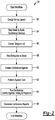
- Figure 2 depicts a DAC workflow 50 in accordance to one embodiment.
- the conference controller 12 is configured to design a layout of the venue 14.
- the conference controller 12 is configured to visually generate a rendering of the venue 14, a seating arrangement (or layout), and a distribution of the plurality of second conference units 20.
- An external device that is not part of the conference controller 12 may be used by the user to create a seating layout of the venue which can be uploaded into the conference controller 12 of the conference controller 12.
- the external device may create the seating layout of the venue 14 in an electronic format (e.g., Portable Network Graphics (PNG), Joint Picture Experts Group (JPEG), Bitmap (BMP), etc.).
- the conference controller 12 may then upload the electronic version of the seating layout such that the conference controller 12 stores the same therein.
- the conference controller 12 includes an image processing algorithm integrated therein for parsing the image of the venue 14 to automatically identify seats, seat numbers, and one or more of the second conference units 20. Figures 3 - 4 as will be described in more detail below may be relevant to operation 52.
- Figure 3 depicts a file open function 80 as provided by the conference controller 12 in accordance to one embodiment.
- the file open function 80 may be used to create a workflow name which can then include information or data related to the venue 14, delegate (e.g., seat number), and agenda (e.g., sequence of topics members of conference would like to discuss along with voting options for each member) for the conference that will occur. Such information may be saved in the conference unit 12. The user may select via the conference controller 12 a particular venue, seat number or delegate, and agenda to correspond to a particular work flow.
- the conference controller 12 may create any number of workflow names that each correspond to a particular conference and venue. It is recognized that any number of venue layouts may be provided or stored in the conference controller 12. Field 82 as shown in Figure 3 illustrates that the conference controller 12 provides a venue design option and device map layout. This will be discussed in more detail below.
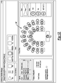
- Figure 4 depicts a venue, delegates, agenda, and reports screen from the file open function of Figure 3 .
- the user may select via the conference controller 12 the venue, delegates, agenda, and various reports for the selected conference name.
- the user may have a bird's eye view of the complete conference including a pictorial representation of the venue, a list of delegates, the agenda, and reports which in turn enables the user quick access to information.
- the conference controller 12 may map various seats as illustrated in the venue 14 to corresponding second conference units 20. This operation may be performed once the second conference units 20 are installed at the venue 14 and the mapping may be performed manually or via uploading, for example, with a text file such as but not limited to, comma-separated values (CSV) file.
- CSV comma-separated values
- Figure 5 depicts a layout design function as provided in the conference controller 12 in accordance to one embodiment. As generally shown at field 92, when the layout is selected in the field 82, a file name is displayed which corresponds to the uploaded seating layout as noted above in connection with operation 52.
- the conference controller 12 may automatically detect seat numbers from the physical image of the venue layout and may also automatically detect device addresses 90 (see Figure 6 ).
- the conference controller 12 includes an image processing algorithm that analyzes the layout to identify objects and to compare each object with various predefined conference system objects as stored in the database (or server) to uniquely identify objects such as chairs, tables, projectors, number, and telephones, etc.
- the device addresses 90 may correspond to a media access control (MAC) address which uniquely identifies a corresponding second conference unit 20.
- MAC media access control
- Screen 94 generally depicts the various seat numbers (e.g., C01 - C06) (or second conference units 20a - 20n) with associated device addresses 90 and device types (e.g., "Type A").
- the device type is also associated with a corresponding conference unit 20.
- the conference controller 12 generates the screen 94 in response to "device map" being selected in field 82.
- the device type corresponds to various types (e.g., A, B, C) as generally shown at 96.
- a "Type A" conference unit 20 may be configured to enable a voting option
- a "Type B” conference unit 20 may be configured as the delegate unit
- a "Type C” conference unit 20 may be configured to provide translations to the attendee seated at the seat number. It is recognized that the second conference unit 20 may not perform the translation per se.
- the Type C conference unit 20 is configured to provide translated audio while a professional translator who is present at the venue 14 articulates the translation in real time which is broadcast to the Type C conference unit 20.
- a user may upload the text file (e.g., CSV file) to the conference controller 12 to perform the mapping of the seat number and device address.
- the conference controller 12 creates a delegate list.
- the conference controller 12 creates a table for storage on the server including the delegates attending the conference and may optionally pre-assign each delegate to a particular seat (or second conference unit 20). Additional information about the delegate, such as the name, contact details, photo, etc. can be provided to the conference controller 12 to be shared across the system 10.
- the conference controller 12 maps (or assigns) the delegates to their respective seats. This condition is generally shown at 102 in Figure 7 . It is recognized that the conference controller 12 may associate any number of associations for both the delegates and seats.
- the conference controller 12 may create an agenda for the conference.
- a conference typically includes a sequence of topics for discussion and voting.
- the conference controller 12 enables the user to create an agenda with a topic for discussion, topic duration (see Figure 7 at 104 for topic of discussion and duration), microphone allocation (see Figure 7 at 106 for allocation), strategy, priority of delegates (see Figure 7 at 107 - microphone allocation priorities - higher ranking attendee granted priority to speak over lower ranking attendee (e.g., president can speak first at any time (e.g., priority first in first out) while mayor can speak if next in turn so long as president is not speaking)), and preventing various delegates from not speaking at all (or allowing delegates the opportunity to speak) (see Figure 7 generally at 108), topics open to vote (see Figure 8 , generally at 122), vote options (see Figure 8 , generally at 124), and voting type (e.g., secret or public) (see Figure 8 , generally at 126).
- topic duration see Figure 7 at 104 for topic of discussion and
- the conference controller 12 may communicate with the various second conference units 20 for enforcing the (i) topic for discussion, (ii) topic duration, (iii) microphone allocation, (iv) speaking privileges, (v) topic open to vote, (vi) vote options, etc. once identified in the conference controller 12.
- the conference controller 12 also provides for the selection of a custom vote (see Figure 8 , generally at 128) in which the user can configure a vote option as "yea' or "nay” etc.
- the conference controller 12 also allows the user to identify which delegate is allowed to vote (see Figure 8 , generally at 130). Again, the information as input into the conference controller 12 may be transmitted to the various second conference units 20 to perform a various operation as instructed by the conference controller 12.
- the conference controller 12 may then transmit such information to the second conference unit 20 positioned at seat number "C02". In this case, the second conference unit 20 assigned to the seat number "C02" will prevent Mr. Will Power from voting.
- the various second conference units 20 (and/or remote conference units 22) will enforce or perform operations as provided by the conference controller 12 in accordance to those specified by the user in the conference controller 12.
- the conference controller 12 is configured to provide feedback on a system test that is performed in the system 10.
- the conference controller 12 may interface with the first conference unit 18, the second conference units 20, and the remote conference units 22 to test various aspects (or perform a poll test) of the same prior to running a live conference.
- the conference controller 12 may detect or identify various units 18, 20, and 22 with various faults so that a system engineer is capable of resolving such faults prior to the conference.
- the conference controller 12 may individually poll each conference unit 18, 20, and 22 to test connectivity, microphone, speaker, etc. as associated with each conference unit 18, 20, and 22 and generates a detailed report which identifies if faults were found during the poll test.
- Figure 9 depicts a test status as provided by the conference controller 12 in accordance to one embodiment.
- the user may select the poll test option such that the conference controller 12 interfaces with the various units 18, 20, and 22 to perform the poll test.
- the conference controller 12 provides a listing of the test status for each device (or unit 18, 20, and 22) that is tested and further indicates if any errors were found and what the error relates to (e.g., microphone, etc.).
- the conference controller 12 also provides/displays an estimated duration for the poll test as it is being performed on a particular conference unit 18, 20, and 22.
- Figure 14 One example of the manner in which the poll test is executed is set forth in connection with Figure 14 which will be described in more detail below.
- the conference controller 12 provides multiple views of various aspects of the system 10 (e.g., master view, agenda, delegates, log, and projections) (see Figure 10 , generally at 138).
- the conference controller 12 also provides for a run conference function (see Figure 10 , generally at 140) which enables control over the conference (e.g., start, pause and stop a conference)
- the venue 14 will be electronically displayed on the conference controller 12 (see Figure 10 , generally at 142) along with the pre-defined agenda for the conference.
- Figure 11 depicts a screen of the conference controller 12 when the conference is active (or has started).
- various speaker lists are provided on the conference controller 12 which indicate (i) which speaker is on a waiting list, (ii) current or active speakers, and (iii) past speakers.
- Figure 12 depicts a projection view as provided on the conference controller 12 while the conference is active.
- the projection view provides an indication as to which screen is projectable (see 145).
- a master screen and a projector #1 are indicated to be projectable on a screen if so desired at the conference.
- Figure 13 depicts a voting view as provided on the conference controller 12 while members of the conference vote on a particular issue.
- the manner in which a particular delegate has voted on a topic is displayed and the overall vote count is maintained while the voting period is open.
- the vote count may be displayed as a bar chart, a pie chart, or vote count.
- the conference controller 12 enables the user to generate reports associated with the conference such as attendee lists, voting results, etc.
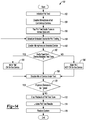
- Figure 14 depicts a method 150 for performing the poll test at any one or more of the units 18, 20, and 22 as initially discussed with the poll test in connection with operation 62 of Figure 2 .
- the conference controller 12 initializes the poll test in the system 10.
- the conference controller 12 transmits a command to the various units 18 and 20 to disable the microphone for each of such units.
- the conference controller 12 controls venue speakers to play an audio tune.
- the venue speakers are within the venue 14 (or conference hall) and are linked to a public address system within the venue 14 or hall.
- the conference controller 12 selects one of the conference units 18, 20 to perform the poll test.
- the conference controller 12 controls the selected conference unit 18, 20 to enable or activate the microphone for receiving an audio input indicative of the audio tune as provided in operation 156.
- the conference controller 12 receives a sampled audio signal from the selected conference unit 18, 20 to determine if the tone as provided on the sampled audio signal matches the audio tune as played in connection with operation 156. If this condition is true, then the method 150 moves to operation 164. If not, then the method 150 moves to operation 166.
- the conference controller 12 indicates that the microphone for the selected conference unit 18, 20 has passed the test.
- the conference controller 12 indicates that the microphone for the selected conference unit 18, 20 is exhibiting a fault condition.
- the conference controller 12 disables the microphone under the test for the selected conference unit 18, 20. In this case, the conference controller 12 transmits the command to the selected conference unit 18, 20 to disable the microphone thereof.
- the conference controller 12 determines if there are any additional conference units 18, 20 that need to be tested. If this condition is true, then the method 150 moves back to operation 158. If not, then the method 150 moves to operation 172.
- the conference controller 12 stops the playback of the audio tune on the venue speakers.
- the conference controller 12 provides the results of the poll test for all of the selected conference units 18, 20.
- the conference controller 12 restores the system 10.
- Figure 15 depicts a method 200 for executing an on-line wizard in accordance to one embodiment.
- the conference controller 12 provides a file open function which enables a user to create a workflow (i.e .,, information or settings related to the venue 14, delegate (e.g., seat number), and agenda (e.g., sequence of topics members of conference would like to discuss along with voting options for each member) for the conference that will occur for the conference, etc.).
- the conference controller 16 may not be communicating to the first conference unit 18 and to the second conference units 20a - 20n.
- the conference controller 12 may be controlled to execute the on-line wizard once it has been determined that information can be transmitted to the first conference unit 18 and the second conference units 20a - 20n.
- the conference controller 12 checks for a valid network and device configuration. For example, the conference controller 12 checks network connectivity and matches device configurations with the first conference unit 18 and the second conference units 20a - 20n (and optionally the remote conference units 22a - 22n). This operation ensures that there is a match between the conference controller 12, the first conference unit 18, and the second conference units 20a - 20n.
- the conference controller 12 performs system 10 learning.
- the first conference unit 18 and/or the second conference units 20a - 20n may be in "an unlearned state" which means that such units may not have a physical network address assigned.
- the conference controller 12 checks for this state and automatically initiates "an auto learning" operation so that all of the units 18, 20a - 20n, and/or 22a - 22n have an address assigned thereto and that the system 10 as a whole is stable.
- the conference controller 12 matches the various conference units 18, 20a - 20n, and 22a - 22n as detected in the network ( i.e ., when the conference controller 12 is on-line) to the various conference units 18, 20a - 20n, and 22a - 22n as established when the conference controller 12 is off-line.
- the conference controller 12 matches the conference units 18, 20a - 20n, and 22a - 22n as electronically detected in the system 10 to the various conference units 18, 20a - 20n, and 22a - 22n established when the conference controller 12 is off-line to determine if there is a match. If there is a mismatch, the conference controller 12 may automatically resolve the mismatch or prompt the user to resolve the mismatch.
- the conference controller 12 may then apply the various settings or information such as but not limited to, volume level, system timers, device (or conference unit) availability, voting options, etc. for the particular units 18, 20a - 20n, and 22a - 22n.
Description
- Aspects disclosed herein generally relate to a system and method for digital audio conference workflow management.
- A digital audio conference unit includes a microphone, a speaker, and optional display and buttons for user input. A number of such conference units are networked together along with a central conference controller to form a conference system. The conference system facilitates a controlled discussion, voting, translation services, and remote dialing. The conference system as known today may not include adequate levels of conference setup configurability, testing, and control of the overall installation of devices.
- Document
US 2007/0112563 A1 discloses a model sample audio file stored in a memory on a computing device which is played through a loudspeaker connected with a computer system. The sound generated thereby is captured by a microphone connected with the computer system to create a captured audio signal. The captured audio signal is correlated with the sample audio signal to determine the fidelity of the captured audio signal. An algorithm for correlation of the captured audio signal with the sample audio signal may consider volume and frequency characteristics of the audio signals. A device quality score is computed and an optimal audio device configuration may be automatically selected by the computer system. - It is the object of the present invention to provide an improved apparatus for automatically testing and muting a microphone that is not operating properly in a conference, as well as a corresponding method. This object is solved by the subject matter of the independent claims. Preferred embodiments are defined by the dependent claims.
- In an embodiment, an apparatus for use in a digital audio conference is provided. The apparatus comprises a conference unit including a microphone and is operably coupled to a conference controller that manages the audio conference. The conference unit is programmed to receive a first command from the conference controller to enable the microphone to receive a first audio signal from at least one first loudspeaker in a venue for the audio conference and to transmit a sampled audio signal of the first audio signal to the conference controller to determine if the microphone for the conference unit is operating properly. The conference unit is further programmed to receive a second command from the conference controller to disable the microphone if the sampled audio signal does not match the first audio signal.
- In another embodiment, a method for use in digital audio conference is provided. The method comprises receiving a first command at a conference unit that includes a microphone from a conference controller to enable the microphone to receive a first audio signal from at least one first loudspeaker in a venue for the audio conference, transmitting a sampled audio signal of the first audio signal to the conference controller to determine if the microphone for the conference unit is operating properly, and receiving a second command from the conference controller to disable the microphone if the sampled audio signal does not match the first audio signal.
- The embodiments of the present disclosure are pointed out with particularity in the appended claims. However, other features of the various embodiments will become more apparent and will be best understood by referring to the following detailed description in conjunction with the accompany drawings in which:
-
Figure 1 depicts a digital audio conference (DAC) system in accordance to one embodiment; -
Figure 2 depicts a DAC workflow in accordance to one embodiment; -
Figure 3 depicts a file open function provided by a DAC tool in accordance to one embodiment; -
Figure 4 depicts a venue, delegates, agenda, and reports screen for a selected conference name as generated by the DAC tool in accordance to one embodiment; -
Figure 5 depicts a layout design function as depicted in the DAC tool in accordance to one embodiment; -
Figure 6 depicts a set design mapping function as depicted in the DAC tool in accordance to one embodiment; -
Figure 7 depicts a topic setup function as provided by the DAC tool in accordance to one embodiment; -
Figure 8 depicts a voting setup function as provided by the DAC tool in accordance to one embodiment; -
Figure 9 depicts a poll test function as provided by the DAC tool in accordance to one embodiment; -
Figure 10 depicts a master view of a run conference function as provided by the DAC tool in accordance to one embodiment; -
Figure 11 depicts a delegates view of the run conference function as provided by DAC tool in accordance to one embodiment; -
Figure 12 depicts a projection view of the run conference function as provided by the DAC tool in accordance to one embodiment; -
Figure 13 depicts a generate conference report function as provided by the DAC tool in accordance to one embodiment; -
Figure 14 depicts a method for performing the poll test in accordance to one embodiment; and -
Figure 15 depicts a method for executing an on-line wizard in accordance to one embodiment. - As required, detailed embodiments of the present disclosure are provided herein; however, it is to be understood that the disclosed embodiments are merely illustrative of the disclosure that may be embodied in various and alternative forms. The figures are not necessarily to scale; some features may be exaggerated or minimized to show details of particular components. Therefore, specific structural and functional details disclosed herein are not to be interpreted as limiting, but merely as a representative basis for teaching one skilled in the art to variously employ the present invention.
- The embodiments of the present disclosure generally provide for a plurality of circuits or other electrical devices. All references to the circuits and other electrical devices and the functionality provided by each, are not intended to be limited to encompassing only what is illustrated and described herein. While particular labels may be assigned to the various circuits or other electrical devices disclosed, such labels are not intended to limit the scope of operation for the circuits and the other electrical devices. Such circuits and other electrical devices may be combined with each other and/or separated in any manner based on the particular type of electrical implementation that is desired.
- It is recognized that any circuit or other electrical device disclosed herein may include any number of microprocessors, integrated circuits, memory devices (e.g., FLASH, random access memory (RAM), read only memory (ROM), electrically programmable read only memory (EPROM), electrically erasable programmable read only memory (EEPROM), or other suitable variants thereof) and software which co-act with one another to perform operation(s) disclosed herein. In addition, any one or more of the electrical devices as disclosed herein may be configured to execute a computer-program that is embodied in a non-transitory computer readable medium that is programed to perform any number of the functions as disclosed herein.
- In general, the present disclosure provides a digital audio conference (DAC) tool that is executed on a conference controller for providing a streamlined workflow management of the DAC which starts, for example, by creating a visual representation of a venue to management of speakers during a live conference. The tool provides (via the conference controller), but not limited to, various methods to load a venue layout, automatically identify seats in a conference room, map seats to audio conference devices, interface with an integrated database (on the conference controller) to manage delegate information, visually allocate time to speak for each delegate linked to an agenda, create voting options, dynamically check status of the audio conference devices prior to starting a conference, run the conference in manual or in an auto-pilot mode, provide real time status of speakers (e.g., inactive, waiting, active, etc.) and to create, control, log and save various parameters before, during and after an audio conference. In addition, the tool enables data to be linked to a server for additional integration on delegate checkin, realtime information on updating/broadcasting on the status of the conference in addition to remote participation.
-
Figure 1 depicts a digital audio conference (DAC)system 10 in accordance to one embodiment. Thesystem 10 generally includes aconference controller 12 that is positioned in avenue 14 where an audio/video conference may take place. Theconference controller 12 includes aDAC tool 16 for enabling a user to generate various aspects of workflow management of the A/V conference. In one example, thetool 16 may comprise logic and is embodied in a non-transitory computer readable medium that is programmed to perform any number of operations disclosed herein. Theconference controller 12 includes hardware for executing the logic on the computer readable medium to perform the various operations disclosed herein. Theconference controller 12 interfaces with thetool 16 to provide workflow management of the A/V conference in thevenue 14. Theconference controller 12 also includes a server (not shown) for storing and providing various aspects of the audio/video conference. - The
conference controller 12 is operably coupled to afirst conference unit 18. Thefirst conference unit 18 is operably coupled to a plurality ofsecond conference units 20a - 20n ("20). In general, eachconference unit conference units first conference unit 18 may include more functionality than one or more of the plurality ofsecond conference units 20. For example, thefirst conference unit 18 may be allocated to a chairperson of a conference. In this case, thefirst conference unit 18 may include additional features to control the conference such as enabling/disabling a microphone (on a second conference unit 20), controlling an agenda, initiating voting, and controlling a transmission of data to projector(s), etc. One or more of the plurality of thesecond conference units 20 may be configured or set up as (i) a voting unit (where the participant may be enabled to vote on various issues presented in the conference) (ii) a delegate unit, or (iii) an interpreter unit (e.g., participant in conference can get live feed of audio that is translated in participant's native language). A delegate unit is generally asecond conference unit 20 that enables an individual attending the conference to seek access to the microphone, speak when the microphone is activated, vote during the conference and also listen to the conference via the speaker. - The
DAC system 10 further includes a plurality ofremote conference units 22a-22n ("22") that is positioned outside of thevenue 14. Acommunication bus 24 is operably coupled to the plurality ofremote conference units 22a-22n for enabling data transfer between theconference controller 12, thefirst conference unit 18, the second plurality ofconference units 20, and the plurality ofconference units 22a-22n. In one example, thecommunication bus 24 may implement a Transmission Control Protocol/Internet Protocol (TCP/IP) (or other suitable alternative) for enabling communication between theconference controller 12, thefirst conference unit 18, thesecond conference units 20, and theremote conference units 22a-22n. - The
tool 16 interfaces with theconference controller 12 to enable a user to provide workflow management of the A/V conference for thefirst conference unit 18 and thesecond conference units 20 in thevenue 14 and for the plurality of remote conference units 22. Theconference controller 12 may enable a user to (i) load a layout of thevenue 14, (ii) automatically identify a seat in a conference room; (iii) associate the seat to aparticular conference unit 20 and 22, (iv) interface with the server (e.g., an integrated database) to manage delegate information, (v) visually allocate time to speak for each delegate linked to an agenda and further linked to aparticular conference unit 20 and 22, (vi) create similar or different voting options for eachconference unit 20 and 22, (vii) dynamically check status of theconference units 20 and 22 prior to starting a conference, (viii) run the conference in manual or in an auto-pilot mode, (ix) provide real time status of speakers (e.g., inactive, waiting, active, etc.) and (x) create, control, log and save various parameters before, during and after an audio conference. In addition, theconference controller 12 enables data to be linked to the server of theconference controller 12 for additional integration on delegate check-in (e.g., users at correspondingconference units 20 and 22), real time information on updating/broadcasting status of the conference in addition to remote participation with the remote conference units 22. -
Figure 2 depicts aDAC workflow 50 in accordance to one embodiment. - In
operation 52, theconference controller 12 is configured to design a layout of thevenue 14. For example, theconference controller 12 is configured to visually generate a rendering of thevenue 14, a seating arrangement (or layout), and a distribution of the plurality ofsecond conference units 20. An external device that is not part of theconference controller 12 may be used by the user to create a seating layout of the venue which can be uploaded into theconference controller 12 of theconference controller 12. For example, the external device may create the seating layout of thevenue 14 in an electronic format (e.g., Portable Network Graphics (PNG), Joint Picture Experts Group (JPEG), Bitmap (BMP), etc.). Theconference controller 12 may then upload the electronic version of the seating layout such that theconference controller 12 stores the same therein. Theconference controller 12 includes an image processing algorithm integrated therein for parsing the image of thevenue 14 to automatically identify seats, seat numbers, and one or more of thesecond conference units 20.Figures 3 - 4 as will be described in more detail below may be relevant tooperation 52. - For example,
Figure 3 depicts a fileopen function 80 as provided by theconference controller 12 in accordance to one embodiment. The fileopen function 80 may be used to create a workflow name which can then include information or data related to thevenue 14, delegate (e.g., seat number), and agenda (e.g., sequence of topics members of conference would like to discuss along with voting options for each member) for the conference that will occur. Such information may be saved in theconference unit 12. The user may select via the conference controller 12 a particular venue, seat number or delegate, and agenda to correspond to a particular work flow. - As shown, the
conference controller 12 may create any number of workflow names that each correspond to a particular conference and venue. It is recognized that any number of venue layouts may be provided or stored in theconference controller 12.Field 82 as shown inFigure 3 illustrates that theconference controller 12 provides a venue design option and device map layout. This will be discussed in more detail below. - In addition,
Figure 4 depicts a venue, delegates, agenda, and reports screen from the file open function ofFigure 3 . The user may select via theconference controller 12 the venue, delegates, agenda, and various reports for the selected conference name. In general, the user may have a bird's eye view of the complete conference including a pictorial representation of the venue, a list of delegates, the agenda, and reports which in turn enables the user quick access to information. - Referring back to
Figure 2 , inoperation 54, theconference controller 12 may map various seats as illustrated in thevenue 14 to correspondingsecond conference units 20. This operation may be performed once thesecond conference units 20 are installed at thevenue 14 and the mapping may be performed manually or via uploading, for example, with a text file such as but not limited to, comma-separated values (CSV) file. This condition is further illustrated inFigure 5 which depicts a layout design function as provided in theconference controller 12 in accordance to one embodiment. As generally shown atfield 92, when the layout is selected in thefield 82, a file name is displayed which corresponds to the uploaded seating layout as noted above in connection withoperation 52. As also shown at 92, theconference controller 12 may automatically detect seat numbers from the physical image of the venue layout and may also automatically detect device addresses 90 (seeFigure 6 ). As noted above, theconference controller 12 includes an image processing algorithm that analyzes the layout to identify objects and to compare each object with various predefined conference system objects as stored in the database (or server) to uniquely identify objects such as chairs, tables, projectors, number, and telephones, etc. In general, the device addresses 90 may correspond to a media access control (MAC) address which uniquely identifies a correspondingsecond conference unit 20. - The
seat mapping operation 54 as noted in connection withFigure 2 is set forth inFigure 6 .Screen 94 generally depicts the various seat numbers (e.g., C01 - C06) (orsecond conference units 20a - 20n) with associated device addresses 90 and device types (e.g., "Type A"). The device type is also associated with acorresponding conference unit 20. Theconference controller 12 generates thescreen 94 in response to "device map" being selected infield 82. In general, the device type corresponds to various types (e.g., A, B, C) as generally shown at 96. In one example, a "Type A"conference unit 20 may be configured to enable a voting option, a "Type B"conference unit 20 may be configured as the delegate unit, and a "Type C"conference unit 20 may be configured to provide translations to the attendee seated at the seat number. It is recognized that thesecond conference unit 20 may not perform the translation per se. However, the TypeC conference unit 20 is configured to provide translated audio while a professional translator who is present at thevenue 14 articulates the translation in real time which is broadcast to the TypeC conference unit 20. As generally shown at 98, a user may upload the text file (e.g., CSV file) to theconference controller 12 to perform the mapping of the seat number and device address. - Referring back to
Figure 2 , inoperation 56, theconference controller 12 creates a delegate list. In this case, theconference controller 12 creates a table for storage on the server including the delegates attending the conference and may optionally pre-assign each delegate to a particular seat (or second conference unit 20). Additional information about the delegate, such as the name, contact details, photo, etc. can be provided to theconference controller 12 to be shared across thesystem 10. - In
operation 58, theconference controller 12 maps (or assigns) the delegates to their respective seats. This condition is generally shown at 102 inFigure 7 . It is recognized that theconference controller 12 may associate any number of associations for both the delegates and seats. - Referring back to
Figure 2 , inoperation 60, theconference controller 12 may create an agenda for the conference. In general, a conference typically includes a sequence of topics for discussion and voting. Theconference controller 12 enables the user to create an agenda with a topic for discussion, topic duration (seeFigure 7 at 104 for topic of discussion and duration), microphone allocation (seeFigure 7 at 106 for allocation), strategy, priority of delegates (seeFigure 7 at 107 - microphone allocation priorities - higher ranking attendee granted priority to speak over lower ranking attendee (e.g., president can speak first at any time (e.g., priority first in first out) while mayor can speak if next in turn so long as president is not speaking)), and preventing various delegates from not speaking at all (or allowing delegates the opportunity to speak) (seeFigure 7 generally at 108), topics open to vote (seeFigure 8 , generally at 122), vote options (seeFigure 8 , generally at 124), and voting type (e.g., secret or public) (seeFigure 8 , generally at 126). - It is recognized that the
conference controller 12 may communicate with the varioussecond conference units 20 for enforcing the (i) topic for discussion, (ii) topic duration, (iii) microphone allocation, (iv) speaking privileges, (v) topic open to vote, (vi) vote options, etc. once identified in theconference controller 12. Theconference controller 12 also provides for the selection of a custom vote (seeFigure 8 , generally at 128) in which the user can configure a vote option as "yea' or "nay" etc. Theconference controller 12 also allows the user to identify which delegate is allowed to vote (seeFigure 8 , generally at 130). Again, the information as input into theconference controller 12 may be transmitted to the varioussecond conference units 20 to perform a various operation as instructed by theconference controller 12. For example, assuming delegate Mr. Will Power is identified as a delegate that is not allowed to vote (seeFigure 8 , generally at 130), theconference controller 12 may then transmit such information to thesecond conference unit 20 positioned at seat number "C02". In this case, thesecond conference unit 20 assigned to the seat number "C02" will prevent Mr. Will Power from voting. In general, the various second conference units 20 (and/or remote conference units 22) will enforce or perform operations as provided by theconference controller 12 in accordance to those specified by the user in theconference controller 12. - Referring back to
Figure 2 , inoperation 62, theconference controller 12 is configured to provide feedback on a system test that is performed in thesystem 10. For example, theconference controller 12 may interface with thefirst conference unit 18, thesecond conference units 20, and the remote conference units 22 to test various aspects (or perform a poll test) of the same prior to running a live conference. Theconference controller 12 may detect or identifyvarious units conference controller 12 may individually poll eachconference unit conference unit -
Figure 9 depicts a test status as provided by theconference controller 12 in accordance to one embodiment. As generally shown at 132, the user may select the poll test option such that theconference controller 12 interfaces with thevarious units conference controller 12 provides a listing of the test status for each device (orunit conference controller 12 also provides/displays an estimated duration for the poll test as it is being performed on aparticular conference unit Figure 14 which will be described in more detail below. - Referring back to
Figure 2 , in operation 64, theconference controller 12 provides multiple views of various aspects of the system 10 (e.g., master view, agenda, delegates, log, and projections) (seeFigure 10 , generally at 138). Theconference controller 12 also provides for a run conference function (seeFigure 10 , generally at 140) which enables control over the conference (e.g., start, pause and stop a conference) Thevenue 14 will be electronically displayed on the conference controller 12 (seeFigure 10 , generally at 142) along with the pre-defined agenda for the conference.Figure 11 depicts a screen of theconference controller 12 when the conference is active (or has started). As generally shown at 144, various speaker lists are provided on theconference controller 12 which indicate (i) which speaker is on a waiting list, (ii) current or active speakers, and (iii) past speakers. -
Figure 12 depicts a projection view as provided on theconference controller 12 while the conference is active. The projection view provides an indication as to which screen is projectable (see 145). As shown, a master screen and aprojector # 1 are indicated to be projectable on a screen if so desired at the conference.Figure 13 depicts a voting view as provided on theconference controller 12 while members of the conference vote on a particular issue. As shown at 146, the manner in which a particular delegate has voted on a topic is displayed and the overall vote count is maintained while the voting period is open. In addition, the vote count may be displayed as a bar chart, a pie chart, or vote count. - Referring back to
Figure 2 , inoperation 66, theconference controller 12 enables the user to generate reports associated with the conference such as attendee lists, voting results, etc. -
Figure 14 depicts amethod 150 for performing the poll test at any one or more of theunits operation 62 ofFigure 2 . - In
operation 152, theconference controller 12 initializes the poll test in thesystem 10. - In
operation 154, theconference controller 12 transmits a command to thevarious units - In
operation 156, theconference controller 12 controls venue speakers to play an audio tune. The venue speakers are within the venue 14 (or conference hall) and are linked to a public address system within thevenue 14 or hall. - In
operation 158, theconference controller 12 selects one of theconference units - In
operation 160, theconference controller 12 controls the selectedconference unit operation 156. - In
operation 162, theconference controller 12 receives a sampled audio signal from the selectedconference unit operation 156. If this condition is true, then themethod 150 moves tooperation 164. If not, then themethod 150 moves tooperation 166. - In
operation 164, theconference controller 12 indicates that the microphone for the selectedconference unit - In
operation 166, theconference controller 12 indicates that the microphone for the selectedconference unit - In
operation 168, theconference controller 12 disables the microphone under the test for the selectedconference unit conference controller 12 transmits the command to the selectedconference unit - In
operation 170, theconference controller 12 determines if there are anyadditional conference units method 150 moves back tooperation 158. If not, then themethod 150 moves tooperation 172. - In
operation 172, theconference controller 12 stops the playback of the audio tune on the venue speakers. - In
operation 174, theconference controller 12 provides the results of the poll test for all of the selectedconference units - In
operation 176, theconference controller 12 restores thesystem 10. -
Figure 15 depicts amethod 200 for executing an on-line wizard in accordance to one embodiment. As noted above, theconference controller 12 provides a file open function which enables a user to create a workflow (i.e.,, information or settings related to thevenue 14, delegate (e.g., seat number), and agenda (e.g., sequence of topics members of conference would like to discuss along with voting options for each member) for the conference that will occur for the conference, etc.). As the user creates the at least portions of the conference workflow, theconference controller 16 may not be communicating to thefirst conference unit 18 and to thesecond conference units 20a - 20n. Theconference controller 12 may be controlled to execute the on-line wizard once it has been determined that information can be transmitted to thefirst conference unit 18 and thesecond conference units 20a - 20n. - In
operation 202, theconference controller 12 checks for a valid network and device configuration. For example, theconference controller 12 checks network connectivity and matches device configurations with thefirst conference unit 18 and thesecond conference units 20a - 20n (and optionally theremote conference units 22a - 22n). This operation ensures that there is a match between theconference controller 12, thefirst conference unit 18, and thesecond conference units 20a - 20n. - In
operation 204, theconference controller 12 performssystem 10 learning. For example, thefirst conference unit 18 and/or thesecond conference units 20a - 20n may be in "an unlearned state" which means that such units may not have a physical network address assigned. Theconference controller 12 checks for this state and automatically initiates "an auto learning" operation so that all of theunits system 10 as a whole is stable. - In
operation 206, theconference controller 12 matches thevarious conference units conference controller 12 is on-line) to thevarious conference units conference controller 12 is off-line. For example, theconference controller 12 matches theconference units system 10 to thevarious conference units conference controller 12 is off-line to determine if there is a match. If there is a mismatch, theconference controller 12 may automatically resolve the mismatch or prompt the user to resolve the mismatch. - In
operation 208, theconference controller 12 may then apply the various settings or information such as but not limited to, volume level, system timers, device (or conference unit) availability, voting options, etc. for theparticular units - While exemplary embodiments are described above, it is not intended that these embodiments describe all possible forms of the invention. Rather, the words used in the specification are words of description rather than limitation, and it is understood that various changes may be made without departing from the scope of the invention. Additionally, the features of various implementing embodiments may be combined to form further embodiments of the invention.
Claims (7)
- An apparatus for use in a digital audio conference, the apparatus comprising:
a conference unit (18) including a microphone that is operably coupled to a conference controller (12) that manages the audio conference; the conference unit (18) being programmed to:receive a first command from the conference controller (12) to enable the microphone to receive a first audio signal from at least one first loudspeaker in a venue (14) for the audio conference;transmit a sampled audio signal of the first audio signal to the conference controller (12) to determine if the microphone for the conference unit (18) is operating properly; andreceive a second command from the conference controller (12) to disable the microphone if the sampled audio signal does not match the first audio signal. - A method for use in digital audio conference, the method comprising:receiving (160), at a conference unit (18) that includes a microphone that is operably coupled to a conference controller (12), a first command from the conference controller (12) to enable the microphone to receive a first audio signal from at least one first loudspeaker in a venue (14) for the audio conference;transmitting, from the conference unit (18), a sampled audio signal of the first audio signal to the conference controller (12) to determine if the microphone for the conference unit (18) is operating properly; andreceiving (168), in the conference unit (18), a second command from the conference controller (12) to disable the microphone if the sampled audio signal does not match the first audio signal.
- The method of claim 2 further comprising controlling the conference unit (18) to activate the microphone after receiving the first command at the conference unit (18) to enable the microphone to receive a first audio signal from at least one first loudspeaker in a venue (14) for the audio conference.
- The method of claim 3 further comprising comparing a tone on the sampled audio signal to the first audio signal to determine if the microphone for the conference unit (18) is operating properly after transmitting the sampled audio signal.
- The method of claim 4 further comprising determining that the microphone for the conference unit (18) is not properly working if the tone of the sampled audio signal does not match the first audio signal.
- The method of claim 5 further comprising determining that the microphone for the conference unit (18) is properly working if the tone of the samples audio signal matches the first audio signal.
- A computer-program product embodied in a non-transitory computer readable medium that is programmed to manage the digital audio conference including a plurality of conference units (18) and each conference unit (18) including a microphone, the computer-program product comprising instructions to perform the method according to claims 2 - 6.
Applications Claiming Priority (2)
| Application Number | Priority Date | Filing Date | Title |
|---|---|---|---|
| US201361845165P | 2013-07-11 | 2013-07-11 | |
| PCT/US2014/046330 WO2015006681A1 (en) | 2013-07-11 | 2014-07-11 | System and method for digital audio conference workflow management |
Publications (3)
| Publication Number | Publication Date |
|---|---|
| EP3020183A1 EP3020183A1 (en) | 2016-05-18 |
| EP3020183A4 EP3020183A4 (en) | 2017-05-03 |
| EP3020183B1 true EP3020183B1 (en) | 2019-12-11 |
Family
ID=52280636
Family Applications (1)
| Application Number | Title | Priority Date | Filing Date |
|---|---|---|---|
| EP14822334.0A Active EP3020183B1 (en) | 2013-07-11 | 2014-07-11 | System and method for digital audio conference workflow management |
Country Status (4)
| Country | Link |
|---|---|
| US (1) | US10367861B2 (en) |
| EP (1) | EP3020183B1 (en) |
| CN (1) | CN105359499B (en) |
| WO (1) | WO2015006681A1 (en) |
Families Citing this family (8)
| Publication number | Priority date | Publication date | Assignee | Title |
|---|---|---|---|---|
| US10381046B2 (en) * | 2014-07-16 | 2019-08-13 | United States Bankruptcy Court For The District Of Utah | Apparatus and methods for recording audio and video |
| JP6719785B2 (en) * | 2016-02-29 | 2020-07-08 | 株式会社オーディオテクニカ | Conference system |
| CN107548564B (en) * | 2016-04-29 | 2021-02-26 | 华为技术有限公司 | Method, device, terminal and storage medium for determining voice input abnormity |
| WO2020033595A1 (en) | 2018-08-07 | 2020-02-13 | Pangissimo, LLC | Modular speaker system |
| WO2022136854A1 (en) * | 2020-12-21 | 2022-06-30 | Civico Limited | Conference apparatus and method for providing a unified meeting environment |
| WO2022263814A1 (en) * | 2021-06-15 | 2022-12-22 | Civico Limited | Conference apparatus and method |
| US11647060B1 (en) * | 2022-03-17 | 2023-05-09 | Lenovo (United States) Inc. | Use of audio and image data of video conference to dynamically generate interactive graphical elements |
| US11956286B1 (en) * | 2022-11-25 | 2024-04-09 | Microsoft Technology Licensing, Llc | Dynamically controlled participation allocations for communication sessions |
Family Cites Families (26)
| Publication number | Priority date | Publication date | Assignee | Title |
|---|---|---|---|---|
| US6292769B1 (en) * | 1995-02-14 | 2001-09-18 | America Online, Inc. | System for automated translation of speech |
| CA2397493A1 (en) * | 2000-01-27 | 2001-08-02 | Cytovia, Inc. | Substituted nicotinamides and analogs as activators of caspases and inducers of apoptosis and the use thereof |
| US20060008817A1 (en) * | 2000-12-08 | 2006-01-12 | Invitrogen Corporation | Methods and compositions for generating recombinant nucleic acid molecules |
| US7075921B2 (en) * | 2001-01-30 | 2006-07-11 | Estara, Inc. | Remote media control for voice over internet telephony and related applications |
| US20030163537A1 (en) * | 2001-11-27 | 2003-08-28 | International Business Machines Corporation | Method and apparatus for handling conversation threads and message groupings as a single entity |
| US20030103075A1 (en) * | 2001-12-03 | 2003-06-05 | Rosselot Robert Charles | System and method for control of conference facilities and equipment |
| US7978838B2 (en) * | 2001-12-31 | 2011-07-12 | Polycom, Inc. | Conference endpoint instructing conference bridge to mute participants |
| US7010107B1 (en) * | 2002-12-20 | 2006-03-07 | Yong Lee | Internet conference call bridge management system |
| DE10330594A1 (en) * | 2003-07-07 | 2005-03-03 | Siemens Ag | Device for use in the medical field and method for its maintenance |
| JP3891153B2 (en) * | 2003-07-31 | 2007-03-14 | ソニー株式会社 | Telephone device |
| US20050164154A1 (en) * | 2004-01-23 | 2005-07-28 | Geodesic Dynamics | Demand initiated customized e-learning system |
| US7660428B2 (en) * | 2004-10-25 | 2010-02-09 | Polycom, Inc. | Ceiling microphone assembly |
| DE102004052487B4 (en) * | 2004-10-28 | 2007-09-06 | Sennheiser Electronic Gmbh & Co. Kg | Conference station and conference system |
| KR101332210B1 (en) * | 2005-06-30 | 2013-11-25 | 인튜어티브 서지컬 인코포레이티드 | Indicator for tool state and communication in multiarm robotic telesurgery |
| US8000466B2 (en) * | 2005-09-01 | 2011-08-16 | Siemens Enterprise Communications, Inc. | Method and apparatus for multiparty collaboration enhancement |
| US20070112563A1 (en) | 2005-11-17 | 2007-05-17 | Microsoft Corporation | Determination of audio device quality |
| JP4802873B2 (en) | 2006-06-09 | 2011-10-26 | 富士ゼロックス株式会社 | Browsing management device, management method thereof, and program |
| CN101364916B (en) | 2008-08-25 | 2010-12-15 | 浙江天地人科技有限公司 | Intelligent conference seat management system |
| NO333026B1 (en) * | 2008-09-17 | 2013-02-18 | Cisco Systems Int Sarl | Control system for a local telepresence video conferencing system and method for establishing a video conferencing call. |
| US20100085415A1 (en) * | 2008-10-02 | 2010-04-08 | Polycom, Inc | Displaying dynamic caller identity during point-to-point and multipoint audio/videoconference |
| WO2011091604A1 (en) * | 2010-01-29 | 2011-08-04 | 华为终端有限公司 | Method, apparatus and system for video communication |
| US20120170726A1 (en) * | 2011-01-05 | 2012-07-05 | Parlor.Fm., Inc. | Media Link |
| JP2012234233A (en) * | 2011-04-28 | 2012-11-29 | Hitachi Ltd | Tv conference reservation system |
| US8850522B2 (en) * | 2012-03-27 | 2014-09-30 | Microsoft Corporation | Participant authentication and authorization for joining a private conference event via a conference event environment system |
| JP6141449B2 (en) * | 2012-12-27 | 2017-06-07 | ローベルト ボツシユ ゲゼルシヤフト ミツト ベシユレンクテル ハフツングRobert Bosch Gmbh | Audio stream device |
| US9420434B2 (en) * | 2013-05-07 | 2016-08-16 | Revo Labs, Inc. | Generating a warning message if a portable part associated with a wireless audio conferencing system is not charging |
-
2014
- 2014-07-11 CN CN201480039170.9A patent/CN105359499B/en active Active
- 2014-07-11 US US14/904,088 patent/US10367861B2/en active Active
- 2014-07-11 WO PCT/US2014/046330 patent/WO2015006681A1/en active Application Filing
- 2014-07-11 EP EP14822334.0A patent/EP3020183B1/en active Active
Non-Patent Citations (1)
| Title |
|---|
| None * |
Also Published As
| Publication number | Publication date |
|---|---|
| CN105359499A (en) | 2016-02-24 |
| CN105359499B (en) | 2019-04-30 |
| EP3020183A4 (en) | 2017-05-03 |
| WO2015006681A1 (en) | 2015-01-15 |
| EP3020183A1 (en) | 2016-05-18 |
| US10367861B2 (en) | 2019-07-30 |
| US20160134668A1 (en) | 2016-05-12 |
Similar Documents
| Publication | Publication Date | Title |
|---|---|---|
| EP3020183B1 (en) | System and method for digital audio conference workflow management | |
| US9307197B2 (en) | Transmission management apparatus | |
| CN105610777B (en) | Remote living broadcast method and system | |
| US20170086233A1 (en) | Connection method for multimedia playing device, main device, and control terminal | |
| CN103636197A (en) | Transmission terminal, image display control method, image display control program, recording medium, and transmission system | |
| US10735477B2 (en) | System, apparatus and associated methodology for establishing multiple data communications between terminals | |
| KR102360662B1 (en) | Caller queue process and system for managing incoming video callers | |
| US10187702B2 (en) | Systems and methods to test media devices | |
| US20170048284A1 (en) | Non-transitory computer readable medium, information processing apparatus, and information processing system | |
| CN103270751A (en) | Transmission management system, transmission system, transmission management method, transmission management program, computer readable information recording medium, program providing system, and maintenance system | |
| US10044976B2 (en) | Information processing apparatus, image display method, and communications system | |
| JP2006237864A (en) | Terminal for processing voice signals of a plurality of talkers, server apparatus, and program | |
| JP6484934B2 (en) | COMMUNICATION DEVICE, COMMUNICATION SYSTEM, COMMUNICATION MANAGEMENT SYSTEM, COMMUNICATION CONTROL METHOD, AND PROGRAM | |
| CN108964927B (en) | Power over Ethernet (PoE) self-adaption method and device | |
| CN107734364A (en) | Projecting apparatus control method, system and computer-readable recording medium | |
| CN106533823B (en) | Automatic test system and method and recyclable sending device thereof | |
| US20160269203A1 (en) | Information processing apparatus, information processing system, and information processing method | |
| CN105959126A (en) | Dynamic background sharing method and device in audio chatting room | |
| US9781384B2 (en) | Information processing system, information processing apparatus, information processing method, and recording medium | |
| US9960925B2 (en) | Server apparatus program, server apparatus, and communication apparatus program | |
| JP7020132B2 (en) | Terminal equipment, information processing methods, programs, communication systems | |
| JP2021190751A (en) | Server device, server system, information processing method, and program | |
| JP2017158137A (en) | Conference system | |
| EP3651025A1 (en) | Slave electronic device, master electronic device, control network and method | |
| KR101835091B1 (en) | Chatting method and chatting system for learning language |
Legal Events
| Date | Code | Title | Description |
|---|---|---|---|
| PUAI | Public reference made under article 153(3) epc to a published international application that has entered the european phase |
Free format text: ORIGINAL CODE: 0009012 |
|
| 17P | Request for examination filed |
Effective date: 20160111 |
|
| AK | Designated contracting states |
Kind code of ref document: A1 Designated state(s): AL AT BE BG CH CY CZ DE DK EE ES FI FR GB GR HR HU IE IS IT LI LT LU LV MC MK MT NL NO PL PT RO RS SE SI SK SM TR |
|
| AX | Request for extension of the european patent |
Extension state: BA ME |
|
| DAX | Request for extension of the european patent (deleted) | ||
| RIC1 | Information provided on ipc code assigned before grant |
Ipc: H04R 3/00 20060101ALI20170112BHEP Ipc: H04M 3/42 20060101ALI20170112BHEP Ipc: H04L 29/06 20060101ALI20170112BHEP Ipc: H04M 3/28 20060101ALI20170112BHEP Ipc: H04R 29/00 20060101ALI20170112BHEP Ipc: H04M 3/56 20060101AFI20170112BHEP |
|
| A4 | Supplementary search report drawn up and despatched |
Effective date: 20170405 |
|
| RIC1 | Information provided on ipc code assigned before grant |
Ipc: H04R 3/00 20060101ALI20170330BHEP Ipc: H04R 29/00 20060101ALI20170330BHEP Ipc: H04M 3/56 20060101AFI20170330BHEP Ipc: H04M 3/42 20060101ALI20170330BHEP Ipc: H04M 3/28 20060101ALI20170330BHEP Ipc: H04L 29/06 20060101ALI20170330BHEP |
|
| GRAP | Despatch of communication of intention to grant a patent |
Free format text: ORIGINAL CODE: EPIDOSNIGR1 |
|
| STAA | Information on the status of an ep patent application or granted ep patent |
Free format text: STATUS: GRANT OF PATENT IS INTENDED |
|
| INTG | Intention to grant announced |
Effective date: 20190719 |
|
| GRAS | Grant fee paid |
Free format text: ORIGINAL CODE: EPIDOSNIGR3 |
|
| GRAA | (expected) grant |
Free format text: ORIGINAL CODE: 0009210 |
|
| STAA | Information on the status of an ep patent application or granted ep patent |
Free format text: STATUS: THE PATENT HAS BEEN GRANTED |
|
| AK | Designated contracting states |
Kind code of ref document: B1 Designated state(s): AL AT BE BG CH CY CZ DE DK EE ES FI FR GB GR HR HU IE IS IT LI LT LU LV MC MK MT NL NO PL PT RO RS SE SI SK SM TR |
|
| REG | Reference to a national code |
Ref country code: GB Ref legal event code: FG4D |
|
| REG | Reference to a national code |
Ref country code: CH Ref legal event code: EP |
|
| REG | Reference to a national code |
Ref country code: AT Ref legal event code: REF Ref document number: 1213339 Country of ref document: AT Kind code of ref document: T Effective date: 20191215 |
|
| REG | Reference to a national code |
Ref country code: DE Ref legal event code: R096 Ref document number: 602014058340 Country of ref document: DE |
|
| REG | Reference to a national code |
Ref country code: IE Ref legal event code: FG4D |
|
| REG | Reference to a national code |
Ref country code: NL Ref legal event code: MP Effective date: 20191211 |
|
| REG | Reference to a national code |
Ref country code: LT Ref legal event code: MG4D |
|
| PG25 | Lapsed in a contracting state [announced via postgrant information from national office to epo] |
Ref country code: FI Free format text: LAPSE BECAUSE OF FAILURE TO SUBMIT A TRANSLATION OF THE DESCRIPTION OR TO PAY THE FEE WITHIN THE PRESCRIBED TIME-LIMIT Effective date: 20191211 Ref country code: NO Free format text: LAPSE BECAUSE OF FAILURE TO SUBMIT A TRANSLATION OF THE DESCRIPTION OR TO PAY THE FEE WITHIN THE PRESCRIBED TIME-LIMIT Effective date: 20200311 Ref country code: GR Free format text: LAPSE BECAUSE OF FAILURE TO SUBMIT A TRANSLATION OF THE DESCRIPTION OR TO PAY THE FEE WITHIN THE PRESCRIBED TIME-LIMIT Effective date: 20200312 Ref country code: BG Free format text: LAPSE BECAUSE OF FAILURE TO SUBMIT A TRANSLATION OF THE DESCRIPTION OR TO PAY THE FEE WITHIN THE PRESCRIBED TIME-LIMIT Effective date: 20200311 Ref country code: LV Free format text: LAPSE BECAUSE OF FAILURE TO SUBMIT A TRANSLATION OF THE DESCRIPTION OR TO PAY THE FEE WITHIN THE PRESCRIBED TIME-LIMIT Effective date: 20191211 Ref country code: SE Free format text: LAPSE BECAUSE OF FAILURE TO SUBMIT A TRANSLATION OF THE DESCRIPTION OR TO PAY THE FEE WITHIN THE PRESCRIBED TIME-LIMIT Effective date: 20191211 Ref country code: LT Free format text: LAPSE BECAUSE OF FAILURE TO SUBMIT A TRANSLATION OF THE DESCRIPTION OR TO PAY THE FEE WITHIN THE PRESCRIBED TIME-LIMIT Effective date: 20191211 |
|
| PG25 | Lapsed in a contracting state [announced via postgrant information from national office to epo] |
Ref country code: RS Free format text: LAPSE BECAUSE OF FAILURE TO SUBMIT A TRANSLATION OF THE DESCRIPTION OR TO PAY THE FEE WITHIN THE PRESCRIBED TIME-LIMIT Effective date: 20191211 Ref country code: HR Free format text: LAPSE BECAUSE OF FAILURE TO SUBMIT A TRANSLATION OF THE DESCRIPTION OR TO PAY THE FEE WITHIN THE PRESCRIBED TIME-LIMIT Effective date: 20191211 |
|
| PG25 | Lapsed in a contracting state [announced via postgrant information from national office to epo] |
Ref country code: AL Free format text: LAPSE BECAUSE OF FAILURE TO SUBMIT A TRANSLATION OF THE DESCRIPTION OR TO PAY THE FEE WITHIN THE PRESCRIBED TIME-LIMIT Effective date: 20191211 |
|
| PG25 | Lapsed in a contracting state [announced via postgrant information from national office to epo] |
Ref country code: PT Free format text: LAPSE BECAUSE OF FAILURE TO SUBMIT A TRANSLATION OF THE DESCRIPTION OR TO PAY THE FEE WITHIN THE PRESCRIBED TIME-LIMIT Effective date: 20200506 Ref country code: NL Free format text: LAPSE BECAUSE OF FAILURE TO SUBMIT A TRANSLATION OF THE DESCRIPTION OR TO PAY THE FEE WITHIN THE PRESCRIBED TIME-LIMIT Effective date: 20191211 Ref country code: EE Free format text: LAPSE BECAUSE OF FAILURE TO SUBMIT A TRANSLATION OF THE DESCRIPTION OR TO PAY THE FEE WITHIN THE PRESCRIBED TIME-LIMIT Effective date: 20191211 Ref country code: RO Free format text: LAPSE BECAUSE OF FAILURE TO SUBMIT A TRANSLATION OF THE DESCRIPTION OR TO PAY THE FEE WITHIN THE PRESCRIBED TIME-LIMIT Effective date: 20191211 Ref country code: CZ Free format text: LAPSE BECAUSE OF FAILURE TO SUBMIT A TRANSLATION OF THE DESCRIPTION OR TO PAY THE FEE WITHIN THE PRESCRIBED TIME-LIMIT Effective date: 20191211 Ref country code: ES Free format text: LAPSE BECAUSE OF FAILURE TO SUBMIT A TRANSLATION OF THE DESCRIPTION OR TO PAY THE FEE WITHIN THE PRESCRIBED TIME-LIMIT Effective date: 20191211 |
|
| PG25 | Lapsed in a contracting state [announced via postgrant information from national office to epo] |
Ref country code: SM Free format text: LAPSE BECAUSE OF FAILURE TO SUBMIT A TRANSLATION OF THE DESCRIPTION OR TO PAY THE FEE WITHIN THE PRESCRIBED TIME-LIMIT Effective date: 20191211 Ref country code: IS Free format text: LAPSE BECAUSE OF FAILURE TO SUBMIT A TRANSLATION OF THE DESCRIPTION OR TO PAY THE FEE WITHIN THE PRESCRIBED TIME-LIMIT Effective date: 20200411 Ref country code: SK Free format text: LAPSE BECAUSE OF FAILURE TO SUBMIT A TRANSLATION OF THE DESCRIPTION OR TO PAY THE FEE WITHIN THE PRESCRIBED TIME-LIMIT Effective date: 20191211 |
|
| REG | Reference to a national code |
Ref country code: DE Ref legal event code: R097 Ref document number: 602014058340 Country of ref document: DE |
|
| REG | Reference to a national code |
Ref country code: AT Ref legal event code: MK05 Ref document number: 1213339 Country of ref document: AT Kind code of ref document: T Effective date: 20191211 |
|
| PLBE | No opposition filed within time limit |
Free format text: ORIGINAL CODE: 0009261 |
|
| STAA | Information on the status of an ep patent application or granted ep patent |
Free format text: STATUS: NO OPPOSITION FILED WITHIN TIME LIMIT |
|
| PG25 | Lapsed in a contracting state [announced via postgrant information from national office to epo] |
Ref country code: DK Free format text: LAPSE BECAUSE OF FAILURE TO SUBMIT A TRANSLATION OF THE DESCRIPTION OR TO PAY THE FEE WITHIN THE PRESCRIBED TIME-LIMIT Effective date: 20191211 |
|
| 26N | No opposition filed |
Effective date: 20200914 |
|
| PG25 | Lapsed in a contracting state [announced via postgrant information from national office to epo] |
Ref country code: AT Free format text: LAPSE BECAUSE OF FAILURE TO SUBMIT A TRANSLATION OF THE DESCRIPTION OR TO PAY THE FEE WITHIN THE PRESCRIBED TIME-LIMIT Effective date: 20191211 Ref country code: SI Free format text: LAPSE BECAUSE OF FAILURE TO SUBMIT A TRANSLATION OF THE DESCRIPTION OR TO PAY THE FEE WITHIN THE PRESCRIBED TIME-LIMIT Effective date: 20191211 |
|
| PG25 | Lapsed in a contracting state [announced via postgrant information from national office to epo] |
Ref country code: IT Free format text: LAPSE BECAUSE OF FAILURE TO SUBMIT A TRANSLATION OF THE DESCRIPTION OR TO PAY THE FEE WITHIN THE PRESCRIBED TIME-LIMIT Effective date: 20191211 |
|
| PG25 | Lapsed in a contracting state [announced via postgrant information from national office to epo] |
Ref country code: MC Free format text: LAPSE BECAUSE OF FAILURE TO SUBMIT A TRANSLATION OF THE DESCRIPTION OR TO PAY THE FEE WITHIN THE PRESCRIBED TIME-LIMIT Effective date: 20191211 Ref country code: PL Free format text: LAPSE BECAUSE OF FAILURE TO SUBMIT A TRANSLATION OF THE DESCRIPTION OR TO PAY THE FEE WITHIN THE PRESCRIBED TIME-LIMIT Effective date: 20191211 |
|
| REG | Reference to a national code |
Ref country code: CH Ref legal event code: PL |
|
| REG | Reference to a national code |
Ref country code: BE Ref legal event code: MM Effective date: 20200731 |
|
| PG25 | Lapsed in a contracting state [announced via postgrant information from national office to epo] |
Ref country code: LI Free format text: LAPSE BECAUSE OF NON-PAYMENT OF DUE FEES Effective date: 20200731 Ref country code: LU Free format text: LAPSE BECAUSE OF NON-PAYMENT OF DUE FEES Effective date: 20200711 Ref country code: FR Free format text: LAPSE BECAUSE OF NON-PAYMENT OF DUE FEES Effective date: 20200731 Ref country code: CH Free format text: LAPSE BECAUSE OF NON-PAYMENT OF DUE FEES Effective date: 20200731 |
|
| PG25 | Lapsed in a contracting state [announced via postgrant information from national office to epo] |
Ref country code: BE Free format text: LAPSE BECAUSE OF NON-PAYMENT OF DUE FEES Effective date: 20200731 |
|
| PG25 | Lapsed in a contracting state [announced via postgrant information from national office to epo] |
Ref country code: IE Free format text: LAPSE BECAUSE OF NON-PAYMENT OF DUE FEES Effective date: 20200711 |
|
| PG25 | Lapsed in a contracting state [announced via postgrant information from national office to epo] |
Ref country code: TR Free format text: LAPSE BECAUSE OF FAILURE TO SUBMIT A TRANSLATION OF THE DESCRIPTION OR TO PAY THE FEE WITHIN THE PRESCRIBED TIME-LIMIT Effective date: 20191211 Ref country code: MT Free format text: LAPSE BECAUSE OF FAILURE TO SUBMIT A TRANSLATION OF THE DESCRIPTION OR TO PAY THE FEE WITHIN THE PRESCRIBED TIME-LIMIT Effective date: 20191211 Ref country code: CY Free format text: LAPSE BECAUSE OF FAILURE TO SUBMIT A TRANSLATION OF THE DESCRIPTION OR TO PAY THE FEE WITHIN THE PRESCRIBED TIME-LIMIT Effective date: 20191211 |
|
| PG25 | Lapsed in a contracting state [announced via postgrant information from national office to epo] |
Ref country code: MK Free format text: LAPSE BECAUSE OF FAILURE TO SUBMIT A TRANSLATION OF THE DESCRIPTION OR TO PAY THE FEE WITHIN THE PRESCRIBED TIME-LIMIT Effective date: 20191211 |
|
| P01 | Opt-out of the competence of the unified patent court (upc) registered |
Effective date: 20230527 |
|
| PGFP | Annual fee paid to national office [announced via postgrant information from national office to epo] |
Ref country code: GB Payment date: 20230620 Year of fee payment: 10 |
|
| PGFP | Annual fee paid to national office [announced via postgrant information from national office to epo] |
Ref country code: DE Payment date: 20230620 Year of fee payment: 10 |