EP3020128B1 - Motor control system of electric vehicle and controlling method for motor control system of electric vehicle and electric vehicle - Google Patents
Motor control system of electric vehicle and controlling method for motor control system of electric vehicle and electric vehicle Download PDFInfo
- Publication number
- EP3020128B1 EP3020128B1 EP14822105.4A EP14822105A EP3020128B1 EP 3020128 B1 EP3020128 B1 EP 3020128B1 EP 14822105 A EP14822105 A EP 14822105A EP 3020128 B1 EP3020128 B1 EP 3020128B1
- Authority
- EP
- European Patent Office
- Prior art keywords
- module
- control module
- control
- igbt
- bridge arm
- Prior art date
- Legal status (The legal status is an assumption and is not a legal conclusion. Google has not performed a legal analysis and makes no representation as to the accuracy of the status listed.)
- Active
Links
Images


Classifications
-
- H—ELECTRICITY
- H02—GENERATION; CONVERSION OR DISTRIBUTION OF ELECTRIC POWER
- H02P—CONTROL OR REGULATION OF ELECTRIC MOTORS, ELECTRIC GENERATORS OR DYNAMO-ELECTRIC CONVERTERS; CONTROLLING TRANSFORMERS, REACTORS OR CHOKE COILS
- H02P29/00—Arrangements for regulating or controlling electric motors, appropriate for both AC and DC motors
- H02P29/02—Providing protection against overload without automatic interruption of supply
- H02P29/024—Detecting a fault condition, e.g. short circuit, locked rotor, open circuit or loss of load
- H02P29/028—Detecting a fault condition, e.g. short circuit, locked rotor, open circuit or loss of load the motor continuing operation despite the fault condition, e.g. eliminating, compensating for or remedying the fault
-
- B—PERFORMING OPERATIONS; TRANSPORTING
- B60—VEHICLES IN GENERAL
- B60L—PROPULSION OF ELECTRICALLY-PROPELLED VEHICLES; SUPPLYING ELECTRIC POWER FOR AUXILIARY EQUIPMENT OF ELECTRICALLY-PROPELLED VEHICLES; ELECTRODYNAMIC BRAKE SYSTEMS FOR VEHICLES IN GENERAL; MAGNETIC SUSPENSION OR LEVITATION FOR VEHICLES; MONITORING OPERATING VARIABLES OF ELECTRICALLY-PROPELLED VEHICLES; ELECTRIC SAFETY DEVICES FOR ELECTRICALLY-PROPELLED VEHICLES
- B60L15/00—Methods, circuits, or devices for controlling the traction-motor speed of electrically-propelled vehicles
- B60L15/007—Physical arrangements or structures of drive train converters specially adapted for the propulsion motors of electric vehicles
-
- B—PERFORMING OPERATIONS; TRANSPORTING
- B60—VEHICLES IN GENERAL
- B60L—PROPULSION OF ELECTRICALLY-PROPELLED VEHICLES; SUPPLYING ELECTRIC POWER FOR AUXILIARY EQUIPMENT OF ELECTRICALLY-PROPELLED VEHICLES; ELECTRODYNAMIC BRAKE SYSTEMS FOR VEHICLES IN GENERAL; MAGNETIC SUSPENSION OR LEVITATION FOR VEHICLES; MONITORING OPERATING VARIABLES OF ELECTRICALLY-PROPELLED VEHICLES; ELECTRIC SAFETY DEVICES FOR ELECTRICALLY-PROPELLED VEHICLES
- B60L3/00—Electric devices on electrically-propelled vehicles for safety purposes; Monitoring operating variables, e.g. speed, deceleration or energy consumption
- B60L3/0023—Detecting, eliminating, remedying or compensating for drive train abnormalities, e.g. failures within the drive train
- B60L3/003—Detecting, eliminating, remedying or compensating for drive train abnormalities, e.g. failures within the drive train relating to inverters
-
- B—PERFORMING OPERATIONS; TRANSPORTING
- B60—VEHICLES IN GENERAL
- B60L—PROPULSION OF ELECTRICALLY-PROPELLED VEHICLES; SUPPLYING ELECTRIC POWER FOR AUXILIARY EQUIPMENT OF ELECTRICALLY-PROPELLED VEHICLES; ELECTRODYNAMIC BRAKE SYSTEMS FOR VEHICLES IN GENERAL; MAGNETIC SUSPENSION OR LEVITATION FOR VEHICLES; MONITORING OPERATING VARIABLES OF ELECTRICALLY-PROPELLED VEHICLES; ELECTRIC SAFETY DEVICES FOR ELECTRICALLY-PROPELLED VEHICLES
- B60L3/00—Electric devices on electrically-propelled vehicles for safety purposes; Monitoring operating variables, e.g. speed, deceleration or energy consumption
- B60L3/0023—Detecting, eliminating, remedying or compensating for drive train abnormalities, e.g. failures within the drive train
- B60L3/0084—Detecting, eliminating, remedying or compensating for drive train abnormalities, e.g. failures within the drive train relating to control modules
-
- B—PERFORMING OPERATIONS; TRANSPORTING
- B60—VEHICLES IN GENERAL
- B60L—PROPULSION OF ELECTRICALLY-PROPELLED VEHICLES; SUPPLYING ELECTRIC POWER FOR AUXILIARY EQUIPMENT OF ELECTRICALLY-PROPELLED VEHICLES; ELECTRODYNAMIC BRAKE SYSTEMS FOR VEHICLES IN GENERAL; MAGNETIC SUSPENSION OR LEVITATION FOR VEHICLES; MONITORING OPERATING VARIABLES OF ELECTRICALLY-PROPELLED VEHICLES; ELECTRIC SAFETY DEVICES FOR ELECTRICALLY-PROPELLED VEHICLES
- B60L3/00—Electric devices on electrically-propelled vehicles for safety purposes; Monitoring operating variables, e.g. speed, deceleration or energy consumption
- B60L3/0092—Electric devices on electrically-propelled vehicles for safety purposes; Monitoring operating variables, e.g. speed, deceleration or energy consumption with use of redundant elements for safety purposes
-
- H—ELECTRICITY
- H02—GENERATION; CONVERSION OR DISTRIBUTION OF ELECTRIC POWER
- H02P—CONTROL OR REGULATION OF ELECTRIC MOTORS, ELECTRIC GENERATORS OR DYNAMO-ELECTRIC CONVERTERS; CONTROLLING TRANSFORMERS, REACTORS OR CHOKE COILS
- H02P27/00—Arrangements or methods for the control of AC motors characterised by the kind of supply voltage
- H02P27/04—Arrangements or methods for the control of AC motors characterised by the kind of supply voltage using variable-frequency supply voltage, e.g. inverter or converter supply voltage
- H02P27/06—Arrangements or methods for the control of AC motors characterised by the kind of supply voltage using variable-frequency supply voltage, e.g. inverter or converter supply voltage using DC to AC converters or inverters
- H02P27/08—Arrangements or methods for the control of AC motors characterised by the kind of supply voltage using variable-frequency supply voltage, e.g. inverter or converter supply voltage using DC to AC converters or inverters with pulse width modulation
- H02P27/085—Arrangements or methods for the control of AC motors characterised by the kind of supply voltage using variable-frequency supply voltage, e.g. inverter or converter supply voltage using DC to AC converters or inverters with pulse width modulation wherein the PWM mode is adapted on the running conditions of the motor, e.g. the switching frequency
-
- H—ELECTRICITY
- H02—GENERATION; CONVERSION OR DISTRIBUTION OF ELECTRIC POWER
- H02P—CONTROL OR REGULATION OF ELECTRIC MOTORS, ELECTRIC GENERATORS OR DYNAMO-ELECTRIC CONVERTERS; CONTROLLING TRANSFORMERS, REACTORS OR CHOKE COILS
- H02P29/00—Arrangements for regulating or controlling electric motors, appropriate for both AC and DC motors
- H02P29/02—Providing protection against overload without automatic interruption of supply
- H02P29/032—Preventing damage to the motor, e.g. setting individual current limits for different drive conditions
-
- B—PERFORMING OPERATIONS; TRANSPORTING
- B60—VEHICLES IN GENERAL
- B60L—PROPULSION OF ELECTRICALLY-PROPELLED VEHICLES; SUPPLYING ELECTRIC POWER FOR AUXILIARY EQUIPMENT OF ELECTRICALLY-PROPELLED VEHICLES; ELECTRODYNAMIC BRAKE SYSTEMS FOR VEHICLES IN GENERAL; MAGNETIC SUSPENSION OR LEVITATION FOR VEHICLES; MONITORING OPERATING VARIABLES OF ELECTRICALLY-PROPELLED VEHICLES; ELECTRIC SAFETY DEVICES FOR ELECTRICALLY-PROPELLED VEHICLES
- B60L2240/00—Control parameters of input or output; Target parameters
- B60L2240/40—Drive Train control parameters
- B60L2240/42—Drive Train control parameters related to electric machines
- B60L2240/421—Speed
-
- B—PERFORMING OPERATIONS; TRANSPORTING
- B60—VEHICLES IN GENERAL
- B60L—PROPULSION OF ELECTRICALLY-PROPELLED VEHICLES; SUPPLYING ELECTRIC POWER FOR AUXILIARY EQUIPMENT OF ELECTRICALLY-PROPELLED VEHICLES; ELECTRODYNAMIC BRAKE SYSTEMS FOR VEHICLES IN GENERAL; MAGNETIC SUSPENSION OR LEVITATION FOR VEHICLES; MONITORING OPERATING VARIABLES OF ELECTRICALLY-PROPELLED VEHICLES; ELECTRIC SAFETY DEVICES FOR ELECTRICALLY-PROPELLED VEHICLES
- B60L2240/00—Control parameters of input or output; Target parameters
- B60L2240/40—Drive Train control parameters
- B60L2240/52—Drive Train control parameters related to converters
- B60L2240/525—Temperature of converter or components thereof
-
- B—PERFORMING OPERATIONS; TRANSPORTING
- B60—VEHICLES IN GENERAL
- B60L—PROPULSION OF ELECTRICALLY-PROPELLED VEHICLES; SUPPLYING ELECTRIC POWER FOR AUXILIARY EQUIPMENT OF ELECTRICALLY-PROPELLED VEHICLES; ELECTRODYNAMIC BRAKE SYSTEMS FOR VEHICLES IN GENERAL; MAGNETIC SUSPENSION OR LEVITATION FOR VEHICLES; MONITORING OPERATING VARIABLES OF ELECTRICALLY-PROPELLED VEHICLES; ELECTRIC SAFETY DEVICES FOR ELECTRICALLY-PROPELLED VEHICLES
- B60L2240/00—Control parameters of input or output; Target parameters
- B60L2240/40—Drive Train control parameters
- B60L2240/52—Drive Train control parameters related to converters
- B60L2240/529—Current
-
- B—PERFORMING OPERATIONS; TRANSPORTING
- B60—VEHICLES IN GENERAL
- B60L—PROPULSION OF ELECTRICALLY-PROPELLED VEHICLES; SUPPLYING ELECTRIC POWER FOR AUXILIARY EQUIPMENT OF ELECTRICALLY-PROPELLED VEHICLES; ELECTRODYNAMIC BRAKE SYSTEMS FOR VEHICLES IN GENERAL; MAGNETIC SUSPENSION OR LEVITATION FOR VEHICLES; MONITORING OPERATING VARIABLES OF ELECTRICALLY-PROPELLED VEHICLES; ELECTRIC SAFETY DEVICES FOR ELECTRICALLY-PROPELLED VEHICLES
- B60L2240/00—Control parameters of input or output; Target parameters
- B60L2240/80—Time limits
-
- Y—GENERAL TAGGING OF NEW TECHNOLOGICAL DEVELOPMENTS; GENERAL TAGGING OF CROSS-SECTIONAL TECHNOLOGIES SPANNING OVER SEVERAL SECTIONS OF THE IPC; TECHNICAL SUBJECTS COVERED BY FORMER USPC CROSS-REFERENCE ART COLLECTIONS [XRACs] AND DIGESTS
- Y02—TECHNOLOGIES OR APPLICATIONS FOR MITIGATION OR ADAPTATION AGAINST CLIMATE CHANGE
- Y02T—CLIMATE CHANGE MITIGATION TECHNOLOGIES RELATED TO TRANSPORTATION
- Y02T10/00—Road transport of goods or passengers
- Y02T10/60—Other road transportation technologies with climate change mitigation effect
- Y02T10/64—Electric machine technologies in electromobility
-
- Y—GENERAL TAGGING OF NEW TECHNOLOGICAL DEVELOPMENTS; GENERAL TAGGING OF CROSS-SECTIONAL TECHNOLOGIES SPANNING OVER SEVERAL SECTIONS OF THE IPC; TECHNICAL SUBJECTS COVERED BY FORMER USPC CROSS-REFERENCE ART COLLECTIONS [XRACs] AND DIGESTS
- Y02—TECHNOLOGIES OR APPLICATIONS FOR MITIGATION OR ADAPTATION AGAINST CLIMATE CHANGE
- Y02T—CLIMATE CHANGE MITIGATION TECHNOLOGIES RELATED TO TRANSPORTATION
- Y02T10/00—Road transport of goods or passengers
- Y02T10/60—Other road transportation technologies with climate change mitigation effect
- Y02T10/72—Electric energy management in electromobility
-
- Y—GENERAL TAGGING OF NEW TECHNOLOGICAL DEVELOPMENTS; GENERAL TAGGING OF CROSS-SECTIONAL TECHNOLOGIES SPANNING OVER SEVERAL SECTIONS OF THE IPC; TECHNICAL SUBJECTS COVERED BY FORMER USPC CROSS-REFERENCE ART COLLECTIONS [XRACs] AND DIGESTS
- Y02—TECHNOLOGIES OR APPLICATIONS FOR MITIGATION OR ADAPTATION AGAINST CLIMATE CHANGE
- Y02T—CLIMATE CHANGE MITIGATION TECHNOLOGIES RELATED TO TRANSPORTATION
- Y02T90/00—Enabling technologies or technologies with a potential or indirect contribution to GHG emissions mitigation
- Y02T90/10—Technologies relating to charging of electric vehicles
- Y02T90/16—Information or communication technologies improving the operation of electric vehicles
Definitions
- the present disclosure relates to an electric vehicle technology, and in particular, relates to a motor control system of the electric vehicle and a controlling method for the motor control system of the electric vehicle and the electric vehicle.
- a drive motor controller of an electric vehicle mainly includes a power supply module, a minimum module, a rotary transformer circuit, a drive module, a power module, an IPM (intelligent power module), a sampling module and an input/output switch module etc.
- the power supply module can provide voltage to each module of the controller for working normally.
- the minimum module is provided with 3.3V, 1.9V or 5V voltage to work normally
- the rotary transformer circuit is provided with +5V or ⁇ 15V voltage to work normally
- the drive modules is provided with +15V, -8V or +5V voltage to work normally
- the power module is provided with 460V high-voltage to work normally
- the intelligent power module is provided with +12V or +5V voltage to work normally
- the sampling module is provided with +5V, +3.3V, +3.3VA, +5V or +12V voltage to work normally
- the input/output switch module is provided with +5V, +3.3V or +12V voltage to work normally.
- the minimum module mainly includes a DSP (Digital Signal Processor), a flash memory, a watchdog, an EEPROM (Electrically Erasable Programmable Read-Only Memory), a crystal oscillator, a burning mouth, etc.
- the rotary transformer circuit is configured to sample a current position of a motor rotor in real-time.
- the PWM (Pulse Width Modulation) wave output from the DSP is transferred to the drive chip after level conversion, filtering and phase inversion, so as to drive the power module.
- the power module i.e., IGBT (Insulated Gate Bipolar Transistor) module
- IGBT Insulated Gate Bipolar Transistor
- the IPM is used to realize an over-temperature protection and an over-current protection of the IGBT module, and can latch a fault signal and send the fault signal to the DSP.
- the sampling module is mainly used to realize a throttle sampling, a brake sampling, a motor temperature sampling, a radiator temperature sampling, a high voltage sampling, a battery voltage sampling, a three-phase current sampling, a humidity sampling and a body inclination angle sampling, etc.
- the input/output switch module includes a handbrake sampling, a footbrake sampling, a high voltage interlock sampling, a power-off protection and a collision signal sampling, etc.
- the drive motor controller generally works as follows: when a crash signal of the DSP is detected, the controller directly turns off all the PWM waves of the drive signal, so as to turn off all the IGBTs in the power module, regardless of a motor speed (a driving speed of a vehicle).
- a counter electromotive force of the motor is higher than a voltage across a battery, and thus the energy of the motor at a high rotating speed (represented as the counter electromotive force of the motor) can be charged to the battery instantaneously via a uncontrollable rectifier of the drive motor controller.
- the uncontrollable rectifier instantaneously charges the battery and a bus capacitor, and due to a large current of the uncontrollable rectifier, the battery and the bus capacitor may be damaged. Moreover, since the counter electromotive force of the motor is too large, the drive components and the power components of the drive motor controller may be damaged. Furthermore, since the motor has a great feedback torque, an uncontrollable and large braking force is generated, which results in that the motor shakes intensely and makes the vehicle in an uncontrollable state.
- the existing technology has following disadvantages.
- the DSP is in a crash state
- the PWM wave of the drive signal sent out from the drive motor controller is in an unknown state, and if the vehicle is now in a high-speed driving state, the vehicle may have an intense back and forth shaking and get out of control, and even the drive components or the power components may be damaged.
- document US 5 304 912 A discloses a control apparatus for an induction motor, wherein a V/F control circuit or a vector control circuit can be selected for supplying control signals to an inverter via a switching circuit.
- This vector control circuit is not connected with the V/F control circuit, such that the V/F control circuit can not communicate with the vector control circuit.
- a rotational speed sensor is connected with the vector control circuit. However, this rotational speed sensor is disconnected from the V/F control circuit and can not communicate with the V/F control circuit.
- the V/F control circuit can not obtain a current motor speed or a motor speed at a predetermined time before the vector control circuit has a fault, since the V/F control circuit can neither communicate with the vector control circuit nor with the rotational speed sensor.
- the power switch series circuit includes a plurality of series modules, a control module and a drive module. At least one series module has a power switch and a detection module, and the detection module includes a detection unit and an isolation unit, so as to detect the overvoltage and output a voltage detection signal based on the detected voltage.
- the control module receives the voltage detection signal and outputs the corresponding control signal.
- the drive module amplifies the control signal to drive each power switch to turn ON or turn OFF.
- the control module outputs the corresponding control signal to turn off each power switch when the overvoltage happens.
- the purpose of the present disclosure is to solve at least one of the problems existing in the prior art to at least some extent.
- a first object of the present disclosure is to provide a motor control system of an electric vehicle, which can convert an uncontrollable failure due to the vehicle fault during a high speed driving into a controllable failure, and avoid the case that the vehicle has an intense back and forth shaking caused by the uncontrollable failure of the vehicle, and ensure that the vehicle stops more smoothly, securely and reliably from the high-speed driving state.
- a second object of the present disclosure is to provide a controlling method for the motor control system of the electric vehicle.
- a third object of the present disclosure is to provide the electric vehicle.
- the motor control system of the electric vehicle includes: an IGBT module, connected with a motor of the electric vehicle; a detection module, connected with the motor, and configured to detect a motor speed; a drive module, connected with the IGBT module, and configured to drive IGBTs in the IGBT module to turn on or off so as to control the motor to work or stop working; a first control module connected with the detection module; a second control module communicated with the first control module; and a channel selection module, connected with the drive module, the first control module and the second control module respectively, and configured to select a channel of the first control module or the second control module, in which when the first control module has a fault, the channel selection module selects the channel of the second control module; when the channel selection module selects the channel of the first control module, and to the second control module sends a first control signal to the drive module so as to control the drive module to drive the IGBTs in the IGBT module to turn on or off
- the channel selection module selects the channel of the second control module, and then the second control module sends the second control signal according to the motor speed to control the motor to stop working, which can convert an uncontrollable failure (for example, turning off waves instantaneously) due to the vehicle fault (for example, a crash fault of a DSP, an error of a rotary transformer, an IGBT temperature protection, a motor temperature protection) during a high speed driving into controllable failure (for example, making the current fully consumed by the motor itself, ensuring that a feedback current is a fixed value within an acceptable range, a feedback torque is small and a braking force is controlled within a few Newton meters), thus ensuring that the vehicle stops more smoothly, securely and reliably from the high-speed driving state, and avoiding that the vehicle has an intense forth and back shaking and power components of the vehicle are damaged.
- the vehicle fault for example, a crash fault of a DSP, an error of a rotary transformer, an IGBT temperature protection, a motor temperature protection
- controllable failure for
- an electric vehicle is provided.
- the electric vehicle includes the motor control system according to the present invention.
- the channel selection module selects the channel of the second control module, and then the second control module sends the second control signal according to the motor speed to control the motor to stop working, which can convert an uncontrollable failure due to the vehicle fault during a high speed driving into controllable failure, thus ensuring that the vehicle stops more smoothly, securely and reliably from the high-speed driving state, and avoiding that the vehicle has an intense forth and back shaking and power components of the vehicle are damaged.
- the motor control system includes an IGBT module, a detection module connected with a motor of the electric vehicle, a drive module connected with the IGBT module, a channel selection module connected with the drive module, a first control module connected with the detection module and the channel selection module respectively, and a second control module connected with the channel selection module and communicated with the first control module.
- the controlling method for the motor control system of the electric vehicle includes: detecting a motor speed by the detection module and sending the motor speed to the first control module; determining whether the first control module has a fault; when the first control module does not have a fault, selecting a channel of the first control module by the channel selection module, and sending a first control signal by the first control module to control the drive module to drive IGBTs in the IGBT module to turn on or off so as control the motor to work or stop working; when the first control module has a fault, selecting a channel of the second control module by the channel selection module, and sending a second control signal by the second control module to the drive module according to the motor speed at a predetermined time before the first control module has the fault, so as to control the motor to stop working.
- the channel selection module selects the channel of the second control module, and then the second control module sends out the second control signal according to the motor speed to control the motor to stop working, which can convert an uncontrollable failure due to the vehicle fault during a high speed driving into controllable failure, thus ensuring that the vehicle stops more smoothly, securely and reliably from the high-speed driving state, and avoiding that the vehicle has an intense forth and back shaking and power components of the vehicle are damaged.
- a structure in which a first feature is "on" a second feature may include an embodiment in which the first feature directly contacts the second feature, and may include an embodiment in which an additional feature is formed between the first feature and the second feature so that the first feature does not directly contact the second feature.
- connection refers to a relationship in which structures are secured or attached to one another either directly or indirectly through intervening structures, as well as both movable or rigid attachments or relationships, unless expressly described otherwise.
- connection and variations thereof are used broadly and encompass both direct and indirect mountings, connections, supports, and couplings. Further, “connected” are not restricted to physical or mechanical connections.
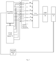
- Fig.1 is a schematic diagram showing a motor control system of an electric vehicle according to a first embodiment of the present disclosure.
- the motor control system of the electric vehicle includes an IGBT module 20, a detection module 30, a drive module 40, a channel selection module 50, a first control module 60 and a second control module 70.
- the IGBT module 20 is connected with the motor 10 of the electric vehicle.
- the detection module 30 is connected with the motor 10, and is configured to detect the motor speed.
- the drive module 40 is connected with the IGBT module 20, and is configured to drive IGBTs in the IGBT module 20 to turn on or off so as to control the motor 10 to work or stop working.
- the channel selection module 50 is connected with the drive module 40.
- the first control module 60 is connected with the channel selection module 50 and the detection module 30 respectively.
- the second control module 70 is connected with the channel selection module 50, and is communicated with the first control module 60.
- the first control module 60 communicates with the second control module 70 via a CAN (Controller Area Network) or a SCI (Serial Communication Interface).
- the first control module 60 is configured to send a first control signal to the drive module 40 so as to control the IGBT module 20.
- the first control module 60 may generate a fault signal by itself and send the fault signal to the channel selection module 50 and the second control module 70, the channel selection module 50 selects the channel of the second module 70, and the second control module 70 sends a second control signal to the drive module 40 according to the motor speed, so as to control the motor 10 to stop working.
- the motor speed is sent from the first control module 60 to the second control module 70, and when the first control module 60 has the fault, the second control module 70 sends the second control signal according to the motor speed sending from the first control module at a predetermined time T1 before the first control module 60 has the fault.
- the predetermined time T1 generally ranges from Is to 3s.
- the first control module 60 when the first control module 60 has the fault, it sends the motor speed VI detected at 1.5s before the fault occurs to the second control module 70, and the second control module 70 sends the second control signal according to V1.
- the second control module 70 is connected with the channel selection module 50 and the detection module 30 respectively.
- the second control module 70 sends the second control signal to the drive module 40 according to the current motor speed, so as to control the motor 10 to stop working.
- the current motor speed is sent from the detection module 30 to the second control module 70 in real-time.
- the first control module 60 may be a DSP (may be referred to as a main DSP).
- the main DSP may be a F28M35H52C1 chip which is a 32-bit dual core processor, has a main frequency up to 150 MHZ, and has relatively complete and powerful functions.
- the second control module 70 may also be a DSP (may be referred to as an auxiliary DSP).
- the auxiliary DSP may be a MC9S08DZ60 chip which is a 8-bit single core processor, has a main frequency of 40 MHZ and has common functions compared with the main DSP.
- the channel selection module 50 may be a channel selection chip, for example a TS3A27518E-Q1 chip which is a six-way and two-channel selector.
- the IGBT module 20 may include six IGBTs such as IGBT1, IGBT2, IGBT3, IGBT4, IGBT5 and IGBT6.
- the six IGBTs form a three-phase bridge. Each two IGBTs are connected with each other and a node is defined between them, so the IGBT module 20 has three nodes such as node A, B and C. These three nodes are connected with a three-phase of the motor 10 respectively.
- Three IGBTs such as IGBT1, IGBT3 and IGBT5 can be referred to as an upper bridge arm of the three-phase bridge.
- the other three IGBTs such as IGBT2, IGBT4 and IGBT6 can be referred to as a lower bridge arm of the three-phase bridge.
- Fig.1 and Fig.2 six outputs of the channel selection module 50 are connected with six terminals COM1, COM2, ⁇ COM6 of the drive module 40 respectively.
- Six input ports NC1, NC2, ⁇ NC6 of the first channel in the channel selection module 50 are connected with the first control module 60
- six input ports NO1, NO2, ⁇ NO6 of the second channel in the channel selection module 50 are connected with the second control module 70.
- the first control module 60 sends the first control signal (i.e.
- the PWM wave to the drive module 40 via the six input ports NCl, NC2, ⁇ NC6 of the first channel to control the six IGBTs in the IGBT module 20 to turn on or off, so as to control the motor 10 to work normally.
- the second control signal is sent to the drive module 40 via the six input ports NO1, NO2, ⁇ NO6 of the second channel of the channel selection module 50.
- the second control signal includes six signals.
- the six signals can be six first level signals, six second level signals or three first level signals and three second level signals.
- the second control module when the first control module 60 has the fault and the motor speed is less than or equal to a predetermined speed, the second control module sends six first level signals to turn off each of the six IGBTs in the IGBT module 20.
- the second control module 70 sends three first level signals and three second level signals to turn on each IGBT in the upper bridge arm or each IGBT in the lower bridge arm.
- the first level signal is a high level signal
- the second level signal is a low level signal.
- the first level signal is the low level signal
- the second level signal is the high level signal.
- the main DSP send six drive signals such as PWM wave to the drive module 40 via the channel selection module 50 such as the channel selection chip, and then the drive module 40 controls the IGBTs in the IGBT module 20 to turn on or off, so as to control the motor 10 to work normally.
- the second control module such as the auxiliary DSP sends two PWM signals according to the motor speed (i.e.
- each of the two PWM signals are divided into three signals, and finally six PWM signals are sent to the six input ports of the second channel of the channel selection module 50.
- the motor speed is also the driving speed of the vehicle, but the motor speed is the current motor speed sent from the detection module 30.
- the motor control system further includes an error detection module 80.
- the error detection module 80 is connected with the IGBT module 20 and the second control module 70 respectively, and is configured to determine whether the upper bridge arm and the lower bridge arm have an error information, to generate an error signal according to the determining result, and to send the error signal to the second control module 70.
- the error detection module 80 is configured to detect the error information such as over-current and over temperature of the IGBTs, and to send the error signal to the second control module 70 when the error formation is detected, such that the second control module 70 can take corresponding measures to protect the IGBT module 20, thus avoiding the damage to the IGBT module 20.
- the error detection module 80 may generate a first error signal and send the first error signal to the second control module 70.
- the second control module 70 can send three first level signals to turn off each IGBT in the upper bridge arm of IGBT module 20 and send three second level signals to turn on each IGBT in the lower bridge arm of the IGBT module 20.
- the error detection module 80 may generate a second error signal and send the second error signal to the second control module 70.
- the second control module 70 can send three first level signals to turn off each IGBT in the lower bridge arm of the IGBT module 20 and send three second level signals to turn on each IGBT in the upper bridge arm of the IGBT module 20. If the error detection module 80 determines that both of the upper bridge arm and the lower bridge arm have the error information, it may generate a third error signal and send the third error signal to the second control module 70. After receiving the third error signal, the second control module 70 can send six first level signals to turn off all the IGBTs in the IGBT module 20.
- the system may further include a fault detection module 90.
- the fault detection module 90 is connected with the first control module 60, the second control module 70 and the channel selection module 50 respectively, and is configured to determine whether the first control module 60 has the fault, to generate a fault signal when the first control module 60 has the fault, and to send the fault signal to the second control module 70 and the channel selection module 50.
- the channel selection module 50 can select the channel of the second control module according to the fault signal.
- the predetermined motor speed can be 6000 r/min.
- the second control module 70 i.e. the auxiliary DSP
- the channel selection module 50 can receive the fault signal sent from the fault detection module 90 and switch to the second channel from the first channel, i.e. transfer the six high level signals of the second channel to the drive module 40 to turn off each IGBT in the IGBT module 20, thus controlling the motor 10 to stop working.
- the auxiliary DSP sends out a two PWM waves according to the error information detected by the error detection module 80, in which one of the PWM waves is the high level signal, the other one is the low level signal.
- the second control module 70 controls the second channel of the channel selection module 50 to output three high level signals and three low level signals.
- the levels of the six signals output from the channel selection module 50 are differently corresponding to the IGBTs in the IGBT module 20 in different cases.
- the error detection module 80 may determine that neither the upper bridge arm nor the lower bridge arm of the three-phase bridge of the IGBT module 20 has the error information or the upper bridge arm has the error information, and send the first error signal to the auxiliary DSP, the auxiliary DSP can send three first level signals (i.e. high level signals) and three second level signals (i.e.
- the drive module 40 can drive each IGBT in the upper bridge arm of the IGBT module 20 to turn off according to the three high level signals and drive each IGBT in the lower bridge arm of the IGBT module 20 to turn on according to the three low level signals.
- the error detection module 80 may determine that the lower bridge arm of the three-phase bridge has the error information, and send the second error signal to the auxiliary DSP, the auxiliary DSP can send three high level signals and three low level signals to the drive module 40 via the channel selection module 50, such that the drive module 40 can drive each IGBT in the upper bridge arm to turn on according to the three low level signals and drive each IGBT in the lower bridge arm to turn off according to the three high level signals.
- the error detection module 80 determines that both the lower bridge arm and the upper bridge arm of the three-phase bridge have the error information, it sends the third error signal to the auxiliary DSP, the auxiliary DSP can send six high level signals to the drive module 40 via the channel selection module 50, such that the drive module can control each IGBT in the IGBT module 20 to turn off, so as to control the motor 10 to stop working.
- the system may further include a level conversion module (not shown).
- the level translation module is connected with the channel selection module 50 and the drive module 40 respectively, and is configured to convert a voltage of a drive signal sent from the channel selection module 50 into the voltage needed by the drive module 40.
- an uncontrollable failure for example, turning off waves instantaneously
- the vehicle fault for example, a crash fault of a DSP, an error of a rotary transformer, an IGBT temperature protection, a motor temperature protection
- controllable failure for example, making the current fully consumed by the motor itself, ensuring that a feedback current is a fixed value within an acceptable range, a feedback torque is small and a braking force is controlled within a few Newton meters
- FIG. 6 is a flow chart showing a controlling method for a motor control system of an electric vehicle according to a first embodiment of the present disclosure.
- the motor control system may include the IGBT module 20, the detection module 30, the drive module 40, the channel selection module 50, the first control module 60 and the second control module 70, and the first control module 60 is communicated with the second control module 70.
- the controlling method for the motor control system of the electric vehicle includes following steps.
- step S1 a motor speed is detected by the detection module 30 and the motor speed is sent to the first control module 60 from the detection module 30.
- step S2 it is determined whether the first control module 60 has the fault, if yes, execute step S3, and if no, execute step S4.
- a channel of the second control module 70 is selected by the channel selection module and then execute step S5.
- a channel of the first control module 60 is selected by the channel selection module 50, and then execute step S6.
- the second control module 70 sends a second control signal to the drive module 40 according to the motor speed sent from the first control module 60 at a predetermined time before the first control module 60 has the fault, so as to control the motor 10 to stop working.
- the first control module 60 sends a first control signal to the drive module 40 to control IGBTs in the IGBT module 20 to turn on or off, so as to control the motor 10 to work normally.
- step S1 and step S2 can be executed at the same time.
- the first control module 60 can send the first control signal (i.e. PWM wave) to the drive module 40 via the channel selection module 50 to control the IGBT module 20 to turn off or turn on, so as to control the motor 10 to work normally.
- the channel selection module 50 selects the channel of the second control module 70, i.e. selects the signal in the channel of the second control module 70 to control the motor 10.
- the second control module 70 sends the second control signal to the drive module 40 according to the motor speed sent from the first control module 60 at the predetermined time T1 before the first control module 10 has the fault, and then the drive module 40 controls the IGBT module 20, so as to control the motor 10 to stop working.
- FIG. 7 is a flow chart showing a controlling method for a motor control system of an electric vehicle according to a second embodiment of the present disclosure.
- the controlling method for the motor control system of the electric vehicle may include following steps.
- a motor speed is detected by the detection module 30 and the motor speed is sent to the first control module 60 and the second control module 70 from the detection module 30.
- step S20 it is determined whether the first control module 60 has the fault, if yes, execute step S30, if no, execute step S40.
- a channel of the second control module 70 is selected by the channel selection module 50, and then execute step S50.
- a channel of the first control module 60 is selected by the channel selection module 50, and then execute step S60.
- the second control module 70 sends a second control signal to the drive module 40 according to the current motor speed, so as to control the motor 10 to stop working.
- the first control module 60 sends a first control signal to the drive module 40, so as to control the motor 10 to work normally.
- step S10 and step S20 can be executed at the same time.
- the first control module 60 can send the first control signal (i.e. PWM wave) to the drive module 40 via the channel selection module 50 to control the IGBT module 20 to turn off or turn on, so as to control the motor 10 to work normally.
- the channel selection module 50 selects the channel of the second control module 70, i.e. select the signal in the channel of the second control module 70 to control the motor 10.
- the second control module 70 sends the second control signal to the drive module 40 according to the current motor speed sent from the detection module 30, and then the drive module controls the IGBT module 20, so as to control the motor 10 to stop working.
- Fig.8 is a flow chart showing a controlling method for a motor control system of an electric vehicle according to a third embodiment of the present disclosure.
- the second control signal includes six signals, each of which may be a first level signal or a second level signal.
- step S6 or step S60 may include following steps.
- step S41 it is determined whether the first control module 60 has the fault and whether the motor speed is less than or equal to a predetermined speed, if yes, execute step S42, if no, execute step S43.
- the second control module 70 sends six first level signals to the drive module 40, and then the drive module 40 drives each IGBT in the IGBT module to turn off.
- the second control module 70 sends three first level signals and three second level signals to the drive module 40, and then the drive module 40 drive each IGBT in the upper bridge arm to turn on or drive each IGBT in the lower bridge arm to turn on.
- the three-phase bridge of the IGBT module includes an upper bridge arm and a lower bridge arm, and the system further includes an error detection module.
- the error information in the upper bridge arm and the lower bridge arm of the three-phase bridge of the IGBT module 20 is detected to generate an error signal, and then the error signal is sent to the second control module 70.
- the error signal may be a first error signal, a second error signal or a third error signal.
- Fig. 9 is a flow chart showing a controlling method for a motor control system of an electric vehicle according to a fourth embodiment of the present disclosure. Referring to Fig. 9 , step S43 may include following steps.
- step S431 it is determined whether the upper bridge arm and the lower bridge arm of the three-phase bridge of the IGBT module 20 have the error information.
- step S432 if neither the upper bridge arm nor the lower bridge arm has the error information or if the upper bridge arm has the error information, i.e. if a first condition occurs, the first error signal is generated by the error detection module 80 and sent to the second control module 70, and the second control module 70 sends three first level signals and three second level signals according to the first error signal to turn off the upper bridge arm and to turn on the lower bridge arm.
- the second error signal is generated by the error detection module 80 and sent to the second control module 70, and the second control module 70 sends three first level signals and three second level signals according to the second error signal to turn off the lower bridge arm and to turn on the upper bridge arm.
- step S434 if both the upper bridge arm and the lower bridge arm have the error information, i.e. a third condition occurs, the third error signal is generated by the error detection module 80 and sent to the second control module 70 , and the second control module 70 sends six first level signals to turn off the each IGBT in the IGBT module 20.
- Fig. 10 is a flow chart showing a controlling method for a motor control system of an electric vehicle according to a fifth embodiment of the present disclosure. Referring to Fig.10 , the controlling method for the motor control system of the electric vehicle includes following steps.
- step S401 a motor speed is detected and it is determined whether the main DSP has the crash fault, if yes, execute step S403, if no, execute step S402.
- the channel selection chip selects a drive signal sent from the main DSP and sends the drive signal to the drive module.
- the main DSP sends the drive signal which is a six-way PWM wave to the drive module via the channel selection chip, and then the drive module controls the IGBT module to turn on or to turn off, so as to control the motor to work normally.
- the channel selection chip selects the drive signal sent from the auxiliary DSP and sends the drive signal to the drive module 40.
- the auxiliary DSP sends the drive signal which is a two-way PWM wave and processes this two-way PWM wave according the motor speed, and then the two-way PWM wave are converted into six signals to be sent to the six input ports NO1, NO2, ⁇ NO6 of the second channel of the channel selection chip respectively.
- step S404 it is determined whether the motor speed is larger than the predetermined speed, if yes, execute step S406, and if no, execute step S405.
- the motor speed can be the current motor speed sent from the detection module 30, or the motor speed sent from the first control module at the predetermined time T1 before the main DSP has the fault.
- each IGBT in the IGBT module 20 is turned off according to the drive signal.
- the predetermined motor speed can be 6000 r/min
- the auxiliary DSP sends out two PWM waves which are high level signals.
- the auxiliary DSP controls the levels of the six signals output from the second channel of the channel selection module to be high.
- the channel selection module can receive the fault signal sent from the fault detection module and switch to the second channel from the first channel, i.e. transfer the six high level signals of the second channel to the drive module to turn off each IGBT in the IGBT module, thus controlling the motor to stop working.
- step S406 it is determined whether the IGBT module has the error information, i.e. it is determined whether the upper bridge and the lower bridge arm of the IGBT module have the error information.
- the auxiliary DSP sends out two PWM waves according to the error information detected by the error detection module.
- execute step S407 when neither the upper bridge arm nor the lower bridge arm has the error information or when the upper bridge arm has the error information, i.e. when the first condition occurs, execute step S407; when the lower bridge arm has the error information, i.e. when the second condition occurs, execute step S408; when both the upper bridge arm and the lower bridge arm of the IGBT module have the error information, i.e. when the third condition occurs, execute step S405.
- each IGBT in the lower bridge arm of the IGBT module is turned off.
- the auxiliary DSP sends the high level signal to the upper bridge arm of the IGBT module 20 and sends the low level signal to the lower bridge arm of the IGBT module 20.
- the auxiliary DSP sends the high level signal and the low level signal to the drive module via the channel selection chip to turn off the upper bridge arm of the IGBT module 20 and to turn on the lower bridge arm of the IGBT module 20, so as to control the electric vehicle to stop working smoothly and steadily.
- each IGBT in the upper bridge arm of the IGBT module 20 is turned on.
- the auxiliary DSP sends the high level signal to the lower bridge arm of the IGBT module 20 and the low level signal to the upper bridge arm of the IGBT module 20.
- the auxiliary DSP sends the high level signal and the low level signal to the drive module 40 via the channel selection chip to turn off the lower bridge arm of the IGBT module 20 and to turn on the upper bridge arm of the IGBT module 20, so as to control the electric vehicle to stop working smoothly and steadily.
- an uncontrollable failure for example, turning off waves instantaneously
- the vehicle fault for example, a crash fault of a DSP, an error of a rotary transformer, an IGBT temperature protection, a motor temperature protection
- controllable failure for example, making the current fully consumed by the motor itself, ensuring that a feedback current is a fixed value within an acceptable range, a feedback torque is small and a braking force is controlled within a few Newton meters
- Fig. 11 is a schematic diagram showing an electric vehicle according to an embodiment of the present disclosure.
- the electric vehicle 601 includes the aforementioned motor control system 602.
- an uncontrollable failure for example, turning off waves instantaneously
- the vehicle fault for example, a crash fault of a DSP, an error of a rotary transformer, an IGBT temperature protection, a motor temperature protection
- controllable failure for example, making the current fully consumed by the motor itself, ensuring that a feedback current is a fixed value within an acceptable range, a feedback torque is small and a braking force is controlled within a few Newton meters
- the flow chart or any process or method described herein in other manners may represent a module, segment, or portion of code that includes one or more executable instructions to implement the specified logic function(s) or that includes one or more executable instructions of the steps of the progress.
- the flow chart shows a specific order of execution, it is understood that order of execution may differ from that which is depicted. For example, the order of execution of two or more boxes may be scrambled relative to the order shown. Also, two or more boxes shown in succession in the flow chart may be executed concurrently or with particular concurrence.
- any number of counters, state variables, warning semaphores, or messages might be added to the logical flow described herein, for purpose of enhanced utility, accounting, performance measurement, or providing troubleshooting aids, etc. It is understood that all such variations are within the scope of the present disclosure. Also, the flow chart is relatively self-explanatory and is understood by those skilled in the art to the extent that software and/or hardware can be created by one with ordinary skill in the art to carry out the various logical functions as described herein.
- a scheduling list of an executable instruction to implement the specified logic function(s) it can be embodied in any computer-readable medium for use by or in connection with an instruction execution system such as, for example, a processor in a computer system or other system.
- the logic may include, for example, statements including instructions and declarations that can be fetched from the computer-readable medium and executed by the instruction execution system.
- a "computer-readable medium" can be any medium that can contain, store, communicate, propagate, or transport the program for the instruction execution system, apparatus, device, or the device for use by in connection with the instruction execution system, apparatus, device.
- the computer readable medium can include any one of many physical media such as, for example, electronic, magnetic, optical, electromagnetic, infrared, or semiconductor media. More specific examples of a suitable computer-readable medium would include, but are not limited to, magnetic tapes, magnetic floppy diskettes, magnetic hard drives, or compact discs. Also, the computer-readable medium may be a random access memory (RAM) including, for example, static random access memory (SRAM) and dynamic random access memory (DRAM), or magnetic random access memory (MRAM).
- RAM random access memory
- SRAM static random access memory
- DRAM dynamic random access memory
- MRAM magnetic random access memory
- the computer-readable medium may be a read-only memory (ROM), a programmable read-only memory (PROM), an erasable programmable read-only memory (EPROM), an electrically erasable programmable read-only memory (EEPROM), or other type of memory device.
- ROM read-only memory
- PROM programmable read-only memory
- EPROM erasable programmable read-only memory
- EEPROM electrically erasable programmable read-only memory
- the computer-readable medium could even be paper or another suitable medium upon which the program is printed, for example, by the paper or other medium for optical scanning, and then edit, interpretation or in other suitable way for processing when necessary to obtain the program, and then stored in a computer memory.
- the device, system, and method of the present disclosure is embodied in software or code executed by general purpose hardware as discussed above, as an alternative the device, system, and method may also be embodied in dedicated hardware or a combination of software/general purpose hardware and dedicated hardware. If embodied in dedicated hardware, the device or system can be implemented as a circuit or state machine that employs any one of or a combination of a number of technologies. These technologies may include, but are not limited to, discrete logic circuits having logic gates for implementing various logic functions upon an application of one or more data signals, application specific integrated circuits having appropriate logic gates, programmable gate arrays (PGA), field programmable gate arrays (FPGA), or other components, etc.
- PGA programmable gate arrays
- FPGA field programmable gate arrays
- each functional unit in the present disclosure may be integrated in one progressing module, or each functional unit exists as an independent unit, or two or more functional units may be integrated in one module.
- the integrated module can be embodied in hardware, or software. If the integrated module is embodied in software and sold or used as an independent product, it can be stored in the computer readable storage medium.
- the computer readable storage medium may be, but not limited to read-only memories magnetic disks, or optical disks.
Landscapes
- Engineering & Computer Science (AREA)
- Power Engineering (AREA)
- Transportation (AREA)
- Mechanical Engineering (AREA)
- Life Sciences & Earth Sciences (AREA)
- Sustainable Development (AREA)
- Sustainable Energy (AREA)
- Control Of Ac Motors In General (AREA)
- Inverter Devices (AREA)
- Electric Propulsion And Braking For Vehicles (AREA)
- Control Of Electric Motors In General (AREA)
Description
- This application claims priority to and benefits of Chinese Patent Application Serial No.
201310286916.3 - The present disclosure relates to an electric vehicle technology, and in particular, relates to a motor control system of the electric vehicle and a controlling method for the motor control system of the electric vehicle and the electric vehicle.
- A drive motor controller of an electric vehicle mainly includes a power supply module, a minimum module, a rotary transformer circuit, a drive module, a power module, an IPM (intelligent power module), a sampling module and an input/output switch module etc. The power supply module can provide voltage to each module of the controller for working normally. For example, the minimum module is provided with 3.3V, 1.9V or 5V voltage to work normally, the rotary transformer circuit is provided with +5V or ± 15V voltage to work normally, the drive modules is provided with +15V, -8V or +5V voltage to work normally, the power module is provided with 460V high-voltage to work normally, the intelligent power module is provided with +12V or +5V voltage to work normally, the sampling module is provided with +5V, +3.3V, +3.3VA, +5V or +12V voltage to work normally, the input/output switch module is provided with +5V, +3.3V or +12V voltage to work normally. The minimum module mainly includes a DSP (Digital Signal Processor), a flash memory, a watchdog, an EEPROM (Electrically Erasable Programmable Read-Only Memory), a crystal oscillator, a burning mouth, etc. The rotary transformer circuit is configured to sample a current position of a motor rotor in real-time. The PWM (Pulse Width Modulation) wave output from the DSP is transferred to the drive chip after level conversion, filtering and phase inversion, so as to drive the power module. The power module (i.e., IGBT (Insulated Gate Bipolar Transistor) module) is a power component of the controller, and the motor is controlled to work or to stop working by controlling IGBTs in the power module to turn on or off. The IPM is used to realize an over-temperature protection and an over-current protection of the IGBT module, and can latch a fault signal and send the fault signal to the DSP. The sampling module is mainly used to realize a throttle sampling, a brake sampling, a motor temperature sampling, a radiator temperature sampling, a high voltage sampling, a battery voltage sampling, a three-phase current sampling, a humidity sampling and a body inclination angle sampling, etc. The input/output switch module includes a handbrake sampling, a footbrake sampling, a high voltage interlock sampling, a power-off protection and a collision signal sampling, etc.
- In the related art, the drive motor controller generally works as follows: when a crash signal of the DSP is detected, the controller directly turns off all the PWM waves of the drive signal, so as to turn off all the IGBTs in the power module, regardless of a motor speed (a driving speed of a vehicle). In this case, a counter electromotive force of the motor is higher than a voltage across a battery, and thus the energy of the motor at a high rotating speed (represented as the counter electromotive force of the motor) can be charged to the battery instantaneously via a uncontrollable rectifier of the drive motor controller. The uncontrollable rectifier instantaneously charges the battery and a bus capacitor, and due to a large current of the uncontrollable rectifier, the battery and the bus capacitor may be damaged. Moreover, since the counter electromotive force of the motor is too large, the drive components and the power components of the drive motor controller may be damaged. Furthermore, since the motor has a great feedback torque, an uncontrollable and large braking force is generated, which results in that the motor shakes intensely and makes the vehicle in an uncontrollable state.
- The existing technology has following disadvantages. When the DSP is in a crash state, the PWM wave of the drive signal sent out from the drive motor controller is in an unknown state, and if the vehicle is now in a high-speed driving state, the vehicle may have an intense back and forth shaking and get out of control, and even the drive components or the power components may be damaged.
- For example document
US 5 304 912 A discloses a control apparatus for an induction motor, wherein a V/F control circuit or a vector control circuit can be selected for supplying control signals to an inverter via a switching circuit. This vector control circuit is not connected with the V/F control circuit, such that the V/F control circuit can not communicate with the vector control circuit. A rotational speed sensor is connected with the vector control circuit. However, this rotational speed sensor is disconnected from the V/F control circuit and can not communicate with the V/F control circuit. When the switching circuit selects the V/F control circuit for supplying the control signal to the inverter, the V/F control circuit can not obtain a current motor speed or a motor speed at a predetermined time before the vector control circuit has a fault, since the V/F control circuit can neither communicate with the vector control circuit nor with the rotational speed sensor. - Document
US 2013/082762 A1 provides for example a power switch series circuit and its control method. The power switch series circuit includes a plurality of series modules, a control module and a drive module. At least one series module has a power switch and a detection module, and the detection module includes a detection unit and an isolation unit, so as to detect the overvoltage and output a voltage detection signal based on the detected voltage. The control module receives the voltage detection signal and outputs the corresponding control signal. The drive module amplifies the control signal to drive each power switch to turn ON or turn OFF. The control module outputs the corresponding control signal to turn off each power switch when the overvoltage happens. - The purpose of the present disclosure is to solve at least one of the problems existing in the prior art to at least some extent.
- Therefore, a first object of the present disclosure is to provide a motor control system of an electric vehicle, which can convert an uncontrollable failure due to the vehicle fault during a high speed driving into a controllable failure, and avoid the case that the vehicle has an intense back and forth shaking caused by the uncontrollable failure of the vehicle, and ensure that the vehicle stops more smoothly, securely and reliably from the high-speed driving state.
- A second object of the present disclosure is to provide a controlling method for the motor control system of the electric vehicle.
- A third object of the present disclosure is to provide the electric vehicle.
- According to the present invention, the motor control system of the electric vehicle is provided. The motor control system of the electric vehicle includes: an IGBT module, connected with a motor of the electric vehicle; a detection module, connected with the motor, and configured to detect a motor speed; a drive module, connected with the IGBT module, and configured to drive IGBTs in the IGBT module to turn on or off so as to control the motor to work or stop working; a first control module connected with the detection module; a second control module communicated with the first control module; and a channel selection module, connected with the drive module, the first control module and the second control module respectively, and configured to select a channel of the first control module or the second control module, in which when the first control module has a fault, the channel selection module selects the channel of the second control module; when the channel selection module selects the channel of the first control module, and to the second control module sends a first control signal to the drive module so as to control the drive module to drive the IGBTs in the IGBT module to turn on or off; and when the channel selection module selects the channel of the second control module, to the second control module sends a second control signal to the drive module according to the motor speed at a predetermined time before the first control module has the fault, so as to control the motor to stop working.
- With the motor control system of the electric vehicle according to the present invention, when the first control module has the fault, the channel selection module selects the channel of the second control module, and then the second control module sends the second control signal according to the motor speed to control the motor to stop working, which can convert an uncontrollable failure (for example, turning off waves instantaneously) due to the vehicle fault (for example, a crash fault of a DSP, an error of a rotary transformer, an IGBT temperature protection, a motor temperature protection) during a high speed driving into controllable failure (for example, making the current fully consumed by the motor itself, ensuring that a feedback current is a fixed value within an acceptable range, a feedback torque is small and a braking force is controlled within a few Newton meters), thus ensuring that the vehicle stops more smoothly, securely and reliably from the high-speed driving state, and avoiding that the vehicle has an intense forth and back shaking and power components of the vehicle are damaged.
- According to the present invention, an electric vehicle is provided. The electric vehicle includes the motor control system according to the present invention.
- With the electric vehicle according to the present invention, when the first control module has the fault, the channel selection module selects the channel of the second control module, and then the second control module sends the second control signal according to the motor speed to control the motor to stop working, which can convert an uncontrollable failure due to the vehicle fault during a high speed driving into controllable failure, thus ensuring that the vehicle stops more smoothly, securely and reliably from the high-speed driving state, and avoiding that the vehicle has an intense forth and back shaking and power components of the vehicle are damaged.
- According to the present invention, a controlling method for the motor control system of the electric vehicle is provided. The motor control system includes an IGBT module, a detection module connected with a motor of the electric vehicle, a drive module connected with the IGBT module, a channel selection module connected with the drive module, a first control module connected with the detection module and the channel selection module respectively, and a second control module connected with the channel selection module and communicated with the first control module. The controlling method for the motor control system of the electric vehicle includes: detecting a motor speed by the detection module and sending the motor speed to the first control module; determining whether the first control module has a fault; when the first control module does not have a fault, selecting a channel of the first control module by the channel selection module, and sending a first control signal by the first control module to control the drive module to drive IGBTs in the IGBT module to turn on or off so as control the motor to work or stop working; when the first control module has a fault, selecting a channel of the second control module by the channel selection module, and sending a second control signal by the second control module to the drive module according to the motor speed at a predetermined time before the first control module has the fault, so as to control the motor to stop working.
- With the controlling method according to the present invention, when the first control module has the fault, the channel selection module selects the channel of the second control module, and then the second control module sends out the second control signal according to the motor speed to control the motor to stop working, which can convert an uncontrollable failure due to the vehicle fault during a high speed driving into controllable failure, thus ensuring that the vehicle stops more smoothly, securely and reliably from the high-speed driving state, and avoiding that the vehicle has an intense forth and back shaking and power components of the vehicle are damaged.
- These and other aspects and advantages of embodiments of the present disclosure will become apparent and more readily appreciated from the following descriptions made with reference to the accompanying drawings, in which:
-
FIG. 1 is a schematic diagram showing a motor control system of an electric vehicle according to a first embodiment of the present disclosure; -
FIG. 2 is a schematic diagram showing a motor control system of an electric vehicle according to a second embodiment of the present disclosure; -
FIG. 3 is a schematic diagram showing an IGBT module connected with a motor according to an embodiment of the present disclosure; -
FIG. 4 is a schematic diagram showing a motor control system of an electric vehicle according to a third embodiment of the present disclosure; -
FIG. 5 is a schematic diagram showing a motor control system of an electric vehicle according to a fourth embodiment of the present disclosure; -
FIG. 6 is a flow chart showing a controlling method for a motor control system of an electric vehicle according to a first embodiment of the present disclosure; -
FIG. 7 is a flow chart showing a controlling method for a motor control system of an electric vehicle according to a second embodiment of the present disclosure; -
FIG. 8 is a flow chart showing a controlling method for a motor control system of an electric vehicle according to a third embodiment of the present disclosure; -
FIG. 9 is a flow chart showing a controlling method for a motor control system of an electric vehicle according to a fourth embodiment of the present disclosure; -
FIG. 10 is a flow chart showing a controlling method for a motor control system of an electric vehicle according to a fifth embodiment of the present disclosure; and -
FIG. 11 is a schematic diagram showing an electric vehicle according to an embodiment of the present disclosure. - Reference will be made in detail to embodiments of the present disclosure. The embodiments described herein with reference to drawings are explanatory, illustrative, and used to generally understand the present disclosure. The embodiments shall not be construed to limit the present disclosure. The same or similar elements and the elements having same or similar functions are denoted by like reference numerals throughout the descriptions.
- Various embodiments and examples are provided in the following description to implement different structures of the present disclosure. In order to simplify the present disclosure, certain elements and settings will be descried. However, these elements and settings are only by way of example and are not intended to limit the present disclosure. In addition, reference numerals may be repeated in different examples in the present disclosure. This repeating is for the purpose of simplification and clarity, and does not refer to relations between different embodiments and/or settings. Furthermore, examples of different processes and materials are provided in the present disclosure. However, it would be appreciated by those skilled in the art that other processes and/or materials may be also applied. Moreover, a structure in which a first feature is "on" a second feature may include an embodiment in which the first feature directly contacts the second feature, and may include an embodiment in which an additional feature is formed between the first feature and the second feature so that the first feature does not directly contact the second feature.
- Terms concerning attachments, coupling and the like, such as "connected", refer to a relationship in which structures are secured or attached to one another either directly or indirectly through intervening structures, as well as both movable or rigid attachments or relationships, unless expressly described otherwise. Unless specified or limited otherwise, the terms "connected" and variations thereof are used broadly and encompass both direct and indirect mountings, connections, supports, and couplings. Further, "connected" are not restricted to physical or mechanical connections.
- The embodiments of the present disclosure will be described in detail hereinafter with reference to the accompanying drawings, in which preferred embodiments of the disclosure are shown. This disclosure may, however, be embodied in many different forms and should not be construed as limited to the embodiments set forth herein; rather, these embodiments are provided so that this disclosure will be thorough and complete, and will fully convey the scope of the disclosure to those skilled in the art.
- A motor control system of an electric vehicle and a controlling method for the motor control system according to embodiments of the present disclosure will be described below with reference to drawings.
-
Fig.1 is a schematic diagram showing a motor control system of an electric vehicle according to a first embodiment of the present disclosure. Referring toFig.1 , the motor control system of the electric vehicle includes anIGBT module 20, adetection module 30, adrive module 40, achannel selection module 50, afirst control module 60 and asecond control module 70. - The
IGBT module 20 is connected with themotor 10 of the electric vehicle. Thedetection module 30 is connected with themotor 10, and is configured to detect the motor speed. Thedrive module 40 is connected with theIGBT module 20, and is configured to drive IGBTs in theIGBT module 20 to turn on or off so as to control themotor 10 to work or stop working. Thechannel selection module 50 is connected with thedrive module 40. Thefirst control module 60 is connected with thechannel selection module 50 and thedetection module 30 respectively. Thesecond control module 70 is connected with thechannel selection module 50, and is communicated with thefirst control module 60. For example, thefirst control module 60 communicates with thesecond control module 70 via a CAN (Controller Area Network) or a SCI (Serial Communication Interface). Thefirst control module 60 is configured to send a first control signal to thedrive module 40 so as to control theIGBT module 20. When thefirst control module 60 has a fault, thefirst control module 60 may generate a fault signal by itself and send the fault signal to thechannel selection module 50 and thesecond control module 70, thechannel selection module 50 selects the channel of thesecond module 70, and thesecond control module 70 sends a second control signal to thedrive module 40 according to the motor speed, so as to control themotor 10 to stop working. In this embodiment, the motor speed is sent from thefirst control module 60 to thesecond control module 70, and when thefirst control module 60 has the fault, thesecond control module 70 sends the second control signal according to the motor speed sending from the first control module at a predetermined time T1 before thefirst control module 60 has the fault. The predetermined time T1 generally ranges from Is to 3s. For example, when thefirst control module 60 has the fault, it sends the motor speed VI detected at 1.5s before the fault occurs to thesecond control module 70, and thesecond control module 70 sends the second control signal according to V1. - In another embodiment of the present disclosure, as shown in
Fig.2 , thesecond control module 70 is connected with thechannel selection module 50 and thedetection module 30 respectively. When thefirst control module 60 has the fault and thechannel selection module 50 selects the channel of thesecond control module 70, thesecond control module 70 sends the second control signal to thedrive module 40 according to the current motor speed, so as to control themotor 10 to stop working. The current motor speed is sent from thedetection module 30 to thesecond control module 70 in real-time. - In one embodiment of the present disclosure, the
first control module 60 may be a DSP (may be referred to as a main DSP). The main DSP may be a F28M35H52C1 chip which is a 32-bit dual core processor, has a main frequency up to 150 MHZ, and has relatively complete and powerful functions. Thesecond control module 70 may also be a DSP (may be referred to as an auxiliary DSP). The auxiliary DSP may be a MC9S08DZ60 chip which is a 8-bit single core processor, has a main frequency of 40 MHZ and has common functions compared with the main DSP. Thechannel selection module 50 may be a channel selection chip, for example a TS3A27518E-Q1 chip which is a six-way and two-channel selector. - Referring to
Fig.3 , theIGBT module 20 may include six IGBTs such as IGBT1, IGBT2, IGBT3, IGBT4, IGBT5 and IGBT6. The six IGBTs form a three-phase bridge. Each two IGBTs are connected with each other and a node is defined between them, so theIGBT module 20 has three nodes such as node A, B and C. These three nodes are connected with a three-phase of themotor 10 respectively. Three IGBTs such as IGBT1, IGBT3 and IGBT5 can be referred to as an upper bridge arm of the three-phase bridge. The other three IGBTs such as IGBT2, IGBT4 and IGBT6 can be referred to as a lower bridge arm of the three-phase bridge. Referring toFig.1 andFig.2 , six outputs of thechannel selection module 50 are connected with six terminals COM1, COM2,···COM6 of thedrive module 40 respectively. Six input ports NC1, NC2, ···NC6 of the first channel in thechannel selection module 50 are connected with thefirst control module 60, and six input ports NO1, NO2, ···NO6 of the second channel in thechannel selection module 50 are connected with thesecond control module 70. In normal case, thefirst control module 60 sends the first control signal (i.e. PWM wave) to thedrive module 40 via the six input ports NCl, NC2, ··· NC6 of the first channel to control the six IGBTs in theIGBT module 20 to turn on or off, so as to control themotor 10 to work normally. When thefirst control module 60 has the fault, the second control signal is sent to thedrive module 40 via the six input ports NO1, NO2, ···NO6 of the second channel of thechannel selection module 50. - In one embodiment of the present disclosure, the second control signal includes six signals. The six signals can be six first level signals, six second level signals or three first level signals and three second level signals.
- Referring to
Fig.1 , when thefirst control module 60 has the fault and the motor speed is less than or equal to a predetermined speed, the second control module sends six first level signals to turn off each of the six IGBTs in theIGBT module 20. When thefirst control module 60 has the fault and the motor speed is larger than the predetermined speed, thesecond control module 70 sends three first level signals and three second level signals to turn on each IGBT in the upper bridge arm or each IGBT in the lower bridge arm. In one embodiment, the first level signal is a high level signal, and the second level signal is a low level signal. In another embodiment, the first level signal is the low level signal, and the second level signal is the high level signal. In other words, in normal case, i.e., when the first control module 60 (i.e. the main DSP) has no fault, the main DSP send six drive signals such as PWM wave to thedrive module 40 via thechannel selection module 50 such as the channel selection chip, and then thedrive module 40 controls the IGBTs in theIGBT module 20 to turn on or off, so as to control themotor 10 to work normally. When the main DSP has the fault, the second control module such as the auxiliary DSP sends two PWM signals according to the motor speed (i.e. the driving speed of the vehicle) sent from thefirst control module 60 at the predetermined time before thefirst control module 60 has the fault, and then each of the two PWM signals are divided into three signals, and finally six PWM signals are sent to the six input ports of the second channel of thechannel selection module 50. - In another embodiment of the present disclosure, referring to
Fig.2 , the motor speed is also the driving speed of the vehicle, but the motor speed is the current motor speed sent from thedetection module 30. - Referring to
Fig.4 andFig.5 , the motor control system further includes anerror detection module 80. Theerror detection module 80 is connected with theIGBT module 20 and thesecond control module 70 respectively, and is configured to determine whether the upper bridge arm and the lower bridge arm have an error information, to generate an error signal according to the determining result, and to send the error signal to thesecond control module 70. In other words, theerror detection module 80 is configured to detect the error information such as over-current and over temperature of the IGBTs, and to send the error signal to thesecond control module 70 when the error formation is detected, such that thesecond control module 70 can take corresponding measures to protect theIGBT module 20, thus avoiding the damage to theIGBT module 20. - Further, if the
error detection module 80 determines that neither the upper bridge arm nor the lower bridge arm has the error information or only the upper bridge arm has the error information, it may generate a first error signal and send the first error signal to thesecond control module 70. After receiving the first error signal, thesecond control module 70 can send three first level signals to turn off each IGBT in the upper bridge arm ofIGBT module 20 and send three second level signals to turn on each IGBT in the lower bridge arm of theIGBT module 20. If theerror detection module 80 determines that only the lower bridge arm has the error information, it may generate a second error signal and send the second error signal to thesecond control module 70. After receiving the second error signal, thesecond control module 70 can send three first level signals to turn off each IGBT in the lower bridge arm of theIGBT module 20 and send three second level signals to turn on each IGBT in the upper bridge arm of theIGBT module 20. If theerror detection module 80 determines that both of the upper bridge arm and the lower bridge arm have the error information, it may generate a third error signal and send the third error signal to thesecond control module 70. After receiving the third error signal, thesecond control module 70 can send six first level signals to turn off all the IGBTs in theIGBT module 20. - When the
first control module 60 has the fault, thefirst control module 60 can send the fault signal by itself to thesecond control module 70 and thechannel selection module 50, and can also be detected by an additional detection module which sends the fault signal when detecting the fault. Referring toFig.4 andFig.5 , in some embodiments of the present disclosure, the system may further include afault detection module 90. Thefault detection module 90 is connected with thefirst control module 60, thesecond control module 70 and thechannel selection module 50 respectively, and is configured to determine whether thefirst control module 60 has the fault, to generate a fault signal when thefirst control module 60 has the fault, and to send the fault signal to thesecond control module 70 and thechannel selection module 50. Thus, thechannel selection module 50 can select the channel of the second control module according to the fault signal. - In one embodiment of the present disclosure, the predetermined motor speed can be 6000 r/min. When the motor speed is less than or equal to the predetermined motor speed, the second control module 70 (i.e. the auxiliary DSP) sends out two PWM waves which are high level signals. In other words, the
second control module 70 controls the levels of the six signals output from the second channel of thechannel selection module 50 to be high. Once the main DSP has a crash fault at this time, thechannel selection module 50 can receive the fault signal sent from thefault detection module 90 and switch to the second channel from the first channel, i.e. transfer the six high level signals of the second channel to thedrive module 40 to turn off each IGBT in theIGBT module 20, thus controlling themotor 10 to stop working. When the motor speed is larger than the predetermined motor speed, the auxiliary DSP sends out a two PWM waves according to the error information detected by theerror detection module 80, in which one of the PWM waves is the high level signal, the other one is the low level signal. In other words, thesecond control module 70 controls the second channel of thechannel selection module 50 to output three high level signals and three low level signals. - Specifically, according to the different error signals sent from the
error detection module 80, the levels of the six signals output from thechannel selection module 50 are differently corresponding to the IGBTs in theIGBT module 20 in different cases. When the main DSP occurs the crash fault, theerror detection module 80 may determine that neither the upper bridge arm nor the lower bridge arm of the three-phase bridge of theIGBT module 20 has the error information or the upper bridge arm has the error information, and send the first error signal to the auxiliary DSP, the auxiliary DSP can send three first level signals (i.e. high level signals) and three second level signals (i.e. low level signals) to thedrive module 40 via thechannel selection module 50, such that thedrive module 40 can drive each IGBT in the upper bridge arm of theIGBT module 20 to turn off according to the three high level signals and drive each IGBT in the lower bridge arm of theIGBT module 20 to turn on according to the three low level signals. When the main DSP occurs the crash fault, theerror detection module 80 may determine that the lower bridge arm of the three-phase bridge has the error information, and send the second error signal to the auxiliary DSP, the auxiliary DSP can send three high level signals and three low level signals to thedrive module 40 via thechannel selection module 50, such that thedrive module 40 can drive each IGBT in the upper bridge arm to turn on according to the three low level signals and drive each IGBT in the lower bridge arm to turn off according to the three high level signals. When theerror detection module 80 ay determines that both the lower bridge arm and the upper bridge arm of the three-phase bridge have the error information, it sends the third error signal to the auxiliary DSP, the auxiliary DSP can send six high level signals to thedrive module 40 via thechannel selection module 50, such that the drive module can control each IGBT in theIGBT module 20 to turn off, so as to control themotor 10 to stop working. - Referring to
Fig.4 andFig.5 , the system may further include a level conversion module (not shown). The level translation module is connected with thechannel selection module 50 and thedrive module 40 respectively, and is configured to convert a voltage of a drive signal sent from thechannel selection module 50 into the voltage needed by thedrive module 40. - With the motor control system of the electric vehicle according to embodiments of the present disclosure, by adding the
second control module 70 which is selected by thechannel selection module 50 when thefirst control module 60 has the fault, and sends out different second control signals according to the motor speed to control themotor 10 to stop working, an uncontrollable failure (for example, turning off waves instantaneously) due to the vehicle fault (for example, a crash fault of a DSP, an error of a rotary transformer, an IGBT temperature protection, a motor temperature protection) during a high speed driving can be converted into controllable failure (for example, making the current fully consumed by the motor itself, ensuring that a feedback current is a fixed value within an acceptable range, a feedback torque is small and a braking force is controlled within a few Newton meters), thus ensuring that the vehicle stops more smoothly, securely and reliably from the high-speed driving state, and avoiding that the vehicle has an intense forth and back shaking and power components of the vehicle are damaged. -
FIG. 6 is a flow chart showing a controlling method for a motor control system of an electric vehicle according to a first embodiment of the present disclosure. The motor control system may include theIGBT module 20, thedetection module 30, thedrive module 40, thechannel selection module 50, thefirst control module 60 and thesecond control module 70, and thefirst control module 60 is communicated with thesecond control module 70. Referring toFig.6 , the controlling method for the motor control system of the electric vehicle includes following steps. - At step S1, a motor speed is detected by the
detection module 30 and the motor speed is sent to thefirst control module 60 from thedetection module 30. - At step S2, it is determined whether the
first control module 60 has the fault, if yes, execute step S3, and if no, execute step S4. - At step S3, a channel of the
second control module 70 is selected by the channel selection module and then execute step S5. - At step S4, a channel of the
first control module 60 is selected by thechannel selection module 50, and then execute step S6. - At step S5, the
second control module 70 sends a second control signal to thedrive module 40 according to the motor speed sent from thefirst control module 60 at a predetermined time before thefirst control module 60 has the fault, so as to control themotor 10 to stop working. - At step S6, the
first control module 60 sends a first control signal to thedrive module 40 to control IGBTs in theIGBT module 20 to turn on or off, so as to control themotor 10 to work normally. - It should be noted that, step S1 and step S2 can be executed at the same time. When the
first control module 60 has no fault, thefirst control module 60 can send the first control signal (i.e. PWM wave) to thedrive module 40 via thechannel selection module 50 to control theIGBT module 20 to turn off or turn on, so as to control themotor 10 to work normally. If thefirst control module 60 has the fault, thechannel selection module 50 selects the channel of thesecond control module 70, i.e. selects the signal in the channel of thesecond control module 70 to control themotor 10. Thesecond control module 70 sends the second control signal to thedrive module 40 according to the motor speed sent from thefirst control module 60 at the predetermined time T1 before thefirst control module 10 has the fault, and then thedrive module 40 controls theIGBT module 20, so as to control themotor 10 to stop working. -
FIG. 7 is a flow chart showing a controlling method for a motor control system of an electric vehicle according to a second embodiment of the present disclosure. Referring toFIG. 7 , the controlling method for the motor control system of the electric vehicle may include following steps. - At step S10, a motor speed is detected by the
detection module 30 and the motor speed is sent to thefirst control module 60 and thesecond control module 70 from thedetection module 30. - At step S20, it is determined whether the
first control module 60 has the fault, if yes, execute step S30, if no, execute step S40. - At step S30, a channel of the
second control module 70 is selected by thechannel selection module 50, and then execute step S50. - At step S40, a channel of the
first control module 60 is selected by thechannel selection module 50, and then execute step S60. - At step S50, the
second control module 70 sends a second control signal to thedrive module 40 according to the current motor speed, so as to control themotor 10 to stop working. - At step S60, the
first control module 60 sends a first control signal to thedrive module 40, so as to control themotor 10 to work normally. - It should be noted that, step S10 and step S20 can be executed at the same time. When the
first control module 60 has no fault, thefirst control module 60 can send the first control signal (i.e. PWM wave) to thedrive module 40 via thechannel selection module 50 to control theIGBT module 20 to turn off or turn on, so as to control themotor 10 to work normally. If thefirst control module 60 has the fault, thechannel selection module 50 selects the channel of thesecond control module 70, i.e. select the signal in the channel of thesecond control module 70 to control themotor 10. Thesecond control module 70 sends the second control signal to thedrive module 40 according to the current motor speed sent from thedetection module 30, and then the drive module controls theIGBT module 20, so as to control themotor 10 to stop working. -
Fig.8 is a flow chart showing a controlling method for a motor control system of an electric vehicle according to a third embodiment of the present disclosure. The second control signal includes six signals, each of which may be a first level signal or a second level signal. Referring toFig.8 , step S6 or step S60 may include following steps. - At step S41, it is determined whether the
first control module 60 has the fault and whether the motor speed is less than or equal to a predetermined speed, if yes, execute step S42, if no, execute step S43. - At step S42, the
second control module 70 sends six first level signals to thedrive module 40, and then thedrive module 40 drives each IGBT in the IGBT module to turn off. - At step S43, the
second control module 70 sends three first level signals and three second level signals to thedrive module 40, and then thedrive module 40 drive each IGBT in the upper bridge arm to turn on or drive each IGBT in the lower bridge arm to turn on. - Specifically, the three-phase bridge of the IGBT module includes an upper bridge arm and a lower bridge arm, and the system further includes an error detection module. When the motor speed is larger than the predetermined speed, the error information in the upper bridge arm and the lower bridge arm of the three-phase bridge of the
IGBT module 20 is detected to generate an error signal, and then the error signal is sent to thesecond control module 70. The error signal may be a first error signal, a second error signal or a third error signal.Fig. 9 is a flow chart showing a controlling method for a motor control system of an electric vehicle according to a fourth embodiment of the present disclosure. Referring toFig. 9 , step S43 may include following steps. - At step S431, it is determined whether the upper bridge arm and the lower bridge arm of the three-phase bridge of the
IGBT module 20 have the error information. - At step S432, if neither the upper bridge arm nor the lower bridge arm has the error information or if the upper bridge arm has the error information, i.e. if a first condition occurs, the first error signal is generated by the
error detection module 80 and sent to thesecond control module 70, and thesecond control module 70 sends three first level signals and three second level signals according to the first error signal to turn off the upper bridge arm and to turn on the lower bridge arm. - At step S433, if the lower bridge arm has the error information, i.e. a second condition occurs, the second error signal is generated by the
error detection module 80 and sent to thesecond control module 70, and thesecond control module 70 sends three first level signals and three second level signals according to the second error signal to turn off the lower bridge arm and to turn on the upper bridge arm. - At step S434, if both the upper bridge arm and the lower bridge arm have the error information, i.e. a third condition occurs, the third error signal is generated by the
error detection module 80 and sent to thesecond control module 70 , and thesecond control module 70 sends six first level signals to turn off the each IGBT in theIGBT module 20. -
Fig. 10 is a flow chart showing a controlling method for a motor control system of an electric vehicle according to a fifth embodiment of the present disclosure. Referring toFig.10 , the controlling method for the motor control system of the electric vehicle includes following steps. - At step S401, a motor speed is detected and it is determined whether the main DSP has the crash fault, if yes, execute step S403, if no, execute step S402.
- At step S402, the channel selection chip selects a drive signal sent from the main DSP and sends the drive signal to the drive module.
- Specifically, the main DSP sends the drive signal which is a six-way PWM wave to the drive module via the channel selection chip, and then the drive module controls the IGBT module to turn on or to turn off, so as to control the motor to work normally.
- At step S403, the channel selection chip selects the drive signal sent from the auxiliary DSP and sends the drive signal to the
drive module 40. - Specifically, the auxiliary DSP sends the drive signal which is a two-way PWM wave and processes this two-way PWM wave according the motor speed, and then the two-way PWM wave are converted into six signals to be sent to the six input ports NO1, NO2, ···NO6 of the second channel of the channel selection chip respectively.
- At step S404, it is determined whether the motor speed is larger than the predetermined speed, if yes, execute step S406, and if no, execute step S405.The motor speed can be the current motor speed sent from the
detection module 30, or the motor speed sent from the first control module at the predetermined time T1 before the main DSP has the fault. - At step S405, each IGBT in the
IGBT module 20 is turned off according to the drive signal. - Specifically, the predetermined motor speed can be 6000 r/min, when the motor speed is less than or equal to the predetermined motor speed, the auxiliary DSP sends out two PWM waves which are high level signals. In other words, the auxiliary DSP controls the levels of the six signals output from the second channel of the channel selection module to be high. Once the main DSP has the crash fault at this time, the channel selection module can receive the fault signal sent from the fault detection module and switch to the second channel from the first channel, i.e. transfer the six high level signals of the second channel to the drive module to turn off each IGBT in the IGBT module, thus controlling the motor to stop working.
- At step S406, it is determined whether the IGBT module has the error information, i.e. it is determined whether the upper bridge and the lower bridge arm of the IGBT module have the error information.
- In other words, when the motor speed is larger than 6000 r/min, the auxiliary DSP sends out two PWM waves according to the error information detected by the error detection module. When neither the upper bridge arm nor the lower bridge arm has the error information or when the upper bridge arm has the error information, i.e. when the first condition occurs, execute step S407; when the lower bridge arm has the error information, i.e. when the second condition occurs, execute step S408; when both the upper bridge arm and the lower bridge arm of the IGBT module have the error information, i.e. when the third condition occurs, execute step S405.
- At step S407, each IGBT in the lower bridge arm of the IGBT module is turned off.
- Specifically, when the main DSP has the crash fault, and the IGBT module has no error information or only the upper bridge arm has the error information, the auxiliary DSP sends the high level signal to the upper bridge arm of the
IGBT module 20 and sends the low level signal to the lower bridge arm of theIGBT module 20. Specifically, the auxiliary DSP sends the high level signal and the low level signal to the drive module via the channel selection chip to turn off the upper bridge arm of theIGBT module 20 and to turn on the lower bridge arm of theIGBT module 20, so as to control the electric vehicle to stop working smoothly and steadily. - At step S408, each IGBT in the upper bridge arm of the
IGBT module 20 is turned on. - Specifically, when the main DSP has the crash fault, and the lower bridge arm has the error information, the auxiliary DSP sends the high level signal to the lower bridge arm of the
IGBT module 20 and the low level signal to the upper bridge arm of theIGBT module 20. Specifically, the auxiliary DSP sends the high level signal and the low level signal to thedrive module 40 via the channel selection chip to turn off the lower bridge arm of theIGBT module 20 and to turn on the upper bridge arm of theIGBT module 20, so as to control the electric vehicle to stop working smoothly and steadily. - With the controlling method for the motor control system of the electric vehicle according to embodiments of the present disclosure, by adding the
second control module 70 which is selected by thechannel selection module 50 when thefirst control module 60 has the fault, and sends out different second control signals according to the motor speed to control themotor 10 to stop working, an uncontrollable failure (for example, turning off waves instantaneously) due to the vehicle fault (for example, a crash fault of a DSP, an error of a rotary transformer, an IGBT temperature protection, a motor temperature protection) during a high speed driving can be converted into controllable failure (for example, making the current fully consumed by the motor itself, ensuring that a feedback current is a fixed value within an acceptable range, a feedback torque is small and a braking force is controlled within a few Newton meters), thus ensuring that the vehicle stops more smoothly, securely and reliably from the high-speed driving state, and avoiding that the vehicle has an intense forth and back shaking and power components of the vehicle are damaged. - The present disclosure also provides an
electric vehicle 601.Fig. 11 is a schematic diagram showing an electric vehicle according to an embodiment of the present disclosure. Referring toFig. 11 , theelectric vehicle 601 includes the aforementionedmotor control system 602. - With the electric vehicle according to embodiments of the present disclosure, an uncontrollable failure (for example, turning off waves instantaneously) due to the vehicle fault (for example, a crash fault of a DSP, an error of a rotary transformer, an IGBT temperature protection, a motor temperature protection) during a high speed driving can be converted into controllable failure (for example, making the current fully consumed by the motor itself, ensuring that a feedback current is a fixed value within an acceptable range, a feedback torque is small and a braking force is controlled within a few Newton meters), thus ensuring that the vehicle stops more smoothly, securely and reliably from the high-speed driving state, and avoiding that the vehicle has an intense forth and back shaking and power components of the vehicle are damaged.
- It will be understood that, the flow chart or any process or method described herein in other manners may represent a module, segment, or portion of code that includes one or more executable instructions to implement the specified logic function(s) or that includes one or more executable instructions of the steps of the progress. Although the flow chart shows a specific order of execution, it is understood that order of execution may differ from that which is depicted. For example, the order of execution of two or more boxes may be scrambled relative to the order shown. Also, two or more boxes shown in succession in the flow chart may be executed concurrently or with particular concurrence. In addition, any number of counters, state variables, warning semaphores, or messages might be added to the logical flow described herein, for purpose of enhanced utility, accounting, performance measurement, or providing troubleshooting aids, etc. It is understood that all such variations are within the scope of the present disclosure. Also, the flow chart is relatively self-explanatory and is understood by those skilled in the art to the extent that software and/or hardware can be created by one with ordinary skill in the art to carry out the various logical functions as described herein.
- The logic and step described in the flow chart or in other manners, for example, a scheduling list of an executable instruction to implement the specified logic function(s), it can be embodied in any computer-readable medium for use by or in connection with an instruction execution system such as, for example, a processor in a computer system or other system. In this sense, the logic may include, for example, statements including instructions and declarations that can be fetched from the computer-readable medium and executed by the instruction execution system. In the context of the present disclosure, a "computer-readable medium" can be any medium that can contain, store, communicate, propagate, or transport the program for the instruction execution system, apparatus, device, or the device for use by in connection with the instruction execution system, apparatus, device. The computer readable medium can include any one of many physical media such as, for example, electronic, magnetic, optical, electromagnetic, infrared, or semiconductor media. More specific examples of a suitable computer-readable medium would include, but are not limited to, magnetic tapes, magnetic floppy diskettes, magnetic hard drives, or compact discs. Also, the computer-readable medium may be a random access memory (RAM) including, for example, static random access memory (SRAM) and dynamic random access memory (DRAM), or magnetic random access memory (MRAM). In addition, the computer-readable medium may be a read-only memory (ROM), a programmable read-only memory (PROM), an erasable programmable read-only memory (EPROM), an electrically erasable programmable read-only memory (EEPROM), or other type of memory device. Further, the computer-readable medium could even be paper or another suitable medium upon which the program is printed, for example, by the paper or other medium for optical scanning, and then edit, interpretation or in other suitable way for processing when necessary to obtain the program, and then stored in a computer memory.
- Although the device, system, and method of the present disclosure is embodied in software or code executed by general purpose hardware as discussed above, as an alternative the device, system, and method may also be embodied in dedicated hardware or a combination of software/general purpose hardware and dedicated hardware. If embodied in dedicated hardware, the device or system can be implemented as a circuit or state machine that employs any one of or a combination of a number of technologies. These technologies may include, but are not limited to, discrete logic circuits having logic gates for implementing various logic functions upon an application of one or more data signals, application specific integrated circuits having appropriate logic gates, programmable gate arrays (PGA), field programmable gate arrays (FPGA), or other components, etc.
- Such technologies are generally well known by those skilled in the art and consequently, are not described in detail herein. It can be understood that all or part of the steps in the method of the above embodiments can be implemented by instructing related hardware via programs, the program may be stored in a computer readable storage medium, and the program includes one step or combinations of the steps of the method when the program is executed.
- In addition, each functional unit in the present disclosure may be integrated in one progressing module, or each functional unit exists as an independent unit, or two or more functional units may be integrated in one module. The integrated module can be embodied in hardware, or software. If the integrated module is embodied in software and sold or used as an independent product, it can be stored in the computer readable storage medium.
- The computer readable storage medium may be, but not limited to read-only memories magnetic disks, or optical disks.
- Reference throughout this specification to "an embodiment," "some embodiments," "one embodiment", "another example," "an example," "a specific example," or "some examples," means that a particular feature, structure, material, or characteristic described in connection with the embodiment or example is included in at least one embodiment or example of the present disclosure. Thus, the appearances of the phrases such as "in some embodiments," "in one embodiment", "in an embodiment", "in another example," "in an example," "in a specific example," or "in some examples," in various places throughout this specification are not necessarily referring to the same embodiment or example of the present disclosure. Furthermore, the particular features, structures, materials, or characteristics may be combined in any suitable manner in one or more embodiments or examples.
- Although explanatory embodiments have been shown and described, it would be appreciated by those skilled in the art that the above embodiments cannot be construed to limit the present disclosure, and changes, alternatives, and modifications can be made in the embodiments without departing from the scope of the present claims.
Claims (10)
- A motor control system of an electric vehicle, comprising:an IGBT module (20), connectable with a motor (10) of the electric vehicle;a detection module (30), connectable with the motor, and configured to detect a motor speed;a drive module (40), connected with the IGBT module (20), and configured to drive IGBTs in the IGBT module (20) to turn on or off so as to control the motor (10) to work or stop working;a first control module (60), connected with the detection module (30);a second control module (70); anda channel selection module (50), connected with the drive module (40), the first control module (60) and the second control module (70) respectively, and configured to select a channel of the first control module (60) or the second control module (70),wherein when the first control module (60) has a fault, the channel selection module (50) selects the channel of the second control module (70);when the channel selection module (50) selects the channel of the first control module (60), the first control module (60) sends a first control signal to the drive module (40) so as to control the drive module to drive the IGBTs in IGBT module (20) to turn on or off;characterized in thatthe second control module (70) is communicated with the first control module (60); andwhen the channel selection module (50) selects the channel of the second control module (70), the second control module (70) sends a second control signal to the drive module (40) according to the motor speed, so as to control the motor (10) to stop working, wherein the motor speed is the motor speed at a predetermined time before the first control module (60) has the fault or the current motor speed.
- The system of claim 1, wherein the second control signal comprises six signals, and the IGBT module (20) comprises six IGBTs consisting a three-phase bridge, in which the three-phase bridge comprises an upper bridge arm and a lower bridge arm.
- The system of claim 2, wherein
when the first control module (60) has the fault and the motor speed is less than or equal to a predetermined speed, the second control module (70) sends six first level signals to turn off each of the six IGBTs in the IGBT module (20); and
when the first control module (60) has the fault and the motor speed is larger than the predetermined speed, the second control module (70) sends three first level signals and three second level signals to turn on each IGBT in the upper bridge arm or each IGBT in the lower bridge arm. - The system of any one of claims 1-3, further comprising:an error detection module (80), connected with the IGBT module (20) and the second control module (70) respectively, and configured to determine whether the upper bridge arm and the lower bridge arm have an error information, to generate a first error signal if neither the upper bridge arm nor the lower bridge arm has the error information or if the upper bridge arm has the error information, to generate a second error signal if the lower bridge arm has the error information, and to generate a third error signal if each of the upper bridge arm and the lower bridge arm has the error information,wherein the second control module (70) is further configured to send three first level signals to turn off each IGBT in the upper bridge arm and send three second level signals to turn on each IGBT in the lower bridge arm according to the first error signal; to send three second level signals to turn on each IGBT in the upper bridge arm and send three first level signals to turn off each IGBT in the lower bridge arm according to the second error signal; and to send six first level signals according to the third error signal to turn off each IGBT in the IGBT module (20).
- The system of any one of claim 1-4, further comprising:
a fault detection module (90), connected with the first control module (60), the second control module (70) and the channel selection (50) module respectively, and configured to determine whether the first control module (60) has the fault, to generate a fault signal when the first control module (60) has the fault, and to send the fault signal to the second control module (70) and the channel selection module (50) respectively. - An electric vehicle (601), comprising a motor control system (602) of any one of claims 1-5.
- A controlling method for a motor control system of an electric vehicle, wherein the motor control system comprises an IGBT module (20), a detection module (30) connected with a motor (10) of the electric vehicle, a drive module (40) connected with the IGBT module (20), a channel selection module (50) connected with the drive module (40), a first control module (60) connected with the detection module (30) and the channel selection module (50) respectively, and a second control module (70) connected with the channel selection module (50), and the controlling method comprises:detecting a motor speed by the detection module (30) and sending the motor speed to the first control module (60);determining whether the first control module (60) has a fault;when the first control module (60) does not have a fault, selecting a channel of the first control module (60) by the channel selection module (50), and sending a first control signal by the first control module (60) to control the drive module (40) to drive IGBTs in the IGBT module (20) to turn on or off;characterized in thatthe second control module (70) is communicated with the first control module (60), and the controlling method further comprises:
when the first control module (60) has a fault, selecting a channel of the second control module (70) by the channel selection module (50), and sending a second control signal by the second control module (70) according to the motor speed so as to control the motor (10) to stop working, wherein the motor speed is the motor speed at a predetermined time before the first control module (60) has the fault or the current motor speed. - The method of claim 7, wherein the second control signal comprises six signals, and the IGBT module (20) comprises six IGBTs consisting a three-phase bridge, in which the three-phase bridge comprises an upper bridge arm and a lower bridge arm.
- The method of claim 8, wherein
sending a second control signal by the second control module (70) according to the motor speed so as to control the motor (10) to stop working comprises:when the first control module (60) has the fault and the motor speed is less than or equal to a predetermined speed, sending six first level signals by the second control module (70) to turn off each of the six IGBTs in the IGBT module; andwhen the first control module (60) has the fault and the motor speed is larger than the predetermined speed, sending three first level signals and three second level signals by the second control module (70) to turn on each IGBT in the upper bridge arm or each IGBT in the lower bridge arm. - The method of claim 8 or 9, further comprising:determining whether the upper bridge arm and the lower bridge arm have an error information;generating a first error signal if neither the upper bridge arm nor the lower bridge arm has the error information or if the upper bridge arm has the error information, and sending three first level signals to turn off each IGBT in the upper bridge arm and sending three second level signals to turn on each IGBT in the lower bridge arm by the second control module (70) according to the first error signal;generating a second error signal if the lower bridge arm has the error information, and sending three second level signals to turn on each IGBT in the upper bridge arm and sending three first level signals to turn off each IGBT in the lower bridge arm by the second control module (70) according to the second error signal; andgenerating a third error signal if each of the upper bridge arm and the lower bridge arm has the error information, and sending six first level signals by the second control module (70) according to the third error signal to turn off each IGBT in the IGBT module (20).
Applications Claiming Priority (2)
| Application Number | Priority Date | Filing Date | Title |
|---|---|---|---|
| CN201310286916.3A CN104283485B (en) | 2013-07-09 | 2013-07-09 | Electric automobile and its electric machine control system and control method |
| PCT/CN2014/081836 WO2015003619A1 (en) | 2013-07-09 | 2014-07-08 | Motor control system of electric vehicle and controlling method for motor control system of electric vehicle and electric vehicle |
Publications (3)
| Publication Number | Publication Date |
|---|---|
| EP3020128A1 EP3020128A1 (en) | 2016-05-18 |
| EP3020128A4 EP3020128A4 (en) | 2016-07-06 |
| EP3020128B1 true EP3020128B1 (en) | 2019-09-18 |
Family
ID=52258045
Family Applications (1)
| Application Number | Title | Priority Date | Filing Date |
|---|---|---|---|
| EP14822105.4A Active EP3020128B1 (en) | 2013-07-09 | 2014-07-08 | Motor control system of electric vehicle and controlling method for motor control system of electric vehicle and electric vehicle |
Country Status (4)
| Country | Link |
|---|---|
| US (1) | US9577569B2 (en) |
| EP (1) | EP3020128B1 (en) |
| CN (1) | CN104283485B (en) |
| WO (1) | WO2015003619A1 (en) |
Families Citing this family (30)
| Publication number | Priority date | Publication date | Assignee | Title |
|---|---|---|---|---|
| US10317861B2 (en) * | 2015-09-04 | 2019-06-11 | Asia Vital Components Co., Ltd. | Switch drive circuit capable of saving timers of fan processor |
| CN106627181A (en) * | 2015-09-10 | 2017-05-10 | 北汽福田汽车股份有限公司 | Battery management system, vehicle with same and method of controlling battery relay |
| DE102016211498A1 (en) | 2016-06-27 | 2017-12-28 | Robert Bosch Gmbh | Method and device for external monitoring of power electronics |
| CN106026826A (en) * | 2016-08-03 | 2016-10-12 | 长春工业大学 | Networked measuring and controlling method for electric vehicle drive motor working condition matching control effectiveness |
| WO2018053680A1 (en) * | 2016-09-20 | 2018-03-29 | SZ DJI Technology Co., Ltd. | Systems and methods for providing redundancy to electronic speed control systems |
| CN106452269A (en) * | 2016-12-14 | 2017-02-22 | 合肥德仁智能科技有限公司 | High-reliability alternating-current motor control device applied to electric vehicles |
| CN108803650A (en) * | 2017-04-26 | 2018-11-13 | 深圳市道通智能航空技术有限公司 | The control method and device of unmanned plane, unmanned plane |
| CN109412118B (en) * | 2017-08-17 | 2020-07-10 | 比亚迪股份有限公司 | Protection devices for motor controllers, motor controllers and electric vehicles |
| CN109910613B (en) * | 2017-12-13 | 2021-09-07 | 宝沃汽车(中国)有限公司 | Torque turn-off method, torque turn-off system and vehicle |
| CN108681318A (en) * | 2018-03-23 | 2018-10-19 | 浙江吉利汽车研究院有限公司 | A kind of the functional safety monitoring system and its method of electric machine controller |
| CN111106788B (en) * | 2018-10-26 | 2022-02-25 | 上海汽车集团股份有限公司 | Active short-circuit protection system of motor |
| CN110159442B (en) * | 2019-05-09 | 2022-07-22 | 重庆潍柴发动机有限公司 | Control method, control device and control system |
| CN112060213B (en) * | 2019-06-10 | 2026-01-20 | 南京泉峰科技有限公司 | power tools |
| CN110303902B (en) * | 2019-07-18 | 2023-04-28 | 深圳市英威腾电动汽车驱动技术有限公司 | Electric automobile, control method and device thereof and controller |
| CN112445158A (en) * | 2019-09-01 | 2021-03-05 | 九江精密测试技术研究所 | TMS320F 28377D-based dual-core control module with digital control and independent protection functions |
| CN112787566B (en) * | 2019-11-08 | 2022-10-25 | 杭州三花研究院有限公司 | Control method and system |
| CN112787567B (en) * | 2019-11-08 | 2023-01-06 | 杭州三花研究院有限公司 | Control method and system |
| CN113131439B (en) * | 2019-12-31 | 2022-06-14 | 比亚迪股份有限公司 | Motor control system and motor control device |
| CN113131833B (en) | 2019-12-31 | 2023-03-14 | 比亚迪股份有限公司 | Motor control system and motor control device |
| CN113492678B (en) * | 2020-04-07 | 2023-03-17 | 蜂巢传动系统(江苏)有限公司保定研发分公司 | Drive motor control system and method for ensuring safety thereof |
| US12195118B2 (en) * | 2020-04-22 | 2025-01-14 | Steering Solutions Ip Holding Corporation | Systems and method for electronic power steering redundant bus communication |
| CN114604181B (en) * | 2020-12-04 | 2024-02-20 | 上海汽车集团股份有限公司 | Vehicle with sensor capable of being hidden |
| CN112787554A (en) * | 2020-12-29 | 2021-05-11 | 深圳市大地和电气股份有限公司 | Execution method and system based on three-phase alternating current permanent magnet synchronous motor safety state |
| CN113555850B (en) * | 2021-06-18 | 2024-04-05 | 东风汽车集团股份有限公司 | Safety control method and system for motor controller function |
| CN113791562A (en) * | 2021-09-13 | 2021-12-14 | 刘丽丽 | Digital implementation method for sampling high-side IGBT temperature and bus voltage of motor controller |
| CN114779678B (en) * | 2022-03-21 | 2025-02-07 | 北京和利时电机技术有限公司 | Driver control method, device, storage medium, driver and logistics vehicle |
| WO2023212925A1 (en) * | 2022-05-06 | 2023-11-09 | 华为数字能源技术有限公司 | Driving apparatus and electric vehicle |
| CN115576232B (en) * | 2022-09-08 | 2025-09-19 | 通号(西安)轨道交通工业集团有限公司北京分公司 | Driving control circuit |
| CN115817379B (en) * | 2022-10-21 | 2024-08-23 | 北京新能源汽车股份有限公司 | Fault processing system of motor control circuit |
| CN117104015A (en) * | 2023-07-27 | 2023-11-24 | 深蓝汽车科技有限公司 | Vehicle braking methods, devices, equipment, storage media and vehicles |
Family Cites Families (22)
| Publication number | Priority date | Publication date | Assignee | Title |
|---|---|---|---|---|
| JPS60102878A (en) * | 1983-11-07 | 1985-06-07 | Nippon Electric Ind Co Ltd | Parallel redundancy synchronous operation type inverter |
| JP2752539B2 (en) | 1991-09-21 | 1998-05-18 | 株式会社日立製作所 | Control device for vehicle electric motor |
| JPH06261585A (en) * | 1993-03-09 | 1994-09-16 | Toyo Electric Mfg Co Ltd | Inverter device |
| US6107762A (en) * | 1996-02-06 | 2000-08-22 | S-B Power Tool Company | Speed control device for electrical motor-driven apparatus |
| US7245044B2 (en) * | 2004-04-08 | 2007-07-17 | Delphi Technologies, Inc. | Electrical system, and control module and smart power supply for electrical system |
| JP2006074951A (en) * | 2004-09-06 | 2006-03-16 | Nissan Motor Co Ltd | AC motor control device |
| US7977963B2 (en) * | 2009-07-21 | 2011-07-12 | GM Global Technology Operations LLC | Methods, systems and apparatus for detecting abnormal operation of an inverter sub-module |
| CN201504212U (en) * | 2009-09-11 | 2010-06-09 | 深圳市雷赛机电技术开发有限公司 | Stepping driver |
| CN201559539U (en) * | 2009-10-29 | 2010-08-25 | 比亚迪股份有限公司 | Vehicle combination instrument system and vehicle including the system |
| CN102082563B (en) | 2009-12-01 | 2013-05-29 | 比亚迪股份有限公司 | IGBT driver, signal processing method, motor control system, vehicle |
| KR101144033B1 (en) | 2009-12-04 | 2012-05-23 | 현대자동차주식회사 | Method for controlling motor control system for hybrid vehicle |
| WO2011158876A1 (en) * | 2010-06-18 | 2011-12-22 | 日立オートモティブシステムズ株式会社 | Electronic control device |
| CN101943900A (en) * | 2010-07-23 | 2011-01-12 | 上海燃料电池汽车动力系统有限公司 | Control structure and control method for master chip and slave chip in new-energy automobile assembly controller |
| CN201901171U (en) * | 2010-09-28 | 2011-07-20 | 上海航天汽车机电股份有限公司 | Electric power-assisted steering control system adopting dual-microcomputer to jointly control relay |
| CN202085120U (en) | 2011-05-19 | 2011-12-21 | 湖北天运汽车电器系统有限公司 | Permanent-magnet direct-current brushless motor controller assembly |
| US20130035772A1 (en) * | 2011-08-05 | 2013-02-07 | General Electric Company | Generator regulating system and method with dual controllers |
| CN103036214B (en) | 2011-09-29 | 2015-07-08 | 台达电子企业管理(上海)有限公司 | Power switch series circuit and control method thereof |
| CN202424619U (en) | 2011-12-06 | 2012-09-05 | 浙江万全信号设备有限公司 | Alternating-current motor and controller device |
| CN103187770B (en) * | 2011-12-31 | 2015-12-02 | 比亚迪股份有限公司 | Electric automobile and charge control system |
| CN103078579A (en) * | 2012-05-31 | 2013-05-01 | 深圳市陆地方舟电动车有限公司 | Control system for alternating-current induction motor of electric vehicle |
| CN202940764U (en) | 2012-11-29 | 2013-05-15 | 常州亿盛电子电器有限公司 | Dual-drive brushless motor driving controller |
| JP5811108B2 (en) * | 2013-01-22 | 2015-11-11 | 株式会社デンソー | Electronic equipment |
-
2013
- 2013-07-09 CN CN201310286916.3A patent/CN104283485B/en active Active
-
2014
- 2014-07-08 US US14/900,041 patent/US9577569B2/en active Active
- 2014-07-08 EP EP14822105.4A patent/EP3020128B1/en active Active
- 2014-07-08 WO PCT/CN2014/081836 patent/WO2015003619A1/en not_active Ceased
Non-Patent Citations (1)
| Title |
|---|
| None * |
Also Published As
| Publication number | Publication date |
|---|---|
| WO2015003619A1 (en) | 2015-01-15 |
| EP3020128A4 (en) | 2016-07-06 |
| US9577569B2 (en) | 2017-02-21 |
| CN104283485B (en) | 2017-10-31 |
| EP3020128A1 (en) | 2016-05-18 |
| CN104283485A (en) | 2015-01-14 |
| US20160149534A1 (en) | 2016-05-26 |
Similar Documents
| Publication | Publication Date | Title |
|---|---|---|
| US9577569B2 (en) | Motor control system of electric vehicle and controlling method for motor control system of electric vehicle and electric vehicle | |
| JP5397432B2 (en) | Rotating electrical machine drive system | |
| JP5433608B2 (en) | Power converter | |
| US11146204B2 (en) | Circuit for actively performing short-circuit and motor controller | |
| KR101831468B1 (en) | Method for operating a drive assembly in a motor vehicle, comprising an at least three-phase electric machine, and control device for an inverter | |
| CN214674313U (en) | An electric vehicle motor controller drive circuit | |
| CN110808571A (en) | Electric automobile and motor control system thereof | |
| CN102904504A (en) | Permanent magnet synchronous motor system for automobile | |
| CN101534084A (en) | Redundant DC bus discharge for an electric motor system | |
| EP3090841B1 (en) | Control system and industrial robot comprising the same | |
| WO2019155776A1 (en) | Power conversion device | |
| US8322475B2 (en) | Electric motor drive apparatus and vehicle including the same | |
| CN108382934A (en) | Elevator safety protects control method, apparatus and system | |
| CN104796046A (en) | Semiconductor device and driving apparatus | |
| KR102640428B1 (en) | Circuit for protecting Electronic Controller Unit, Electronic Controller Unit thereof, and system for assisting steering | |
| JP2009254088A (en) | Power conversion device | |
| US10317245B2 (en) | Resolver excitation frequency scheduling for noise immunity | |
| JP6776821B2 (en) | Inverter controller | |
| CN117118302A (en) | A 270V dual-redundant high-power steering gear driver | |
| JP6099004B1 (en) | INVERTER DEVICE AND INVERTER DEVICE MANUFACTURING METHOD | |
| CN113131439B (en) | Motor control system and motor control device | |
| JP2024103123A (en) | Power supply, program | |
| JP6601347B2 (en) | Abnormal information transmission circuit | |
| US20260142557A1 (en) | Power conversion device | |
| KR101012015B1 (en) | Control device of distributed power device |
Legal Events
| Date | Code | Title | Description |
|---|---|---|---|
| PUAI | Public reference made under article 153(3) epc to a published international application that has entered the european phase |
Free format text: ORIGINAL CODE: 0009012 |
|
| 17P | Request for examination filed |
Effective date: 20151223 |
|
| AK | Designated contracting states |
Kind code of ref document: A1 Designated state(s): AL AT BE BG CH CY CZ DE DK EE ES FI FR GB GR HR HU IE IS IT LI LT LU LV MC MK MT NL NO PL PT RO RS SE SI SK SM TR |
|
| AX | Request for extension of the european patent |
Extension state: BA ME |
|
| A4 | Supplementary search report drawn up and despatched |
Effective date: 20160603 |
|
| RIC1 | Information provided on ipc code assigned before grant |
Ipc: B60L 3/00 20060101ALI20160530BHEP Ipc: H02P 29/032 20160101ALI20160530BHEP Ipc: H02P 27/06 20060101AFI20160530BHEP Ipc: B60L 15/00 20060101ALI20160530BHEP Ipc: H02P 27/08 20060101ALI20160530BHEP |
|
| DAX | Request for extension of the european patent (deleted) | ||
| STAA | Information on the status of an ep patent application or granted ep patent |
Free format text: STATUS: EXAMINATION IS IN PROGRESS |
|
| 17Q | First examination report despatched |
Effective date: 20180621 |
|
| GRAP | Despatch of communication of intention to grant a patent |
Free format text: ORIGINAL CODE: EPIDOSNIGR1 |
|
| STAA | Information on the status of an ep patent application or granted ep patent |
Free format text: STATUS: GRANT OF PATENT IS INTENDED |
|
| INTG | Intention to grant announced |
Effective date: 20190508 |
|
| GRAS | Grant fee paid |
Free format text: ORIGINAL CODE: EPIDOSNIGR3 |
|
| GRAA | (expected) grant |
Free format text: ORIGINAL CODE: 0009210 |
|
| STAA | Information on the status of an ep patent application or granted ep patent |
Free format text: STATUS: THE PATENT HAS BEEN GRANTED |
|
| AK | Designated contracting states |
Kind code of ref document: B1 Designated state(s): AL AT BE BG CH CY CZ DE DK EE ES FI FR GB GR HR HU IE IS IT LI LT LU LV MC MK MT NL NO PL PT RO RS SE SI SK SM TR |
|
| REG | Reference to a national code |
Ref country code: GB Ref legal event code: FG4D |
|
| REG | Reference to a national code |
Ref country code: CH Ref legal event code: EP |
|
| REG | Reference to a national code |
Ref country code: DE Ref legal event code: R096 Ref document number: 602014053978 Country of ref document: DE |
|
| REG | Reference to a national code |
Ref country code: AT Ref legal event code: REF Ref document number: 1182502 Country of ref document: AT Kind code of ref document: T Effective date: 20191015 |
|
| REG | Reference to a national code |
Ref country code: IE Ref legal event code: FG4D |
|
| REG | Reference to a national code |
Ref country code: NL Ref legal event code: MP Effective date: 20190918 |
|
| PG25 | Lapsed in a contracting state [announced via postgrant information from national office to epo] |
Ref country code: NO Free format text: LAPSE BECAUSE OF FAILURE TO SUBMIT A TRANSLATION OF THE DESCRIPTION OR TO PAY THE FEE WITHIN THE PRESCRIBED TIME-LIMIT Effective date: 20191218 Ref country code: BG Free format text: LAPSE BECAUSE OF FAILURE TO SUBMIT A TRANSLATION OF THE DESCRIPTION OR TO PAY THE FEE WITHIN THE PRESCRIBED TIME-LIMIT Effective date: 20191218 Ref country code: SE Free format text: LAPSE BECAUSE OF FAILURE TO SUBMIT A TRANSLATION OF THE DESCRIPTION OR TO PAY THE FEE WITHIN THE PRESCRIBED TIME-LIMIT Effective date: 20190918 Ref country code: HR Free format text: LAPSE BECAUSE OF FAILURE TO SUBMIT A TRANSLATION OF THE DESCRIPTION OR TO PAY THE FEE WITHIN THE PRESCRIBED TIME-LIMIT Effective date: 20190918 Ref country code: FI Free format text: LAPSE BECAUSE OF FAILURE TO SUBMIT A TRANSLATION OF THE DESCRIPTION OR TO PAY THE FEE WITHIN THE PRESCRIBED TIME-LIMIT Effective date: 20190918 Ref country code: LT Free format text: LAPSE BECAUSE OF FAILURE TO SUBMIT A TRANSLATION OF THE DESCRIPTION OR TO PAY THE FEE WITHIN THE PRESCRIBED TIME-LIMIT Effective date: 20190918 |
|
| REG | Reference to a national code |
Ref country code: LT Ref legal event code: MG4D |
|
| PG25 | Lapsed in a contracting state [announced via postgrant information from national office to epo] |
Ref country code: AL Free format text: LAPSE BECAUSE OF FAILURE TO SUBMIT A TRANSLATION OF THE DESCRIPTION OR TO PAY THE FEE WITHIN THE PRESCRIBED TIME-LIMIT Effective date: 20190918 Ref country code: LV Free format text: LAPSE BECAUSE OF FAILURE TO SUBMIT A TRANSLATION OF THE DESCRIPTION OR TO PAY THE FEE WITHIN THE PRESCRIBED TIME-LIMIT Effective date: 20190918 Ref country code: GR Free format text: LAPSE BECAUSE OF FAILURE TO SUBMIT A TRANSLATION OF THE DESCRIPTION OR TO PAY THE FEE WITHIN THE PRESCRIBED TIME-LIMIT Effective date: 20191219 Ref country code: RS Free format text: LAPSE BECAUSE OF FAILURE TO SUBMIT A TRANSLATION OF THE DESCRIPTION OR TO PAY THE FEE WITHIN THE PRESCRIBED TIME-LIMIT Effective date: 20190918 |
|
| REG | Reference to a national code |
Ref country code: AT Ref legal event code: MK05 Ref document number: 1182502 Country of ref document: AT Kind code of ref document: T Effective date: 20190918 |
|
| PG25 | Lapsed in a contracting state [announced via postgrant information from national office to epo] |
Ref country code: IT Free format text: LAPSE BECAUSE OF FAILURE TO SUBMIT A TRANSLATION OF THE DESCRIPTION OR TO PAY THE FEE WITHIN THE PRESCRIBED TIME-LIMIT Effective date: 20190918 Ref country code: ES Free format text: LAPSE BECAUSE OF FAILURE TO SUBMIT A TRANSLATION OF THE DESCRIPTION OR TO PAY THE FEE WITHIN THE PRESCRIBED TIME-LIMIT Effective date: 20190918 Ref country code: NL Free format text: LAPSE BECAUSE OF FAILURE TO SUBMIT A TRANSLATION OF THE DESCRIPTION OR TO PAY THE FEE WITHIN THE PRESCRIBED TIME-LIMIT Effective date: 20190918 Ref country code: RO Free format text: LAPSE BECAUSE OF FAILURE TO SUBMIT A TRANSLATION OF THE DESCRIPTION OR TO PAY THE FEE WITHIN THE PRESCRIBED TIME-LIMIT Effective date: 20190918 Ref country code: EE Free format text: LAPSE BECAUSE OF FAILURE TO SUBMIT A TRANSLATION OF THE DESCRIPTION OR TO PAY THE FEE WITHIN THE PRESCRIBED TIME-LIMIT Effective date: 20190918 Ref country code: PT Free format text: LAPSE BECAUSE OF FAILURE TO SUBMIT A TRANSLATION OF THE DESCRIPTION OR TO PAY THE FEE WITHIN THE PRESCRIBED TIME-LIMIT Effective date: 20200120 Ref country code: AT Free format text: LAPSE BECAUSE OF FAILURE TO SUBMIT A TRANSLATION OF THE DESCRIPTION OR TO PAY THE FEE WITHIN THE PRESCRIBED TIME-LIMIT Effective date: 20190918 Ref country code: PL Free format text: LAPSE BECAUSE OF FAILURE TO SUBMIT A TRANSLATION OF THE DESCRIPTION OR TO PAY THE FEE WITHIN THE PRESCRIBED TIME-LIMIT Effective date: 20190918 |
|
| PG25 | Lapsed in a contracting state [announced via postgrant information from national office to epo] |
Ref country code: IS Free format text: LAPSE BECAUSE OF FAILURE TO SUBMIT A TRANSLATION OF THE DESCRIPTION OR TO PAY THE FEE WITHIN THE PRESCRIBED TIME-LIMIT Effective date: 20200224 Ref country code: SK Free format text: LAPSE BECAUSE OF FAILURE TO SUBMIT A TRANSLATION OF THE DESCRIPTION OR TO PAY THE FEE WITHIN THE PRESCRIBED TIME-LIMIT Effective date: 20190918 Ref country code: SM Free format text: LAPSE BECAUSE OF FAILURE TO SUBMIT A TRANSLATION OF THE DESCRIPTION OR TO PAY THE FEE WITHIN THE PRESCRIBED TIME-LIMIT Effective date: 20190918 Ref country code: CZ Free format text: LAPSE BECAUSE OF FAILURE TO SUBMIT A TRANSLATION OF THE DESCRIPTION OR TO PAY THE FEE WITHIN THE PRESCRIBED TIME-LIMIT Effective date: 20190918 |
|
| REG | Reference to a national code |
Ref country code: DE Ref legal event code: R097 Ref document number: 602014053978 Country of ref document: DE |
|
| PLBE | No opposition filed within time limit |
Free format text: ORIGINAL CODE: 0009261 |
|
| STAA | Information on the status of an ep patent application or granted ep patent |
Free format text: STATUS: NO OPPOSITION FILED WITHIN TIME LIMIT |
|
| PG2D | Information on lapse in contracting state deleted |
Ref country code: IS |
|
| PG25 | Lapsed in a contracting state [announced via postgrant information from national office to epo] |
Ref country code: DK Free format text: LAPSE BECAUSE OF FAILURE TO SUBMIT A TRANSLATION OF THE DESCRIPTION OR TO PAY THE FEE WITHIN THE PRESCRIBED TIME-LIMIT Effective date: 20190918 Ref country code: IS Free format text: LAPSE BECAUSE OF FAILURE TO SUBMIT A TRANSLATION OF THE DESCRIPTION OR TO PAY THE FEE WITHIN THE PRESCRIBED TIME-LIMIT Effective date: 20200119 |
|
| 26N | No opposition filed |
Effective date: 20200619 |
|
| PG25 | Lapsed in a contracting state [announced via postgrant information from national office to epo] |
Ref country code: SI Free format text: LAPSE BECAUSE OF FAILURE TO SUBMIT A TRANSLATION OF THE DESCRIPTION OR TO PAY THE FEE WITHIN THE PRESCRIBED TIME-LIMIT Effective date: 20190918 |
|
| PG25 | Lapsed in a contracting state [announced via postgrant information from national office to epo] |
Ref country code: MC Free format text: LAPSE BECAUSE OF FAILURE TO SUBMIT A TRANSLATION OF THE DESCRIPTION OR TO PAY THE FEE WITHIN THE PRESCRIBED TIME-LIMIT Effective date: 20190918 |
|
| REG | Reference to a national code |
Ref country code: CH Ref legal event code: PL |
|
| REG | Reference to a national code |
Ref country code: BE Ref legal event code: MM Effective date: 20200731 |
|
| PG25 | Lapsed in a contracting state [announced via postgrant information from national office to epo] |
Ref country code: CH Free format text: LAPSE BECAUSE OF NON-PAYMENT OF DUE FEES Effective date: 20200731 Ref country code: LI Free format text: LAPSE BECAUSE OF NON-PAYMENT OF DUE FEES Effective date: 20200731 Ref country code: LU Free format text: LAPSE BECAUSE OF NON-PAYMENT OF DUE FEES Effective date: 20200708 |
|
| PG25 | Lapsed in a contracting state [announced via postgrant information from national office to epo] |
Ref country code: BE Free format text: LAPSE BECAUSE OF NON-PAYMENT OF DUE FEES Effective date: 20200731 |
|
| PG25 | Lapsed in a contracting state [announced via postgrant information from national office to epo] |
Ref country code: IE Free format text: LAPSE BECAUSE OF NON-PAYMENT OF DUE FEES Effective date: 20200708 |
|
| PG25 | Lapsed in a contracting state [announced via postgrant information from national office to epo] |
Ref country code: TR Free format text: LAPSE BECAUSE OF FAILURE TO SUBMIT A TRANSLATION OF THE DESCRIPTION OR TO PAY THE FEE WITHIN THE PRESCRIBED TIME-LIMIT Effective date: 20190918 Ref country code: MT Free format text: LAPSE BECAUSE OF FAILURE TO SUBMIT A TRANSLATION OF THE DESCRIPTION OR TO PAY THE FEE WITHIN THE PRESCRIBED TIME-LIMIT Effective date: 20190918 Ref country code: CY Free format text: LAPSE BECAUSE OF FAILURE TO SUBMIT A TRANSLATION OF THE DESCRIPTION OR TO PAY THE FEE WITHIN THE PRESCRIBED TIME-LIMIT Effective date: 20190918 |
|
| PG25 | Lapsed in a contracting state [announced via postgrant information from national office to epo] |
Ref country code: MK Free format text: LAPSE BECAUSE OF FAILURE TO SUBMIT A TRANSLATION OF THE DESCRIPTION OR TO PAY THE FEE WITHIN THE PRESCRIBED TIME-LIMIT Effective date: 20190918 |
|
| P01 | Opt-out of the competence of the unified patent court (upc) registered |
Effective date: 20230527 |
|
| PGFP | Annual fee paid to national office [announced via postgrant information from national office to epo] |
Ref country code: DE Payment date: 20250722 Year of fee payment: 12 |
|
| PGFP | Annual fee paid to national office [announced via postgrant information from national office to epo] |
Ref country code: GB Payment date: 20250722 Year of fee payment: 12 |
|
| PGFP | Annual fee paid to national office [announced via postgrant information from national office to epo] |
Ref country code: FR Payment date: 20250725 Year of fee payment: 12 |