EP3019719B1 - Automatische temperatursteuerungsvorrichtung für einen verbrennungsmotor - Google Patents
Automatische temperatursteuerungsvorrichtung für einen verbrennungsmotor Download PDFInfo
- Publication number
- EP3019719B1 EP3019719B1 EP14822827.3A EP14822827A EP3019719B1 EP 3019719 B1 EP3019719 B1 EP 3019719B1 EP 14822827 A EP14822827 A EP 14822827A EP 3019719 B1 EP3019719 B1 EP 3019719B1
- Authority
- EP
- European Patent Office
- Prior art keywords
- valve
- engine cylinder
- ecu
- automatic temperature
- water valve
- Prior art date
- Legal status (The legal status is an assumption and is not a legal conclusion. Google has not performed a legal analysis and makes no representation as to the accuracy of the status listed.)
- Not-in-force
Links
Images


Classifications
-
- F—MECHANICAL ENGINEERING; LIGHTING; HEATING; WEAPONS; BLASTING
- F16—ENGINEERING ELEMENTS AND UNITS; GENERAL MEASURES FOR PRODUCING AND MAINTAINING EFFECTIVE FUNCTIONING OF MACHINES OR INSTALLATIONS; THERMAL INSULATION IN GENERAL
- F16K—VALVES; TAPS; COCKS; ACTUATING-FLOATS; DEVICES FOR VENTING OR AERATING
- F16K31/00—Actuating devices; Operating means; Releasing devices
- F16K31/02—Actuating devices; Operating means; Releasing devices electric; magnetic
- F16K31/04—Actuating devices; Operating means; Releasing devices electric; magnetic using a motor
- F16K31/041—Actuating devices; Operating means; Releasing devices electric; magnetic using a motor for rotating valves
-
- F—MECHANICAL ENGINEERING; LIGHTING; HEATING; WEAPONS; BLASTING
- F16—ENGINEERING ELEMENTS AND UNITS; GENERAL MEASURES FOR PRODUCING AND MAINTAINING EFFECTIVE FUNCTIONING OF MACHINES OR INSTALLATIONS; THERMAL INSULATION IN GENERAL
- F16K—VALVES; TAPS; COCKS; ACTUATING-FLOATS; DEVICES FOR VENTING OR AERATING
- F16K11/00—Multiple-way valves, e.g. mixing valves; Pipe fittings incorporating such valves
- F16K11/02—Multiple-way valves, e.g. mixing valves; Pipe fittings incorporating such valves with all movable sealing faces moving as one unit
- F16K11/08—Multiple-way valves, e.g. mixing valves; Pipe fittings incorporating such valves with all movable sealing faces moving as one unit comprising only taps or cocks
- F16K11/085—Multiple-way valves, e.g. mixing valves; Pipe fittings incorporating such valves with all movable sealing faces moving as one unit comprising only taps or cocks with cylindrical plug
- F16K11/0853—Multiple-way valves, e.g. mixing valves; Pipe fittings incorporating such valves with all movable sealing faces moving as one unit comprising only taps or cocks with cylindrical plug having all the connecting conduits situated in a single plane perpendicular to the axis of the plug
Definitions
- the present invention relates to a novel device for automatic temperature control in an internal combustion engine of a motor vehicle. More particularly, this invention relates to a motorized water valve driven through the Electrical Control Unit (ECU) wherein the water valve is used to precisely control the engine cylinder at its most efficient temperature.
- ECU Electrical Control Unit
- a very high temperature (up to 2000° C) is produced during fuel combustion in an internal combustion engine. This high temperature is very harmful for the normal working of the engine and is therefore cooled down to operating temperature for a precise working.
- Various methods for controlling the engine temperature and smooth functioning of engine are used from time to time.
- Thermo-Syphon was the first water based cooling method used for the cooling of engine temperature.
- the working includes the collection of heated water into a collecting pipe in the upper part of radiator, which is then cooled by a fan assisted wind streaming around the radiator.
- the cooled water drops down back into the engine, flow of water continues as long as the engine runs and the temperature control is not at efficient level. However it also suffers from drawback of long warm-up period and low engine temperature during the cold season.
- Electronically controlled cooling system is developed to set the operating temperature of the engine to a specified value depending on the load state.
- Electrical control unit is a type of electronic unit that controls a series of actuators on an internal combustion engine to ensure the optimum running.
- a multitude of sensors in the engine bay send command to the ECU, which interpret the data and adjust the engine mechanism accordingly.
- the ECU has the capability to receive and process information hundreds of time per second.
- the conventional system for cooling engine cylinder suffers with problems of long-warm up time, inefficient cooling, more fuel consumption, and less power saving.
- the cooling capacity of an engine is speed dependent and therefore, it is not possible to maintain the constant operating temperature by the conventional engine cooling system.
- a cooling system which reduces the long-warm up time and maintains the constant temperature throughout the journey is desirable.
- the main object of this invention is to provide a novel device for automatic temperature control in an internal combustion engine.
- Yet another object of this invention is to provide an ECU controlled valve having a modified structure which streamlines the construction and improves durability of the valve while eliminating thermal in-efficiency.
- Yet another object of this invention is to provide a novel device for automatic temperature control which is controlled through ECU.
- Yet another object of this invention is to provide a robust mechanical design of motorized water valve of a motor vehicle.
- Yet another object of this invention is to obviate the conventional sealing system of the device.
- Yet another object of this invention is to provide a robust design which control via Local Interconnect Network (LIN) or Pulse Width Modulation (PWM) interface.
- LIN Local Interconnect Network
- PWM Pulse Width Modulation
- Yet another object of this invention is to provide a novel device to precisely control the engine cylinder at its most efficient temperature.
- Yet another object of this invention is to provide a novel device for automatic temperature control in an internal combustion engine with reduced warm-up time.
- Yet another object of this invention is to provide a novel device for automatic temperature control in an internal combustion engine with less pollutant emissions.
- Yet another object of this invention is to provide a novel device for automatic temperature control in an internal combustion engine with better fuel economy and power efficiency.
- the present invention relates to a novel device for automatic temperature control in an internal combustion engine of a motor vehicle according to claim 1 and to a method of automatic temperature control in an internal combustion engine, according to claim 6.
- a novel automatic temperature control water valve according to the present invention solves the aforementioned disadvantages of conventional thermally controlled valves, and be provided in cooling water systems for internal combustion engines to regulate the flow of cooling water.
- a motorized water valve supplies coolant to an internal combustion engine via various ports which connect the pump outlet to the engine.
- the motorized water valve is comprised of a non-magnetic housing assembly 18, fastened to a rotor assembly, and an electromagnetic assembly.
- the housing assembly 18 includes a substantially horizontal placed PCB 22 which is electrically connected to the Stator 21 to complete the electromagnetic circuit.
- the lower portion of housing 18 is fastened with the cover 24.
- the terminal 23 is attached with the cover 24 at one end and is electrically connected with Stator 21 and PCB 22 at other end.
- the housing assembly 18 is further supported by a Magnetic Impeller 19, a washer 16 and circular clip 15 on the other side in the housing 18.
- the rotor assembly includes a rotor casing 4, an insert bush 9 and a sensor magnet inserted into the rotor 10 mechanically to make a sub assembly then the sub assembly is inserted into the rotor casing 4.
- the rotor assembly further includes a Guiding Bush 12, a Spring Holder 13 and a Torsion Spring 14.
- the Electromagnetic Assembly includes the rotor casing Assembly and Insert O-Ring 17 for external Sealing, a Screw Nozzle Inlet 6, a Nozzle Outlet 8, a Nozzle bypass 7 are screwed with the Rotor Casing 4.
- the O-Ring 5 is placed inside the Rotor Casing 4 and nozzle during assembly.
- the other PCB 2 assembled within the cap 1 and screwed on the rotor casing 4. Through this arrangement the PCB 2 senses the magnet 11 and gives feedback to the ECU about the position of the valve while operating condition.
- FIG. 2 a plan view of a motorized water valve in accordance with the present invention is illustrated.
- the said motorized water valve comprises three ways opening port viz. Nozzle Inlet 6, Nozzle Bypass 7, and Nozzle Outlet 8.
- This includes an inlet port 6a, a main flow port 8a and a bypass port 7a for supplying coolant to the engine.
- the motorized valve is driven through ECU which controls the ON and OFF condition of motorized water valve.
- the opening of valve can be customized as per the requirement. Therefore, the system works as a control valve/Progressive valve and control the coolant flow with the same valve. During off condition the valve is closed with the help of Torsion Spring
- FIG. 3 a plan view of a rotor element in accordance with the present invention is illustrated.
- the rotor 10 is the moving part of a rotary electric motor, electric generator or alternator, which rotates because the wires and magnetic field of the motor are arranged so that a torque is developed about the rotor's axis.
- Rotor 10 rotates the input flow will be diverted to the Bypass port 7 and the Outlet port 8 will be closed consequently. It will work as a three way valve.
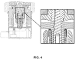
- FIG. 4 a cross-section view of rotating valve showing no rubber sealing or Lip Seal between the actuator and the rotating valve is illustrated.
- the present invention is to obviate the conventional sealing system of the device.
- a motorized water valve in accordance with the present invention is illustrated.
- the motorized water valve comprises three ways opening port 6a, 7a and 8a.
- the motorized valve is driven through ECU which controls the ON and OFF condition of motorized water valve.
- the opening of valve can be customized as per the requirement. Therefore, the system works as a control valve/Progressive valve and control the coolant flow with the same valve. During off condition the valve is closed with the help of Torsion Spring
- FIG. 6 an exploded view of the motorized water valve in accordance with the present invention is illustrated.
Landscapes
- Engineering & Computer Science (AREA)
- General Engineering & Computer Science (AREA)
- Mechanical Engineering (AREA)
- Temperature-Responsive Valves (AREA)
- Control Of Throttle Valves Provided In The Intake System Or In The Exhaust System (AREA)
Claims (6)
- Automatische Temperatursteuervorrichtung für einen Verbrennungsmotor, umfassend:einen Motorzylinder;eine elektrische Steuereinheit (ECU); undein elektromotorbetriebenes Wasserventil, das durch die elektrische Steuereinheit (ECU) angetrieben wird, wobei das elektromotorbetriebene Wasserventil verwendet wird, um die Temperatur des Motorzylinders zu steuern, wobei das elektromotorbetriebene Wasserventil eine nicht-magnetische Gehäuseanordnung (18), eine an der Gehäuseanordnung (18) befestigte Rotorabdeckungsanordnung (4) sowie eine die Rotorabdeckungsanordnung (4) und einen O-Ring-Einsatz (17) zur Abdichtung nach außen umfassende elektromagnetische Anordnung umfasst,wobei die Rotorabdeckungsanordnung (4) einen Einlassstutzen (6a), einen Hauptströmungsstutzen (8a) und einen Umgehungsstutzen (7a) umfasst, um dem Motorzylinder ein Kühlmittel zuzuführen,dadurch gekennzeichnet, dass das elektromotorbetriebene Wasserventil ferner einen bürstenlosen Gleichstrommotor (BLDC) zum Antreiben des Ventils umfasst und die elektrische Steuereinheit (ECU) den EIN- und AUS-Zustand des elektromotorbetriebenen Ventils steuert,wobei während des EIN-Zustands der Hauptströmungsstutzen geschlossen bleibt und der Umgehungsstutzen offen bleibt, um dem Motorzylinder Kühlmittel zuzuführen,wohingegen während des AUS-Zustands der Hauptströmungsstutzen offen bleibt und der Umgehungsstutzen geschlossen bleibt, wobei die elektrische Steuereinheit (ECU) dazu fähig ist, das elektromotorbetriebene Wasserventil in Zwischenzustände zu versetzen, in denen sowohl der Hauptströmungsstutzen als auch der Umgehungsstutzen gleichzeitig geschlossen oder geöffnet sind.
- Automatische Temperatursteuervorrichtung nach Anspruch 1, wobei die elektrische Steuereinheit (ECU) die Drehung des Ventils durch Verwendung einer Impulsbreitenmodulation-(PWM-)Schnittstelle im elektromotorbetriebenen Wasserventil steuert.
- Automatische Temperatursteuervorrichtung nach Anspruch 2, wobei das Wasserventil verwendet wird, um durch präzises Steuern mittels Anweisung der elektrischen Steuereinheit (ECU) den Motorzylinder in einem Zustand hoher Temperatur zu kühlen sowie den Motorzylinder in einem Zustand der Kälte zu heizen.
- Automatische Temperatursteuervorrichtung nach Anspruch 3, wobei das Gemisch aus heißem und kaltem Wasser im Auslassrohr von der an ihr anliegenden Äquivalentspannung abhängt.
- Automatische Temperatursteuervorrichtung nach Anspruch 4, wobei die Öffnung des Ventils bedarfsangepasst werden kann und das System als Steuerventil/Progressivventil fungiert.
- Verfahren zur automatischen Temperatursteuerung in einem Verbrennungsmotor mit der Vorrichtung nach einem der vorangegangenen Ansprüche, dadurch gekennzeichnet, dass das Verfahren die folgenden Schritte umfasst:a. Öffnen sowohl des Hauptströmungsstutzens (8a) als auch des Umgehungsstutzens (7a) für einen Zeitraum, der lang genug ist, um das heiße und das kalte Wasser zu vermischen, wenn der Motorzylinder kaltgestartet wird;b. Schließen beider Stutzen;c. Überwachen des Betriebszustands des Motorzylinders und/oder der Kühlmitteltemperatur; undd. Schließen des Hauptströmungsstutzens (8a), falls der Betriebszustand des Motorzylinders einen voreingestellten Pegel übersteigt; odere. Öffnen des Umgehungsstutzens (7a), falls die Kühlmitteltemperatur einen Schwellenwert übersteigt.
Applications Claiming Priority (2)
| Application Number | Priority Date | Filing Date | Title |
|---|---|---|---|
| PCT/IB2014/063086 WO2015004646A1 (en) | 2013-07-12 | 2014-07-14 | An automatic temperature control device for an internal combustion engine |
| IN2104DE2013 IN2013DE02104A (de) | 2013-07-12 | 2014-07-14 |
Publications (3)
| Publication Number | Publication Date |
|---|---|
| EP3019719A1 EP3019719A1 (de) | 2016-05-18 |
| EP3019719A4 EP3019719A4 (de) | 2017-04-05 |
| EP3019719B1 true EP3019719B1 (de) | 2018-08-01 |
Family
ID=52279412
Family Applications (1)
| Application Number | Title | Priority Date | Filing Date |
|---|---|---|---|
| EP14822827.3A Not-in-force EP3019719B1 (de) | 2013-07-12 | 2014-07-14 | Automatische temperatursteuerungsvorrichtung für einen verbrennungsmotor |
Country Status (3)
| Country | Link |
|---|---|
| EP (1) | EP3019719B1 (de) |
| IN (1) | IN2013DE02104A (de) |
| WO (1) | WO2015004646A1 (de) |
Families Citing this family (8)
| Publication number | Priority date | Publication date | Assignee | Title |
|---|---|---|---|---|
| CN105276230A (zh) * | 2015-11-30 | 2016-01-27 | 张会珍 | 一种水龙头 |
| DE102017101282A1 (de) * | 2017-01-24 | 2018-07-26 | Pierburg Gmbh | Drehschieberventil |
| DE102017105696A1 (de) * | 2017-03-16 | 2018-09-20 | Pierburg Gmbh | Drehschieberventil für den Einsatz im Kfz-Bereich |
| CN109899565B (zh) * | 2017-12-11 | 2021-02-02 | 浙江三花汽车零部件有限公司 | 一种电动阀 |
| KR102179514B1 (ko) * | 2018-06-27 | 2020-11-17 | 명성테크놀로지 주식회사 | 로터리식 3방향 밸브 |
| WO2020207573A1 (de) * | 2019-04-10 | 2020-10-15 | Pierburg Gmbh | Drehschieberventil für ein kraftfahrzeug |
| EP3953620B1 (de) * | 2019-04-10 | 2024-04-03 | Pierburg GmbH | Drehschieberventil für ein kraftfahrzeug |
| US11572961B2 (en) | 2020-07-27 | 2023-02-07 | Hanon Systems | Stackable pump and valve coolant modules |
Family Cites Families (5)
| Publication number | Priority date | Publication date | Assignee | Title |
|---|---|---|---|---|
| JP2003003846A (ja) * | 2001-06-21 | 2003-01-08 | Aisan Ind Co Ltd | エンジン冷却装置 |
| US6539899B1 (en) * | 2002-02-11 | 2003-04-01 | Visteon Global Technologies, Inc. | Rotary valve for single-point coolant diversion in engine cooling system |
| DE102006053311B4 (de) * | 2006-11-13 | 2016-10-27 | Robert Bosch Gmbh | Ventil zur Steuerung von Volumenströmen |
| US20080110435A1 (en) * | 2006-11-13 | 2008-05-15 | Oswald Baasch | Air valve and method of use |
| KR20130007819A (ko) * | 2011-07-11 | 2013-01-21 | 현대자동차주식회사 | 하이브리드 차량용 파워팩의 냉각장치 및 냉각방법 |
-
2014
- 2014-07-14 EP EP14822827.3A patent/EP3019719B1/de not_active Not-in-force
- 2014-07-14 WO PCT/IB2014/063086 patent/WO2015004646A1/en active Application Filing
- 2014-07-14 IN IN2104DE2013 patent/IN2013DE02104A/en unknown
Non-Patent Citations (1)
| Title |
|---|
| None * |
Also Published As
| Publication number | Publication date |
|---|---|
| EP3019719A4 (de) | 2017-04-05 |
| EP3019719A1 (de) | 2016-05-18 |
| WO2015004646A1 (en) | 2015-01-15 |
| IN2013DE02104A (de) | 2015-06-26 |
Similar Documents
| Publication | Publication Date | Title |
|---|---|---|
| EP3019719B1 (de) | Automatische temperatursteuerungsvorrichtung für einen verbrennungsmotor | |
| CN209369911U (zh) | 汽油机智能冷却系统 | |
| CN101368504B (zh) | 一种发动机冷却系统 | |
| CN102230417B (zh) | 不受发动机转速影响的发动机电控辅助冷却系统 | |
| WO2009129050A2 (en) | Coolant pump | |
| KR20140088922A (ko) | 연료전지 시스템의 냉각수 온도 제어 장치 및 방법 | |
| US20040098174A1 (en) | Control method of electronic control thermostat | |
| CN103352752A (zh) | 具有分流冷却功能的发动机冷却循环系统及相应的车辆 | |
| CN106541814A (zh) | 四驱轮毂驱动纯电动汽车动力总成温度集成调控系统 | |
| US6309193B1 (en) | Coolant pump for automotive use | |
| US6499963B2 (en) | Coolant pump for automotive use | |
| EP1270892B1 (de) | Wasserpumpe mit einem elektronisch gesteuerten Flüssigkeitsreibungskupplungsantrieb | |
| CN101709664B (zh) | 一种基于一体化永磁同步电机水泵和电子调速技术的内燃机冷却系统 | |
| CN109854429A (zh) | 用于发动机冷却液的加热系统 | |
| US20130108442A1 (en) | Variable-geometry fan and method for control thereof | |
| US20150034027A1 (en) | Hybrid electromechanical coolant pump | |
| CN103306800B (zh) | 车辆用内燃机的冷却设备 | |
| CN111441860B (zh) | 一种应用电子温控阀的发动机热管理系统及其实现方法 | |
| CN204024789U (zh) | 发动机冷却系统及具有其的汽车 | |
| CN203373802U (zh) | 基于硅油离合器的挖掘机散热控制系统 | |
| CN110861485A (zh) | 混合动力车散热器总成、散热系统和方法及混合动力车 | |
| CN212671929U (zh) | 一种电动水泵冷却系统 | |
| CN203604034U (zh) | 一种发动机热管理系统 | |
| CN213063739U (zh) | 一种应用电子温控阀的发动机热管理系统 | |
| CN100545430C (zh) | 一种发动机水温调节装置 |
Legal Events
| Date | Code | Title | Description |
|---|---|---|---|
| PUAI | Public reference made under article 153(3) epc to a published international application that has entered the european phase |
Free format text: ORIGINAL CODE: 0009012 |
|
| 17P | Request for examination filed |
Effective date: 20160202 |
|
| AK | Designated contracting states |
Kind code of ref document: A1 Designated state(s): AL AT BE BG CH CY CZ DE DK EE ES FI FR GB GR HR HU IE IS IT LI LT LU LV MC MK MT NL NO PL PT RO RS SE SI SK SM TR |
|
| AX | Request for extension of the european patent |
Extension state: BA ME |
|
| DAX | Request for extension of the european patent (deleted) | ||
| A4 | Supplementary search report drawn up and despatched |
Effective date: 20170302 |
|
| RIC1 | Information provided on ipc code assigned before grant |
Ipc: F01P 7/14 20060101AFI20170224BHEP Ipc: F16K 11/085 20060101ALI20170224BHEP Ipc: B60H 1/00 20060101ALI20170224BHEP Ipc: F16K 11/00 20060101ALI20170224BHEP Ipc: F16K 31/04 20060101ALI20170224BHEP |
|
| GRAP | Despatch of communication of intention to grant a patent |
Free format text: ORIGINAL CODE: EPIDOSNIGR1 |
|
| STAA | Information on the status of an ep patent application or granted ep patent |
Free format text: STATUS: GRANT OF PATENT IS INTENDED |
|
| INTG | Intention to grant announced |
Effective date: 20180208 |
|
| GRAS | Grant fee paid |
Free format text: ORIGINAL CODE: EPIDOSNIGR3 |
|
| GRAA | (expected) grant |
Free format text: ORIGINAL CODE: 0009210 |
|
| STAA | Information on the status of an ep patent application or granted ep patent |
Free format text: STATUS: THE PATENT HAS BEEN GRANTED |
|
| AK | Designated contracting states |
Kind code of ref document: B1 Designated state(s): AL AT BE BG CH CY CZ DE DK EE ES FI FR GB GR HR HU IE IS IT LI LT LU LV MC MK MT NL NO PL PT RO RS SE SI SK SM TR |
|
| REG | Reference to a national code |
Ref country code: GB Ref legal event code: FG4D |
|
| REG | Reference to a national code |
Ref country code: CH Ref legal event code: EP Ref country code: AT Ref legal event code: REF Ref document number: 1024565 Country of ref document: AT Kind code of ref document: T Effective date: 20180815 |
|
| REG | Reference to a national code |
Ref country code: IE Ref legal event code: FG4D |
|
| REG | Reference to a national code |
Ref country code: DE Ref legal event code: R096 Ref document number: 602014029680 Country of ref document: DE |
|
| REG | Reference to a national code |
Ref country code: NL Ref legal event code: MP Effective date: 20180801 |
|
| REG | Reference to a national code |
Ref country code: LT Ref legal event code: MG4D |
|
| REG | Reference to a national code |
Ref country code: AT Ref legal event code: MK05 Ref document number: 1024565 Country of ref document: AT Kind code of ref document: T Effective date: 20180801 |
|
| PG25 | Lapsed in a contracting state [announced via postgrant information from national office to epo] |
Ref country code: GR Free format text: LAPSE BECAUSE OF FAILURE TO SUBMIT A TRANSLATION OF THE DESCRIPTION OR TO PAY THE FEE WITHIN THE PRESCRIBED TIME-LIMIT Effective date: 20181102 Ref country code: NO Free format text: LAPSE BECAUSE OF FAILURE TO SUBMIT A TRANSLATION OF THE DESCRIPTION OR TO PAY THE FEE WITHIN THE PRESCRIBED TIME-LIMIT Effective date: 20181101 Ref country code: AT Free format text: LAPSE BECAUSE OF FAILURE TO SUBMIT A TRANSLATION OF THE DESCRIPTION OR TO PAY THE FEE WITHIN THE PRESCRIBED TIME-LIMIT Effective date: 20180801 Ref country code: IS Free format text: LAPSE BECAUSE OF FAILURE TO SUBMIT A TRANSLATION OF THE DESCRIPTION OR TO PAY THE FEE WITHIN THE PRESCRIBED TIME-LIMIT Effective date: 20181201 Ref country code: LT Free format text: LAPSE BECAUSE OF FAILURE TO SUBMIT A TRANSLATION OF THE DESCRIPTION OR TO PAY THE FEE WITHIN THE PRESCRIBED TIME-LIMIT Effective date: 20180801 Ref country code: NL Free format text: LAPSE BECAUSE OF FAILURE TO SUBMIT A TRANSLATION OF THE DESCRIPTION OR TO PAY THE FEE WITHIN THE PRESCRIBED TIME-LIMIT Effective date: 20180801 Ref country code: BG Free format text: LAPSE BECAUSE OF FAILURE TO SUBMIT A TRANSLATION OF THE DESCRIPTION OR TO PAY THE FEE WITHIN THE PRESCRIBED TIME-LIMIT Effective date: 20181101 Ref country code: FI Free format text: LAPSE BECAUSE OF FAILURE TO SUBMIT A TRANSLATION OF THE DESCRIPTION OR TO PAY THE FEE WITHIN THE PRESCRIBED TIME-LIMIT Effective date: 20180801 Ref country code: PL Free format text: LAPSE BECAUSE OF FAILURE TO SUBMIT A TRANSLATION OF THE DESCRIPTION OR TO PAY THE FEE WITHIN THE PRESCRIBED TIME-LIMIT Effective date: 20180801 Ref country code: RS Free format text: LAPSE BECAUSE OF FAILURE TO SUBMIT A TRANSLATION OF THE DESCRIPTION OR TO PAY THE FEE WITHIN THE PRESCRIBED TIME-LIMIT Effective date: 20180801 Ref country code: SE Free format text: LAPSE BECAUSE OF FAILURE TO SUBMIT A TRANSLATION OF THE DESCRIPTION OR TO PAY THE FEE WITHIN THE PRESCRIBED TIME-LIMIT Effective date: 20180801 |
|
| PG25 | Lapsed in a contracting state [announced via postgrant information from national office to epo] |
Ref country code: LV Free format text: LAPSE BECAUSE OF FAILURE TO SUBMIT A TRANSLATION OF THE DESCRIPTION OR TO PAY THE FEE WITHIN THE PRESCRIBED TIME-LIMIT Effective date: 20180801 Ref country code: AL Free format text: LAPSE BECAUSE OF FAILURE TO SUBMIT A TRANSLATION OF THE DESCRIPTION OR TO PAY THE FEE WITHIN THE PRESCRIBED TIME-LIMIT Effective date: 20180801 Ref country code: HR Free format text: LAPSE BECAUSE OF FAILURE TO SUBMIT A TRANSLATION OF THE DESCRIPTION OR TO PAY THE FEE WITHIN THE PRESCRIBED TIME-LIMIT Effective date: 20180801 |
|
| PG25 | Lapsed in a contracting state [announced via postgrant information from national office to epo] |
Ref country code: EE Free format text: LAPSE BECAUSE OF FAILURE TO SUBMIT A TRANSLATION OF THE DESCRIPTION OR TO PAY THE FEE WITHIN THE PRESCRIBED TIME-LIMIT Effective date: 20180801 Ref country code: IT Free format text: LAPSE BECAUSE OF FAILURE TO SUBMIT A TRANSLATION OF THE DESCRIPTION OR TO PAY THE FEE WITHIN THE PRESCRIBED TIME-LIMIT Effective date: 20180801 Ref country code: ES Free format text: LAPSE BECAUSE OF FAILURE TO SUBMIT A TRANSLATION OF THE DESCRIPTION OR TO PAY THE FEE WITHIN THE PRESCRIBED TIME-LIMIT Effective date: 20180801 Ref country code: RO Free format text: LAPSE BECAUSE OF FAILURE TO SUBMIT A TRANSLATION OF THE DESCRIPTION OR TO PAY THE FEE WITHIN THE PRESCRIBED TIME-LIMIT Effective date: 20180801 Ref country code: CZ Free format text: LAPSE BECAUSE OF FAILURE TO SUBMIT A TRANSLATION OF THE DESCRIPTION OR TO PAY THE FEE WITHIN THE PRESCRIBED TIME-LIMIT Effective date: 20180801 |
|
| REG | Reference to a national code |
Ref country code: DE Ref legal event code: R097 Ref document number: 602014029680 Country of ref document: DE |
|
| PG25 | Lapsed in a contracting state [announced via postgrant information from national office to epo] |
Ref country code: DK Free format text: LAPSE BECAUSE OF FAILURE TO SUBMIT A TRANSLATION OF THE DESCRIPTION OR TO PAY THE FEE WITHIN THE PRESCRIBED TIME-LIMIT Effective date: 20180801 Ref country code: SM Free format text: LAPSE BECAUSE OF FAILURE TO SUBMIT A TRANSLATION OF THE DESCRIPTION OR TO PAY THE FEE WITHIN THE PRESCRIBED TIME-LIMIT Effective date: 20180801 Ref country code: SK Free format text: LAPSE BECAUSE OF FAILURE TO SUBMIT A TRANSLATION OF THE DESCRIPTION OR TO PAY THE FEE WITHIN THE PRESCRIBED TIME-LIMIT Effective date: 20180801 |
|
| PLBE | No opposition filed within time limit |
Free format text: ORIGINAL CODE: 0009261 |
|
| STAA | Information on the status of an ep patent application or granted ep patent |
Free format text: STATUS: NO OPPOSITION FILED WITHIN TIME LIMIT |
|
| 26N | No opposition filed |
Effective date: 20190503 |
|
| PG25 | Lapsed in a contracting state [announced via postgrant information from national office to epo] |
Ref country code: SI Free format text: LAPSE BECAUSE OF FAILURE TO SUBMIT A TRANSLATION OF THE DESCRIPTION OR TO PAY THE FEE WITHIN THE PRESCRIBED TIME-LIMIT Effective date: 20180801 |
|
| PG25 | Lapsed in a contracting state [announced via postgrant information from national office to epo] |
Ref country code: MC Free format text: LAPSE BECAUSE OF FAILURE TO SUBMIT A TRANSLATION OF THE DESCRIPTION OR TO PAY THE FEE WITHIN THE PRESCRIBED TIME-LIMIT Effective date: 20180801 |
|
| REG | Reference to a national code |
Ref country code: CH Ref legal event code: PL |
|
| PG25 | Lapsed in a contracting state [announced via postgrant information from national office to epo] |
Ref country code: TR Free format text: LAPSE BECAUSE OF FAILURE TO SUBMIT A TRANSLATION OF THE DESCRIPTION OR TO PAY THE FEE WITHIN THE PRESCRIBED TIME-LIMIT Effective date: 20180801 |
|
| REG | Reference to a national code |
Ref country code: BE Ref legal event code: MM Effective date: 20190731 |
|
| PG25 | Lapsed in a contracting state [announced via postgrant information from national office to epo] |
Ref country code: LI Free format text: LAPSE BECAUSE OF NON-PAYMENT OF DUE FEES Effective date: 20190731 Ref country code: CH Free format text: LAPSE BECAUSE OF NON-PAYMENT OF DUE FEES Effective date: 20190731 Ref country code: LU Free format text: LAPSE BECAUSE OF NON-PAYMENT OF DUE FEES Effective date: 20190714 Ref country code: BE Free format text: LAPSE BECAUSE OF NON-PAYMENT OF DUE FEES Effective date: 20190731 |
|
| PG25 | Lapsed in a contracting state [announced via postgrant information from national office to epo] |
Ref country code: PT Free format text: LAPSE BECAUSE OF FAILURE TO SUBMIT A TRANSLATION OF THE DESCRIPTION OR TO PAY THE FEE WITHIN THE PRESCRIBED TIME-LIMIT Effective date: 20181201 |
|
| PG25 | Lapsed in a contracting state [announced via postgrant information from national office to epo] |
Ref country code: IE Free format text: LAPSE BECAUSE OF NON-PAYMENT OF DUE FEES Effective date: 20190714 |
|
| PG25 | Lapsed in a contracting state [announced via postgrant information from national office to epo] |
Ref country code: CY Free format text: LAPSE BECAUSE OF FAILURE TO SUBMIT A TRANSLATION OF THE DESCRIPTION OR TO PAY THE FEE WITHIN THE PRESCRIBED TIME-LIMIT Effective date: 20180801 |
|
| PG25 | Lapsed in a contracting state [announced via postgrant information from national office to epo] |
Ref country code: HU Free format text: LAPSE BECAUSE OF FAILURE TO SUBMIT A TRANSLATION OF THE DESCRIPTION OR TO PAY THE FEE WITHIN THE PRESCRIBED TIME-LIMIT; INVALID AB INITIO Effective date: 20140714 Ref country code: MT Free format text: LAPSE BECAUSE OF FAILURE TO SUBMIT A TRANSLATION OF THE DESCRIPTION OR TO PAY THE FEE WITHIN THE PRESCRIBED TIME-LIMIT Effective date: 20180801 |
|
| PGFP | Annual fee paid to national office [announced via postgrant information from national office to epo] |
Ref country code: FR Payment date: 20210730 Year of fee payment: 8 |
|
| PGFP | Annual fee paid to national office [announced via postgrant information from national office to epo] |
Ref country code: GB Payment date: 20210803 Year of fee payment: 8 Ref country code: DE Payment date: 20210803 Year of fee payment: 8 |
|
| PG25 | Lapsed in a contracting state [announced via postgrant information from national office to epo] |
Ref country code: MK Free format text: LAPSE BECAUSE OF FAILURE TO SUBMIT A TRANSLATION OF THE DESCRIPTION OR TO PAY THE FEE WITHIN THE PRESCRIBED TIME-LIMIT Effective date: 20180801 |
|
| REG | Reference to a national code |
Ref country code: DE Ref legal event code: R119 Ref document number: 602014029680 Country of ref document: DE |
|
| GBPC | Gb: european patent ceased through non-payment of renewal fee |
Effective date: 20220714 |
|
| PG25 | Lapsed in a contracting state [announced via postgrant information from national office to epo] |
Ref country code: FR Free format text: LAPSE BECAUSE OF NON-PAYMENT OF DUE FEES Effective date: 20220731 |
|
| PG25 | Lapsed in a contracting state [announced via postgrant information from national office to epo] |
Ref country code: GB Free format text: LAPSE BECAUSE OF NON-PAYMENT OF DUE FEES Effective date: 20220714 Ref country code: DE Free format text: LAPSE BECAUSE OF NON-PAYMENT OF DUE FEES Effective date: 20230201 |