EP3019687B1 - Dynamic seal tube for a down hole hammer drill - Google Patents
Dynamic seal tube for a down hole hammer drill Download PDFInfo
- Publication number
- EP3019687B1 EP3019687B1 EP14823597.1A EP14823597A EP3019687B1 EP 3019687 B1 EP3019687 B1 EP 3019687B1 EP 14823597 A EP14823597 A EP 14823597A EP 3019687 B1 EP3019687 B1 EP 3019687B1
- Authority
- EP
- European Patent Office
- Prior art keywords
- piston
- tube
- port
- drill bit
- pressurized fluid
- Prior art date
- Legal status (The legal status is an assumption and is not a legal conclusion. Google has not performed a legal analysis and makes no representation as to the accuracy of the status listed.)
- Active
Links
- 239000012530 fluid Substances 0.000 claims description 41
- 238000013022 venting Methods 0.000 claims description 8
- 230000001419 dependent effect Effects 0.000 claims 1
- 230000002093 peripheral effect Effects 0.000 description 6
- 230000000717 retained effect Effects 0.000 description 6
- 230000014759 maintenance of location Effects 0.000 description 4
- 239000011435 rock Substances 0.000 description 4
- 238000005520 cutting process Methods 0.000 description 3
- 238000013461 design Methods 0.000 description 3
- 239000000463 material Substances 0.000 description 3
- 230000009471 action Effects 0.000 description 2
- 238000013459 approach Methods 0.000 description 2
- 230000008901 benefit Effects 0.000 description 2
- 230000000694 effects Effects 0.000 description 2
- 238000000034 method Methods 0.000 description 2
- 238000004140 cleaning Methods 0.000 description 1
- 230000001934 delay Effects 0.000 description 1
- 230000003111 delayed effect Effects 0.000 description 1
- 238000011161 development Methods 0.000 description 1
- 239000000428 dust Substances 0.000 description 1
- 238000011010 flushing procedure Methods 0.000 description 1
- 239000012634 fragment Substances 0.000 description 1
- 230000003993 interaction Effects 0.000 description 1
- 230000007246 mechanism Effects 0.000 description 1
- 238000012986 modification Methods 0.000 description 1
- 230000004048 modification Effects 0.000 description 1
- 238000009527 percussion Methods 0.000 description 1
- 230000000737 periodic effect Effects 0.000 description 1
- 229920000642 polymer Polymers 0.000 description 1
- 238000002360 preparation method Methods 0.000 description 1
- 230000008569 process Effects 0.000 description 1
- 230000000284 resting effect Effects 0.000 description 1
- 230000002441 reversible effect Effects 0.000 description 1
- 238000000926 separation method Methods 0.000 description 1
- XLYOFNOQVPJJNP-UHFFFAOYSA-N water Substances O XLYOFNOQVPJJNP-UHFFFAOYSA-N 0.000 description 1
Images

Classifications
-
- E—FIXED CONSTRUCTIONS
- E21—EARTH OR ROCK DRILLING; MINING
- E21B—EARTH OR ROCK DRILLING; OBTAINING OIL, GAS, WATER, SOLUBLE OR MELTABLE MATERIALS OR A SLURRY OF MINERALS FROM WELLS
- E21B4/00—Drives for drilling, used in the borehole
- E21B4/06—Down-hole impacting means, e.g. hammers
- E21B4/14—Fluid operated hammers
-
- E—FIXED CONSTRUCTIONS
- E21—EARTH OR ROCK DRILLING; MINING
- E21B—EARTH OR ROCK DRILLING; OBTAINING OIL, GAS, WATER, SOLUBLE OR MELTABLE MATERIALS OR A SLURRY OF MINERALS FROM WELLS
- E21B21/00—Methods or apparatus for flushing boreholes, e.g. by use of exhaust air from motor
- E21B21/10—Valve arrangements in drilling-fluid circulation systems
Definitions
- the present invention relates to pressurized fluid-driven impact I percussion tools and in particular to down hole hammer drills.
- the current down hole drill is a reciprocative impact tool that attaches to the end of a drill string and examples of such tools are disclosed in patent applications having publication numbers; US 4100976 , WO99/28586A1 , US3826316A , US3193024A , US3387671A and US4923018 .
- the down hole hammer drill consists of a piston moving up and down within a housing repeatedly striking a drill bit anvil.
- the down hole hammer drill has a reciprocating action and the repeated impact of the piston on the anvil face of a drill bit fractures the rock.
- the fast hammer action breaks rock into small flakes and dust and is blown clear by the exhaust from the down hole hammer drill. Drill pipes are added successively as the hole becomes deeper.
- Pressurized fluid moves the piston up and down as directed by fluid passing through ports which are uncovered during the movement of the piston.
- Pressurized fluid enters the hammer through a bore in the back-head, opens a check valve and flows through channels to the lower chamber formed between the piston and the drill bit.
- the piston is forced upward. The upward movement continues until the piston pulls off the stationary foot valve. This allows pressurized fluid to exhaust from the lower chamber through the hollow said foot valve and drill bit and into the borehole area being drilled.
- a piston recess aligns with a port to allow fluid flow into the upper chamber. Exhaust passages in the upper chamber have been sealed by the piston and the pressure in the upper chamber increases.
- the increased pressure in the upper chamber causes the piston to decelerate, stop and then move in the reverse direction.
- the upper chamber begins to exhaust.
- the cycle is immediately repeated.
- the drill bit moves freely in the chuck splines so that impact force is transmitted to drill bit cutting elements to produce rock chips.
- the drill bit drops to an extended position where it's top shoulder rests on a retainer ring.
- the drill operator can flush water and debris from the hole and accelerate periodic borehole cleaning when required.
- the reciprocation of the down hole hammer entails a foot valve that is rigid and fixed in the bore of the drill bit shank and extends from the anvil face.
- the piston slideably engages with the fixed foot valve on the downward impact stroke forming a sealed chamber causing the piston to decelerate until it impacts with the anvil face of the drill bit.
- the deceleration of the piston results in transferring a reduced impact force. This problem is seen as an unavoidable inefficiency as the increased pressure in the lower chamber is necessary in order to accelerate the piston upward to start a new cycle.
- the present invention provides a down hole hammer drill as recited in attached claim 1. This was developed as a result of viewing the problem differently and taking an alternate approach. The approach taken was to control the timing of the flow of fluid from the lower chamber thereby reducing the deceleration of the piston.
- the inventor has developed a dynamic seal tube that moves and seals in coordination with the moving piston.
- the dynamic seal tube is a tube that slides within the bore of the piston and the anvil portion of the drill bit and co-operatively acts to release different volumes of pressurized fluid from the lower chamber when the piston is in different predetermined positions.
- the dynamic seal tube is retained within both the piston and the drill bit.
- the dynamic seal tube moves between a seat in the piston and a seat in the drill bit while at the same time co-operating with the movement of the piston to allow air to exhaust through the dynamic port when the piston is in a predetermined position.
- the dynamic seal tube has a peripheral lip substantially at one end and in use the dynamic seal tube is retained within the piston and the drill bit by at least one seat in the piston.
- the dynamic seal tube is preferably retained by at least one seat I detent or protrusion in a lower portion of the piston bore and an anvil portion of the drill bit bore.
- a peripheral lip retained within the piston moves between two seats I detents within the internal bore of the piston.
- Said at least one dynamic port preferably enables venting of the space between the drill bit and the piston for a selected part of the downward stroke of the piston.
- the selected part is that part of the downward stroke of the piston when the dynamic port is not sealed by the drill bit.
- Venting from the dynamic port is preferably prevented when the dynamic seal tube slides within the drill bit during part of the upward stroke of the piston. Venting is preferably prevented during an early stage of the upward stroke of the piston.
- Venting from the dynamic port is preferably delayed when the dynamic seal tube slides within the drill bit during the upward stroke of the piston and then enabled when the dynamic port becomes uncovered.
- the dynamic port is covered when the peripheral lip abuts the seat in the drill bit bore and is retained within the drill bit.
- the port tube extends through the piston bore and positions within the drill bit bore.
- the dynamic seal tube is preferably positioned between the port tube and the internal bore surfaces of the piston and the drill bit. When the dynamic seal tube is raised, it co-operates with the port tube to provide access to an exhaust port when the piston is in a predetermined position.
- the spring-biased check valve is located within the port tube and has a check valve body that is biased to an upper closed position and adapted to close against a lower port tube seat so that when the check valve body is in the upper closed position it is not closed against the lower port tube seat allowing pressurized fluid to divert to a lower section of the port tube and when the check valve body is not in the upper closed position the check valve body is closed against the lower port tube seat thereby preventing diversion of pressurized fluid to the lower section of the port tube.
- the movement of the check valve body on and off the lower port tube seat forms a diverting check valve.
- the check valve body When the pressure in a lower chamber formed between the piston and the drill bit exceeds and stalls the incoming pressurized fluid supply, the check valve body preferably moves towards its upper closed position and lifts off the lower port tube seat to allow pressurized fluid to enter the lower section of the port tube and exhaust bore of the port tube.
- the design and location of the check valve within the check valve I port tube assembly provides a timely flow of pressurized fluid through the exhaust bore to reduce the abrupt deceleration of the piston.
- the spring-biased check valve can be used in conjunction and cooperatively with the dynamic seal tube as previously described in its various forms and aspects.
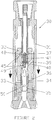
- FIG. 1 With reference to Figure 1 , there is shown a down hole hammer drill 10 having a drill housing 11, piston 12, drill bit 13 and dynamic seal tube 14.
- the dynamic seal tube 14 has dynamic port 15.
- a series of diagrammatic views (A to F) of the movement of the dynamic seal tube 14 during different phases of the cycle of the piston 12 is shown.
- Fig.1A there is shown a view of the piston 12 at rest atop the drill bit 13 with the dynamic seal tube 14 captive in the bores of both piston and drill bit anvil.
- pressurized fluid introduced via the porting system forces the piston 12 upward and when the limit of the captive stroke of the dynamic seal tube 14 within the piston bore 19 is reached by the upper peripheral tube lip 20 abutting the piston detent 21, the space 18 between the piston 12 and drill bit 13 is still pressurized and the piston 12 continues to rise, pulling the lower peripheral lip 20 past lower detent 24.
- Fig.1C the piston 12 continues to lift the dynamic seal tube 14 which is now being extended upwardly from within the captive bore of the drill bit 13.
- the exhaust port 15 of the dynamic seal tube 14 is open to the pressurized space 18 and the fluid can now pass through to the cutting face of the drill bit 13 for flushing of rock fragment cuttings.
- the porting system is charging the upper chamber 27 in preparation for the downward stroke.
- Fig.1F the piston 12 impact with the drill bit 13 is imminent.
- the piston 12 has pushed the dynamic seal tube 14 downward so that the exhaust port 15 is covered and is no longer open to vent from the space 18. Up to this point the downwardly moving piston 12 has not been impeded I decelerated by pressurized fluid in the space 18. As illustrated, a small fraction of the piston stroke remains as a sealed space 18 in which some pressurization may build.
- the porting system has vented the upper chamber and is now pressurizing the space 18 in order to effect the upward stroke.
- the dynamic seal tube 14 can be designed so that the exhaust port 15 can be positioned higher or lower so as to alter the duration of resistance to the downward movement of the piston 12. The higher the position of the exhaust port 15, the less resistance to the downward movement of the piston 12. The less resistance to the downward movement of the piston 12, greater is the amount of impact energy transferred.
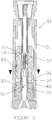
- a down hole hammer drill in accordance with the present invention is shown in Figures 2 to 4 .
- This functions in a manner similar to the drill of Figure 1 and comprises a down hole hammer drill 30 having a drill housing 31, piston 32, drill bit 33, a port tube 35 and dynamic seal tube 34.
- the piston 32 is moving downward towards the drill bit 33.
- the dynamic seal tube 34 has closed the path of exhaust air to the lower chamber exhaust port 50 and the piston 32 is pressurizing fluid in the lower chamber 36.
- a pressure spike is formed as the pressure in lower chamber 36 exceeds and stalls the incoming pressurized supply.
- the spring 41 biases the check valve 37 toward its upper closed position.
- the check valve serves to eliminate the air distributor component of a traditional hammer drill and shortens the overall assembly.
- the position of the check valve within the hammer drill assembly and the design of the check valve provides an advantage that enables the hammer drill to be considerably shorter and weigh less than traditional hammer drills. This advantage translates to a less expensive hammer drill and a hammer drill that can be easy to work with and handled.
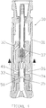
- the hammer drill is shown prior to impact.
- the piston 32 descends during the power stroke with the dynamic seal tube 34 fully retracted due to frictional interaction with the port tube and/or due to contact with a linear detent 46 on the port tube, where at a fixed point the pressurized supply of the lower chamber 36 begins via the alignment of supply port 48 and conduit 49.
- a detent I positioning mechanism within any embodiment may take more than one form in order to effect the desired positioning of the dynamic seal tube during the operational cycle.
- hammer drill 30 is shown after impact.
- the lower chamber 36 continues to be charged with pressurized fluid, the piston 33 rises and the dynamic seal tube 34 remains held by linear detent 46 to ensure the dynamic seal tube is at its maximum extent within the piston so that a sufficient duration of pressurization lifts the piston 32 and the dynamic seal tube then moves upward until the lower chamber exhaust port 50 is again exposed to enable discharge from the lower chamber 36.
- the piston 32, together with the dynamic seal tube 34 continues to rise under the momentum until pressurization of the upper chamber halts and reverses the piston and the cycle repeats.
- the pressurization cycles are fixed and only the exhaust function of the lower chamber during the impact I power stroke is variable via the dimensional determination (selected linear engagement and length) of the Dynamic Seal Tube.
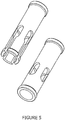
- the dynamic seal tube shown in Figure 1 may be configured to have a greater retaining capacity in one of the piston or drill bit.
- the dynamic seal tube is preferably configured or shaped to allow relatively easy separation from the drill bit so that the drill bit can be replaced while retaining the functionality of the dynamic seal tube.
- the dynamic seal tube arrangement is configured or shaped to function upside down, where the dominant captive retention is configured in the drill bit and the more easily removed portion in the piston.
- one end has at least one slot to provide a degree of flexibility and have a different retention capacity compared with the other end.
- the number of slots and the length of the slots can vary depending on the amount of desired retention, and/or desired fluid bypass.
- the material from which the dynamic seal tube is made can affect the retention capacity.
- the preferred material of the dynamic seal tube is a plastic polymer selected to withstand the operational environment.
- a metallic dynamic seal tube is also a practical alternative.
Landscapes
- Engineering & Computer Science (AREA)
- Life Sciences & Earth Sciences (AREA)
- Geology (AREA)
- Mining & Mineral Resources (AREA)
- Mechanical Engineering (AREA)
- Physics & Mathematics (AREA)
- Environmental & Geological Engineering (AREA)
- Fluid Mechanics (AREA)
- General Life Sciences & Earth Sciences (AREA)
- Geochemistry & Mineralogy (AREA)
- Earth Drilling (AREA)
Applications Claiming Priority (2)
| Application Number | Priority Date | Filing Date | Title |
|---|---|---|---|
| AU2013902580A AU2013902580A0 (en) | 2013-07-12 | Dynamic seal tube for a down hole hammer drill | |
| PCT/AU2014/000709 WO2015003215A1 (en) | 2013-07-12 | 2014-07-10 | Dynamic seal tube for a down hole hammer drill |
Publications (3)
| Publication Number | Publication Date |
|---|---|
| EP3019687A1 EP3019687A1 (en) | 2016-05-18 |
| EP3019687A4 EP3019687A4 (en) | 2017-03-29 |
| EP3019687B1 true EP3019687B1 (en) | 2019-09-04 |
Family
ID=52279225
Family Applications (1)
| Application Number | Title | Priority Date | Filing Date |
|---|---|---|---|
| EP14823597.1A Active EP3019687B1 (en) | 2013-07-12 | 2014-07-10 | Dynamic seal tube for a down hole hammer drill |
Country Status (9)
| Country | Link |
|---|---|
| US (1) | US10161188B2 (zh) |
| EP (1) | EP3019687B1 (zh) |
| KR (1) | KR20160029854A (zh) |
| CN (1) | CN105378206B (zh) |
| AU (1) | AU2014289968A1 (zh) |
| BR (1) | BR112016000569B1 (zh) |
| CL (1) | CL2016000002A1 (zh) |
| WO (1) | WO2015003215A1 (zh) |
| ZA (1) | ZA201600570B (zh) |
Families Citing this family (4)
| Publication number | Priority date | Publication date | Assignee | Title |
|---|---|---|---|---|
| WO2016154703A1 (en) * | 2015-03-27 | 2016-10-06 | Anderson, Charles Abernethy | Apparatus and method for modifying axial force |
| KR101882380B1 (ko) * | 2016-03-24 | 2018-08-24 | 인석신 | 워터해머 장치 |
| SE1951244A1 (en) * | 2019-10-31 | 2021-04-20 | Epiroc Drilling Tools Ab | Pneumatic drill hammer comprising a boost chamber and a drilling rig comprising such a drill hammer |
| WO2023128842A1 (en) * | 2021-12-27 | 2023-07-06 | Epiroc Drilling Tools Aktiebolag | Down-the-hole hammer |
Citations (1)
| Publication number | Priority date | Publication date | Assignee | Title |
|---|---|---|---|---|
| US4100976A (en) * | 1976-12-06 | 1978-07-18 | Reed Tool Co. | Pneumatic impact drilling tool |
Family Cites Families (17)
| Publication number | Priority date | Publication date | Assignee | Title |
|---|---|---|---|---|
| US80067A (en) | 1868-07-21 | Henky t | ||
| US3193024A (en) | 1962-01-18 | 1965-07-06 | Atlantic Refining Co | Percussion drills with exhaust passage in hammer |
| US3387671A (en) | 1965-10-15 | 1968-06-11 | Mission Mfg Co | Percussion tool |
| US3527239A (en) * | 1968-09-26 | 1970-09-08 | Gardner Denver Co | Exhaust tube for down-hole drill |
| US3826316A (en) * | 1971-02-19 | 1974-07-30 | Reed Tool Co | Pneumatic impact tool |
| DE2816737C3 (de) * | 1978-04-18 | 1981-03-19 | Hans Philipp 3570 Stadtallendorf Walter | Bohrhammer, Insbesondere Tieflochhammer |
| US4923018A (en) | 1989-03-02 | 1990-05-08 | Sandvik Rock Tools, Inc. | Percussion drill |
| US5033557A (en) * | 1990-05-07 | 1991-07-23 | Anadrill, Inc. | Hydraulic drilling jar |
| AUPP061997A0 (en) * | 1997-11-28 | 1998-01-08 | Rear, Ian Graeme | Top-sub assembly of a downhole hammer |
| US5984021A (en) | 1998-01-27 | 1999-11-16 | Numa Tool Company | Porting system for back chamber of pneumatic hammer |
| US6499544B1 (en) * | 2000-11-15 | 2002-12-31 | Sandvik Ab | Percussive down-the-hole hammer for rock drilling, and a one-way valve used therein |
| US6883618B1 (en) | 2004-06-15 | 2005-04-26 | Numa Tool Company | Variable timing for front chamber of pneumatic hammer |
| US7267205B2 (en) | 2005-08-31 | 2007-09-11 | Shimano, Inc. | Apparatus for actuating a bicycle hub brake |
| US9068399B2 (en) * | 2006-10-20 | 2015-06-30 | Drillroc Pneumatic Pty Ltd | Down-the-hole hammer drill |
| CA2672175C (en) * | 2006-10-20 | 2015-05-12 | Drillroc Pneumatic Pty Ltd | Down-the-hole hammer drill |
| US8011455B2 (en) * | 2009-02-11 | 2011-09-06 | Atlas Copco Secoroc Llc | Down hole hammer having elevated exhaust |
| CN201560742U (zh) * | 2010-01-05 | 2010-08-25 | 中国石油集团川庆钻探工程有限公司 | 潜孔冲击器钎头单向截止阀 |
-
2014
- 2014-07-10 EP EP14823597.1A patent/EP3019687B1/en active Active
- 2014-07-10 AU AU2014289968A patent/AU2014289968A1/en not_active Abandoned
- 2014-07-10 CN CN201480039475.XA patent/CN105378206B/zh active Active
- 2014-07-10 BR BR112016000569-4A patent/BR112016000569B1/pt active IP Right Grant
- 2014-07-10 KR KR1020167003662A patent/KR20160029854A/ko not_active Application Discontinuation
- 2014-07-10 WO PCT/AU2014/000709 patent/WO2015003215A1/en active Application Filing
- 2014-07-10 US US14/904,506 patent/US10161188B2/en active Active
-
2016
- 2016-01-04 CL CL2016000002A patent/CL2016000002A1/es unknown
- 2016-01-26 ZA ZA2016/00570A patent/ZA201600570B/en unknown
Patent Citations (1)
| Publication number | Priority date | Publication date | Assignee | Title |
|---|---|---|---|---|
| US4100976A (en) * | 1976-12-06 | 1978-07-18 | Reed Tool Co. | Pneumatic impact drilling tool |
Also Published As
| Publication number | Publication date |
|---|---|
| EP3019687A4 (en) | 2017-03-29 |
| KR20160029854A (ko) | 2016-03-15 |
| US20160153237A1 (en) | 2016-06-02 |
| EP3019687A1 (en) | 2016-05-18 |
| AU2014289968A1 (en) | 2016-03-03 |
| US10161188B2 (en) | 2018-12-25 |
| BR112016000569B1 (pt) | 2022-01-25 |
| ZA201600570B (en) | 2021-04-28 |
| CL2016000002A1 (es) | 2016-09-16 |
| WO2015003215A1 (en) | 2015-01-15 |
| CN105378206B (zh) | 2019-03-26 |
| BR112016000569A2 (zh) | 2017-07-25 |
| CN105378206A (zh) | 2016-03-02 |
Similar Documents
| Publication | Publication Date | Title |
|---|---|---|
| EP3019687B1 (en) | Dynamic seal tube for a down hole hammer drill | |
| TWI574796B (zh) | 扣緊工具 | |
| KR101138987B1 (ko) | 자동 행정거리 전환기능이 구비된 유압 브레이커 | |
| US7784561B2 (en) | Ground drilling hammer and the driving method | |
| SU845796A3 (ru) | Гидравлическое устройство ударногодЕйСТВи | |
| EA027551B1 (ru) | Забойный ударник с поднятым выпуском | |
| EP1697089B1 (en) | Impact tool | |
| RU155225U1 (ru) | Циркуляционный переводник бурильной колонны | |
| KR20100039036A (ko) | 유압브레이커 | |
| US3425498A (en) | Fluid actuated vibrator devices | |
| KR20160098229A (ko) | 충격구동 공구 | |
| EP2812158B1 (en) | Sleeve for a pneumatic fastener-driving tool | |
| KR20090041823A (ko) | 유압브레이커의 자동타격조정장치 | |
| RU68587U1 (ru) | Устройство для создания перфорационных каналов в обсадной колонне скважины | |
| CN105710845B (zh) | 具有可变冲程控制的液压锤 | |
| US4142447A (en) | Hydraulic actuator | |
| JPH0250819B2 (zh) | ||
| US8006776B1 (en) | Sliding pressure control valve for pneumatic hammer drill | |
| KR20090014351A (ko) | 지연 압축용 슬리브를 가진 해머 | |
| CN109281604B (zh) | 一种液压破碎用打击机芯和液压破碎锤 | |
| RU178557U1 (ru) | Гидромеханический скважинный перфоратор | |
| KR200475827Y1 (ko) | 유압타격장치용 타격몸체 | |
| EP0426928B1 (en) | Method to automatically adjust the functional parameters of a percussion apparatus | |
| KR101565140B1 (ko) | 유압식 회전 타격장치 | |
| RU200707U1 (ru) | Активационный гидромеханический ключ для активации муфты для многостадийного гидроразрыва пласта |
Legal Events
| Date | Code | Title | Description |
|---|---|---|---|
| PUAI | Public reference made under article 153(3) epc to a published international application that has entered the european phase |
Free format text: ORIGINAL CODE: 0009012 |
|
| 17P | Request for examination filed |
Effective date: 20160211 |
|
| AK | Designated contracting states |
Kind code of ref document: A1 Designated state(s): AL AT BE BG CH CY CZ DE DK EE ES FI FR GB GR HR HU IE IS IT LI LT LU LV MC MK MT NL NO PL PT RO RS SE SI SK SM TR |
|
| AX | Request for extension of the european patent |
Extension state: BA ME |
|
| DAX | Request for extension of the european patent (deleted) | ||
| A4 | Supplementary search report drawn up and despatched |
Effective date: 20170227 |
|
| RIC1 | Information provided on ipc code assigned before grant |
Ipc: E21B 21/10 20060101ALI20170221BHEP Ipc: E21B 4/14 20060101AFI20170221BHEP Ipc: E21B 1/00 20060101ALI20170221BHEP |
|
| STAA | Information on the status of an ep patent application or granted ep patent |
Free format text: STATUS: EXAMINATION IS IN PROGRESS |
|
| 17Q | First examination report despatched |
Effective date: 20180219 |
|
| GRAP | Despatch of communication of intention to grant a patent |
Free format text: ORIGINAL CODE: EPIDOSNIGR1 |
|
| STAA | Information on the status of an ep patent application or granted ep patent |
Free format text: STATUS: GRANT OF PATENT IS INTENDED |
|
| INTG | Intention to grant announced |
Effective date: 20190328 |
|
| GRAS | Grant fee paid |
Free format text: ORIGINAL CODE: EPIDOSNIGR3 |
|
| GRAA | (expected) grant |
Free format text: ORIGINAL CODE: 0009210 |
|
| STAA | Information on the status of an ep patent application or granted ep patent |
Free format text: STATUS: THE PATENT HAS BEEN GRANTED |
|
| AK | Designated contracting states |
Kind code of ref document: B1 Designated state(s): AL AT BE BG CH CY CZ DE DK EE ES FI FR GB GR HR HU IE IS IT LI LT LU LV MC MK MT NL NO PL PT RO RS SE SI SK SM TR |
|
| REG | Reference to a national code |
Ref country code: GB Ref legal event code: FG4D |
|
| REG | Reference to a national code |
Ref country code: CH Ref legal event code: EP |
|
| REG | Reference to a national code |
Ref country code: AT Ref legal event code: REF Ref document number: 1175584 Country of ref document: AT Kind code of ref document: T Effective date: 20190915 |
|
| REG | Reference to a national code |
Ref country code: DE Ref legal event code: R096 Ref document number: 602014053115 Country of ref document: DE |
|
| REG | Reference to a national code |
Ref country code: IE Ref legal event code: FG4D |
|
| REG | Reference to a national code |
Ref country code: NL Ref legal event code: MP Effective date: 20190904 |
|
| REG | Reference to a national code |
Ref country code: LT Ref legal event code: MG4D |
|
| PG25 | Lapsed in a contracting state [announced via postgrant information from national office to epo] |
Ref country code: FI Free format text: LAPSE BECAUSE OF FAILURE TO SUBMIT A TRANSLATION OF THE DESCRIPTION OR TO PAY THE FEE WITHIN THE PRESCRIBED TIME-LIMIT Effective date: 20190904 Ref country code: HR Free format text: LAPSE BECAUSE OF FAILURE TO SUBMIT A TRANSLATION OF THE DESCRIPTION OR TO PAY THE FEE WITHIN THE PRESCRIBED TIME-LIMIT Effective date: 20190904 Ref country code: SE Free format text: LAPSE BECAUSE OF FAILURE TO SUBMIT A TRANSLATION OF THE DESCRIPTION OR TO PAY THE FEE WITHIN THE PRESCRIBED TIME-LIMIT Effective date: 20190904 Ref country code: NO Free format text: LAPSE BECAUSE OF FAILURE TO SUBMIT A TRANSLATION OF THE DESCRIPTION OR TO PAY THE FEE WITHIN THE PRESCRIBED TIME-LIMIT Effective date: 20191204 Ref country code: LT Free format text: LAPSE BECAUSE OF FAILURE TO SUBMIT A TRANSLATION OF THE DESCRIPTION OR TO PAY THE FEE WITHIN THE PRESCRIBED TIME-LIMIT Effective date: 20190904 Ref country code: BG Free format text: LAPSE BECAUSE OF FAILURE TO SUBMIT A TRANSLATION OF THE DESCRIPTION OR TO PAY THE FEE WITHIN THE PRESCRIBED TIME-LIMIT Effective date: 20191204 |
|
| PG25 | Lapsed in a contracting state [announced via postgrant information from national office to epo] |
Ref country code: LV Free format text: LAPSE BECAUSE OF FAILURE TO SUBMIT A TRANSLATION OF THE DESCRIPTION OR TO PAY THE FEE WITHIN THE PRESCRIBED TIME-LIMIT Effective date: 20190904 Ref country code: ES Free format text: LAPSE BECAUSE OF FAILURE TO SUBMIT A TRANSLATION OF THE DESCRIPTION OR TO PAY THE FEE WITHIN THE PRESCRIBED TIME-LIMIT Effective date: 20190904 Ref country code: GR Free format text: LAPSE BECAUSE OF FAILURE TO SUBMIT A TRANSLATION OF THE DESCRIPTION OR TO PAY THE FEE WITHIN THE PRESCRIBED TIME-LIMIT Effective date: 20191205 Ref country code: AL Free format text: LAPSE BECAUSE OF FAILURE TO SUBMIT A TRANSLATION OF THE DESCRIPTION OR TO PAY THE FEE WITHIN THE PRESCRIBED TIME-LIMIT Effective date: 20190904 Ref country code: RS Free format text: LAPSE BECAUSE OF FAILURE TO SUBMIT A TRANSLATION OF THE DESCRIPTION OR TO PAY THE FEE WITHIN THE PRESCRIBED TIME-LIMIT Effective date: 20190904 |
|
| REG | Reference to a national code |
Ref country code: AT Ref legal event code: MK05 Ref document number: 1175584 Country of ref document: AT Kind code of ref document: T Effective date: 20190904 |
|
| PG25 | Lapsed in a contracting state [announced via postgrant information from national office to epo] |
Ref country code: EE Free format text: LAPSE BECAUSE OF FAILURE TO SUBMIT A TRANSLATION OF THE DESCRIPTION OR TO PAY THE FEE WITHIN THE PRESCRIBED TIME-LIMIT Effective date: 20190904 Ref country code: RO Free format text: LAPSE BECAUSE OF FAILURE TO SUBMIT A TRANSLATION OF THE DESCRIPTION OR TO PAY THE FEE WITHIN THE PRESCRIBED TIME-LIMIT Effective date: 20190904 Ref country code: NL Free format text: LAPSE BECAUSE OF FAILURE TO SUBMIT A TRANSLATION OF THE DESCRIPTION OR TO PAY THE FEE WITHIN THE PRESCRIBED TIME-LIMIT Effective date: 20190904 Ref country code: PL Free format text: LAPSE BECAUSE OF FAILURE TO SUBMIT A TRANSLATION OF THE DESCRIPTION OR TO PAY THE FEE WITHIN THE PRESCRIBED TIME-LIMIT Effective date: 20190904 Ref country code: PT Free format text: LAPSE BECAUSE OF FAILURE TO SUBMIT A TRANSLATION OF THE DESCRIPTION OR TO PAY THE FEE WITHIN THE PRESCRIBED TIME-LIMIT Effective date: 20200106 Ref country code: IT Free format text: LAPSE BECAUSE OF FAILURE TO SUBMIT A TRANSLATION OF THE DESCRIPTION OR TO PAY THE FEE WITHIN THE PRESCRIBED TIME-LIMIT Effective date: 20190904 Ref country code: AT Free format text: LAPSE BECAUSE OF FAILURE TO SUBMIT A TRANSLATION OF THE DESCRIPTION OR TO PAY THE FEE WITHIN THE PRESCRIBED TIME-LIMIT Effective date: 20190904 |
|
| PG25 | Lapsed in a contracting state [announced via postgrant information from national office to epo] |
Ref country code: SK Free format text: LAPSE BECAUSE OF FAILURE TO SUBMIT A TRANSLATION OF THE DESCRIPTION OR TO PAY THE FEE WITHIN THE PRESCRIBED TIME-LIMIT Effective date: 20190904 Ref country code: CZ Free format text: LAPSE BECAUSE OF FAILURE TO SUBMIT A TRANSLATION OF THE DESCRIPTION OR TO PAY THE FEE WITHIN THE PRESCRIBED TIME-LIMIT Effective date: 20190904 Ref country code: SM Free format text: LAPSE BECAUSE OF FAILURE TO SUBMIT A TRANSLATION OF THE DESCRIPTION OR TO PAY THE FEE WITHIN THE PRESCRIBED TIME-LIMIT Effective date: 20190904 Ref country code: IS Free format text: LAPSE BECAUSE OF FAILURE TO SUBMIT A TRANSLATION OF THE DESCRIPTION OR TO PAY THE FEE WITHIN THE PRESCRIBED TIME-LIMIT Effective date: 20200224 |
|
| REG | Reference to a national code |
Ref country code: DE Ref legal event code: R097 Ref document number: 602014053115 Country of ref document: DE |
|
| PLBE | No opposition filed within time limit |
Free format text: ORIGINAL CODE: 0009261 |
|
| STAA | Information on the status of an ep patent application or granted ep patent |
Free format text: STATUS: NO OPPOSITION FILED WITHIN TIME LIMIT |
|
| PG2D | Information on lapse in contracting state deleted |
Ref country code: IS |
|
| PG25 | Lapsed in a contracting state [announced via postgrant information from national office to epo] |
Ref country code: DK Free format text: LAPSE BECAUSE OF FAILURE TO SUBMIT A TRANSLATION OF THE DESCRIPTION OR TO PAY THE FEE WITHIN THE PRESCRIBED TIME-LIMIT Effective date: 20190904 Ref country code: IS Free format text: LAPSE BECAUSE OF FAILURE TO SUBMIT A TRANSLATION OF THE DESCRIPTION OR TO PAY THE FEE WITHIN THE PRESCRIBED TIME-LIMIT Effective date: 20200105 |
|
| 26N | No opposition filed |
Effective date: 20200605 |
|
| PG25 | Lapsed in a contracting state [announced via postgrant information from national office to epo] |
Ref country code: SI Free format text: LAPSE BECAUSE OF FAILURE TO SUBMIT A TRANSLATION OF THE DESCRIPTION OR TO PAY THE FEE WITHIN THE PRESCRIBED TIME-LIMIT Effective date: 20190904 |
|
| REG | Reference to a national code |
Ref country code: DE Ref legal event code: R119 Ref document number: 602014053115 Country of ref document: DE |
|
| PG25 | Lapsed in a contracting state [announced via postgrant information from national office to epo] |
Ref country code: MC Free format text: LAPSE BECAUSE OF FAILURE TO SUBMIT A TRANSLATION OF THE DESCRIPTION OR TO PAY THE FEE WITHIN THE PRESCRIBED TIME-LIMIT Effective date: 20190904 |
|
| REG | Reference to a national code |
Ref country code: CH Ref legal event code: PL |
|
| REG | Reference to a national code |
Ref country code: BE Ref legal event code: MM Effective date: 20200731 |
|
| PG25 | Lapsed in a contracting state [announced via postgrant information from national office to epo] |
Ref country code: LU Free format text: LAPSE BECAUSE OF NON-PAYMENT OF DUE FEES Effective date: 20200710 Ref country code: LI Free format text: LAPSE BECAUSE OF NON-PAYMENT OF DUE FEES Effective date: 20200731 Ref country code: FR Free format text: LAPSE BECAUSE OF NON-PAYMENT OF DUE FEES Effective date: 20200731 Ref country code: CH Free format text: LAPSE BECAUSE OF NON-PAYMENT OF DUE FEES Effective date: 20200731 |
|
| PG25 | Lapsed in a contracting state [announced via postgrant information from national office to epo] |
Ref country code: DE Free format text: LAPSE BECAUSE OF NON-PAYMENT OF DUE FEES Effective date: 20210202 Ref country code: BE Free format text: LAPSE BECAUSE OF NON-PAYMENT OF DUE FEES Effective date: 20200731 |
|
| PG25 | Lapsed in a contracting state [announced via postgrant information from national office to epo] |
Ref country code: IE Free format text: LAPSE BECAUSE OF NON-PAYMENT OF DUE FEES Effective date: 20200710 |
|
| PG25 | Lapsed in a contracting state [announced via postgrant information from national office to epo] |
Ref country code: TR Free format text: LAPSE BECAUSE OF FAILURE TO SUBMIT A TRANSLATION OF THE DESCRIPTION OR TO PAY THE FEE WITHIN THE PRESCRIBED TIME-LIMIT Effective date: 20190904 Ref country code: MT Free format text: LAPSE BECAUSE OF FAILURE TO SUBMIT A TRANSLATION OF THE DESCRIPTION OR TO PAY THE FEE WITHIN THE PRESCRIBED TIME-LIMIT Effective date: 20190904 Ref country code: CY Free format text: LAPSE BECAUSE OF FAILURE TO SUBMIT A TRANSLATION OF THE DESCRIPTION OR TO PAY THE FEE WITHIN THE PRESCRIBED TIME-LIMIT Effective date: 20190904 |
|
| PG25 | Lapsed in a contracting state [announced via postgrant information from national office to epo] |
Ref country code: MK Free format text: LAPSE BECAUSE OF FAILURE TO SUBMIT A TRANSLATION OF THE DESCRIPTION OR TO PAY THE FEE WITHIN THE PRESCRIBED TIME-LIMIT Effective date: 20190904 |
|
| PGFP | Annual fee paid to national office [announced via postgrant information from national office to epo] |
Ref country code: GB Payment date: 20230712 Year of fee payment: 10 |