EP3019377B1 - Steuersystem sowie verfahren zum betreiben eines kraftfahrzeugs - Google Patents
Steuersystem sowie verfahren zum betreiben eines kraftfahrzeugs Download PDFInfo
- Publication number
- EP3019377B1 EP3019377B1 EP14736666.0A EP14736666A EP3019377B1 EP 3019377 B1 EP3019377 B1 EP 3019377B1 EP 14736666 A EP14736666 A EP 14736666A EP 3019377 B1 EP3019377 B1 EP 3019377B1
- Authority
- EP
- European Patent Office
- Prior art keywords
- motor vehicle
- electrical machine
- braking torque
- engine control
- control system
- Prior art date
- Legal status (The legal status is an assumption and is not a legal conclusion. Google has not performed a legal analysis and makes no representation as to the accuracy of the status listed.)
- Active
Links
Images

Classifications
-
- B—PERFORMING OPERATIONS; TRANSPORTING
- B60—VEHICLES IN GENERAL
- B60T—VEHICLE BRAKE CONTROL SYSTEMS OR PARTS THEREOF; BRAKE CONTROL SYSTEMS OR PARTS THEREOF, IN GENERAL; ARRANGEMENT OF BRAKING ELEMENTS ON VEHICLES IN GENERAL; PORTABLE DEVICES FOR PREVENTING UNWANTED MOVEMENT OF VEHICLES; VEHICLE MODIFICATIONS TO FACILITATE COOLING OF BRAKES
- B60T8/00—Arrangements for adjusting wheel-braking force to meet varying vehicular or ground-surface conditions, e.g. limiting or varying distribution of braking force
- B60T8/17—Using electrical or electronic regulation means to control braking
- B60T8/1755—Brake regulation specially adapted to control the stability of the vehicle, e.g. taking into account yaw rate or transverse acceleration in a curve
-
- B—PERFORMING OPERATIONS; TRANSPORTING
- B60—VEHICLES IN GENERAL
- B60W—CONJOINT CONTROL OF VEHICLE SUB-UNITS OF DIFFERENT TYPE OR DIFFERENT FUNCTION; CONTROL SYSTEMS SPECIALLY ADAPTED FOR HYBRID VEHICLES; ROAD VEHICLE DRIVE CONTROL SYSTEMS FOR PURPOSES NOT RELATED TO THE CONTROL OF A PARTICULAR SUB-UNIT
- B60W10/00—Conjoint control of vehicle sub-units of different type or different function
- B60W10/04—Conjoint control of vehicle sub-units of different type or different function including control of propulsion units
- B60W10/06—Conjoint control of vehicle sub-units of different type or different function including control of propulsion units including control of combustion engines
-
- B—PERFORMING OPERATIONS; TRANSPORTING
- B60—VEHICLES IN GENERAL
- B60W—CONJOINT CONTROL OF VEHICLE SUB-UNITS OF DIFFERENT TYPE OR DIFFERENT FUNCTION; CONTROL SYSTEMS SPECIALLY ADAPTED FOR HYBRID VEHICLES; ROAD VEHICLE DRIVE CONTROL SYSTEMS FOR PURPOSES NOT RELATED TO THE CONTROL OF A PARTICULAR SUB-UNIT
- B60W10/00—Conjoint control of vehicle sub-units of different type or different function
- B60W10/04—Conjoint control of vehicle sub-units of different type or different function including control of propulsion units
- B60W10/08—Conjoint control of vehicle sub-units of different type or different function including control of propulsion units including control of electric propulsion units, e.g. motors or generators
-
- B—PERFORMING OPERATIONS; TRANSPORTING
- B60—VEHICLES IN GENERAL
- B60W—CONJOINT CONTROL OF VEHICLE SUB-UNITS OF DIFFERENT TYPE OR DIFFERENT FUNCTION; CONTROL SYSTEMS SPECIALLY ADAPTED FOR HYBRID VEHICLES; ROAD VEHICLE DRIVE CONTROL SYSTEMS FOR PURPOSES NOT RELATED TO THE CONTROL OF A PARTICULAR SUB-UNIT
- B60W10/00—Conjoint control of vehicle sub-units of different type or different function
- B60W10/18—Conjoint control of vehicle sub-units of different type or different function including control of braking systems
-
- B—PERFORMING OPERATIONS; TRANSPORTING
- B60—VEHICLES IN GENERAL
- B60W—CONJOINT CONTROL OF VEHICLE SUB-UNITS OF DIFFERENT TYPE OR DIFFERENT FUNCTION; CONTROL SYSTEMS SPECIALLY ADAPTED FOR HYBRID VEHICLES; ROAD VEHICLE DRIVE CONTROL SYSTEMS FOR PURPOSES NOT RELATED TO THE CONTROL OF A PARTICULAR SUB-UNIT
- B60W30/00—Purposes of road vehicle drive control systems not related to the control of a particular sub-unit, e.g. of systems using conjoint control of vehicle sub-units
- B60W30/02—Control of vehicle driving stability
-
- B—PERFORMING OPERATIONS; TRANSPORTING
- B60—VEHICLES IN GENERAL
- B60W—CONJOINT CONTROL OF VEHICLE SUB-UNITS OF DIFFERENT TYPE OR DIFFERENT FUNCTION; CONTROL SYSTEMS SPECIALLY ADAPTED FOR HYBRID VEHICLES; ROAD VEHICLE DRIVE CONTROL SYSTEMS FOR PURPOSES NOT RELATED TO THE CONTROL OF A PARTICULAR SUB-UNIT
- B60W30/00—Purposes of road vehicle drive control systems not related to the control of a particular sub-unit, e.g. of systems using conjoint control of vehicle sub-units
- B60W30/18—Propelling the vehicle
- B60W30/18009—Propelling the vehicle related to particular drive situations
- B60W30/18109—Braking
- B60W30/18127—Regenerative braking
-
- B—PERFORMING OPERATIONS; TRANSPORTING
- B60—VEHICLES IN GENERAL
- B60T—VEHICLE BRAKE CONTROL SYSTEMS OR PARTS THEREOF; BRAKE CONTROL SYSTEMS OR PARTS THEREOF, IN GENERAL; ARRANGEMENT OF BRAKING ELEMENTS ON VEHICLES IN GENERAL; PORTABLE DEVICES FOR PREVENTING UNWANTED MOVEMENT OF VEHICLES; VEHICLE MODIFICATIONS TO FACILITATE COOLING OF BRAKES
- B60T2270/00—Further aspects of brake control systems not otherwise provided for
- B60T2270/60—Regenerative braking
- B60T2270/613—ESP features related thereto
-
- Y—GENERAL TAGGING OF NEW TECHNOLOGICAL DEVELOPMENTS; GENERAL TAGGING OF CROSS-SECTIONAL TECHNOLOGIES SPANNING OVER SEVERAL SECTIONS OF THE IPC; TECHNICAL SUBJECTS COVERED BY FORMER USPC CROSS-REFERENCE ART COLLECTIONS [XRACs] AND DIGESTS
- Y02—TECHNOLOGIES OR APPLICATIONS FOR MITIGATION OR ADAPTATION AGAINST CLIMATE CHANGE
- Y02T—CLIMATE CHANGE MITIGATION TECHNOLOGIES RELATED TO TRANSPORTATION
- Y02T10/00—Road transport of goods or passengers
- Y02T10/60—Other road transportation technologies with climate change mitigation effect
- Y02T10/72—Electric energy management in electromobility
Definitions
- the invention relates to a control system for operating a motor vehicle according to the preamble of claim 1. It also relates to a method for operating a motor vehicle equipped with such a control system.
- Hybrid and electric vehicles have integrated at least one electric machine in the drive train.
- This electric machine can generate a braking torque on at least one associated wheel in a generator operation in dependence on the speed and the state of charge of the battery. Deceleration fluctuations of the electric machine are here automatically compensated according to legal requirements of a conventional hydraulic brake system.
- a change in the electrical and hydraulic deceleration rate during braking is called brake blending.
- a goal here is that the forces and distances on the brake pedal are always the same, regardless of whether it is delayed electrically or via the conventional brake system.
- the coordination of electrical and hydraulic delay component takes place via an additional component, namely a central control unit.
- This control unit is generally associated with a vehicle dynamics control module, i.
- vehicle dynamics module structurally and electrically, so in its logic function, especially to the central control unit must be adjusted or alternatively adapted to the corresponding vehicle dynamics module control unit must be installed.
- vehicle dynamics module structurally and electrically, so in its logic function, especially to the central control unit must be adjusted or alternatively adapted to the corresponding vehicle dynamics module control unit must be installed.
- a central brake control element detects a driver's braking request, individual speeds of vehicle wheels and the available electric braking torque.
- the central brake control element then regulates a division into electrically and hydraulically delivered delay component. At the same time it assumes the function of an anti-lock braking system.
- the DE 10 2005 059 373 A1 describes a method for controlling a brake system of a motor vehicle, in which also takes place a Brake Bling thing.
- a situation-dependent total Sollbremsmoment initially purely electrically via a generator provided, and hydraulic brakes are engaged when the Bacollollbremsmoment exceeds the braking torque of the generator by a predetermined maximum braking torque difference.
- a control unit compares a requested braking torque with an available electric braking torque and controls electrically or hydraulically delivered braking torque accordingly.
- the WO 2013 045 584 A1 describes a recuperative brake system for a motor vehicle with a friction brake control device, a state observer, a brake slip control and a torque distribution.
- an electric drive is coupled to an electric drive control device, wherein an associated electric machine can be driven at least temporarily as a generator.
- a deceleration request is used as an input signal for the recuperative braking system, in that the brake slip control determines from the deceleration request desired braking torques for the individual wheels.
- the DE 10 2011 004 140 A1 discloses a brake system for a motor vehicle having a brake booster for boosting a brake force and a brake pressure providing device for providing brake pressure by means of a brake fluid.
- the present invention has for its object to provide a control system for operating a motor vehicle, which enables efficient recuperation at low cost, development effort and weight.
- the invention also has for its object to provide a method for operating a motor vehicle with such a control system.
- a vehicle dynamics module which is designed to stabilize the motor vehicle, an electric machine which can be operated in a recuperation mode, in which a variable amount is recuperatable to electrical power, and an engine control unit which is adapted to drive the electric machine in the Rekuperationsmodus.
- the engine control unit By means of the engine control unit is thus recovered from the electric machine electrical power, ie the electrical power that is supplied to the motor vehicle by the electric machine, controlled.
- the engine control unit and the electric machine is arranged in a forward branch of a first control loop, wherein an input variable of the first control loop, and thus of the engine control unit, represents at least one signal variable influencing the speed of the motor vehicle.
- a signal quantity is, in particular, information about an accelerator pedal position or another signal variable, which represents a speed to be maintained or to be changed, for example originating from a pitch control.
- a plurality of signal quantities which influence the speed of the motor vehicle can also represent input variables of the first control loop.
- the vehicle dynamics module is arranged in a backward branch of the first control loop.
- the invention thus has a number of advantages over the prior art:
- the engine control unit can independently initiate and control a recuperation mode of the electric machine. That is, the engine control unit may cause the electric machine to recuperate electrical energy solely on the basis of the data available to it without further communication and consultation with a higher-level unit, such as in the prior art in the vehicle dynamics module and associated central control unit.
- the presented system can also be realized cost-effectively with standard components, which only have to be adapted for this purpose in their control and / or communication.
- the vehicle dynamics module must thus actively intervene only in the event of destabilization of the motor vehicle, possibly due to the recuperation mode.
- the communication channels are charged only in this case and resources are conserved in this component.
- Both elements namely the engine control unit and the vehicle dynamics module, take over in the first control circuit exactly the tasks to which they are structurally designed:
- the vehicle dynamics module becomes active as soon as the stability of the motor vehicle must be regulated, and the engine control unit becomes active as soon as the Speed of the motor vehicle to be influenced.
- the first control loop is designed to be operated in an operating mode in which an output variable of the first control loop is regulated by varying the power recovered in the recuperation mode of the electric machine.
- a brake booster is arranged in front of the forward branch of the first control loop.
- This brake booster is then preferably designed to provide the engine control unit with an input variable which represents at least part of a braking torque desired by a driver.
- This has the advantage that a recuperation can be done in braking mode, so a targeted, initiated by the driver recuperation can take place.
- the engine control unit is designed to transmit information about an electrical braking torque which can be achieved by means of the recuperation mode of the electric machine to the brake booster.
- the brake booster is designed to provide the vehicle dynamics module with an input variable which represents at least part of a desired braking torque by a driver. This has the advantage that the vehicle dynamics module can forward a braking request of the driver to the wheel brakes and can take into account the desired braking in a stabilization of the motor vehicle and a braking request of the driver stabilizing the motor vehicle.
- the vehicle dynamics module is arranged in a forward branch of a second control loop, wherein an input variable of the second control loop represents at least part of a desired braking torque by a driver.
- the second control circuit serves to regulate a hydraulic braking torque provided via wheel brakes. This has the advantage that the vehicle dynamics module can regulate a part of the braking torque desired by a driver, in particular the hydraulic braking torque.
- the Rekuperationsmodus the electric machine and the engine control unit is designed such that is not distinguished in the recuperation between an independent, direct control by the engine control unit and initiated by the brake booster, indirect control. It is therefore a recuperable by an independent, direct control of the electric machine by the engine control unit, a substantially equal amount of electrical power, as initiated by the brake booster, indirect control of the electric machine.
- the engine control unit can recover substantially as much electrical power without an active control by the brake booster, as with a control by the brake booster. This has the advantage that such a particularly effective Schubrekuperation is realized, in which even without an operation of the brake booster, a particularly high electrical power can be recuperated.
- the brake booster is designed to divide a brake torque desired by a driver into an electric brake torque component, which is represented by an input variable directed into the first control loop, and a hydraulic braking torque component, which is from one to the second Control loop-guided input variable is represented.
- the brake booster is hydraulically coupled to the vehicle dynamics module. This has the advantage that a hydraulic-mechanical penetration is ensured on the wheel brakes. Thus, it is possible to realize the legal requirements for brake systems cost.
- the brake booster and the vehicle dynamics module are integrated in a hydraulic brake system, which in particular also includes the wheel brakes, and in the brake system, an active liquid storage is integrated.
- the active memory can be coupled between the brake booster and the vehicle dynamics module here.
- the brake booster is designed to perform a pedal force compensation, which corresponds to the part of the desired braking torque of the driver, which is represented by the brake booster the engine control unit provided input.
- This has the advantage that the force on the brake pedal always corresponds to the actual total deceleration of the motor vehicle, regardless of how this total deceleration is divided into an electrical and hydraulic deceleration torque.
- the invention also relates to a method for operating a motor vehicle with a control system, which comprises a vehicle dynamics module that stabilizes the motor vehicle, an electric machine that can be operated in a recuperation mode, and an engine control unit that controls the vehicle electric machine in the Rekuperationsmodus drives includes.
- the engine control unit and the electric machine is arranged in a forward branch of a first control loop and the engine control unit receives at least one signal quantity influencing the speed of the motor vehicle as the input variable of the first control loop, wherein feedback of an output variable of the first control loop is arranged via that in a backward branch of the first control loop Vehicle dynamics module takes place.
- Fig. 3 is a block diagram of a prior art control system for a push recuperation operation.
- an engine control unit 3 offers a vehicle dynamics module 1 an electrical braking torque.
- the engine control unit 3 can offer this on its own or based on an input variable 5, such as an off-the-gas going a driver of a motor vehicle she represents.
- the vehicle dynamics module 1 based on the engine control unit 3 offered electrical braking torque and other, the stability of the motor vehicle related parameters, the engine control unit 3 instruct to generate an electric braking torque.
- the engine control unit 3 will subsequently drive the electric machine 2 in order to achieve the electric braking torque.
- the output variable 6 of the control system then represents a change in the speed or acceleration of the motor vehicle.
- the vehicle dynamics module 1 receives a feedback regarding the speed or acceleration of the motor vehicle and can readjust the engine control unit 3 and the electric brake torque accordingly.
- Fig. 2 Fig. 3 is a block diagram of a prior art control system for a brake recuperation mode.
- the vehicle dynamics module 1 receives here as in Fig. 1 from the engine control unit 3, the information that an electric braking torque is available. At the same time information about a desired by a driver of the motor vehicle braking torque is forwarded as an input variable 5 via a brake booster 7 to the vehicle dynamics module.
- the vehicle dynamics module 1 can now, possibly also using other parameters, divide the braking torque desired by the driver into an electric braking torque to be generated and a braking torque to be provided hydraulically. Accordingly, the engine control unit 3 and wheel brakes 8 are then controlled by the vehicle dynamics module 1.
- the electric machine 2 provides an electrical braking torque and the wheel brakes 8 usually a hydraulic braking torque, which in combination give the desired braking torque and thus delay the motor vehicle.
- the vehicle dynamics module 1 receives the vehicle dynamics module 1, for example via speed sensors, a feedback on the change made the output variable 6 and thus can control the wheel brakes 8 and the engine control unit 3.
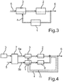
- FIG. 3 is a block diagram of a control system 15 (FIG. Fig. 5 ) according to an embodiment of the invention for a Schubrekuperation.
- An engine control unit 3 receives as input 5, for example, information about the position of an accelerator pedal or for example also about settings of a distance control.
- the engine control unit 3 can, based on this information, but possibly also independently with the aid of other parameters, the electric machine 2 control so that it provides an electrical braking torque. This will change an output variable 6 relating to the speed of the motor vehicle and lead to a recuperation of the kinetic energy of the motor vehicle.
- the engine control unit 3 can thus independently initiate recuperation in the present example.
- the vehicle dynamics module 1 whose task it is just to preserve the stability of the motor vehicle, instruct the engine control unit 3 to reduce or limit the recuperated power.
- the vehicle dynamics module 1 therefore only has to issue a specific message, so that in principle, for example, a standard component can be used.
- the engine control unit 3, the electric machine 2 and the vehicle dynamics module 1 thus form a first control circuit 4, which receives as input 5 said information from the Abstandsregeltempomat or from the position of the accelerator pedal and has as output 6 a signal size which is a speed of the motor vehicle affected.
- the engine control unit 3 and the electric machine 2 are arranged in a forward branch of the first control loop 4 and the vehicle dynamics module 1 in a backward branch of the first control loop 4.
- the engine control unit 3 assumes a control function in the control loop 4th
- FIG. 3 is a block diagram of another embodiment of the control system 15 (FIG. Fig. 5 ). In the present case, it is tuned to a recuperation both in thrust and in braking operation.
- the first control circuit 4 which as in the Fig. 3 an engine control unit 3 an electric machine 2 and a vehicle dynamics module 1 includes, here is a second control loop 11 and a brake booster 7 is provided.
- the brake booster 7 receives in the present example of the engine control unit 3 information regarding. A maximum available electric braking torque.
- an information about the brake pedal as input 5 of the brake booster 7 is a braking request of the driver.
- the brake booster 7 compares the desired braking torque in the illustrated embodiment with the available electric braking torque and decides how much braking torque is provided electrically, so leading to recuperation , And how much braking torque is provided as a hydraulic braking torque to the vehicle.
- the electric braking torque is represented by the input variable 5a of the first control loop 4 and the hydraulic braking torque by the input variable 5b of the second control loop 11. It can also be connected to other modules, such as a hydraulic accumulator 12 ( Fig. 5 ) for brake fluid. For example, adding or removing brake fluid can provide additional functions such as keeping forces and paths constant take place on the brake pedal regardless of the respective electrically and hydraulically delivered braking torque.
- the first control loop 4 in the figure shown is identical to that in FIG Fig. 3 shown control circuit 4, which performs there as here a Schubrekuperation.
- a second control circuit 11 is provided in the present embodiment of the control system. This is formed by the vehicle dynamics module 1 and by this controlled wheel brakes 8. Input 5b of this second control circuit 11 is information about the brake torque to be provided hydraulically, which is requested by the brake booster 7 in the present example.
- the two control circuits 4 and 11 provide a common output variable 6, which relates to the speed or acceleration of the motor vehicle.
- Both the vehicle dynamics module 1 and the brakes 8 are arranged here in a forward branch of the second control loop 11.
- the vehicle dynamics module 1 takes over here in both control circuits 4 and 11 only in case of a possible destabilization of the motor vehicle a regulatory function.
- this information is provided as input 5 to the brake booster 7 available.
- This compares the desired braking torque with the available electric braking torque.
- the information about the available electric braking torque receives the brake booster 7 in the present case continuously, but it is also a discretized flow of information possible.
- the brake booster 7 then divides the desired braking torque into an electrical and a hydraulic component. This division can be both absolute and relative.
- a pedal force or Pedalwegkompensation is performed by the brake booster 7 in the case of a non-zero electrical braking torque. This has the goal that the forces and paths on the brake pedal are always the same, regardless of whether the electric machine 2 or via the wheel brakes 8 is delayed.
- the engine control unit 3 will simultaneously instruct the electric machine 2 to apply an electric braking torque and the vehicle dynamics module 1 instruct the wheel brakes 8 to build up a hydraulic braking torque. These two braking moments work together and thus realize the total braking torque desired by the driver. If this total braking torque now jeopardizes, for example, the stability of the motor vehicle, then this is detected by the vehicle dynamics module 1, which is precisely designed to stabilize the motor vehicle. As a result, the vehicle dynamics module 1 will reduce the total braking torque, preferably individually at the individual wheels. This can be done on the one hand via a reduction of the provided by the wheel brakes 8 hydraulic braking torque, or on the other hand via an instruction to the engine control unit 3 to reduce the electric braking torque. For an effective recuperation operation, it is advantageous to first reduce the hydraulic braking torque. This ensures maximum recuperation performance during braking operation.
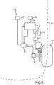
- Fig. 5 a schematic representation of another embodiment of the control system 15 is shown.
- the control system 15 is arranged here in a motor vehicle 16.
- a detail is shown, so that only one wheel 17 of the motor vehicle 16 is shown, however, additional wheels can be coupled to the system 15, for example via more wheel brakes 8 or electric machines 2.
- the wheel 17th provided with a wheel brake 8 and an electric machine 2.
- the electric machine 2 receives control signals from the engine control unit 3. This in turn receives signals from an accelerator pedal 13, the vehicle dynamics module 1 and the brake booster 7.
- the engine control unit 3 transmits information about a deliverable electric braking torque of the electric machine 2 to the brake booster 7.
- Die Radbremse 8 is hydraulically coupled to the vehicle dynamics module 1 in the present example via a hydraulic brake system 18. This in turn is hydraulically coupled via the hydraulic brake system 18 to the brake booster 7 and an active memory 12.
- the brake booster 7 is in turn hydraulically connected to a brake pedal 14 via the hydraulic brake system 18.
- a mechanical penetration of the brake pedal 14 to the wheel brake 8 is ensured by the hydraulic brake system 18.
- the motor vehicle 16 is now in a driving operation, for example, the driver will go from the gas pedal 13 in a certain situation. If an electric braking torque is available, the engine control unit 3 will then signal the electric machine to build up such an electric braking torque. As a result, electrical power is recuperated. If this recuperation due to prevailing conditions, such as external environmental influences endanger the stability of the motor vehicle 16, the vehicle dynamics module 1 will instruct the engine control unit 3 to reduce the recuperation or to prevent. If the driver of the motor vehicle 16 in the meantime want to further slow down the vehicle, he will press a brake pedal 14. Thus, the brake booster 7 is activated. If, for example, the brake pedal 14 has been actuated only slightly, then the requested braking torque may possibly be applied by the electric recuperation alone. This can decide the brake booster 7, since it is informed by the engine control unit 3 about the recoverable electric braking torque. Thus, the brake booster 7
Landscapes
- Engineering & Computer Science (AREA)
- Transportation (AREA)
- Mechanical Engineering (AREA)
- Chemical & Material Sciences (AREA)
- Combustion & Propulsion (AREA)
- Automation & Control Theory (AREA)
- Regulating Braking Force (AREA)
- Electric Propulsion And Braking For Vehicles (AREA)
Description
- Die Erfindung betrifft ein Steuersystem zum Betreiben eines Kraftfahrzeugs gemäß dem Oberbegriff von Patentanspruch 1. Sie betrifft darüber hinaus ein Verfahren zum Betreiben eines mit einem solchen Steuersystem ausgestatteten Kraftfahrzeugs.
- Hybrid- und Elektrofahrzeuge haben mindestens eine elektrische Maschine im Antriebsstrang integriert. Diese elektrische Maschine kann in einem Generatorbetrieb in Abhängigkeit der Drehzahl und des Ladezustands der Batterie ein Bremsmoment an zumindest einem zugeordnetem Rad erzeugen. Verzögerungsschwankungen der elektrischen Maschine werden hier entsprechend gesetzlicher Vorschriften von einer konventionellen hydraulischen Bremsanlage automatisch ausgeglichen. Ein Wechsel des elektrischen und hydraulischen Verzögerungsanteils während einer Bremsung wird Brake Blending, also Bremsen-Blenden, genannt. Ein Ziel hierbei ist, dass die Kräfte und Wege am Bremspedal immer gleich sind, unabhängig davon, ob elektrisch oder über das konventionelle Bremssystem verzögert wird. Im Stand der Technik erfolgt die Koordination von elektrischem und hydraulischem Verzögerungsanteil über ein zusätzliches Bauteil, nämlich einer zentralen Steuereinheit. Diese Steuereinheit ist im Allgemeinen einem Fahrdynamikregelungsmodul zugeordnet, d.h. in dem gleichen Gehäuse angeordnet und elektrisch mit dem Fahrdynamikregelungsmodul gekoppelt, wodurch das Fahrdynamikmodul baulich und elektrisch, also in seiner Logikfunktion, speziell an die zentrale Steuereinheit angepasst werden muss oder alternativ eine an das entsprechende Fahrdynamikmodul angepasste Steuereinheit verbaut werden muss. Die Verwendung von Standardbauteilen ist also ohne weiteres nicht möglich.
- So wird beispielsweise in der
US 5,511,859 eine Methode beschrieben, bei der ein zentrales Bremskontrollelement einen Bremswunsch eines Fahrers, einzelne Drehzahlen von Fahrzeugrädern und das verfügbare elektrische Bremsmoment erfasst.
Das zentrale Bremskontrollelement regelt dann eine Aufteilung in elektrisch und hydraulisch erbrachten Verzögerungsanteil. Gleichzeitig übernimmt es die Funktion eines Antiblockiersystems. - Die
DE 10 2005 059 373 A1 beschreibt ein Verfahren zur Steuerung eines Bremssystems eines Kraftfahrzeugs, bei welchem ebenfalls ein Brake Blen ding erfolgt. Hierbei wird ein situationsabhängig ermitteltes Gesamtsollbremsmoment zunächst rein elektrisch über einen Generator erbracht, und hydraulische Bremsen werden zugeschaltet, wenn das Gesamtsollbremsmoment das Bremsmoment des Generators um eine vorgegebenen maximale Bremsmomentdifferenz überschreitet. - In der
US 6,155,365 ist ein Bremssystem beschrieben, bei welchem eine Kontrolleinheit ein angefordertes Bremsmoment mit einem verfügbaren elektrischen Bremsmoment vergleicht und elektrisch bzw. hydraulisch erbrachtes Bremsmoment entsprechend steuert. - Die
WO 2013 045 584 A1 beschreibt ein rekuperatives Bremssystem für ein Kraftfahrzeug mit einer Reibungsbremsensteuereinrichtung, einem Zustandsbeobachter, einer Bremsschlupfregelung sowie einer Momentenverteilung. Mit dem rekuperativen Bremssystem ist ein elektrischer Antrieb mit einer Elektroantriebsteuereinrichtung gekoppelt, wobei eine zugehörige elektrische Maschine zumindest zeitweise als Generator angesteuert werden kann. Bei einem Bremsvorgang wird eine Verzögerungsanforderung als Eingangssignal für das rekuperative Bremssystem genutzt, indem die Bremsschlupfregelung aus der Verzögerungsanforderung Sollbremsmomente für die einzelnen Räder ermittelt. - Die
DE 10 2011 004 140 A1 offenbart ein Bremssystem für ein Kraftfahrzeug mit einem Bremskraftverstärker zur Verstärkung einer Bremskraft und einer Bremsdruckbereitstellungseinrichtung zur Bereitstellung von Bremsdruck mittels eines Bremsmediums. - Die vorliegende Erfindung hat zur Aufgabe, ein Steuersystem zum Betreiben eines Kraftfahrzeugs bereitzustellen, welches eine effiziente Rekuperation bei niedrigen Kosten, Entwicklungsaufwand und Gewicht ermöglicht. Die Erfindung hat ebenfalls zur Aufgabe, ein Verfahren zum Betreiben eines Kraftfahrzeugs mit einem solchen Steuersystem bereitzustellen.
- Diese Aufgabe wird erfindungsgemäß durch ein Steuersystem bzw. ein Verfahren gemäß den unabhängigen Patentansprüchen gelöst. Vorteilhafte Ausführungen der Erfindung sind Gegenstand der abhängigen Patentansprüche, der Beschreibung und der Figuren.
- Um eine besonders effektive Rekuperation zu erzielen, sind in einem erfindungsgemäßen Steuersystem zum Betreiben eines Kraftfahrzeugs zunächst drei Elemente vorgesehen: Ein Fahrdynamikmodul, welches ausgelegt ist, das Kraftfahrzeug zu stabilisieren, eine elektrische Maschine, die in einem Rekuperationsmodus betreibbar ist, in welchem ein veränderlicher Betrag an elektrischer Leistung rekuperierbar ist, und ein Motorsteuergerät, welches ausgelegt ist, die elektrische Maschine in dem Rekuperationsmodus anzusteuern.
- Mittels des Motorsteuergeräts wird also von der elektrischen Maschine wiedergewonnene elektrische Leistung, also die elektrische Leistung, die durch die elektrische Maschine dem Kraftfahrzeug wieder zugeführt wird, gesteuert. Hierbei ist das Motorsteuergerät und die elektrische Maschine in einem Vorwärtszweig eines ersten Regelkreises angeordnet, wobei eine Eingangsgröße des ersten Regelkreises, und damit des Motorsteuergeräts, mindestens eine die Geschwindigkeit des Kraftfahrzeugs beeinflussende Signalgröße darstellt. Eine solche Signalgröße ist insbesondere eine Information über eine Gaspedalstellung oder eine sonstige Signalgröße, welche eine beizubehaltende oder zu verändernde Geschwindigkeit repräsentiert, beispielsweise von einem Abstandsregeltempomat stammend. Insbesondere können also auch mehrere Signalgrößen, welche die Geschwindigkeit des Kraftfahrzeugs beeinflussen, Eingangsgrößen des ersten Regelkreises darstellen.
- Im Gegensatz zum Stand der Technik, und damit Wesentlich für die Erfindung, ist, dass das Fahrdynamikmodul in einem Rückwärtszweig des ersten Regelkreises angeordnet ist. Die Erfindung hat so gegenüber dem Stand der Technik eine ganze Reihe von Vorteilen: Zum einen kann so das Motorsteuergerät selbständig einen Rekuperationsmodus der elektrischen Maschine einleiten und steuern. Das heißt, das Motorsteuergerät kann allein aufgrund der ihm vorliegenden Daten ohne weitere Kommunikation und Rückfrage bei einer übergeordneten Einheit, wie beispielsweise im Stand der Technik bei dem Fahrdynamikmodul nebst zugeordneter zentraler Steuereinheit, die elektrische Maschine veranlassen, elektrische Energie zu rekuperieren. Somit kann besonders flexibel und agil, also effizient Energie rekuperiert werden. Auch ist für die Rekuperation so keine zusätzliche Steuereinheit mehr erforderlich. Das hat nicht nur eine Gewichtsersparnis zur Folge, sondern macht auch die oben erwähnten Hardware- und Logikanpassungen der Geräte untereinander obsolet und vereinfacht allgemein die Architektur des Systems und reduziert somit Entwicklungskosten und Störanfälligkeit. Das vorgestellte System kann zudem kostengünstig mit Standard-Komponenten realisiert werden, welche hierfür lediglich in ihrer Steuerung und/oder Kommunikation angepasst werden müssen. Ferner muss das Fahrdynamikmodul so nur bei einer eventuell durch den Rekuperationsmodus erfolgenden Destabilisierung des Kraftfahrzeugs aktiv eingreifen. Somit werden die Kommunikationswege nur in diesem Fall belastet und Ressourcen in diesem Bauteil geschont.
- Durch die Ressourceneinsparung innerhalb des Bauteils ist eine kostensparende Bauteilgleichheit z.B. mit einem Projekt mit ausschließlich konventionellem, hydraulischem Bremssystem möglich. Beide Elemente, nämlich das Motorsteuergerät und auch das Fahrdynamikmodul, übernehmen so in dem ersten Regelkreis genau die Aufgaben, auf die sie baulich ausgelegt sind: Das Fahrdynamikmodul wird aktiv, sobald die Stabilität des Kraftfahrzeugs geregelt werden muss, und das Motorsteuergerät wird aktiv, sobald die Geschwindigkeit des Kraftfahrzeugs beeinflusst werden soll.
- In einer vorteilhaften Ausführungsform der Erfindung ist es vorgesehen, dass der erste Regelkreis ausgebildet ist, in einem Betriebsmodus betrieben zu werden, in dem durch ein Verändern der im Rekuperationsmodus der elektrischen Maschine zurückgewonnenen Leistung eine Ausgangsgröße des ersten Regelkreises geregelt wird. Das hat den Vorteil, dass so situationsabhängig die maximale Rekuperationsleistung, welche die Stabilität des Kraftfahrzeugs nicht gefährdet, erbracht werden kann.
- Insbesondere ist vorgesehen, dass vor dem Vorwärtszweig des ersten Regelkreises ein Bremskraftverstärker angeordnet ist.
- Dieser Bremskraftverstärker ist dann vorzugsweise dazu ausgelegt, dem Motorsteuergerät eine Eingangsgröße zur Verfügung zu stellen, welche zumindest einen Teil eines von einem Fahrer gewünschten Bremsmoments repräsentiert. Das hat den Vorteil, dass auch eine Rekuperation im Bremsbetrieb erfolgen kann, also eine gezielte, durch den Fahrer initiierte Rekuperation stattfinden kann.
- In einer weiteren Ausführungsform der Erfindung ist vorgesehen, dass das Motorsteuergerät ausgelegt ist, eine Information über ein mittels des Rekuperationsmodus der elektrischen Maschine erzielbares elektrisches Bremsmoment an den Bremskraftverstärker zu übermitteln. Das hat den Vorteil, dass der Bremskraftverstärker so nicht ein elektrisches Bremsmoment von dem Motorsteuergerät anfordern wird, welches von diesem nicht erbringbar ist. Somit wird ein aufwändiges und möglicherweise verzögertes Nachsteuern vermieden.
- Es kann ferner vorgesehen sein, dass der Bremskraftverstärker ausgelegt ist, auch dem Fahrdynamikmodul eine Eingangsgröße zur Verfügung zu stellen, welche zumindest einen Teil eines von einem Fahrer gewünschten Bremsmoments repräsentiert. Das hat den Vorteil, dass das Fahrdynamikmodul einen Bremswunsch des Fahrers an die Radbremsen weiterleiten kann sowie den Bremswunsch bei einem Stabilisieren des Kraftfahrzeugs und bei einem Bremswunsch des Fahrers das Stabilisieren des Kraftfahrzeugs mit berücksichtigen kann.
- In einer bevorzugten Ausführungsform ist das Fahrdynamikmodul in einem Vorwärtszweig eines zweiten Regelkreises angeordnet, wobei eine Eingangsgröße des zweiten Regelkreises zumindest ein Teil eines von einem Fahrer gewünschten Bremsmoments repräsentiert. Insbesondere dient der zweite Regelkreis dem Regeln eines über Radbremsen erbrachten hydraulischen Bremsmoments. Das hat den Vorteil, dass das Fahrdynamikmodul einen Teil des von einem Fahrer gewünschten Bremsmoments, insbesondere das hydraulische Bremsmoment, regeln kann.
- In einer vorteilhaften Ausführungsform der Erfindung ist der Rekuperationsmodus der elektrischen Maschine und auch das Motorsteuergerät derart ausgebildet, dass im Rekuperationsmodus nicht zwischen einer selbständigen, unmittelbaren Ansteuerung durch das Motorsteuergerät und einer durch den Bremskraftverstärker initiierten, mittelbaren Ansteuerung unterschieden wird. Es ist also über eine selbständige, unmittelbare Ansteuerung der elektrischen Maschine durch das Motorsteuergerät ein im Wesentlichen gleich hoher Betrag an elektrischer Leistung rekuperierbar, wie über eine durch den Bremskraftverstärker initiierte, mittelbare Ansteuerung der elektrischen Maschine. Das Motorsteuergerät kann ohne eine aktive Ansteuerung durch den Bremskraftverstärker im Wesentlichen genauso viel elektrische Leistung wiedergewinnen, wie mit einer Ansteuerung durch den Bremskraftverstärker. Das hat den Vorteil, dass so eine besonders effektive Schubrekuperation realisiert wird, bei welcher auch ohne ein Betätigen des Bremskraftverstärkers eine besonders hohe elektrische Leistung rekuperiert werden kann.
- In einer besonders vorteilhaften Ausführungsform ist vorgesehen, dass der Bremskraftverstärker ausgelegt ist, ein von einem Fahrer gewünschtes Bremsmoment aufzuteilen in einen elektrischen Bremsmomentanteil, welcher von einer in den ersten Regelkreis geleiteten Eingangsgröße repräsentiert ist, und in einen hydraulischen Bremsmomentanteil, welcher von einer in den zweiten Regelkreis geleiteten Eingangsgröße repräsentiert ist. Das hat den Vorteil, dass ohne zusätzliche Bauteile eine effektive Rekuperation sowohl in einem Schubbetrieb als auch in einem Bremsbetrieb möglich ist. Für die bei einer Rekuperation aktiven Bauteile wird so nicht zwischen Schub- und Bremsrekuperation unterschieden. Insbesondere sind so Standardfahrdynamikmodule und Standardmotorsteuergeräte verwendbar, welche nur leicht modifiziert werden müssen. Somit ist ein kostengünstigeres und leichteres System realisiert, welches mit weniger Bauteilen die Funktionalität üblicher Systeme zur Rekuperation erbringt.
- Insbesondere ist hier vorgesehen, dass der Bremskraftverstärker mit dem Fahrdynamikmodul hydraulisch gekoppelt ist. Das hat den Vorteil, dass ein hydraulisch-mechanischer Durchgriff auf die Radbremsen gewährleistet ist. Somit ist es möglich, die gesetzlichen Auflagen zu Bremsanlagen kostengünstig zu realisieren.
- Bevorzugt ist vorgesehen, dass der Bremskraftverstärker und das Fahrdynamikmodul in ein hydraulisches Bremssystem integriert sind, welches insbesondere auch die Radbremsen umfasst, und in das Bremssystem ein aktiver Flüssigkeitsspeicher integriert ist. Insbesondere kann der aktive Speicher hier zwischen dem Bremskraftverstärker und dem Fahrdynamikmodul eingekoppelt sein. Mit diesem Flüssigkeitsspeicher ist eine hydraulische Volumenkompensation erbringbar. Insbesondere kann so das Bremsflüssigkeitsvolumen, welches der über die elektrische Maschine erbrachten Verzögerung entspricht, kompensiert werden. Das hat den Vorteil, dass die Wege und/oder Positionen am Bremspedal immer der sich einstellenden Fahrzeugverzögerung entsprechen.
- Insbesondere ist hier vorgesehen, dass der Bremskraftverstärker dazu ausgelegt ist, eine Pedalkraftkompensation durchzuführen, welche dem Teil des von dem Fahrer gewünschten Bremsmoments entspricht, der durch die vom Bremskraftverstärker dem Motorsteuergerät zur Verfügung gestellten Eingangsgröße repräsentiert ist. Das hat den Vorteil, dass die Kraft am Bremspedal immer der tatsächlichen Gesamtverzögerung des Kraftfahrzeugs entspricht, unabhängig davon, wie diese Gesamtverzögerung auf ein elektrisches und hydraulisches Verzögerungsmoment aufgeteilt ist.
- Die Erfindung betrifft auch ein Verfahren zum Betreiben eines Kraftfahrzeugs mit einem Steuersystem, welches ein Fahrdynamikmodul, das das Kraftfahrzeug stabilisiert, eine in einem Rekuperationsmodus betreibbare elektrische Maschine, sowie ein Motorsteuergerät, welches die elektrische Maschine in dem Rekuperationsmodus ansteuert, umfasst. Dabei ist das Motorsteuergerät und die elektrische Maschine in einem Vorwärtszweig eines ersten Regelkreises angeordnet und das Motorsteuergerät erhält als Eingangsgröße des ersten Regelkreises mindestens eine die Geschwindigkeit des Kraftfahrzeugs beeinflussende Signalgröße, wobei ein Rückkoppeln einer Ausgangsgröße des ersten Regelkreises über das in einem Rückwärtszweig des ersten Regelkreises angeordnete Fahrdynamikmodul erfolgt.
- Die mit Bezug auf das erfindungsgemäße Steuersystem vorgestellten bevorzugten Ausführungsformen und deren Vorteile gelten entsprechend für das erfindungsgemäße Verfahren.
- Weitere Merkmale der Erfindung ergeben sich aus den Ansprüchen, den Figuren und der Figurenbeschreibung. Alle vorstehend in der Beschreibung genannten Merkmale und Merkmalskombinationen sowie die nachfolgend in der Figurenbeschreibung genannten und/oder in den Figuren alleine gezeigten Merkmale und Merkmalskombinationen sind nicht nur in der jeweils angegebenen Kombination sondern auch in anderen Kombinationen oder aber in Alleinstellung verwendbar.
- Ein Ausführungsbeispiel der Erfindung wird nachfolgend anhand der Figuren erläutert. Dabei zeigen:
- Fig. 1
- ein Blockschaltbild eines Steuersystems nach dem Stand der Technik für einen Schubrekuperationsbetrieb;
- Fig. 2
- ein Blockschaltbild eines Steuersystems nach dem Stand der Technik für einen Bremsrekuperationsbetrieb;
- Fig. 3
- ein Blockschaltbild eines Steuersystems gemäß einer Ausführungsform der Erfindung für einen Schubrekuperationsbetrieb;
- Fig. 4
- ein Blockschaltbild eines Steuersystems gemäß einer Ausführungsform der Erfindung für einen Schub- und Bremsrekuperationsbetrieb; sowie
- Fig. 5
- eine schematische Darstellung eines Steuersystems gemäß einer Ausführungsform der Erfindung.
- In den Figuren werden gleiche oder funktionsgleiche Elemente mit den gleichen Bezugszeichen versehen.
- In
Fig. 1 ist ein Blockschaltbild eines Steuersystems nach dem Stand der Technik für einen Schubrekuperationsbetrieb dargestellt. Hierbei bietet ein Motorsteuergerät 3 einem Fahrdynamikmodul 1 ein elektrisches Bremsmoment an. Das Motorsteuergerät 3 kann dies selbständig anbieten oder auf Grund einer Eingangsgröße 5, wie beispielsweise ein von-dem-Gas-gehen eines Fahrers eines Kraftwagens sie darstellt. Das Fahrdynamikmodul 1 wird ausgehend von dem Motorsteuergerät 3 angebotenen elektrischen Bremsmoment sowie weiteren, die Stabilität des Kraftfahrzeugs betreffenden, Parametern das Motorsteuergerät 3 anweisen, ein elektrisches Bremsmoment zu erzeugen. Das Motorsteuergerät 3 wird in Folge die elektrische Maschine 2 ansteuern um das elektrische Bremsmoment zu erzielen. Die Ausgangsgröße 6 des Steuersystems repräsentiert dann eine Veränderung der Geschwindigkeit bzw. Beschleunigung des Kraftfahrzeugs. Beispielsweise über Drehzahlsensoren an den Rädern erhält das Fahrdynamikmodul 1 eine Rückkopplung betreffend der Geschwindigkeit oder Beschleunigung des Kraftfahrzeugs und kann das Motorsteuergerät 3 bzw. das elektrische Bremsmoment entsprechend nachregeln. - In
Fig. 2 ist ein Blockschaltbild eines Steuersystems nach dem Stand der Technik für einen Bremsrekuperationsmodus dargestellt. Das Fahrdynamikmodul 1 erhält hier wie inFig. 1 von dem Motorsteuergerät 3 die Information, dass ein elektrisches Bremsmoment zur Verfügung steht. Gleichzeitig wird Information über ein von einem Fahrer des Kraftfahrzeugs erwünschtes Bremsmoment als Eingangsgröße 5 über einen Bremskraftverstärker 7 an das Fahrdynamikmodul weitergeleitet. Das Fahrdynamikmodul 1 kann nun, möglicherweise auch unter Verwendung weiterer Parameter, das von dem Fahrer erwünschte Bremsmoment in ein elektrisch zu erbringendes Bremsmoment und in ein hydraulisch zu erbringendes Bremsmoment aufteilen. Entsprechend werden dann das Motorsteuergerät 3 sowie Radbremsen 8 von dem Fahrdynamikmodul 1 angesteuert. - In Folge erbringt die elektrische Maschine 2 ein elektrisches Bremsmoment und die Radbremsen 8 ein üblicherweise hydraulisches Bremsmoment, welche in Vereinigung das gewünschte Bremsmoment ergeben und so das Kraftfahrzeug verzögern. Somit wird die Ausgangsgröße 6, welche Geschwindigkeit oder Beschleunigung des Kraftfahrzeugs repräsentiert, durch die Eingangsgröße 5, also eine Information über das gewünschte Bremsmoment, verändert. Wie in
Fig. 1 erhält das Fahrdynamikmodul 1, beispielsweise über Drehzahlsensoren, eine Rückmeldung über die erfolgte Veränderung der Ausgangsgröße 6 und kann somit die Radbremsen 8 und das Motorsteuergerät 3 regeln. - In
Fig. 3 ist ein Blockschaltbild eines Steuersystems 15 (Fig. 5 ) gemäß einer Ausführungsform der Erfindung für eine Schubrekuperation dargestellt. Ein Motorsteuergerät 3 erhält als Eingangsgröße 5 beispielsweise Information über die Position eines Gaspedals oder beispielsweise auch über Einstellungen eines Abstandsregeltempomats. Das Motorsteuergerät 3 kann auf Grundlage dieser Information, möglicherweise aber auch selbständig unter Zuhilfenahme anderer Parameter, die elektrische Maschine 2 ansteuern, damit diese ein elektrisches Bremsmoment erbringt. Dieses wird eine die Geschwindigkeit des Kraftfahrzeugs betreffende Ausgangsgröße 6 verändern und zu einer Rekuperation der Bewegungsenergie des Kraftfahrzeugs führen. Das Motorsteuergerät 3 kann im vorliegenden Beispiel also selbständig eine Rekuperation einleiten. Hierbei ist zu beachten, dass je nach dem Betrag der rekuperierten Leistung unter Umständen die Stabilität des Kraftfahrzeugs gefährdet werden könnte. Sollte dies der Fall sein, wird das Fahrdynamikmodul 1, dessen Aufgabe es ja gerade ist, die Stabilität des Kraftfahrzeugs zu bewahren, das Motorsteuergerät 3 anweisen, die rekuperierte Leistung zu vermindern bzw. zu beschränken. Hierfür muss das Fahrdynamikmodul 1 also lediglich eine spezifische Meldung ausgeben, so dass hier grundsätzlich z.B. ein Standardbauteil zur Verwendung kommen kann. Insgesamt bilden das Motorsteuergerät 3, die elektrische Maschine 2 und das Fahrdynamikmodul 1 also einen ersten Regelkreis 4, der als Eingangsgröße 5 besagte Information aus dem Abstandsregeltempomat bzw. aus der Position des Gaspedals erhält und als Ausgangsgröße 6 eine Signalgröße aufweist, die eine Geschwindigkeit des Kraftfahrzeugs beeinflusst. Wichtig ist hier, dass das Motorsteuergerät 3 und die elektrische Maschine 2 in einem Vorwärtszweig des ersten Regelkreises 4 und das Fahrdynamikmodul 1 in einem Rückwärtszweig des ersten Regelkreises 4 angeordnet sind.
Damit übernimmt das Motorsteuergerät 3 eine Regelfunktion in dem Regelkreis 4. - In
Fig. 4 ist ein Blockschaltbild einer weiteren Ausführungsform des Steuersystems 15 (Fig. 5 ) dargestellt. Im vorliegenden Fall ist es auf eine Rekuperation sowohl im Schub- als auch im Bremsbetrieb abgestimmt. Zusätzlich zu dem ersten Regelkreis 4, welcher wie in derFig. 3 ein Motorsteuergerät 3, eine elektrische Maschine 2 und ein Fahrdynamikmodul 1 umfasst, ist hier noch ein zweiter Regelkreis 11 sowie ein Bremskraftverstärker 7 vorgesehen. Der Bremskraftverstärker 7 erhält im vorliegenden Beispiel von dem Motorsteuergerät 3 eine Information bzgl. eines maximal verfügbaren elektrischen Bremsmomentes. Gleichzeitig stellt z.B. eine Information über das Bremspedal als Eingangsgröße 5 des Bremskraftverstärkers 7 einen Bremswunsch des Fahrers dar. Der Bremskraftverstärker 7 vergleicht im gezeigten Ausführungsbeispiel das gewünschte Bremsmoment mit dem zur Verfügung stehenden elektrischen Bremsmoment und entscheidet wieviel Bremsmoment elektrisch erbracht wird, also zu einer Rekuperation führt, und wieviel Bremsmoment als hydraulisches Bremsmoment dem Fahrzeug zur Verfügung gestellt wird. Das elektrische Bremsmoment wird von der Eingangsgröße 5a des ersten Regelkreises 4 und das hydraulische Bremsmoment von der Eingangsgröße 5b des zweiten Regelkreises 11 repräsentiert. Es können hier auch weitere Module angeschlossen sein, wie beispielsweise ein hydraulischer Speicher 12 (Fig. 5 ) für Bremsflüssigkeit. So können ein Zu- oder Abführen von Bremsflüssigkeit Zusatzfunktionen wie ein Konstanthalten von Kräften und Wegen am Bremspedal unabhängig von den jeweils elektrisch und hydraulisch erbrachten Bremsmomenten erfolgen. Dies dient sowohl dem Komfort als auch der Sicherheit, da so für den Fahrer in einer Bremssignalposition stets gleichbleibende Kräfte wahrzunehmen sind. Der erste Regelkreis 4 in der gezeigten Figur ist identisch zu dem inFig. 3 gezeigten Regelkreis 4, welcher dort wie hier eine Schubrekuperation durchführt. Zusätzlich zu dem Regelkreis 4 ist in der vorliegenden Ausführung des Steuersystems ein zweiter Regelkreis 11 vorhanden. Dieser wird von dem Fahrdynamikmodul 1 und von diesem angesteuerten Radbremsen 8 gebildet. Eingangsgröße 5b von diesem zweiten Regelkreis 11 ist eine Information über das hydraulisch zu erbringende Bremsmoment, welches im vorliegenden Beispiel durch den Bremskraftverstärker 7 angefordert wird. - Nachdem sowohl die Radbremsen 8 als auch die elektrische Maschine 2 einen Einfluss auf die Geschwindigkeit bzw. die Beschleunigung des Kraftfahrzeugs haben, liefern die beiden Regelkreise 4 und 11 eine gemeinsame Ausgangsgröße 6, welche sich auf die Geschwindigkeit bzw. Beschleunigung des Kraftfahrzeugs bezieht. Sowohl das Fahrdynamikmodul 1 als auch die Bremsen 8 sind hier in einem Vorwärtszweig des zweiten Regelkreises 11 angeordnet. Das Fahrdynamikmodul 1 übernimmt hier also in beiden Regelkreisen 4 und 11 nur bei einer eventuellen Destabilisierung des Kraftfahrzeugs eine regelnde Funktion.
- Betätigt nun beispielsweise der Fahrer des Kraftfahrzeugs ein Bremspedal, so wird diese Information als Eingangsgröße 5 dem Bremskraftverstärker 7 zur Verfügung gestellt. Dieser vergleicht das gewünschte Bremsmoment mit dem zur Verfügung stehenden elektrischen Bremsmoment. Die Information über das zur Verfügung stehende elektrische Bremsmoment erhält der Bremskraftverstärker 7 im vorliegenden Fall kontinuierlich, es ist jedoch auch ein diskretisierter Informationsfluss möglich. Der Bremskraftverstärker 7 teilt dann das gewünschte Bremsmoment in einen elektrischen und einen hydraulischen Anteil auf. Diese Aufteilung kann sowohl absolut als auch relativ erfolgen. Bevorzugt wird durch den Bremskraftverstärker 7 im Falle eines von Null verschiedenen elektrischen Bremsmoments eine Pedalkraft- bzw. Pedalwegkompensation durchgeführt. Das hat zum Ziel, dass die Kräfte und Wege am Bremspedal immer gleich sind, unabhängig davon, ob über die elektrische Maschine 2 oder über die Radbremsen 8 verzögert wird. In Folge der Aufteilung wird gleichzeitig das Motorsteuergerät 3 die elektrische Maschine 2 anweisen, ein elektrisches Bremsmoment aufzubringen und das Fahrdynamikmodul 1 die Radbremsen 8 dazu anweisen, ein hydraulisches Bremsmoment aufzubauen. Diese beiden Bremsmomente wirken zusammen und realisieren so das vom Fahrer gewünschte Gesamtbremsmoment. Sollte dieses Gesamtbremsmoment nun beispielsweise die Stabilität des Kraftfahrzeugs gefährden, so wird dies von dem Fahrdynamikmodul 1, welches ja genau dazu ausgelegt ist, das Kraftfahrzeug zu stabilisieren, detektiert. In Folge wird das Fahrdynamikmodul 1 das Gesamtbremsmoment, bevorzugt individuell an den einzelnen Rädern, reduzieren. Dies kann zum einen über eine Reduktion des von den Radbremsen 8 erbrachten hydraulischen Bremsmoments erfolgen, oder zum anderen über ein Anweisung an das Motorsteuergerät 3, das elektrische Bremsmoment zu reduzieren.
Für einen effektiven Rekuperationsbetrieb ist es vorteilhaft, zunächst das hydraulische Bremsmoment zu reduzieren. Damit ist im Bremsbetrieb stets eine maximale Rekuperationsleistung gewährleistet. - In
Fig. 5 ist eine schematische Darstellung einer weiteren Ausführungsform des Steuersystems 15 dargestellt. Das Steuersystem 15 ist hier in einem Kraftfahrzeug 16 angeordnet. Von dem Kraftfahrzeug 16 ist ein Ausschnitt gezeigt, so dass lediglich ein Rad 17 des Kraftfahrzeugs 16 gezeigt ist, jedoch können auch zusätzliche Räder an das System 15 gekoppelt werden, beispielsweise über weitere Radbremsen 8 oder elektrische Maschinen 2. Im gezeigten Ausschnitt ist das Rad 17 mit einer Radbremse 8 und einer elektrischen Maschine 2 versehen. Die elektrische Maschine 2 empfängt Steuersignale von dem Motorsteuergerät 3. Dieses empfängt seinerseits Signale von einem Gaspedal 13, dem Fahrdynamikmodul 1 und dem Bremskraftverstärker 7. Das Motorsteuergerät 3 übermittelt Information über ein erbringbares elektrisches Bremsmoment der elektrischen Maschine 2 an dem Bremskraftverstärker 7. Die Radbremse 8 ist im vorliegenden Beispiel über ein hydraulisches Bremssystem 18 hydraulisch an das Fahrdynamikmodul 1 gekoppelt. Dieses ist seinerseits wiederum über das hydraulische Bremssystem 18 hydraulisch an den Bremskraftverstärker 7 und einen aktiven Speicher 12 gekoppelt. Der Bremskraftverstärker 7 ist seinerseits über das hydraulische Bremssystem 18 hydraulisch mit einem Bremspedal 14 verbunden. Somit ist durch das hydraulische Bremssystem 18 ein mechanischer Durchgriff von dem Bremspedal 14 auf die Radbremse 8 gewährleistet. - Befindet sich das Kraftfahrzeug 16 nun in einem Fahrbetrieb, wird beispielsweise der Fahrer in einer bestimmten Situation vom Gaspedal 13 gehen. Das Motorsteuergerät 3 wird dann, sofern eine elektrisches Bremsmoment verfügbar ist, der elektrischen Maschine signalisieren, ein solches elektrisches Bremsmoment aufzubauen. In Folge wird elektrische Leistung rekuperiert.
Sollte diese Rekuperation aufgrund vorherrschender Bedingungen, wie beispielsweise äußeren Umwelteinflüssen, die Stabilität des Kraftfahrzeugs 16 gefährden, so wird das Fahrdynamikmodul 1 das Motorsteuergerät 3 anweisen, die Rekuperation zu reduzieren bzw. zu unterbinden. Sollte der Fahrer des Kraftfahrzeugs 16 in der Zwischenzeit das Fahrzeug weiter verlangsamen wollen, so wird er ein Bremspedal 14 betätigen. Damit wird auch der Bremskraftverstärker 7 aktiviert. Sollte nun beispielsweise das Bremspedal 14 nur leicht betätigt worden sein, so kann das angeforderte Bremsmoment ggf. durch die elektrische Rekuperation alleine aufgebracht werden.
Dies kann der Bremskraftverstärker 7 entscheiden, da er von dem Motorsteuergerät 3 über das erbringbare elektrische Bremsmoment informiert ist. Somit kann der Bremskraftverstärker 7
Claims (14)
- Steuersystem (15) zum Betreiben eines Kraftfahrzeugs (16) mit- einem Fahrdynamikmodul (1), das ausgelegt ist das Kraftfahrzeug (16) zu stabilisieren,- einer elektrischen Maschine (2), die in einem Rekuperationsmodus betreibbar ist, in dem ein veränderlicher Betrag an elektrischer Leistung rekuperierbar ist, sowie- einem Motorsteuergerät (3), das ausgelegt ist, die elektrische Maschine (2) in dem Rekuperationsmodus anzusteuern,wobei das Motorsteuergerät (3) und die elektrische Maschine (2) in einem Vorwärtszweig eines ersten Regelkreises (4) angeordnet sind,
wobei eine Eingangsgröße des ersten Regelkreises (4) mindestens eine, die Geschwindigkeit des Kraftfahrzeugs beeinflussende, Signalgröße (5) darstellt,
wobei das Fahrdynamikmodul (1) in einem Rückwärtszweig des ersten Regelkreises (4) angeordnet ist,
dadurch gekennzeichnet, dass mittels des Motorsteuergeräts (3) eine von der elektrischen Maschine (2) wiedergewonnene elektrische Leistung, die durch die elektrische Maschine (2) dem Kraftfahrzeug (16) wieder zuführbar ist, regelbar ist. - Steuersystem (15) nach Anspruch 1,
dadurch gekennzeichnet, dass
der erste Regelkreis (4) ausgebildet ist, in einem Betriebsmodus betrieben zu werden, in dem durch ein Verändern der im Rekuperationsmodus der elektrischen Maschine (2) zurückgewonnenen Leistung eine Ausgangsgröße (6) des ersten Regelkreises geregelt wird. - Steuersystem (15) nach einem der vorhergehenden Ansprüche,
dadurch gekennzeichnet, dass- ein Bremskraftverstärker (7) vor dem Vorwärtszweig des ersten Regelkreises (4) angeordnet ist,und der Bremskraftverstärker (7) ausgelegt ist, dem Motorsteuergerät (3) eine Eingangsgröße (5a) zur Verfügung zu stellen, welche zumindest einen Teil eines von einem Fahrer gewünschten Bremsmoments repräsentiert. - Steuersystem (15) nach Anspruch 3,
dadurch gekennzeichnet, dass
das Motorsteuergerät (3) ausgelegt ist, eine Information über ein mittels des Rekuperationsmodus der elektrischen Maschine (2) erzielbares elektrisches Bremsmoment an den Bremskraftverstärker (7) zu übermitteln. - Steuersystem (15) nach einem der Ansprüche 3 bis 4,
dadurch gekennzeichnet, dass
der Bremskraftverstärker (7) ausgelegt ist, auch dem Fahrdynamikmodul (1) eine Eingangsgröße (5b) zur Verfügung zu stellen, welche zumindest einen Teil eines von einem Fahrer gewünschten Bremsmoments repräsentiert. - Steuersystem (15) nach einem der Ansprüche 3 bis 5,
dadurch gekennzeichnet, dass
der Rekuperationsmodus der elektrischen Maschine (2) und auch das Motorsteuergerät (3) derart ausgebildet sind, dass im Rekuperationsmodus nicht zwischen einer selbstständigen, unmittelbaren Ansteuerung der elektrischen Maschine (2) durch das Motorsteuergerät (3) und einer durch den Bremskraftverstärker (7) initiierten, mittelbaren Ansteuerung unterschieden wird. - Steuersystem (15) nach einem der Ansprüche 3 bis 6,
dadurch gekennzeichnet, dass
das Fahrdynamikmodul (1) in einem Vorwärtszweig eines zweiten Regelkreises (11) angeordnet ist, wobei eine Eingangsgröße (5b) des zweiten Regelkreises (11) zumindest einen Teil eines von einem Fahrer gewünschten Bremsmoments repräsentiert. - Steuersystem (15) nach Anspruch 7,
dadurch gekennzeichnet, dass
der Bremskraftverstärker (7) ausgelegt ist, ein von einem Fahrer gewünschtes Bremsmoment aufzuteilen in einen elektrischen Bremsmomentanteil, welcher von einer in den ersten Regelkreis (4) geleiteten Eingangsgröße (5a) repräsentiert ist, und einen hydraulischen Bremsmomentanteil, welcher von einer in den zweiten Regelkreis (11) geleiteten Eingangsgröße (5b) repräsentiert ist. - Steuersystem (15) nach einem der Ansprüche 3 bis 8,
dadurch gekennzeichnet, dass
der Bremskraftverstärker (7) mit dem Fahrdynamikmodul (1) hydraulisch gekoppelt ist. - Steuersystem (15) nach einem der Ansprüche 3 bis 9,
dadurch gekennzeichnet, dass
der Bremskraftverstärker (7) und das Fahrdynamikmodul (1) Bestandteil eines hydraulischen Bremssystems (18) sind und zwischen dem Bremskraftverstärker (7) und dem Fahrdynamikmodul (1) ein aktiver Speicher (12) für Flüssigkeit integriert ist, mittels welchem eine hydraulische Volumenkompensation erbringbar ist. - Steuersystem (15) nach einem der Ansprüche 3 bis 10,
dadurch gekennzeichnet, dass
der Bremskraftverstärker (7) dazu ausgelegt ist, eine Pedalkraftkompensation durchzuführen, welche dem Teil des von dem Fahrer gewünschten Bremsmoments entspricht, der durch die vom Bremskraftverstärker (7) dem Motorsteuergerät (3) zu Verfügung gestellten Eingangsgröße repräsentiert ist. - Verfahren zum Betreiben eines Kraftfahrzeugs (16) mit einem Steuersystem (15), welches- ein Fahrdynamikmodul (1), welches das Kraftfahrzeug (16) stabilisiert,- eine in einem Rekuperationsmodus betreibbare elektrischen Maschine (2), sowie- ein Motorsteuergerät (3), welches die elektrische Maschine (2) in dem Rekuperationsmodus ansteuert, umfasst,wobei das Motorsteuergerät (3) und die elektrische Maschine (2) in einem Vorwärtszweig eines ersten Regelkreises (4) angeordnet sind und
wobei das Motorsteuergerät (3) als Eingangsgröße (5) des ersten Regelkreises (4) mindestens eine die Geschwindigkeit des Kraftfahrzeugs beeinflussende Signalgröße (5) erhält, mit einem
Rückkoppeln einer Ausgangsgröße (6) des ersten Regelkreises (4) über das in einem Rückwärtszweig des ersten Regelkreises (4) angeordnete Fahrdynamikmodul (1) dadurch gekennzeichnet, dass
mittels des Motorsteuergeräts (3) eine von der elektrischen Maschine (2) wiedergewonnene elektrische Leistung, die durch die elektrische Maschine (2) dem Kraftfahrzeug (16) wieder zugeführt wird, geregelt wird.
Fahrdynamikmodul (1) ein aktiver Speicher (12) für Flüssigkeit integriert ist, mittels welchem eine hydraulische Volumenkompensation erbringbar ist. - Steuersystem (15) nach einem der Ansprüche 3 bis 10,
dadurch gekennzeichnet, dass
der Bremskraftverstärker (7) dazu ausgelegt ist, eine Pedalkraftkompensation durchzuführen, welche dem Teil des von dem Fahrer gewünschten Bremsmoments entspricht, der durch die vom Bremskraftverstärker (7) dem Motorsteuergerät (3) zu Verfügung gestellten Eingangsgröße repräsentiert ist. - Verfahren zum Betreiben eines Kraftfahrzeugs (16) mit einem Steuersystem (15), welches- ein Fahrdynamikmodul (1), welches das Kraftfahrzeug (16) stabilisiert,- eine in einem Rekuperationsmodus betreibbare elektrischen Maschine (2), sowie- ein Motorsteuergerät (3), welches die elektrische Maschine (2) in dem Rekuperationsmodus ansteuert, umfasst,wobei das Motorsteuergerät (3) und die elektrische Maschine (2) in einem Vorwärtszweig eines ersten Regelkreises (4) angeordnet sind und
wobei das Motorsteuergerät (3) als Eingangsgröße (5) des ersten Regelkreises (4) mindestens eine die Geschwindigkeit des Kraftfahrzeugs beeinflussende Signalgröße (5) erhält,
gekennzeichnet durch den Schritt
eines Rückkoppelns einer Ausgangsgröße (6) des ersten Regelkreises (4) über das in einem Rückwärtszweig des ersten Regelkreises (4) angeordnete Fahrdynamikmodul (1).
Applications Claiming Priority (2)
| Application Number | Priority Date | Filing Date | Title |
|---|---|---|---|
| DE102013213302.2A DE102013213302A1 (de) | 2013-07-08 | 2013-07-08 | Steuersystem sowie Verfahren zum Betreiben eines Kraftfahrzeugs |
| PCT/EP2014/063002 WO2015003885A1 (de) | 2013-07-08 | 2014-06-20 | Steuersystem sowie verfahren zum betreiben eines kraftfahrzeugs |
Publications (2)
| Publication Number | Publication Date |
|---|---|
| EP3019377A1 EP3019377A1 (de) | 2016-05-18 |
| EP3019377B1 true EP3019377B1 (de) | 2018-08-08 |
Family
ID=51162713
Family Applications (1)
| Application Number | Title | Priority Date | Filing Date |
|---|---|---|---|
| EP14736666.0A Active EP3019377B1 (de) | 2013-07-08 | 2014-06-20 | Steuersystem sowie verfahren zum betreiben eines kraftfahrzeugs |
Country Status (5)
| Country | Link |
|---|---|
| EP (1) | EP3019377B1 (de) |
| CN (1) | CN105339229B (de) |
| DE (1) | DE102013213302A1 (de) |
| ES (1) | ES2690363T3 (de) |
| WO (1) | WO2015003885A1 (de) |
Families Citing this family (7)
| Publication number | Priority date | Publication date | Assignee | Title |
|---|---|---|---|---|
| DE102016007838B4 (de) | 2016-06-28 | 2019-03-28 | Audi Ag | Verfahren zum Steuern einer Bremsrekuperationsvorrichtung sowie Bremsrekuperationsvorrichtung |
| DE102017211995A1 (de) * | 2017-07-13 | 2019-01-17 | Robert Bosch Gmbh | Verfahren zum Betreiben einer Bremsanlage eines Kraftfahrzeugs, sowie Steuer- und/oder Regeleinrichtung |
| DE102017222819B4 (de) * | 2017-12-14 | 2025-12-11 | Bayerische Motoren Werke Aktiengesellschaft | Antriebssteuersystem für ein elektromotorisch betreibbares Kraftfahrzeug mit einer Fahrstufenwähleinrichtung |
| DE102018200313A1 (de) * | 2018-01-11 | 2019-07-11 | Robert Bosch Gmbh | Verfahren zum Herstellen eines Steuersystems für ein Kraftfahrzeug, Steuersystem |
| DE102018212200A1 (de) * | 2018-07-23 | 2020-01-23 | Robert Bosch Gmbh | Vorrichtung und Verfahren zur Optimierung der von einer elektrischen Maschine im Schubbetrieb eines Fahrzeugs erzeugten elektrischen Leistung |
| CN110962812B (zh) * | 2018-09-29 | 2022-10-21 | 罗伯特·博世有限公司 | 制动管理系统和方法 |
| DE102022133293A1 (de) * | 2022-12-14 | 2024-06-20 | Mercedes-Benz Group AG | Verfahren zum Betrieb eines Fahrzeugs |
Citations (2)
| Publication number | Priority date | Publication date | Assignee | Title |
|---|---|---|---|---|
| DE102011004140A1 (de) * | 2011-02-15 | 2012-08-16 | Robert Bosch Gmbh | Bremssystem sowie Verfahren zur Regelung eines Druckes eines Bremsmediums in einem Bremssystem |
| WO2013045584A1 (de) * | 2011-09-28 | 2013-04-04 | Continental Teves Ag & Co. Ohg | Schlupfgeregeltes bremssystem für elektrisch angetriebene kraftfahrzeuge |
Family Cites Families (9)
| Publication number | Priority date | Publication date | Assignee | Title |
|---|---|---|---|---|
| US5511859A (en) | 1995-08-25 | 1996-04-30 | General Motors Corporation | Regenerative and friction brake blend control |
| US6155365A (en) | 1998-05-12 | 2000-12-05 | Chrysler Corporation | Brake blending strategy for a hybrid vehicle |
| GB0307038D0 (en) * | 2003-03-27 | 2003-04-30 | Torotrak Dev Ltd | System and method for controlling a continuously variable transmission |
| EP1824698B1 (de) | 2004-12-09 | 2014-03-05 | Continental Teves AG & Co. oHG | Verfahren zur steuerung eines bremssystems eines kraftfahrzeuges |
| DE102010003076A1 (de) * | 2009-08-05 | 2011-08-18 | Continental Automotive GmbH, 30165 | Verfahren zur Regelung eines Radbremsschlupfes und Radbremsschlupfregelsystem für ein Fahrzeug mit einem Elektroantrieb |
| DE102010027798A1 (de) * | 2010-04-15 | 2011-10-20 | Robert Bosch Gmbh | Steuerbarer Pneumatischer Bremskraftverstärker und Verfahren zu dessen Betrieb |
| CN104192016B (zh) * | 2010-03-31 | 2016-09-28 | 爱信艾达株式会社 | 控制装置 |
| DE102011114481B4 (de) * | 2011-09-23 | 2016-12-22 | Magna powertrain gmbh & co kg | Verfahren zur Steuerung eines Bremssystems eines Kraftfahrzeugs |
| KR101305127B1 (ko) * | 2011-11-18 | 2013-09-12 | 현대자동차주식회사 | 하이브리드 차량의 경사로 밀림 방지 제어 방법 |
-
2013
- 2013-07-08 DE DE102013213302.2A patent/DE102013213302A1/de not_active Withdrawn
-
2014
- 2014-06-20 CN CN201480039297.0A patent/CN105339229B/zh active Active
- 2014-06-20 ES ES14736666.0T patent/ES2690363T3/es active Active
- 2014-06-20 EP EP14736666.0A patent/EP3019377B1/de active Active
- 2014-06-20 WO PCT/EP2014/063002 patent/WO2015003885A1/de not_active Ceased
Patent Citations (2)
| Publication number | Priority date | Publication date | Assignee | Title |
|---|---|---|---|---|
| DE102011004140A1 (de) * | 2011-02-15 | 2012-08-16 | Robert Bosch Gmbh | Bremssystem sowie Verfahren zur Regelung eines Druckes eines Bremsmediums in einem Bremssystem |
| WO2013045584A1 (de) * | 2011-09-28 | 2013-04-04 | Continental Teves Ag & Co. Ohg | Schlupfgeregeltes bremssystem für elektrisch angetriebene kraftfahrzeuge |
Also Published As
| Publication number | Publication date |
|---|---|
| ES2690363T3 (es) | 2018-11-20 |
| WO2015003885A1 (de) | 2015-01-15 |
| CN105339229B (zh) | 2019-03-29 |
| DE102013213302A1 (de) | 2015-01-08 |
| CN105339229A (zh) | 2016-02-17 |
| EP3019377A1 (de) | 2016-05-18 |
Similar Documents
| Publication | Publication Date | Title |
|---|---|---|
| EP1824698B1 (de) | Verfahren zur steuerung eines bremssystems eines kraftfahrzeuges | |
| EP3019377A1 (de) | Steuersystem sowie verfahren zum betreiben eines kraftfahrzeugs | |
| EP2812217B1 (de) | Fahrzeugbremssystem | |
| EP1625044A1 (de) | Verfahren für die regelung eines bremssystems eines kraftfahrzeuges | |
| WO2008037347A1 (de) | Bremssystem und verfahren zum bremsen eines fahrzeugs mit einem hybridantrieb | |
| EP1758776B1 (de) | Verfahren zur steuerung eines bremssystems eines allradgetriebenen kraftfahrzeuges | |
| DE19810656A1 (de) | Verfahren und Vorrichtung zum statischen oder dynamischen Ermitteln von Sollwerten für Bremskräfte oder Bremsmomente | |
| DE102014214375A1 (de) | Bremssystem für ein Fahrzeug, insbesondere einen Kraftwagen, sowie Verfahren zum Betreiben eines solchen Bremssystems | |
| DE102021121914A1 (de) | Fahrzeugbremssystem und Fahrzeugbremsverfahren | |
| EP3256355A1 (de) | Steuervorrichtung und verfahren zum betreiben eines bremssystems eines fahrzeugs | |
| DE102017211995A1 (de) | Verfahren zum Betreiben einer Bremsanlage eines Kraftfahrzeugs, sowie Steuer- und/oder Regeleinrichtung | |
| EP2308733A2 (de) | Verfahren zur Einstellung des Antriebsmoments in einem Fahrzeug mit zwei Antriebsmotoren | |
| DE102010008020A1 (de) | Verfahren zum Betreiben eines Bremssystems eines hybriden Fahrzeugs, Bremssystem und Fahrzeug | |
| EP4263267A1 (de) | Elektrische antriebsvorrichtung für ein fahrzeug und verfahren zum betreiben einer elektrischen antriebsvorrichtung für ein fahrzeug | |
| DE102010028252B4 (de) | Hydraulisches Bremssystem sowie Verfahren zu dessen Betrieb | |
| WO2005110827A1 (de) | Verfahren für die steuerung eines bremssystems eines kraftfahrzeuges | |
| DE102017215012A1 (de) | Antriebssystem und Verfahren | |
| WO2015078557A1 (de) | Vorrichtungen und verfahren zum verteilen einer gesamtsollmoment-vorgabe | |
| WO2013186026A2 (de) | Verfahren zur erhöhung der rekuperationsrate | |
| WO2007025926A1 (de) | Verfahren zur steuerung eines bremssystems eines kraftfahrzeugs | |
| DE102025126283A1 (de) | Verfahren zum Einstellen einer Antriebsverzögerungsmomentenverteilung in einem Fahrzeug | |
| DE102007022849A1 (de) | Fahrerunterstützungssystem mit mehreren elektrischen Maschinen | |
| DE102018200257A1 (de) | Elektrisches Antriebssystem und Verfahren zum Betreiben eines elektrischen Antriebssystems | |
| DE102010027978A1 (de) | Fahrerassistenzsystem und Verfahren zur Einstellung eines Fahrerassistenzsystems | |
| EP2892769B1 (de) | Vorrichtung, verfahren und computerprogramm zum erzeugen eines eine regelung eines schlupfes eines rades eines kraftfahrzeugs beeinflussenden führungssignals |
Legal Events
| Date | Code | Title | Description |
|---|---|---|---|
| PUAI | Public reference made under article 153(3) epc to a published international application that has entered the european phase |
Free format text: ORIGINAL CODE: 0009012 |
|
| 17P | Request for examination filed |
Effective date: 20160208 |
|
| AK | Designated contracting states |
Kind code of ref document: A1 Designated state(s): AL AT BE BG CH CY CZ DE DK EE ES FI FR GB GR HR HU IE IS IT LI LT LU LV MC MK MT NL NO PL PT RO RS SE SI SK SM TR |
|
| AX | Request for extension of the european patent |
Extension state: BA ME |
|
| DAX | Request for extension of the european patent (deleted) | ||
| GRAP | Despatch of communication of intention to grant a patent |
Free format text: ORIGINAL CODE: EPIDOSNIGR1 |
|
| STAA | Information on the status of an ep patent application or granted ep patent |
Free format text: STATUS: GRANT OF PATENT IS INTENDED |
|
| INTG | Intention to grant announced |
Effective date: 20180313 |
|
| GRAS | Grant fee paid |
Free format text: ORIGINAL CODE: EPIDOSNIGR3 |
|
| GRAA | (expected) grant |
Free format text: ORIGINAL CODE: 0009210 |
|
| STAA | Information on the status of an ep patent application or granted ep patent |
Free format text: STATUS: THE PATENT HAS BEEN GRANTED |
|
| AK | Designated contracting states |
Kind code of ref document: B1 Designated state(s): AL AT BE BG CH CY CZ DE DK EE ES FI FR GB GR HR HU IE IS IT LI LT LU LV MC MK MT NL NO PL PT RO RS SE SI SK SM TR |
|
| REG | Reference to a national code |
Ref country code: GB Ref legal event code: FG4D Free format text: NOT ENGLISH |
|
| REG | Reference to a national code |
Ref country code: CH Ref legal event code: EP Ref country code: AT Ref legal event code: REF Ref document number: 1026639 Country of ref document: AT Kind code of ref document: T Effective date: 20180815 |
|
| REG | Reference to a national code |
Ref country code: IE Ref legal event code: FG4D Free format text: LANGUAGE OF EP DOCUMENT: GERMAN |
|
| REG | Reference to a national code |
Ref country code: DE Ref legal event code: R096 Ref document number: 502014009156 Country of ref document: DE |
|
| REG | Reference to a national code |
Ref country code: ES Ref legal event code: FG2A Ref document number: 2690363 Country of ref document: ES Kind code of ref document: T3 Effective date: 20181120 |
|
| REG | Reference to a national code |
Ref country code: SE Ref legal event code: TRGR |
|
| REG | Reference to a national code |
Ref country code: NL Ref legal event code: MP Effective date: 20180808 |
|
| REG | Reference to a national code |
Ref country code: LT Ref legal event code: MG4D |
|
| PG25 | Lapsed in a contracting state [announced via postgrant information from national office to epo] |
Ref country code: GR Free format text: LAPSE BECAUSE OF FAILURE TO SUBMIT A TRANSLATION OF THE DESCRIPTION OR TO PAY THE FEE WITHIN THE PRESCRIBED TIME-LIMIT Effective date: 20181109 Ref country code: NL Free format text: LAPSE BECAUSE OF FAILURE TO SUBMIT A TRANSLATION OF THE DESCRIPTION OR TO PAY THE FEE WITHIN THE PRESCRIBED TIME-LIMIT Effective date: 20180808 Ref country code: BG Free format text: LAPSE BECAUSE OF FAILURE TO SUBMIT A TRANSLATION OF THE DESCRIPTION OR TO PAY THE FEE WITHIN THE PRESCRIBED TIME-LIMIT Effective date: 20181108 Ref country code: IS Free format text: LAPSE BECAUSE OF FAILURE TO SUBMIT A TRANSLATION OF THE DESCRIPTION OR TO PAY THE FEE WITHIN THE PRESCRIBED TIME-LIMIT Effective date: 20181208 Ref country code: RS Free format text: LAPSE BECAUSE OF FAILURE TO SUBMIT A TRANSLATION OF THE DESCRIPTION OR TO PAY THE FEE WITHIN THE PRESCRIBED TIME-LIMIT Effective date: 20180808 Ref country code: NO Free format text: LAPSE BECAUSE OF FAILURE TO SUBMIT A TRANSLATION OF THE DESCRIPTION OR TO PAY THE FEE WITHIN THE PRESCRIBED TIME-LIMIT Effective date: 20181108 Ref country code: FI Free format text: LAPSE BECAUSE OF FAILURE TO SUBMIT A TRANSLATION OF THE DESCRIPTION OR TO PAY THE FEE WITHIN THE PRESCRIBED TIME-LIMIT Effective date: 20180808 Ref country code: LT Free format text: LAPSE BECAUSE OF FAILURE TO SUBMIT A TRANSLATION OF THE DESCRIPTION OR TO PAY THE FEE WITHIN THE PRESCRIBED TIME-LIMIT Effective date: 20180808 Ref country code: PL Free format text: LAPSE BECAUSE OF FAILURE TO SUBMIT A TRANSLATION OF THE DESCRIPTION OR TO PAY THE FEE WITHIN THE PRESCRIBED TIME-LIMIT Effective date: 20180808 |
|
| PG25 | Lapsed in a contracting state [announced via postgrant information from national office to epo] |
Ref country code: LV Free format text: LAPSE BECAUSE OF FAILURE TO SUBMIT A TRANSLATION OF THE DESCRIPTION OR TO PAY THE FEE WITHIN THE PRESCRIBED TIME-LIMIT Effective date: 20180808 Ref country code: HR Free format text: LAPSE BECAUSE OF FAILURE TO SUBMIT A TRANSLATION OF THE DESCRIPTION OR TO PAY THE FEE WITHIN THE PRESCRIBED TIME-LIMIT Effective date: 20180808 Ref country code: AL Free format text: LAPSE BECAUSE OF FAILURE TO SUBMIT A TRANSLATION OF THE DESCRIPTION OR TO PAY THE FEE WITHIN THE PRESCRIBED TIME-LIMIT Effective date: 20180808 |
|
| PG25 | Lapsed in a contracting state [announced via postgrant information from national office to epo] |
Ref country code: RO Free format text: LAPSE BECAUSE OF FAILURE TO SUBMIT A TRANSLATION OF THE DESCRIPTION OR TO PAY THE FEE WITHIN THE PRESCRIBED TIME-LIMIT Effective date: 20180808 Ref country code: IT Free format text: LAPSE BECAUSE OF FAILURE TO SUBMIT A TRANSLATION OF THE DESCRIPTION OR TO PAY THE FEE WITHIN THE PRESCRIBED TIME-LIMIT Effective date: 20180808 Ref country code: EE Free format text: LAPSE BECAUSE OF FAILURE TO SUBMIT A TRANSLATION OF THE DESCRIPTION OR TO PAY THE FEE WITHIN THE PRESCRIBED TIME-LIMIT Effective date: 20180808 |
|
| REG | Reference to a national code |
Ref country code: DE Ref legal event code: R097 Ref document number: 502014009156 Country of ref document: DE |
|
| PG25 | Lapsed in a contracting state [announced via postgrant information from national office to epo] |
Ref country code: SK Free format text: LAPSE BECAUSE OF FAILURE TO SUBMIT A TRANSLATION OF THE DESCRIPTION OR TO PAY THE FEE WITHIN THE PRESCRIBED TIME-LIMIT Effective date: 20180808 Ref country code: SM Free format text: LAPSE BECAUSE OF FAILURE TO SUBMIT A TRANSLATION OF THE DESCRIPTION OR TO PAY THE FEE WITHIN THE PRESCRIBED TIME-LIMIT Effective date: 20180808 Ref country code: DK Free format text: LAPSE BECAUSE OF FAILURE TO SUBMIT A TRANSLATION OF THE DESCRIPTION OR TO PAY THE FEE WITHIN THE PRESCRIBED TIME-LIMIT Effective date: 20180808 |
|
| PLBE | No opposition filed within time limit |
Free format text: ORIGINAL CODE: 0009261 |
|
| STAA | Information on the status of an ep patent application or granted ep patent |
Free format text: STATUS: NO OPPOSITION FILED WITHIN TIME LIMIT |
|
| 26N | No opposition filed |
Effective date: 20190509 |
|
| PG25 | Lapsed in a contracting state [announced via postgrant information from national office to epo] |
Ref country code: SI Free format text: LAPSE BECAUSE OF FAILURE TO SUBMIT A TRANSLATION OF THE DESCRIPTION OR TO PAY THE FEE WITHIN THE PRESCRIBED TIME-LIMIT Effective date: 20180808 |
|
| PG25 | Lapsed in a contracting state [announced via postgrant information from national office to epo] |
Ref country code: MC Free format text: LAPSE BECAUSE OF FAILURE TO SUBMIT A TRANSLATION OF THE DESCRIPTION OR TO PAY THE FEE WITHIN THE PRESCRIBED TIME-LIMIT Effective date: 20180808 |
|
| REG | Reference to a national code |
Ref country code: CH Ref legal event code: PL |
|
| REG | Reference to a national code |
Ref country code: BE Ref legal event code: MM Effective date: 20190630 |
|
| PG25 | Lapsed in a contracting state [announced via postgrant information from national office to epo] |
Ref country code: TR Free format text: LAPSE BECAUSE OF FAILURE TO SUBMIT A TRANSLATION OF THE DESCRIPTION OR TO PAY THE FEE WITHIN THE PRESCRIBED TIME-LIMIT Effective date: 20180808 |
|
| PG25 | Lapsed in a contracting state [announced via postgrant information from national office to epo] |
Ref country code: IE Free format text: LAPSE BECAUSE OF NON-PAYMENT OF DUE FEES Effective date: 20190620 |
|
| PG25 | Lapsed in a contracting state [announced via postgrant information from national office to epo] |
Ref country code: LI Free format text: LAPSE BECAUSE OF NON-PAYMENT OF DUE FEES Effective date: 20190630 Ref country code: CH Free format text: LAPSE BECAUSE OF NON-PAYMENT OF DUE FEES Effective date: 20190630 Ref country code: BE Free format text: LAPSE BECAUSE OF NON-PAYMENT OF DUE FEES Effective date: 20190630 Ref country code: LU Free format text: LAPSE BECAUSE OF NON-PAYMENT OF DUE FEES Effective date: 20190620 |
|
| PG25 | Lapsed in a contracting state [announced via postgrant information from national office to epo] |
Ref country code: PT Free format text: LAPSE BECAUSE OF FAILURE TO SUBMIT A TRANSLATION OF THE DESCRIPTION OR TO PAY THE FEE WITHIN THE PRESCRIBED TIME-LIMIT Effective date: 20181208 |
|
| REG | Reference to a national code |
Ref country code: AT Ref legal event code: MM01 Ref document number: 1026639 Country of ref document: AT Kind code of ref document: T Effective date: 20190620 |
|
| PG25 | Lapsed in a contracting state [announced via postgrant information from national office to epo] |
Ref country code: AT Free format text: LAPSE BECAUSE OF NON-PAYMENT OF DUE FEES Effective date: 20190620 |
|
| PG25 | Lapsed in a contracting state [announced via postgrant information from national office to epo] |
Ref country code: CY Free format text: LAPSE BECAUSE OF FAILURE TO SUBMIT A TRANSLATION OF THE DESCRIPTION OR TO PAY THE FEE WITHIN THE PRESCRIBED TIME-LIMIT Effective date: 20180808 |
|
| PG25 | Lapsed in a contracting state [announced via postgrant information from national office to epo] |
Ref country code: HU Free format text: LAPSE BECAUSE OF FAILURE TO SUBMIT A TRANSLATION OF THE DESCRIPTION OR TO PAY THE FEE WITHIN THE PRESCRIBED TIME-LIMIT; INVALID AB INITIO Effective date: 20140620 Ref country code: MT Free format text: LAPSE BECAUSE OF FAILURE TO SUBMIT A TRANSLATION OF THE DESCRIPTION OR TO PAY THE FEE WITHIN THE PRESCRIBED TIME-LIMIT Effective date: 20180808 |
|
| PG25 | Lapsed in a contracting state [announced via postgrant information from national office to epo] |
Ref country code: MK Free format text: LAPSE BECAUSE OF FAILURE TO SUBMIT A TRANSLATION OF THE DESCRIPTION OR TO PAY THE FEE WITHIN THE PRESCRIBED TIME-LIMIT Effective date: 20180808 |
|
| P01 | Opt-out of the competence of the unified patent court (upc) registered |
Effective date: 20230523 |
|
| PGFP | Annual fee paid to national office [announced via postgrant information from national office to epo] |
Ref country code: DE Payment date: 20250630 Year of fee payment: 12 |
|
| PGFP | Annual fee paid to national office [announced via postgrant information from national office to epo] |
Ref country code: GB Payment date: 20250617 Year of fee payment: 12 |
|
| PGFP | Annual fee paid to national office [announced via postgrant information from national office to epo] |
Ref country code: FR Payment date: 20250624 Year of fee payment: 12 |
|
| PGFP | Annual fee paid to national office [announced via postgrant information from national office to epo] |
Ref country code: CZ Payment date: 20250611 Year of fee payment: 12 |
|
| PGFP | Annual fee paid to national office [announced via postgrant information from national office to epo] |
Ref country code: SE Payment date: 20250619 Year of fee payment: 12 |
|
| PGFP | Annual fee paid to national office [announced via postgrant information from national office to epo] |
Ref country code: ES Payment date: 20250710 Year of fee payment: 12 |