EP3019277B1 - Stress distribution element for a grinding mill shell - Google Patents
Stress distribution element for a grinding mill shell Download PDFInfo
- Publication number
- EP3019277B1 EP3019277B1 EP14823387.7A EP14823387A EP3019277B1 EP 3019277 B1 EP3019277 B1 EP 3019277B1 EP 14823387 A EP14823387 A EP 14823387A EP 3019277 B1 EP3019277 B1 EP 3019277B1
- Authority
- EP
- European Patent Office
- Prior art keywords
- mill shell
- stress distribution
- flange
- mill
- hub
- Prior art date
- Legal status (The legal status is an assumption and is not a legal conclusion. Google has not performed a legal analysis and makes no representation as to the accuracy of the status listed.)
- Active
Links
Images





Classifications
-
- B—PERFORMING OPERATIONS; TRANSPORTING
- B02—CRUSHING, PULVERISING, OR DISINTEGRATING; PREPARATORY TREATMENT OF GRAIN FOR MILLING
- B02C—CRUSHING, PULVERISING, OR DISINTEGRATING IN GENERAL; MILLING GRAIN
- B02C17/00—Disintegrating by tumbling mills, i.e. mills having a container charged with the material to be disintegrated with or without special disintegrating members such as pebbles or balls
- B02C17/18—Details
-
- B—PERFORMING OPERATIONS; TRANSPORTING
- B02—CRUSHING, PULVERISING, OR DISINTEGRATING; PREPARATORY TREATMENT OF GRAIN FOR MILLING
- B02C—CRUSHING, PULVERISING, OR DISINTEGRATING IN GENERAL; MILLING GRAIN
- B02C17/00—Disintegrating by tumbling mills, i.e. mills having a container charged with the material to be disintegrated with or without special disintegrating members such as pebbles or balls
- B02C17/04—Disintegrating by tumbling mills, i.e. mills having a container charged with the material to be disintegrated with or without special disintegrating members such as pebbles or balls with unperforated container
-
- F—MECHANICAL ENGINEERING; LIGHTING; HEATING; WEAPONS; BLASTING
- F16—ENGINEERING ELEMENTS AND UNITS; GENERAL MEASURES FOR PRODUCING AND MAINTAINING EFFECTIVE FUNCTIONING OF MACHINES OR INSTALLATIONS; THERMAL INSULATION IN GENERAL
- F16B—DEVICES FOR FASTENING OR SECURING CONSTRUCTIONAL ELEMENTS OR MACHINE PARTS TOGETHER, e.g. NAILS, BOLTS, CIRCLIPS, CLAMPS, CLIPS OR WEDGES; JOINTS OR JOINTING
- F16B5/00—Joining sheets or plates, e.g. panels, to one another or to strips or bars parallel to them
- F16B5/0004—Joining sheets, plates or panels in abutting relationship
Definitions
- the present invention relates to a mill shell.
- a grinding mill has a generally cylindrical mill chamber called a mill body or "shell” and two journal shafts, the journals being mounted upon supports for rotation.
- Large scale ball mills typically more than 24' in diameter and 40' in length, are generally constructed by dividing the mill shell into individual components called “shell sections", whereby the shell sections have “joints” between adjoining sections for facilitating later assembly on-site.
- the division of the mill shell into modular shell sections assists in the manufacture and transportation of the mill to the plant site.
- Each shell can comprise one-half, one-third or one quarter of the mill shell diameter.
- Each shell section has at least one connecting element in the form of a flange that extends along at least one edge of each shell section.
- the flanges can either be longitudinal flanges or circumferential flanges, the former extending parallel to the longitudinal axis of the mill shell when assembled while the latter extend around the circumference of the mill shell.
- the mill shell is assembled by aligning the respective flanges of adjacent shell section and bolting them together to form what is generally known as a "split flange".
- a disadvantage of these split flanges is that there is frequently a significant amount of stress in the vicinity of the shell flange connection where a split flange meets another split flange.
- a longitudinal split flange joining two shell sections is then connected to circumferential flange on a third shell section.
- the longitudinal flange is typically quite stiff and thick, it causes a large load at the hard spot due to a sudden change in thickness of the joint where the longitudinal flange meets the circumferential flange, thus creating the concentrated area of high stress.
- the presence of hard spots adversely affects joint integrity, may cause cracking in the mill shell and eventually results in long term mill failure.
- High stress areas may also be created by other non-axisymmetric geometrical structural elements or discontinuities on the shell section, such as steps in thickness or man-holes which cause an increase in stress.
- a high stress can also form where the mill head is also split. This hard spot problem is exacerbated in large scale grinding mills discussed above, including ball mills, as the relative difference in stiffness caused by split flanges is greater due to a generally less stiff structure with increasing diameter. A greater length also reduces the global mill stiffness together with increasing the bending moment.
- a mill shell as defined in claim 1.
- a stress distribution element for a joint of a mill shell comprising an elongated body having a proximal end for connecting said distribution element to said mill shell joint and a distal end, wherein said elongated body varies in one dimension from said proximal end to said distal end to widely distribute stresses from said proximal end to said distal end.
- said elongated body has a variable height from said proximal end to said distal end. More preferably, said elongated body decreases in height from said proximal end to said distal end. In one preferred form, there is a gradual decrease in the height of said elongated body from said proximal end to said distal end. In another preferred form, there is a step-wise decrease in the height of said elongated body from said proximal end to said distal end. In yet another preferred form, said elongated body comprises at least one tapered portion.
- said elongated body has a substantially uniform thickness in its width.
- said elongated body has a variable width from said proximal end to said distal end. More preferably, said elongated body decreases in width from said proximal end to said distal end.
- said elongated body has a rib-like or fin-like profile.
- said elongated body has a partly curved or sinuous profile.
- said elongated body further comprises a connecting side for connecting said elongated body along its length to said mill shell section. More preferably, said elongated body comprises a distal side opposite to said connecting side.
- said mill shell joint comprises at least one longitudinal flange connected to at least one circumferential flange, said at least one longitudinal flange extending parallel to the longitudinal axis of said mill shell and said at least one circumferential flange extending along the circumference of said mill shell, and said proximal end is connectable to said joint so that the longitudinal axis of said elongated body is coincident with or parallel to the longitudinal axis of said at least one longitudinal flange. More preferably, said proximal end is connected to a junction between said at least one longitudinal flange and said at least one circumferential flange.
- a second aspect of the present disclosure provides a stress distribution system for a joint of a mill shell, comprising a plurality of stress distribution elements of the first aspect of the present invention, wherein said stress distribution elements are connectable at their respective proximal ends to said mill shell joint.
- said stress distribution elements extend substantially parallel to each other.
- said stress distribution elements extend substantially divergently from said mill shell joint.
- a third aspect of the disclosure provides a stress distribution assembly for a joint of a mill shell, comprising a hub and a plurality of stress distribution elements of the first aspect of the present invention, wherein said hub is joined to the respective proximal ends of each said stress distribution element, said hub being connectable to said mill shell joint.
- said stress distribution elements extend substantially parallel to each other from said hub.
- said stress distribution elements extend substantially divergently from said hub.
- a fourth aspect of the present disclosure provides a mill shell section comprising:
- said flange is an arcuate flange.
- a fifth aspect of the present disclosure provides a mill shell comprising:
- said proximal end is connected to said mill shell joint so that the longitudinal axis of said elongated body of each said stress distribution element or each said elongated body of said stress distribution assembly is coincident with or parallel to the longitudinal axis of said longitudinal flange.
- said stress distribution assembly comprises stress distribution elements extending parallel to each other from said hub
- said hub is connected to said mill shell joint so that the longitudinal axis of said elongated body of said stress distribution element or each said elongated body of said stress distribution assembly is coincident with or parallel to the longitudinal axis of said longitudinal flange.
- said elongated body of each said stress distribution element or each said elongated body of said stress distribution assembly is connected to said third mill shell section.
- said proximal end or said hub is connected to said circumferential flange. More preferably, said proximal end or said hub is connected to said circumferential flange at one side opposite to said longitudinal flange.
- said proximal end or said hub is connected to a junction between said longitudinal flange and said circumferential flange,
- said elongated body of said stress distribution element or each said elongated body of said stress distribution assembly is connected to said third mill shell section. More preferably, said elongated body of said stress distribution element or each said elongated body of said stress distribution assembly further comprises a connecting side for connecting said elongated body or each said elongated body along its or their respective lengths to said third mill shell section.
- a typical grinding mill 1 comprises a milling chamber or body known as a "shell" 2 rotatably mounted on supports 3 via journal shafts 4 and bearing assemblies (not shown).
- the mill shell 2 is made up of modular components in the form of individual mill shell sections 5 that are connected or joined together. Depending on the size of the mill shell, there may be between four, six or eight shell sections, with each shell section comprising one-half of the mill shell diameter so that two shell sections forming one half (lengthwise) of the mill shell. In other configurations, the mill shell can be split into two, three or four sections lengthwise and then each of those sections in 180°, 120° or 90° segments, respectively.
- the mill shell sections 5 are generally arcuate or curved with corresponding arcuate or curved outer surfaces 10.
- the mill shell sections 5 are connected or joined via longitudinal flanges 11 and/or circumferential flanges 12 that respectively extend either along a longitudinal edge 13 or around an arcuate or curved edge 14 of each shell section.
- Longitudinal flanges extend parallel to the longitudinal axis 15 of the mill shell 2 when the mill shell is assembled.
- Circumferential flanges extend around the circumference of the mill shell when the mill shell is assembled.
- Respective longitudinal and circumferential flanges of adjacent shell sections 5 are aligned and then connected or joined together (typically using bolts or studs) to form a joint called a "split flange" of the assembled mill shell 2.
- a split longitudinal flange 16 terminates at a split circumferential flange 17 where three mill shell sections 5 are connected together along their respective longitudinal and circumferential flanges.
- a stress distribution element in the form of a "dummy flange" 20 is provided according to a first embodiment of the present invention to alleviate the adverse effects of such hard spots by distributing the stress or load at the hard spot along its length, evenly distributing the load.
- the stress distribution element 20 is shown in more detail and comprises an elongated body 21 having a proximal end 22 for connecting the distribution element to the mill shell joint formed by the split longitudinal flange 16 and the split circumferential flange 17.
- the elongated body 21 also has a distal end 23, and varies in one dimension from the proximal end 22 to the distal end to distribute stress forces from the proximal end to the distal end. In this first embodiment, that dimension is the height 24 of the elongated body 21. In other words, the elongated body 21 has a variable height 24 from the proximal end 22 to the distal end 23.
- the elongated body 21 decreases in height 24 from the proximal end 22 to the distal end 23.
- the decrease in height (and hence "thickness" in this dimension) can be achieved by step-wise decreases, smooth transitions, gradual decreases or any combination of these options.
- Gradual decreases or smooth transitions can be either non-linear, such as a curved or arcuate profile, or linear, such as a taper.
- the decrease in height 24 is a mixture of both step-wise decreases and smooth transitions or gradual decreases.
- a first portion or section 21a has an initial maximum height, followed by a non-linear decrease at a second portion 21b in the form of a sinuous curve, then a third portion 21c of uniform height and finally a linear decrease at a fourth portion 21d in the form of a tapered portion.
- the elongated body 21 changes from the proximal end 22 to the distal end 23, the elongated body 21 still has a substantially uniform thickness in its width 25.
- the elongated body 21 at its proximal end 23 and a connecting side 27 are connected to a circumferential flange 28 of the mill shell section 5 (which is one half of a split circumferential shell section) and the mill shell section outer surface 10.
- the dummy flange 20 is connected to the circumferential flange 28 so that it is located at or adjacent to a junction between the split longitudinal flange 16 and the circumferential flange 17.
- the dummy flange 20 is also arranged so that the elongated body 21 is coincident with the longitudinal axis 29 of the split longitudinal flange 16, preferably by having its longitudinal axis 29 in alignment or coincident with the longitudinal axis of the split longitudinal flange 16.
- the structure of the dummy flange 20 with its variances in height results in a controlled stiffness that permits the dummy flange to evenly distribute the stress over the joint formed by the split longitudinal and split circumferential flanges, thus effectively removing or reducing the hard spot and redistributing the load (stress) carried by the split longitudinal flange 16.
- the variances in height of the dummy flange 20 over its length from the proximal end 22 to its distal end 23 will depend on the stiffness of the adjoining geometry of the split flange, which may be unique for every combination of mill diameter, length, flange dimension and shell section thickness.
- the geometry of the dummy flange is preferably adjusted so that its stiffness reduces most swiftly in the unwelded areas or sections where higher stress can be accepted (generally, the "free", unattached or distal side opposite the connecting side 27, comprising the curved portion 21b, flat portion 21c and tapered portion 21d) and then blends smoothly where there is welding along its connecting side 27 and its proximal end 22.
- the height and length (and hence profile) can thus be modified or adjusted to accommodate the stiffness of the adjoining geometry of the joint formed by the split longitudinal and circumferential flanges 16, 17.
- the inventors have discovered that the stiffness of the dummy flange 20 (via its variable dimension such as height and/or width) can be balanced or fine tuned using advanced finite element analysis (FEA) techniques to achieve the desired even distribution of stress.
- FEA advanced finite element analysis
- the elongated body 31 has a gradual decrease in the height from the proximal end 22 to the distal end 23. There is an initial maximum height 32 at a first portion 31a, followed by a smooth transition to a base 34 at a second portion 31b in the form of a curved, tapering portion, as best shown in Figure 3B .
- the width 25 is also substantially uniform along the length of the elongated body 31 from its proximal end 22 to its distal end 23, as best shown in Figure 3C .
- the elongated body 41 has a combination of different gradual decreases in the height from the proximal end 22 to the distal end 23. There is an initial maximum height 42 at a first portion 41a, followed by a non-linear decrease at a second portion 41b in the form of a sinuous portion, then a flat portion 41c and finally a tapered portion 41d, as best shown in Figure 4B .
- the elongated body 41 also has a decreasing width 45 along its length from its proximal end 22 to its distal end 23, as best shown in Figures 4A and 4C .
- the elongated body 41 has an initial maximum width for portions 41a and 41b.
- the elongated body 41 then narrows in width at portion 41c by way of a curved transition or taper. The same width is then maintained for the portion 41d.
- the elongated body 51 has a gradual decrease in the height from the proximal end 22 to the distal end 23. There is an initial maximum height 52 at a first portion 51a, followed by a linear decrease in the form of a tapered portion, followed by a flat portion 51c and finally another linear decrease in the form of another tapered portion 51d, as best shown in Figure 5B .
- the width 55 is also substantially uniform along the length of the elongated body 51 from its proximal end 22 to its distal end 23, as best shown in Figure 5C .
- the elongated body has a step-wise decrease in the height of said elongated body from the proximal end to the distal end. This can take the form of a series of descending step portions from the proximal end to the distal end.
- the elongated body has a variable width from the proximal end to the distal end, similar to the decreases in width from the proximal end to the distal end in the third embodiment illustrated in Figures 4A to 4C , but with no variation in its height.
- a fifth embodiment of the invention is illustrated where corresponding features have been given the same reference numerals.
- this fifth embodiment there is a plurality of dummy flanges 60 connected at their respective proximal ends 22 to the circumferential flange 28.
- the dummy flanges are arranged so that there are at least two dummy flanges of the same or equal length, with dummy flanges 60a being the same length, dummy flanges 60b being the same length and dummy flanges 60c being the same length.
- Each pair of dummy flanges is also of a different length to the other pairs of dummy flanges.
- dummy flanges 60a are the longest, dummy flanges 60b are shorter in length and dummy flanges 60c are the shortest.
- Each pair of dummy flanges also has a variable height 24 but uniform width 25, as best shown in Figures 6B to 6E .
- the dummy flanges 60a have an identical profile to the first embodiment illustrated in Figures 2A to 2C and so its description will not be repeated.
- the dummy flanges 60b gradually decrease in height, starting with a first portion 61a at the proximal end 22 that is followed by a sinuous or curved portion 61b, then a flat portion 61c and finally a curved portion 61d that terminates at the distal end 23.
- the dummy flanges 60c decreases in height more rapidly than the other dummy flanges 60a, 60b due to their relative short length, having a first portion 61a at the proximal end 22 and then a curved portion 61e that terminates at the distal end 23.
- the dummy flanges 60a, 60b, 60c are arranged so that the longest dummy flanges 60a are substantially parallel to each other and are close or adjacent to the hard spot, where the split circumferential flange 17 (one half of which is formed by the circumferential flange 28) meets a split longitudinal flange 16.
- the other dummy flanges 60b, 60c of progressively shorter length are also arranged on either side of the dummy flanges 60a. This arrangement of the dummy flanges 60a, 60b, 60c further distributes stress forces away from the hard sport and thus attenuate their adverse effects on the joint integrity.
- FIG. 7A to 7B A sixth embodiment of the invention is illustrated in Figures 7A to 7B , where corresponding features have been given the same reference numerals.
- the arrangement of the dummy flanges 60a, 60b, and 60c of Figures 6A to 6E has been altered by removing one dummy flange 60a so that there are dummy flanges 60b, 60c of progressively shorter length on either side of the dummy flange 60a.
- the dummy flanges are arranged substantially parallel to each other and close or adjacent to the hard spot.
- the dummy flange 60a would be situated so that it is substantially aligned with the split longitudinal flange 16 that would be formed on the other side of the circumferential flange 28. That is, the dummy flange 60a is coincident with the longitudinal axis of the split longitudinal flange 16 (and hence the other dummy flanges 60b, 60c are parallel to this longitudinal axis).
- Figure 8A shows the maximum stress range in a typical mill shell joint 70 using FEA techniques.
- the joint 70 comprises a split longitudinal flange 16 that joins a split circumferential flange 17, which is composed of two circumferential flanges 28 of adjoining mill shell sections 5.
- the hard spot 71 occurs at the junction of the split longitudinal flange 16 and split circumferential flange 17, where there is a stress range of about 85 MPa.
- the area 72 surrounding the hard spot has a stress range of around 65 MPa.
- Figure 8B shows the stresses where the dummy flange 20 is connected to the joint 70.
- the stress range 75 in the weld radius, where the hard spot would have been is now about 52.5 MPa.
- the dummy flange 20 has distributed the stress forces from the hard spot along its length such that there is a small area 76 where the stress is about 80 MPa, comparable to the hard spot of Figure 8A , but in an area with no welds.
- mill shell sections can be manufactured with a reduced thickness, reducing mill shell mass, associated manufacturing costs and wastage of material.
- the elongated body of the dummy flange has a rib-like or fin-like profile.
- other profiles can be used, such as a partly curved or sinuous profile, as best shown in Figures 9A and 9B .
- the dummy flange 80 has an elongated body 80 with a partly curved section 82, creating a partly curved profile.
- the dummy flange 84 has an elongated body 85 with a sinuous portion 86, creating a partly sinuous profile.
- the dummy flange 100 has an elongated body 21, similar to the above described embodiments, from which extend additional elongated bodies 101 of shorter length like branches from a tree trunk.
- the "branches" 101 can be arranged symmetrically about the "trunk” 21 (as shown by the lowest pair of branches in Figure 11 ) or offset to each other (as shown by the highest pair of branches in Figure 11 ).
- the invention provides a stress distribution assembly for a joint of a mill shell, comprising a hub and a plurality of stress distribution elements of the first aspect of the present invention, wherein said hub is joined to the respective proximal ends of each said stress distribution element, said hub being connectable to said mill shell joint.
- the hub acts as an intermediate connecting element to connect the stress distribution elements to the mill shell joint as well as a central connection for the stress distribution elements.
- the hub may be substantially linear and extend substantially orthogonal to the stress distribution elements.
- the stress distribution assembly 90 has a linear hub 91 to which the respective proximal ends 22 of the dummy flanges 60a, 60b, 60c of Figures 6A to 7B are connected, and the hub 91 is then connected to the circumferential flange 28.
- the hub is bulbous or semi-hemispherical, with the stress distribution elements extending divergently or radially outward from the hub, like rays from the sun.
- the stress distribution assembly 95 has a hemispherical hub 96 to which the respective proximal ends 22 of the dummy flanges 97 are connected, with the hub 96 connected to the circumferential flange 28.
- any of the features in the preferred embodiments of the invention can be combined together and are not necessarily applied in isolation from each other.
- the stress distribution system illustrated in Figures 6A to 7B may have dummy flanges of different types together, such as the dummy flange 40 of Figures 4A to 4C having a reduced width and the dummy flange 95 of Figure 10B having a partly sinuous profile.
- the invention ensures that mill shells can be designed with the optimum mill shell section thickness while still avoiding the risks associated with hard spots developing in the mill shell, thus minimising the risk of mill shell cracking and failure. Furthermore, as the mill shell section thickness can be optimised, the mill shell mass can be significantly reduced. There is also a reduction in manufacturing costs when using thinner mill shell sections and reduced wastage of material.
- the profile of the stress distribution element in terms of its variable dimension can be tailored using FEA techniques to different stresses caused by different characteristics in particular mill shells due to different thicknesses in the flanges (or other non-axisymmetric features), different materials of the mill shell section and other physical parameters.
- the stress distribution element can be readily retrofitted on existing mill shells. In all these respects, the invention represents a practical and commercially significant improvement over the prior art.
Landscapes
- Engineering & Computer Science (AREA)
- Food Science & Technology (AREA)
- General Engineering & Computer Science (AREA)
- Mechanical Engineering (AREA)
- Milling Processes (AREA)
- Crushing And Grinding (AREA)
- Arc Welding In General (AREA)
- Helmets And Other Head Coverings (AREA)
- Excavating Of Shafts Or Tunnels (AREA)
- Crushing And Pulverization Processes (AREA)
Description
- The present invention relates to a mill shell.
- The following discussion of the prior art is intended to present the invention in an appropriate technical context and allow its advantages to be properly appreciated. Unless clearly indicated to the contrary, however, reference to any prior art in this specification should not be construed as an express or implied admission that such art is widely known or forms part of common general knowledge in the field.
US 2008/0210797 A1 discloses an example of a mill shell. - A grinding mill has a generally cylindrical mill chamber called a mill body or "shell" and two journal shafts, the journals being mounted upon supports for rotation. Large scale ball mills, typically more than 24' in diameter and 40' in length, are generally constructed by dividing the mill shell into individual components called "shell sections", whereby the shell sections have "joints" between adjoining sections for facilitating later assembly on-site. The division of the mill shell into modular shell sections assists in the manufacture and transportation of the mill to the plant site. Depending on the size of the mill shell, there may be numerous splits in the lengthwise direction, each lengthwise split differentiating one shell "can" from the next shell "can". Each shell can comprise one-half, one-third or one quarter of the mill shell diameter. Each shell section has at least one connecting element in the form of a flange that extends along at least one edge of each shell section. The flanges can either be longitudinal flanges or circumferential flanges, the former extending parallel to the longitudinal axis of the mill shell when assembled while the latter extend around the circumference of the mill shell. The mill shell is assembled by aligning the respective flanges of adjacent shell section and bolting them together to form what is generally known as a "split flange".
- A disadvantage of these split flanges is that there is frequently a significant amount of stress in the vicinity of the shell flange connection where a split flange meets another split flange. For example, a longitudinal split flange joining two shell sections is then connected to circumferential flange on a third shell section. This creates a "hard spot" which concentrates the stresses in the flanges in one area. As the longitudinal flange is typically quite stiff and thick, it causes a large load at the hard spot due to a sudden change in thickness of the joint where the longitudinal flange meets the circumferential flange, thus creating the concentrated area of high stress. The presence of hard spots adversely affects joint integrity, may cause cracking in the mill shell and eventually results in long term mill failure. High stress areas may also be created by other non-axisymmetric geometrical structural elements or discontinuities on the shell section, such as steps in thickness or man-holes which cause an increase in stress. A high stress can also form where the mill head is also split. This hard spot problem is exacerbated in large scale grinding mills discussed above, including ball mills, as the relative difference in stiffness caused by split flanges is greater due to a generally less stiff structure with increasing diameter. A greater length also reduces the global mill stiffness together with increasing the bending moment.
- To address this issue, some mill manufacturers increase the mass of the shell section to reduce the impact of the stress concentrations resulting from hard spots arising from split flanges and other non-axisymmetric structural elements. Other mill manufacturers ignore the impact altogether and design as if there were no stress raisers. The former path has obvious disadvantages in increasing the mass of the mill and hence its manufacturing cost, but is technically superior to the latter path. The latter path results in a large mill with a lighter mass, but has stresses of an unknown magnitude in one or more critical locations, thus running the risk of stresses exceeding the allowable level and the abovementioned problems of mill shell cracking and long term mill failure. As mills of the size discussed have only been put into service in relatively recent years, these risks are not evident as yet and may only surface in the long term.
- It is an object of the present invention to overcome or substantially ameliorate one or more of the disadvantages of prior art, or at least to provide a useful alternative.
- It is an object of the invention in at least one preferred form to provide a stress distribution element for a mill shell section that minimises the effect of high stresses at concentrated areas or hard spots where longitudinal and/or circumferential flanges of adjacent mill shell sections meet, and a method for distributing stress from a joint using the stress distribution element.
- According to the invention there is provided a mill shell as defined in claim 1. According to a first aspect of the disclosure, there is provided a stress distribution element for a joint of a mill shell, comprising an elongated body having a proximal end for connecting said distribution element to said mill shell joint and a distal end, wherein said elongated body varies in one dimension from said proximal end to said distal end to widely distribute stresses from said proximal end to said distal end.
- Unless the context clearly requires otherwise, throughout the description and the claims, the words "comprise", "comprising", and the like are to be construed in an inclusive sense as opposed to an exclusive or exhaustive sense; that is to say, in the sense of "including, but not limited to".
- Preferably, said elongated body has a variable height from said proximal end to said distal end. More preferably, said elongated body decreases in height from said proximal end to said distal end. In one preferred form, there is a gradual decrease in the height of said elongated body from said proximal end to said distal end. In another preferred form, there is a step-wise decrease in the height of said elongated body from said proximal end to said distal end. In yet another preferred form, said elongated body comprises at least one tapered portion.
- Preferably, said elongated body has a substantially uniform thickness in its width.
- Preferably, said elongated body has a variable width from said proximal end to said distal end. More preferably, said elongated body decreases in width from said proximal end to said distal end.
- Preferably, said elongated body has a rib-like or fin-like profile.
- Preferably, said elongated body has a partly curved or sinuous profile.
- Preferably, said elongated body further comprises a connecting side for connecting said elongated body along its length to said mill shell section. More preferably, said elongated body comprises a distal side opposite to said connecting side.
- Preferably, said mill shell joint comprises at least one longitudinal flange connected to at least one circumferential flange, said at least one longitudinal flange extending parallel to the longitudinal axis of said mill shell and said at least one circumferential flange extending along the circumference of said mill shell, and said proximal end is connectable to said joint so that the longitudinal axis of said elongated body is coincident with or parallel to the longitudinal axis of said at least one longitudinal flange. More preferably, said proximal end is connected to a junction between said at least one longitudinal flange and said at least one circumferential flange.
- A second aspect of the present disclosure provides a stress distribution system for a joint of a mill shell, comprising a plurality of stress distribution elements of the first aspect of the present invention, wherein said stress distribution elements are connectable at their respective proximal ends to said mill shell joint.
- Preferably, said stress distribution elements extend substantially parallel to each other. Alternatively, said stress distribution elements extend substantially divergently from said mill shell joint.
- A third aspect of the disclosure provides a stress distribution assembly for a joint of a mill shell, comprising a hub and a plurality of stress distribution elements of the first aspect of the present invention, wherein said hub is joined to the respective proximal ends of each said stress distribution element, said hub being connectable to said mill shell joint.
- Preferably, said stress distribution elements extend substantially parallel to each other from said hub. Alternatively, said stress distribution elements extend substantially divergently from said hub.
- A fourth aspect of the present disclosure provides a mill shell section comprising:
- an arcuate outer surface;
- a flange connected to said outer surface for connecting said mill shell section to another mill shell section, and
- one or more stress distribution elements of the first aspect of the present invention, the stress distribution system of the second aspect of the present invention or the stress distribution assembly of the third aspect of the present invention, wherein said proximal end of each said stress distribution element or said hub of said stress distribution assembly is connected to said flange.
- Preferably, said flange is an arcuate flange.
- A fifth aspect of the present disclosure provides a mill shell comprising:
- a plurality of mill shell sections connected together, each of said mill shell sections having an arcuate outer surface and at least one flange connected to said outer surface for connecting adjacent mill shell sections together said mill shell section to another mill shell section, and
- one or more stress distribution elements of the first aspect of the present invention, the stress distribution system of the second aspect of the present invention or the stress distribution assembly of the third aspect of the present invention,
- wherein two of said mill shell sections each have respective linear flanges connected together to form a longitudinal flange extending parallel to the longitudinal axis of said mill shell and respective arcuate flanges for connecting said two mill shell sections to a third mill shell section;
- said third mill shell section comprising an arcuate flange connected to said respective arcuate flanges of said two mill shell sections to form a circumferential flange extending along the circumference of said mill shell, and
- wherein said longitudinal flange and said circumferential flange are connected to each other to form a mill shell joint and said proximal end of each said stress distribution element or said hub of said stress distribution assembly is connected to said mill shell joint to distribute stress forces from said mill shell joint.
- Preferably, said proximal end is connected to said mill shell joint so that the longitudinal axis of said elongated body of each said stress distribution element or each said elongated body of said stress distribution assembly is coincident with or parallel to the longitudinal axis of said longitudinal flange. Preferably, where the stress distribution assembly comprises stress distribution elements extending parallel to each other from said hub, said hub is connected to said mill shell joint so that the longitudinal axis of said elongated body of said stress distribution element or each said elongated body of said stress distribution assembly is coincident with or parallel to the longitudinal axis of said longitudinal flange.
- Preferably, said elongated body of each said stress distribution element or each said elongated body of said stress distribution assembly is connected to said third mill shell section.
- Preferably, said proximal end or said hub is connected to said circumferential flange. More preferably, said proximal end or said hub is connected to said circumferential flange at one side opposite to said longitudinal flange.
- Preferably, said proximal end or said hub is connected to a junction between said longitudinal flange and said circumferential flange,
- Preferably, said elongated body of said stress distribution element or each said elongated body of said stress distribution assembly is connected to said third mill shell section. More preferably, said elongated body of said stress distribution element or each said elongated body of said stress distribution assembly further comprises a connecting side for connecting said elongated body or each said elongated body along its or their respective lengths to said third mill shell section.
- According to the invention there is also provided a method of distributing stress from a joint of a mill shell as defined in claim 7.
- Preferred embodiments of the invention will now be described, by way of example only, with reference to the accompanying drawings in which:
-
Figure 1 is a side view of a grinding mill for receiving a stress distribution element according to a first embodiment of the invention; -
Figure 2A is a plan view of the stress distribution element ofFigure 1 ; -
Figure 2B is a side view of the stress distribution element ofFigure 1 ; -
Figure 2C is a front view of the stress distribution element ofFigure 1 ; -
Figure 3A is a plan view of a stress distribution element according to a second embodiment of the invention; -
Figure 3B is a side view of the stress distribution element ofFigure 3A ; -
Figure 3C is a front view of the stress distribution element ofFigure 3A ; -
Figure 4A is a plan view of a stress distribution element according to a third embodiment of the invention; -
Figure 4B is a side view of the stress distribution element ofFigure 4A ; -
Figure 4C is a front view of the stress distribution element ofFigure 4A ; -
Figure 5A is a plan view of a stress distribution element according to a fourth embodiment of the invention; -
Figure 5B is a side view of the stress distribution element ofFigure 5A ; -
Figure 5C is a front view of the stress distribution element ofFigure 5A ; -
Figure 6A is a plan view of a stress distribution assembly for a mill shell section according to a fifth embodiment of the invention; -
Figures 6B to 6D are side views of the stress distribution elements of the assembly ofFigure 6A ; -
Figure 6E is a front view of the stress distribution assembly ofFigure 6A ; -
Figure 7A is a plan view of a stress distribution assembly according to a sixth embodiment of the invention; -
Figure 7B is a side view of the stress distribution assembly ofFigure 7A ; -
Figures 8A and8B are finite element analysis graphs comparing the stress concentrations for a hard spot without and with a stress distribution element according to another embodiment of the invention; -
Figures 9A and 9B are a plan views of stress distribution elements according to seventh and eighth embodiments of the invention; -
Figures 10A and 10B are plan views of stress distribution assemblies according to ninth and tenth embodiments of the invention, and -
Figure 11 is a plan view of a stress distribution elements according to an eleventh embodiment of the invention. - Referring to
Figure 1 , a typical grinding mill 1 comprises a milling chamber or body known as a "shell" 2 rotatably mounted on supports 3 via journal shafts 4 and bearing assemblies (not shown). Themill shell 2 is made up of modular components in the form of individualmill shell sections 5 that are connected or joined together. Depending on the size of the mill shell, there may be between four, six or eight shell sections, with each shell section comprising one-half of the mill shell diameter so that two shell sections forming one half (lengthwise) of the mill shell. In other configurations, the mill shell can be split into two, three or four sections lengthwise and then each of those sections in 180°, 120° or 90° segments, respectively. - The
mill shell sections 5 are generally arcuate or curved with corresponding arcuate or curvedouter surfaces 10. Themill shell sections 5 are connected or joined vialongitudinal flanges 11 and/orcircumferential flanges 12 that respectively extend either along alongitudinal edge 13 or around an arcuate orcurved edge 14 of each shell section. Longitudinal flanges extend parallel to thelongitudinal axis 15 of themill shell 2 when the mill shell is assembled. Circumferential flanges extend around the circumference of the mill shell when the mill shell is assembled. Respective longitudinal and circumferential flanges ofadjacent shell sections 5 are aligned and then connected or joined together (typically using bolts or studs) to form a joint called a "split flange" of the assembledmill shell 2. - As best shown in
Figure 1 , frequently a splitlongitudinal flange 16 terminates at a splitcircumferential flange 17 where threemill shell sections 5 are connected together along their respective longitudinal and circumferential flanges. This creates a "hard spot" generally indicated by 18, where there is a concentration of stress due to the sudden change in stiffness from the splitlongitudinal flange 16 to the splitcircumferential flange 17 extending transversely to the split longitudinal flange. A stress distribution element in the form of a "dummy flange" 20 is provided according to a first embodiment of the present invention to alleviate the adverse effects of such hard spots by distributing the stress or load at the hard spot along its length, evenly distributing the load. - Referring to
Figure 2A , thestress distribution element 20 is shown in more detail and comprises anelongated body 21 having aproximal end 22 for connecting the distribution element to the mill shell joint formed by the splitlongitudinal flange 16 and the splitcircumferential flange 17. Theelongated body 21 also has adistal end 23, and varies in one dimension from theproximal end 22 to the distal end to distribute stress forces from the proximal end to the distal end. In this first embodiment, that dimension is theheight 24 of theelongated body 21. In other words, theelongated body 21 has avariable height 24 from theproximal end 22 to thedistal end 23. - As best shown in
Figure 2B , theelongated body 21 decreases inheight 24 from theproximal end 22 to thedistal end 23. The decrease in height (and hence "thickness" in this dimension) can be achieved by step-wise decreases, smooth transitions, gradual decreases or any combination of these options. Gradual decreases or smooth transitions can be either non-linear, such as a curved or arcuate profile, or linear, such as a taper. In this particular embodiment, the decrease inheight 24 is a mixture of both step-wise decreases and smooth transitions or gradual decreases. From theproximal end 22, a first portion orsection 21a has an initial maximum height, followed by a non-linear decrease at asecond portion 21b in the form of a sinuous curve, then athird portion 21c of uniform height and finally a linear decrease at afourth portion 21d in the form of a tapered portion. - As best shown in
Figure 2C , while theheight 24 of theelongated body 21 changes from theproximal end 22 to thedistal end 23, theelongated body 21 still has a substantially uniform thickness in itswidth 25. - As best shown in
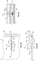
Figure 2B , theelongated body 21 at itsproximal end 23 and a connectingside 27 are connected to acircumferential flange 28 of the mill shell section 5 (which is one half of a split circumferential shell section) and the mill shell sectionouter surface 10. - As best shown in
Figure 1 , thedummy flange 20 is connected to thecircumferential flange 28 so that it is located at or adjacent to a junction between the splitlongitudinal flange 16 and thecircumferential flange 17. Thedummy flange 20 is also arranged so that theelongated body 21 is coincident with thelongitudinal axis 29 of the splitlongitudinal flange 16, preferably by having itslongitudinal axis 29 in alignment or coincident with the longitudinal axis of the splitlongitudinal flange 16. The structure of thedummy flange 20 with its variances in height results in a controlled stiffness that permits the dummy flange to evenly distribute the stress over the joint formed by the split longitudinal and split circumferential flanges, thus effectively removing or reducing the hard spot and redistributing the load (stress) carried by the splitlongitudinal flange 16. - Generally, the variances in height of the
dummy flange 20 over its length from theproximal end 22 to itsdistal end 23 will depend on the stiffness of the adjoining geometry of the split flange, which may be unique for every combination of mill diameter, length, flange dimension and shell section thickness. However, the geometry of the dummy flange is preferably adjusted so that its stiffness reduces most swiftly in the unwelded areas or sections where higher stress can be accepted (generally, the "free", unattached or distal side opposite the connectingside 27, comprising thecurved portion 21b,flat portion 21c and taperedportion 21d) and then blends smoothly where there is welding along its connectingside 27 and itsproximal end 22. This ensures the load (stress) is distributed with efficient use of material. The height and length (and hence profile) can thus be modified or adjusted to accommodate the stiffness of the adjoining geometry of the joint formed by the split longitudinal andcircumferential flanges - Referring to
Figures 3A to 3C , a second embodiment of the invention in the form ofdummy flange 30 is illustrated where corresponding features have been given the same reference numerals. In this embodiment, theelongated body 31 has a gradual decrease in the height from theproximal end 22 to thedistal end 23. There is an initial maximum height 32 at afirst portion 31a, followed by a smooth transition to a base 34 at asecond portion 31b in the form of a curved, tapering portion, as best shown inFigure 3B . Thewidth 25 is also substantially uniform along the length of theelongated body 31 from itsproximal end 22 to itsdistal end 23, as best shown inFigure 3C . - Referring to
Figures 4A to 4C , a third embodiment of the invention in the form ofdummy flange 40 is illustrated where corresponding features have been given the same reference numerals. In this embodiment, theelongated body 41 has a combination of different gradual decreases in the height from theproximal end 22 to thedistal end 23. There is an initialmaximum height 42 at afirst portion 41a, followed by a non-linear decrease at asecond portion 41b in the form of a sinuous portion, then aflat portion 41c and finally a taperedportion 41d, as best shown inFigure 4B . Unlike the previous two embodiments, theelongated body 41 also has a decreasingwidth 45 along its length from itsproximal end 22 to itsdistal end 23, as best shown inFigures 4A and 4C . Theelongated body 41 has an initial maximum width forportions elongated body 41 then narrows in width atportion 41c by way of a curved transition or taper. The same width is then maintained for theportion 41d. - Referring to
Figures 5A to 5C , a fourth embodiment of the invention in the form ofdummy flange 50 is illustrated where corresponding features have been given the same reference numerals. In this embodiment, theelongated body 51 has a gradual decrease in the height from theproximal end 22 to thedistal end 23. There is an initialmaximum height 52 at afirst portion 51a, followed by a linear decrease in the form of a tapered portion, followed by aflat portion 51c and finally another linear decrease in the form of another taperedportion 51d, as best shown inFigure 5B . The width 55 is also substantially uniform along the length of theelongated body 51 from itsproximal end 22 to itsdistal end 23, as best shown inFigure 5C . - The second, third and fourth embodiments work in the same way as the first embodiment described above and so will not be repeated. In other preferred forms, the elongated body has a step-wise decrease in the height of said elongated body from the proximal end to the distal end. This can take the form of a series of descending step portions from the proximal end to the distal end.
- In another preferred form, the elongated body has a variable width from the proximal end to the distal end, similar to the decreases in width from the proximal end to the distal end in the third embodiment illustrated in
Figures 4A to 4C , but with no variation in its height. - Referring to
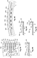
Figures 6A to 6E , a fifth embodiment of the invention is illustrated where corresponding features have been given the same reference numerals. In this fifth embodiment, there is a plurality of dummy flanges 60 connected at their respective proximal ends 22 to thecircumferential flange 28. The dummy flanges are arranged so that there are at least two dummy flanges of the same or equal length, withdummy flanges 60a being the same length,dummy flanges 60b being the same length anddummy flanges 60c being the same length. Each pair of dummy flanges is also of a different length to the other pairs of dummy flanges. In this case,dummy flanges 60a are the longest,dummy flanges 60b are shorter in length anddummy flanges 60c are the shortest. Each pair of dummy flanges also has avariable height 24 butuniform width 25, as best shown inFigures 6B to 6E . - The
dummy flanges 60a have an identical profile to the first embodiment illustrated inFigures 2A to 2C and so its description will not be repeated. The dummy flanges 60b gradually decrease in height, starting with afirst portion 61a at theproximal end 22 that is followed by a sinuous orcurved portion 61b, then aflat portion 61c and finally acurved portion 61d that terminates at thedistal end 23. Thedummy flanges 60c decreases in height more rapidly than theother dummy flanges first portion 61a at theproximal end 22 and then acurved portion 61e that terminates at thedistal end 23. - The
dummy flanges longest dummy flanges 60a are substantially parallel to each other and are close or adjacent to the hard spot, where the split circumferential flange 17 (one half of which is formed by the circumferential flange 28) meets a splitlongitudinal flange 16. Theother dummy flanges dummy flanges 60a. This arrangement of thedummy flanges - A sixth embodiment of the invention is illustrated in
Figures 7A to 7B , where corresponding features have been given the same reference numerals. In this sixth embodiment, the arrangement of thedummy flanges Figures 6A to 6E has been altered by removing onedummy flange 60a so that there aredummy flanges dummy flange 60a. Again, the dummy flanges are arranged substantially parallel to each other and close or adjacent to the hard spot. In this case, thedummy flange 60a would be situated so that it is substantially aligned with the splitlongitudinal flange 16 that would be formed on the other side of thecircumferential flange 28. That is, thedummy flange 60a is coincident with the longitudinal axis of the split longitudinal flange 16 (and hence theother dummy flanges - An example of the second embodiment will now be described with reference to
Figures 8A and8B , where corresponding features have been given the same reference numerals. -
Figure 8A shows the maximum stress range in a typical mill shell joint 70 using FEA techniques. The joint 70 comprises a splitlongitudinal flange 16 that joins a splitcircumferential flange 17, which is composed of twocircumferential flanges 28 of adjoiningmill shell sections 5. Thehard spot 71 occurs at the junction of the splitlongitudinal flange 16 and splitcircumferential flange 17, where there is a stress range of about 85 MPa. Thearea 72 surrounding the hard spot has a stress range of around 65 MPa. - In comparison,
Figure 8B shows the stresses where thedummy flange 20 is connected to the joint 70. Thestress range 75 in the weld radius, where the hard spot would have been is now about 52.5 MPa. Thedummy flange 20 has distributed the stress forces from the hard spot along its length such that there is asmall area 76 where the stress is about 80 MPa, comparable to the hard spot ofFigure 8A , but in an area with no welds. Likewise, in themill shell section 5 there is only a stress range of less than 30 MPa, away from the welded areas and where the allowable stress range is 78MPa. Using the dummy flange thus results in a mill shell design that complies with the 53MPa allowable limit that is derived from British Standard 7608, but is generally accepted as an industry standard. Thus, the use of a dummy flange minimises the risk of hard spots increasing fatigue in the mill shell section, and hence mill shell cracking and failure. Accordingly, mill shell sections can be manufactured with a reduced thickness, reducing mill shell mass, associated manufacturing costs and wastage of material. - In each of the embodiments described above, the elongated body of the dummy flange has a rib-like or fin-like profile. However, other profiles can be used, such as a partly curved or sinuous profile, as best shown in
Figures 9A and 9B . InFigure 9A , thedummy flange 80 has an elongatedbody 80 with a partlycurved section 82, creating a partly curved profile. Similarly, inFigure 9B , thedummy flange 84 has an elongatedbody 85 with asinuous portion 86, creating a partly sinuous profile. In a further preferred form as best shown inFigure 11 , thedummy flange 100 has an elongatedbody 21, similar to the above described embodiments, from which extend additionalelongated bodies 101 of shorter length like branches from a tree trunk. The "branches" 101 can be arranged symmetrically about the "trunk" 21 (as shown by the lowest pair of branches inFigure 11 ) or offset to each other (as shown by the highest pair of branches inFigure 11 ). - In other preferred forms, the invention provides a stress distribution assembly for a joint of a mill shell, comprising a hub and a plurality of stress distribution elements of the first aspect of the present invention, wherein said hub is joined to the respective proximal ends of each said stress distribution element, said hub being connectable to said mill shell joint. In this preferred form, the hub acts as an intermediate connecting element to connect the stress distribution elements to the mill shell joint as well as a central connection for the stress distribution elements. The hub may be substantially linear and extend substantially orthogonal to the stress distribution elements. As best shown in
Figure 10A , thestress distribution assembly 90 has alinear hub 91 to which the respective proximal ends 22 of thedummy flanges Figures 6A to 7B are connected, and thehub 91 is then connected to thecircumferential flange 28. Alternatively, the hub is bulbous or semi-hemispherical, with the stress distribution elements extending divergently or radially outward from the hub, like rays from the sun. As best shown inFigure 10B , thestress distribution assembly 95 has ahemispherical hub 96 to which the respective proximal ends 22 of thedummy flanges 97 are connected, with thehub 96 connected to thecircumferential flange 28. - It will further be appreciated that any of the features in the preferred embodiments of the invention can be combined together and are not necessarily applied in isolation from each other. For example, the stress distribution system illustrated in
Figures 6A to 7B may have dummy flanges of different types together, such as thedummy flange 40 ofFigures 4A to 4C having a reduced width and thedummy flange 95 ofFigure 10B having a partly sinuous profile. - Also, while the preferred embodiment of the invention have been described in relation to longitudinal and circumferential flanges of a mill shell, it will be appreciated that each of the aspects of the invention and the corresponding preferred features are also applicable to flanges, joints and other non-axisymmetric features on other types of constructions and structures, such as industrial kilns.
- As used herein, unless otherwise specified the use of the ordinal adjectives "first", "second", "third", etc., to describe a common object, merely indicate that different instances of like objects are being referred to, and are not intended to imply that the objects so described must be in a given sequence, either temporally, spatially, in ranking, or in any other manner.
- By providing a stress distribution element that reduces or eliminates hard spots that develop in the assembled mill shell, the invention ensures that mill shells can be designed with the optimum mill shell section thickness while still avoiding the risks associated with hard spots developing in the mill shell, thus minimising the risk of mill shell cracking and failure. Furthermore, as the mill shell section thickness can be optimised, the mill shell mass can be significantly reduced. There is also a reduction in manufacturing costs when using thinner mill shell sections and reduced wastage of material. Moreover, the profile of the stress distribution element in terms of its variable dimension (be it height and/or width) can be tailored using FEA techniques to different stresses caused by different characteristics in particular mill shells due to different thicknesses in the flanges (or other non-axisymmetric features), different materials of the mill shell section and other physical parameters. Also, the stress distribution element can be readily retrofitted on existing mill shells. In all these respects, the invention represents a practical and commercially significant improvement over the prior art.
- Although the invention has been described with reference to specific examples, it will be appreciated by those skilled in the art that the invention may be embodied in many other forms, provided they fall into scope of the appended claims.
Claims (7)
- A mill shell comprising:a plurality of mill shell sections connected together, each of said mill shell sections having an arcuate outer surface and at least one flange (11, 12) connected to said outer surface for connecting adjacent mill shell sections together said mill shell section to another mill shell section, characterized in that the mill shell further comprisesone or more stress distribution elements (20) for a joint of the mill shell,the stress distribution element comprising an elongated body (21) having a proximal end (22) for connecting said stress distribution element to said mill shell joint and a distal end (23), wherein said elongated body varies in one dimension from said proximal end to said distal end to widely distribute stress from said proximal end to said distal end, ora stress distribution assembly,wherein said stress distribution assembly comprises a hub (91, 96) and a plurality of said stress distribution elements, said hub connected to the respective proximal ends of each said stress distribution element, said hub being connectable to said mill shell joint, wherein said stress distribution elements extend substantially parallel to each other or substantially divergently from said hub, or a stress distribution system,wherein said stress distribution system comprises a plurality of said stress distribution elements (20), wherein said stress distribution elements are connectable at their respective proximal ends (22) to said mill shell joint, said stress distribution elements extending substantially parallel to each other or substantially divergently from said mill shell joint,wherein two mill shell sections each have respective linear flanges connected together to form a longitudinal flange (11) extending parallel to the longitudinal axis of said mill shell and respective arcuate flanges for connecting said two mill shell sections to a third mill shell section;wherein said third mill shell section comprising an arcuate flange connected to said respective arcuate flanges of said two mill shell sections to form a circumferential flange (12) extending along the circumference of said mill shell,wherein said longitudinal flange and said circumferential flange (11, 12) are connected to each other to form a mill shell joint, andwherein said proximal end (22) of each said stress distribution element or said hub of said stress distribution assembly is connected to said mill shell joint to distribute stress forces from said mill shell joint.
- The mill shell of claim 1, wherein said proximal end of each said stress distribution element (20) or said hub of said stress distribution assembly is connected to said mill shell joint so that the longitudinal axis of said elongated body (21) of said at least one stress distribution element or each said elongated body (21) of said stress distribution assembly is coincident with or parallel to the longitudinal axis of said longitudinal flange (11).
- The mill shell of claim 1 or 2, wherein said elongated body (21) of each said stress distribution element or each said elongated body (21) of said stress distribution assembly is connected to said third mill shell section.
- The mill shell of any one of claims 1 to 3, wherein said proximal end (22) or said hub is connected to said circumferential flange (12).
- The mill shell of claim 4, wherein said proximal end (22) or said hub is connected to said circumferential flange (12) at one side opposite to said longitudinal flange (11).
- The mill shell of any one of claims 1 to 5, wherein said proximal end (22) or said hub is connected to a junction between said longitudinal flange and said circumferential flange (11, 12).
- A method of distributing stress from a joint of a mill shell according to claim 1, said method comprising connecting one or more stress distribution elements (20), the stress distribution assembly or the stress distribution system defined in claim 1 by their respective proximal ends or said hub to said-mill shell joint.
Applications Claiming Priority (2)
| Application Number | Priority Date | Filing Date | Title |
|---|---|---|---|
| AU2013206749A AU2013206749A1 (en) | 2013-07-08 | 2013-07-08 | Stress distribution element for a grinding mill shell |
| PCT/AU2014/000700 WO2015003208A1 (en) | 2013-07-08 | 2014-07-08 | Stress distribution element for a grinding mill shell |
Publications (3)
| Publication Number | Publication Date |
|---|---|
| EP3019277A1 EP3019277A1 (en) | 2016-05-18 |
| EP3019277A4 EP3019277A4 (en) | 2017-03-08 |
| EP3019277B1 true EP3019277B1 (en) | 2022-02-09 |
Family
ID=52279219
Family Applications (1)
| Application Number | Title | Priority Date | Filing Date |
|---|---|---|---|
| EP14823387.7A Active EP3019277B1 (en) | 2013-07-08 | 2014-07-08 | Stress distribution element for a grinding mill shell |
Country Status (11)
| Country | Link |
|---|---|
| US (1) | US10549284B2 (en) |
| EP (1) | EP3019277B1 (en) |
| AU (2) | AU2013206749A1 (en) |
| CA (1) | CA2917059C (en) |
| CL (1) | CL2016000014A1 (en) |
| EA (1) | EA030767B1 (en) |
| ES (1) | ES2912940T3 (en) |
| PE (1) | PE20160130A1 (en) |
| PT (1) | PT3019277T (en) |
| WO (1) | WO2015003208A1 (en) |
| ZA (1) | ZA201600209B (en) |
Families Citing this family (4)
| Publication number | Priority date | Publication date | Assignee | Title |
|---|---|---|---|---|
| AU2013206749A1 (en) * | 2013-07-08 | 2015-01-22 | Outotec (Finland) Oy | Stress distribution element for a grinding mill shell |
| US10967384B2 (en) * | 2018-10-19 | 2021-04-06 | Outotec (Finland) Oy | Grinding mill |
| RU2697080C1 (en) * | 2018-11-10 | 2019-08-12 | Общество с ограниченной ответственностью "СГИ-Инжиниринг" | Drum mill |
| WO2022016211A1 (en) * | 2020-07-20 | 2022-01-27 | Vectis Pty Ltd as trustee for JJB Trust | Grinding mill |
Citations (1)
| Publication number | Priority date | Publication date | Assignee | Title |
|---|---|---|---|---|
| US20020100229A1 (en) * | 2001-01-26 | 2002-08-01 | Siontech Engineering Consultants, Inc. | Seismic-resistant beam-to-column moment connection |
Family Cites Families (29)
| Publication number | Priority date | Publication date | Assignee | Title |
|---|---|---|---|---|
| US3126590A (en) * | 1964-03-31 | Monti | ||
| US924439A (en) * | 1907-11-14 | 1909-06-08 | Charles A Dorn | Crushing and pulverizing mill. |
| US943747A (en) * | 1909-01-13 | 1909-12-21 | John F Hickman | Composite support for posts and poles. |
| US1741744A (en) * | 1924-07-09 | 1929-12-31 | Riley Stoker Corp | Protected grate block for stokers |
| US1843000A (en) * | 1926-07-09 | 1932-01-26 | Riley Stoker Corp | Tuyere block |
| US1807034A (en) * | 1927-02-25 | 1931-05-26 | Hardinge Co Inc | Universal rod mill |
| US2044734A (en) * | 1932-05-23 | 1936-06-16 | Allis Chalmers Mfg Co | Apparatus for stress relieving welded joints |
| US2579238A (en) * | 1948-04-28 | 1951-12-18 | Lippmann Engineering Works | Gyratory crusher |
| GB750584A (en) * | 1953-08-11 | 1956-06-20 | Nordberg Manufacturing Co | Improvements in and relating to gyratory crushers |
| US2860837A (en) * | 1953-08-11 | 1958-11-18 | Nordberg Manufacturing Co | Crusher main frame |
| US3010661A (en) * | 1959-01-28 | 1961-11-28 | Aerofall Mills Inc | Wet material reduction mill |
| US3214829A (en) * | 1962-05-24 | 1965-11-02 | Chicago Rawhide Mfg Co | Seal installation tool with aligning means |
| US3194527A (en) * | 1963-04-01 | 1965-07-13 | Gruss Jack | Bracket |
| JPS51350B2 (en) * | 1971-11-17 | 1976-01-07 | ||
| US3868064A (en) * | 1973-02-23 | 1975-02-25 | Dravo Corp | Apparatus for reducing automobile bodies and other waste to usable scrap |
| US4091594A (en) * | 1976-10-04 | 1978-05-30 | Yujiro Yamashita | Structure for convecting paralled spaced vertical supports |
| DE3149104C2 (en) * | 1981-12-11 | 1985-01-31 | Süddeutsche Kühlerfabrik Julius Fr. Behr GmbH & Co KG, 7000 Stuttgart | Fluid friction clutch |
| US4702425A (en) * | 1986-01-28 | 1987-10-27 | Mcconnell Jr David P | Vibratory crushing apparatus |
| US4825621A (en) * | 1987-12-10 | 1989-05-02 | Mitek Industries, Inc. | Holddown |
| US5083714A (en) * | 1991-04-29 | 1992-01-28 | Cedarapids, Inc. | Vertical shaft impact crusher having a vertically adjustable feed tube |
| US5474239A (en) * | 1994-04-25 | 1995-12-12 | Williams Patent Crusher & Pulverizer Company | Material shredding apparatus |
| US5419278A (en) * | 1994-05-25 | 1995-05-30 | Carter; Daniel C. | Vapor equilibration tray for growing protein crystals |
| US6073405A (en) * | 1995-12-22 | 2000-06-13 | Icf Kaiser Engineers, Inc. | Fitting for effecting bolted connection between a beam and a column in a steel frame structure |
| JP3411888B2 (en) * | 1999-08-26 | 2003-06-03 | 新日本製鐵株式会社 | Joint structure |
| US20080210797A1 (en) * | 2005-04-27 | 2008-09-04 | Alexander Hagedorn | Tubular Mill |
| EP2026393A1 (en) * | 2007-08-13 | 2009-02-18 | Nissan Motor Co., Ltd. | Fuel cell separator and fuel cell |
| US20140166648A1 (en) * | 2011-08-10 | 2014-06-19 | Tokyo Kizai Kogyou Co., Ltd. | Sidewall unit, fabricating method thereof, and fluid storage tank comprising the sidewall unit |
| AU2013206749A1 (en) * | 2013-07-08 | 2015-01-22 | Outotec (Finland) Oy | Stress distribution element for a grinding mill shell |
| FI127273B (en) * | 2014-10-14 | 2018-02-28 | Outotec Finland Oy | Sheath plate, method of making a sheath plate and mill |
-
2013
- 2013-07-08 AU AU2013206749A patent/AU2013206749A1/en not_active Abandoned
-
2014
- 2014-07-08 EP EP14823387.7A patent/EP3019277B1/en active Active
- 2014-07-08 EA EA201592288A patent/EA030767B1/en not_active IP Right Cessation
- 2014-07-08 AU AU2014289961A patent/AU2014289961A1/en not_active Abandoned
- 2014-07-08 CA CA2917059A patent/CA2917059C/en active Active
- 2014-07-08 WO PCT/AU2014/000700 patent/WO2015003208A1/en not_active Ceased
- 2014-07-08 ES ES14823387T patent/ES2912940T3/en active Active
- 2014-07-08 PT PT148233877T patent/PT3019277T/en unknown
- 2014-07-08 PE PE2016000018A patent/PE20160130A1/en active IP Right Grant
- 2014-07-08 US US14/902,349 patent/US10549284B2/en active Active
-
2016
- 2016-01-06 CL CL2016000014A patent/CL2016000014A1/en unknown
- 2016-01-11 ZA ZA2016/00209A patent/ZA201600209B/en unknown
Patent Citations (1)
| Publication number | Priority date | Publication date | Assignee | Title |
|---|---|---|---|---|
| US20020100229A1 (en) * | 2001-01-26 | 2002-08-01 | Siontech Engineering Consultants, Inc. | Seismic-resistant beam-to-column moment connection |
Also Published As
| Publication number | Publication date |
|---|---|
| WO2015003208A1 (en) | 2015-01-15 |
| CA2917059C (en) | 2022-03-15 |
| ES2912940T3 (en) | 2022-05-30 |
| EP3019277A4 (en) | 2017-03-08 |
| US10549284B2 (en) | 2020-02-04 |
| EA201592288A1 (en) | 2016-07-29 |
| EA030767B1 (en) | 2018-09-28 |
| PE20160130A1 (en) | 2016-03-09 |
| ZA201600209B (en) | 2017-04-26 |
| AU2013206749A1 (en) | 2015-01-22 |
| US20160121337A1 (en) | 2016-05-05 |
| AU2014289961A1 (en) | 2016-02-11 |
| CA2917059A1 (en) | 2015-01-15 |
| PT3019277T (en) | 2022-05-16 |
| EP3019277A1 (en) | 2016-05-18 |
| CL2016000014A1 (en) | 2016-10-07 |
Similar Documents
| Publication | Publication Date | Title |
|---|---|---|
| CA2917059C (en) | Stress distribution element for a grinding mill shell | |
| US10731776B2 (en) | Mechanical coupling for mechanical and structural tubing | |
| US20160102724A1 (en) | Concentric Arc Spline Rotational Spring | |
| US7896748B2 (en) | Coupling apparatus | |
| US8591345B2 (en) | Flexible diaphragm coupling for axial force loading | |
| CN102209822A (en) | Reinforcing | |
| JP6171012B2 (en) | Wheel structure for automobile | |
| US11896999B2 (en) | Cast and a shaft assembly for a disc screen | |
| CN103946035B (en) | Wheels for rail vehicles | |
| CN106715932A (en) | Pivot link assembly | |
| CN101255894B (en) | Transmission joint | |
| US11105407B2 (en) | Gear | |
| CN107848009A (en) | Connecting pipe, the steering drag link or track rod and the method for manufacturing the connecting pipe with the connecting pipe | |
| US20140203128A1 (en) | Shell supported grinding mill | |
| US20210283951A1 (en) | Wheel hub and wheel bearing assembly comprising the same | |
| CN102227319B (en) | Rolling bearing device for wheel | |
| EP1631763B1 (en) | Flange joint with at least one flange being mounted in a rotation allowing manner | |
| US10744556B2 (en) | Method for forming a toothed article | |
| KR101812812B1 (en) | Reinforcing element for use with a ventilator hub | |
| KR101536472B1 (en) | Connecting Device for Metal Pipe | |
| KR20180006395A (en) | Modular propulsion unit nozzle | |
| US8939845B2 (en) | Tube yoke for a driveshaft assembly | |
| US20160319617A1 (en) | Casing Exit Mill Assemblies with Replaceable Blade Sleeve | |
| CN102812263A (en) | Process for simultaneously producing more than one bearing ring for a tapered roller bearing | |
| JP2014177940A (en) | Turbine casing inlet assembly construction |
Legal Events
| Date | Code | Title | Description |
|---|---|---|---|
| PUAI | Public reference made under article 153(3) epc to a published international application that has entered the european phase |
Free format text: ORIGINAL CODE: 0009012 |
|
| 17P | Request for examination filed |
Effective date: 20160205 |
|
| AK | Designated contracting states |
Kind code of ref document: A1 Designated state(s): AL AT BE BG CH CY CZ DE DK EE ES FI FR GB GR HR HU IE IS IT LI LT LU LV MC MK MT NL NO PL PT RO RS SE SI SK SM TR |
|
| AX | Request for extension of the european patent |
Extension state: BA ME |
|
| DAX | Request for extension of the european patent (deleted) | ||
| REG | Reference to a national code |
Ref country code: DE Ref legal event code: R079 Ref document number: 602014082453 Country of ref document: DE Free format text: PREVIOUS MAIN CLASS: B02C0023000000 Ipc: B02C0017180000 |
|
| A4 | Supplementary search report drawn up and despatched |
Effective date: 20170206 |
|
| RIC1 | Information provided on ipc code assigned before grant |
Ipc: B02C 17/04 20060101ALI20170127BHEP Ipc: F16B 5/02 20060101ALI20170127BHEP Ipc: B02C 17/18 20060101AFI20170127BHEP |
|
| STAA | Information on the status of an ep patent application or granted ep patent |
Free format text: STATUS: EXAMINATION IS IN PROGRESS |
|
| 17Q | First examination report despatched |
Effective date: 20180612 |
|
| GRAP | Despatch of communication of intention to grant a patent |
Free format text: ORIGINAL CODE: EPIDOSNIGR1 |
|
| STAA | Information on the status of an ep patent application or granted ep patent |
Free format text: STATUS: GRANT OF PATENT IS INTENDED |
|
| INTG | Intention to grant announced |
Effective date: 20210908 |
|
| GRAS | Grant fee paid |
Free format text: ORIGINAL CODE: EPIDOSNIGR3 |
|
| GRAA | (expected) grant |
Free format text: ORIGINAL CODE: 0009210 |
|
| STAA | Information on the status of an ep patent application or granted ep patent |
Free format text: STATUS: THE PATENT HAS BEEN GRANTED |
|
| AK | Designated contracting states |
Kind code of ref document: B1 Designated state(s): AL AT BE BG CH CY CZ DE DK EE ES FI FR GB GR HR HU IE IS IT LI LT LU LV MC MK MT NL NO PL PT RO RS SE SI SK SM TR |
|
| RAP1 | Party data changed (applicant data changed or rights of an application transferred) |
Owner name: METSO OUTOTEC FINLAND OY |
|
| REG | Reference to a national code |
Ref country code: GB Ref legal event code: FG4D |
|
| REG | Reference to a national code |
Ref country code: CH Ref legal event code: EP Ref country code: AT Ref legal event code: REF Ref document number: 1467172 Country of ref document: AT Kind code of ref document: T Effective date: 20220215 |
|
| REG | Reference to a national code |
Ref country code: IE Ref legal event code: FG4D |
|
| REG | Reference to a national code |
Ref country code: DE Ref legal event code: R096 Ref document number: 602014082453 Country of ref document: DE |
|
| REG | Reference to a national code |
Ref country code: FI Ref legal event code: FGE |
|
| REG | Reference to a national code |
Ref country code: PT Ref legal event code: SC4A Ref document number: 3019277 Country of ref document: PT Date of ref document: 20220516 Kind code of ref document: T Free format text: AVAILABILITY OF NATIONAL TRANSLATION Effective date: 20220506 |
|
| REG | Reference to a national code |
Ref country code: ES Ref legal event code: FG2A Ref document number: 2912940 Country of ref document: ES Kind code of ref document: T3 Effective date: 20220530 |
|
| REG | Reference to a national code |
Ref country code: SE Ref legal event code: TRGR |
|
| REG | Reference to a national code |
Ref country code: LT Ref legal event code: MG9D |
|
| REG | Reference to a national code |
Ref country code: NL Ref legal event code: MP Effective date: 20220209 |
|
| REG | Reference to a national code |
Ref country code: AT Ref legal event code: MK05 Ref document number: 1467172 Country of ref document: AT Kind code of ref document: T Effective date: 20220209 |
|
| PG25 | Lapsed in a contracting state [announced via postgrant information from national office to epo] |
Ref country code: RS Free format text: LAPSE BECAUSE OF FAILURE TO SUBMIT A TRANSLATION OF THE DESCRIPTION OR TO PAY THE FEE WITHIN THE PRESCRIBED TIME-LIMIT Effective date: 20220209 Ref country code: NO Free format text: LAPSE BECAUSE OF FAILURE TO SUBMIT A TRANSLATION OF THE DESCRIPTION OR TO PAY THE FEE WITHIN THE PRESCRIBED TIME-LIMIT Effective date: 20220509 Ref country code: NL Free format text: LAPSE BECAUSE OF FAILURE TO SUBMIT A TRANSLATION OF THE DESCRIPTION OR TO PAY THE FEE WITHIN THE PRESCRIBED TIME-LIMIT Effective date: 20220209 Ref country code: LT Free format text: LAPSE BECAUSE OF FAILURE TO SUBMIT A TRANSLATION OF THE DESCRIPTION OR TO PAY THE FEE WITHIN THE PRESCRIBED TIME-LIMIT Effective date: 20220209 Ref country code: HR Free format text: LAPSE BECAUSE OF FAILURE TO SUBMIT A TRANSLATION OF THE DESCRIPTION OR TO PAY THE FEE WITHIN THE PRESCRIBED TIME-LIMIT Effective date: 20220209 Ref country code: BG Free format text: LAPSE BECAUSE OF FAILURE TO SUBMIT A TRANSLATION OF THE DESCRIPTION OR TO PAY THE FEE WITHIN THE PRESCRIBED TIME-LIMIT Effective date: 20220509 |
|
| PG25 | Lapsed in a contracting state [announced via postgrant information from national office to epo] |
Ref country code: PL Free format text: LAPSE BECAUSE OF FAILURE TO SUBMIT A TRANSLATION OF THE DESCRIPTION OR TO PAY THE FEE WITHIN THE PRESCRIBED TIME-LIMIT Effective date: 20220209 Ref country code: LV Free format text: LAPSE BECAUSE OF FAILURE TO SUBMIT A TRANSLATION OF THE DESCRIPTION OR TO PAY THE FEE WITHIN THE PRESCRIBED TIME-LIMIT Effective date: 20220209 Ref country code: GR Free format text: LAPSE BECAUSE OF FAILURE TO SUBMIT A TRANSLATION OF THE DESCRIPTION OR TO PAY THE FEE WITHIN THE PRESCRIBED TIME-LIMIT Effective date: 20220510 Ref country code: AT Free format text: LAPSE BECAUSE OF FAILURE TO SUBMIT A TRANSLATION OF THE DESCRIPTION OR TO PAY THE FEE WITHIN THE PRESCRIBED TIME-LIMIT Effective date: 20220209 |
|
| PG25 | Lapsed in a contracting state [announced via postgrant information from national office to epo] |
Ref country code: IS Free format text: LAPSE BECAUSE OF FAILURE TO SUBMIT A TRANSLATION OF THE DESCRIPTION OR TO PAY THE FEE WITHIN THE PRESCRIBED TIME-LIMIT Effective date: 20220609 |
|
| PG25 | Lapsed in a contracting state [announced via postgrant information from national office to epo] |
Ref country code: SM Free format text: LAPSE BECAUSE OF FAILURE TO SUBMIT A TRANSLATION OF THE DESCRIPTION OR TO PAY THE FEE WITHIN THE PRESCRIBED TIME-LIMIT Effective date: 20220209 Ref country code: SK Free format text: LAPSE BECAUSE OF FAILURE TO SUBMIT A TRANSLATION OF THE DESCRIPTION OR TO PAY THE FEE WITHIN THE PRESCRIBED TIME-LIMIT Effective date: 20220209 Ref country code: RO Free format text: LAPSE BECAUSE OF FAILURE TO SUBMIT A TRANSLATION OF THE DESCRIPTION OR TO PAY THE FEE WITHIN THE PRESCRIBED TIME-LIMIT Effective date: 20220209 Ref country code: EE Free format text: LAPSE BECAUSE OF FAILURE TO SUBMIT A TRANSLATION OF THE DESCRIPTION OR TO PAY THE FEE WITHIN THE PRESCRIBED TIME-LIMIT Effective date: 20220209 Ref country code: DK Free format text: LAPSE BECAUSE OF FAILURE TO SUBMIT A TRANSLATION OF THE DESCRIPTION OR TO PAY THE FEE WITHIN THE PRESCRIBED TIME-LIMIT Effective date: 20220209 Ref country code: CZ Free format text: LAPSE BECAUSE OF FAILURE TO SUBMIT A TRANSLATION OF THE DESCRIPTION OR TO PAY THE FEE WITHIN THE PRESCRIBED TIME-LIMIT Effective date: 20220209 |
|
| REG | Reference to a national code |
Ref country code: DE Ref legal event code: R097 Ref document number: 602014082453 Country of ref document: DE |
|
| PG25 | Lapsed in a contracting state [announced via postgrant information from national office to epo] |
Ref country code: AL Free format text: LAPSE BECAUSE OF FAILURE TO SUBMIT A TRANSLATION OF THE DESCRIPTION OR TO PAY THE FEE WITHIN THE PRESCRIBED TIME-LIMIT Effective date: 20220209 |
|
| PLBE | No opposition filed within time limit |
Free format text: ORIGINAL CODE: 0009261 |
|
| STAA | Information on the status of an ep patent application or granted ep patent |
Free format text: STATUS: NO OPPOSITION FILED WITHIN TIME LIMIT |
|
| 26N | No opposition filed |
Effective date: 20221110 |
|
| REG | Reference to a national code |
Ref country code: DE Ref legal event code: R119 Ref document number: 602014082453 Country of ref document: DE |
|
| PG25 | Lapsed in a contracting state [announced via postgrant information from national office to epo] |
Ref country code: SI Free format text: LAPSE BECAUSE OF FAILURE TO SUBMIT A TRANSLATION OF THE DESCRIPTION OR TO PAY THE FEE WITHIN THE PRESCRIBED TIME-LIMIT Effective date: 20220209 Ref country code: MC Free format text: LAPSE BECAUSE OF FAILURE TO SUBMIT A TRANSLATION OF THE DESCRIPTION OR TO PAY THE FEE WITHIN THE PRESCRIBED TIME-LIMIT Effective date: 20220209 |
|
| REG | Reference to a national code |
Ref country code: CH Ref legal event code: PL |
|
| GBPC | Gb: european patent ceased through non-payment of renewal fee |
Effective date: 20220708 |
|
| REG | Reference to a national code |
Ref country code: BE Ref legal event code: MM Effective date: 20220731 |
|
| PG25 | Lapsed in a contracting state [announced via postgrant information from national office to epo] |
Ref country code: LU Free format text: LAPSE BECAUSE OF NON-PAYMENT OF DUE FEES Effective date: 20220708 Ref country code: LI Free format text: LAPSE BECAUSE OF NON-PAYMENT OF DUE FEES Effective date: 20220731 Ref country code: FR Free format text: LAPSE BECAUSE OF NON-PAYMENT OF DUE FEES Effective date: 20220731 Ref country code: CH Free format text: LAPSE BECAUSE OF NON-PAYMENT OF DUE FEES Effective date: 20220731 |
|
| PG25 | Lapsed in a contracting state [announced via postgrant information from national office to epo] |
Ref country code: GB Free format text: LAPSE BECAUSE OF NON-PAYMENT OF DUE FEES Effective date: 20220708 Ref country code: DE Free format text: LAPSE BECAUSE OF NON-PAYMENT OF DUE FEES Effective date: 20230201 Ref country code: BE Free format text: LAPSE BECAUSE OF NON-PAYMENT OF DUE FEES Effective date: 20220731 |
|
| PG25 | Lapsed in a contracting state [announced via postgrant information from national office to epo] |
Ref country code: IT Free format text: LAPSE BECAUSE OF FAILURE TO SUBMIT A TRANSLATION OF THE DESCRIPTION OR TO PAY THE FEE WITHIN THE PRESCRIBED TIME-LIMIT Effective date: 20220209 Ref country code: IE Free format text: LAPSE BECAUSE OF NON-PAYMENT OF DUE FEES Effective date: 20220708 |
|
| P01 | Opt-out of the competence of the unified patent court (upc) registered |
Effective date: 20230627 |
|
| PG25 | Lapsed in a contracting state [announced via postgrant information from national office to epo] |
Ref country code: HU Free format text: LAPSE BECAUSE OF FAILURE TO SUBMIT A TRANSLATION OF THE DESCRIPTION OR TO PAY THE FEE WITHIN THE PRESCRIBED TIME-LIMIT; INVALID AB INITIO Effective date: 20140708 |
|
| PG25 | Lapsed in a contracting state [announced via postgrant information from national office to epo] |
Ref country code: MK Free format text: LAPSE BECAUSE OF FAILURE TO SUBMIT A TRANSLATION OF THE DESCRIPTION OR TO PAY THE FEE WITHIN THE PRESCRIBED TIME-LIMIT Effective date: 20220209 Ref country code: CY Free format text: LAPSE BECAUSE OF FAILURE TO SUBMIT A TRANSLATION OF THE DESCRIPTION OR TO PAY THE FEE WITHIN THE PRESCRIBED TIME-LIMIT Effective date: 20220209 |
|
| PG25 | Lapsed in a contracting state [announced via postgrant information from national office to epo] |
Ref country code: MT Free format text: LAPSE BECAUSE OF FAILURE TO SUBMIT A TRANSLATION OF THE DESCRIPTION OR TO PAY THE FEE WITHIN THE PRESCRIBED TIME-LIMIT Effective date: 20220209 |
|
| PGFP | Annual fee paid to national office [announced via postgrant information from national office to epo] |
Ref country code: PT Payment date: 20250623 Year of fee payment: 12 |
|
| PGFP | Annual fee paid to national office [announced via postgrant information from national office to epo] |
Ref country code: SE Payment date: 20250610 Year of fee payment: 12 |
|
| PGFP | Annual fee paid to national office [announced via postgrant information from national office to epo] |
Ref country code: FI Payment date: 20250715 Year of fee payment: 12 Ref country code: ES Payment date: 20250806 Year of fee payment: 12 |
|
| PGFP | Annual fee paid to national office [announced via postgrant information from national office to epo] |
Ref country code: TR Payment date: 20250702 Year of fee payment: 12 |
|
| REG | Reference to a national code |
Ref country code: ES Ref legal event code: PC2A Owner name: METSO FINLAND OY Effective date: 20260331 |