EP3019075B1 - Determination of a hemodynamic parameter - Google Patents
Determination of a hemodynamic parameter Download PDFInfo
- Publication number
- EP3019075B1 EP3019075B1 EP14822728.3A EP14822728A EP3019075B1 EP 3019075 B1 EP3019075 B1 EP 3019075B1 EP 14822728 A EP14822728 A EP 14822728A EP 3019075 B1 EP3019075 B1 EP 3019075B1
- Authority
- EP
- European Patent Office
- Prior art keywords
- standard deviation
- data
- hemodynamic parameter
- determining
- computer
- Prior art date
- Legal status (The legal status is an assumption and is not a legal conclusion. Google has not performed a legal analysis and makes no representation as to the accuracy of the status listed.)
- Active
Links
- 230000000004 hemodynamic effect Effects 0.000 title claims description 62
- 238000000034 method Methods 0.000 claims description 104
- 230000006870 function Effects 0.000 claims description 35
- 230000036772 blood pressure Effects 0.000 claims description 24
- 230000035485 pulse pressure Effects 0.000 claims description 11
- 230000035488 systolic blood pressure Effects 0.000 claims description 11
- 230000008569 process Effects 0.000 description 30
- 238000012545 processing Methods 0.000 description 13
- 230000004872 arterial blood pressure Effects 0.000 description 12
- 238000004364 calculation method Methods 0.000 description 12
- SONNWYBIRXJNDC-VIFPVBQESA-N phenylephrine Chemical compound CNC[C@H](O)C1=CC=CC(O)=C1 SONNWYBIRXJNDC-VIFPVBQESA-N 0.000 description 11
- 229960001802 phenylephrine Drugs 0.000 description 11
- 230000000747 cardiac effect Effects 0.000 description 8
- 238000004590 computer program Methods 0.000 description 8
- 230000029058 respiratory gaseous exchange Effects 0.000 description 7
- 238000010586 diagram Methods 0.000 description 6
- 239000012530 fluid Substances 0.000 description 6
- 230000004043 responsiveness Effects 0.000 description 6
- 230000000694 effects Effects 0.000 description 5
- 238000001914 filtration Methods 0.000 description 5
- 210000002321 radial artery Anatomy 0.000 description 5
- 229940124572 antihypotensive agent Drugs 0.000 description 4
- 238000004422 calculation algorithm Methods 0.000 description 4
- 238000012544 monitoring process Methods 0.000 description 4
- 239000005526 vasoconstrictor agent Substances 0.000 description 4
- 101000802640 Homo sapiens Lactosylceramide 4-alpha-galactosyltransferase Proteins 0.000 description 3
- 102100035838 Lactosylceramide 4-alpha-galactosyltransferase Human genes 0.000 description 3
- 210000000709 aorta Anatomy 0.000 description 3
- 210000001367 artery Anatomy 0.000 description 3
- 230000002526 effect on cardiovascular system Effects 0.000 description 3
- 230000002792 vascular Effects 0.000 description 3
- 241001465754 Metazoa Species 0.000 description 2
- 230000008901 benefit Effects 0.000 description 2
- 239000008280 blood Substances 0.000 description 2
- 210000004369 blood Anatomy 0.000 description 2
- 238000009530 blood pressure measurement Methods 0.000 description 2
- 238000005516 engineering process Methods 0.000 description 2
- 230000006872 improvement Effects 0.000 description 2
- 239000000463 material Substances 0.000 description 2
- 238000005259 measurement Methods 0.000 description 2
- 238000005399 mechanical ventilation Methods 0.000 description 2
- 230000007246 mechanism Effects 0.000 description 2
- 230000003287 optical effect Effects 0.000 description 2
- 230000036581 peripheral resistance Effects 0.000 description 2
- 210000001147 pulmonary artery Anatomy 0.000 description 2
- 230000035945 sensitivity Effects 0.000 description 2
- 238000003860 storage Methods 0.000 description 2
- 238000012360 testing method Methods 0.000 description 2
- 230000003321 amplification Effects 0.000 description 1
- 238000004458 analytical method Methods 0.000 description 1
- 230000017531 blood circulation Effects 0.000 description 1
- 210000002302 brachial artery Anatomy 0.000 description 1
- 230000008859 change Effects 0.000 description 1
- 230000001143 conditioned effect Effects 0.000 description 1
- 230000003750 conditioning effect Effects 0.000 description 1
- 238000003745 diagnosis Methods 0.000 description 1
- 201000010099 disease Diseases 0.000 description 1
- 208000037265 diseases, disorders, signs and symptoms Diseases 0.000 description 1
- 238000002474 experimental method Methods 0.000 description 1
- 210000001105 femoral artery Anatomy 0.000 description 1
- 208000014674 injury Diseases 0.000 description 1
- 230000009545 invasion Effects 0.000 description 1
- 238000004519 manufacturing process Methods 0.000 description 1
- 238000003199 nucleic acid amplification method Methods 0.000 description 1
- 238000005457 optimization Methods 0.000 description 1
- 238000006213 oxygenation reaction Methods 0.000 description 1
- 230000002093 peripheral effect Effects 0.000 description 1
- 230000036316 preload Effects 0.000 description 1
- 238000002106 pulse oximetry Methods 0.000 description 1
- 230000000241 respiratory effect Effects 0.000 description 1
- 210000005245 right atrium Anatomy 0.000 description 1
- 239000000523 sample Substances 0.000 description 1
- 238000005070 sampling Methods 0.000 description 1
- 239000004065 semiconductor Substances 0.000 description 1
- 230000008733 trauma Effects 0.000 description 1
- 238000002604 ultrasonography Methods 0.000 description 1
- 238000011144 upstream manufacturing Methods 0.000 description 1
- 210000000707 wrist Anatomy 0.000 description 1
Images


Classifications
-
- A—HUMAN NECESSITIES
- A61—MEDICAL OR VETERINARY SCIENCE; HYGIENE
- A61B—DIAGNOSIS; SURGERY; IDENTIFICATION
- A61B5/00—Measuring for diagnostic purposes; Identification of persons
- A61B5/72—Signal processing specially adapted for physiological signals or for diagnostic purposes
- A61B5/7271—Specific aspects of physiological measurement analysis
- A61B5/7278—Artificial waveform generation or derivation, e.g. synthesising signals from measured signals
-
- A—HUMAN NECESSITIES
- A61—MEDICAL OR VETERINARY SCIENCE; HYGIENE
- A61B—DIAGNOSIS; SURGERY; IDENTIFICATION
- A61B5/00—Measuring for diagnostic purposes; Identification of persons
- A61B5/02—Detecting, measuring or recording pulse, heart rate, blood pressure or blood flow; Combined pulse/heart-rate/blood pressure determination; Evaluating a cardiovascular condition not otherwise provided for, e.g. using combinations of techniques provided for in this group with electrocardiography or electroauscultation; Heart catheters for measuring blood pressure
- A61B5/0205—Simultaneously evaluating both cardiovascular conditions and different types of body conditions, e.g. heart and respiratory condition
-
- A—HUMAN NECESSITIES
- A61—MEDICAL OR VETERINARY SCIENCE; HYGIENE
- A61B—DIAGNOSIS; SURGERY; IDENTIFICATION
- A61B5/00—Measuring for diagnostic purposes; Identification of persons
- A61B5/02—Detecting, measuring or recording pulse, heart rate, blood pressure or blood flow; Combined pulse/heart-rate/blood pressure determination; Evaluating a cardiovascular condition not otherwise provided for, e.g. using combinations of techniques provided for in this group with electrocardiography or electroauscultation; Heart catheters for measuring blood pressure
- A61B5/021—Measuring pressure in heart or blood vessels
- A61B5/02108—Measuring pressure in heart or blood vessels from analysis of pulse wave characteristics
-
- A—HUMAN NECESSITIES
- A61—MEDICAL OR VETERINARY SCIENCE; HYGIENE
- A61B—DIAGNOSIS; SURGERY; IDENTIFICATION
- A61B5/00—Measuring for diagnostic purposes; Identification of persons
- A61B5/02—Detecting, measuring or recording pulse, heart rate, blood pressure or blood flow; Combined pulse/heart-rate/blood pressure determination; Evaluating a cardiovascular condition not otherwise provided for, e.g. using combinations of techniques provided for in this group with electrocardiography or electroauscultation; Heart catheters for measuring blood pressure
- A61B5/021—Measuring pressure in heart or blood vessels
- A61B5/0215—Measuring pressure in heart or blood vessels by means inserted into the body
-
- A—HUMAN NECESSITIES
- A61—MEDICAL OR VETERINARY SCIENCE; HYGIENE
- A61B—DIAGNOSIS; SURGERY; IDENTIFICATION
- A61B5/00—Measuring for diagnostic purposes; Identification of persons
- A61B5/02—Detecting, measuring or recording pulse, heart rate, blood pressure or blood flow; Combined pulse/heart-rate/blood pressure determination; Evaluating a cardiovascular condition not otherwise provided for, e.g. using combinations of techniques provided for in this group with electrocardiography or electroauscultation; Heart catheters for measuring blood pressure
- A61B5/024—Detecting, measuring or recording pulse rate or heart rate
- A61B5/02416—Detecting, measuring or recording pulse rate or heart rate using photoplethysmograph signals, e.g. generated by infrared radiation
-
- A—HUMAN NECESSITIES
- A61—MEDICAL OR VETERINARY SCIENCE; HYGIENE
- A61B—DIAGNOSIS; SURGERY; IDENTIFICATION
- A61B5/00—Measuring for diagnostic purposes; Identification of persons
- A61B5/02—Detecting, measuring or recording pulse, heart rate, blood pressure or blood flow; Combined pulse/heart-rate/blood pressure determination; Evaluating a cardiovascular condition not otherwise provided for, e.g. using combinations of techniques provided for in this group with electrocardiography or electroauscultation; Heart catheters for measuring blood pressure
- A61B5/026—Measuring blood flow
- A61B5/0261—Measuring blood flow using optical means, e.g. infrared light
-
- A—HUMAN NECESSITIES
- A61—MEDICAL OR VETERINARY SCIENCE; HYGIENE
- A61B—DIAGNOSIS; SURGERY; IDENTIFICATION
- A61B5/00—Measuring for diagnostic purposes; Identification of persons
- A61B5/02—Detecting, measuring or recording pulse, heart rate, blood pressure or blood flow; Combined pulse/heart-rate/blood pressure determination; Evaluating a cardiovascular condition not otherwise provided for, e.g. using combinations of techniques provided for in this group with electrocardiography or electroauscultation; Heart catheters for measuring blood pressure
- A61B5/026—Measuring blood flow
- A61B5/029—Measuring or recording blood output from the heart, e.g. minute volume
-
- A—HUMAN NECESSITIES
- A61—MEDICAL OR VETERINARY SCIENCE; HYGIENE
- A61B—DIAGNOSIS; SURGERY; IDENTIFICATION
- A61B5/00—Measuring for diagnostic purposes; Identification of persons
- A61B5/02—Detecting, measuring or recording pulse, heart rate, blood pressure or blood flow; Combined pulse/heart-rate/blood pressure determination; Evaluating a cardiovascular condition not otherwise provided for, e.g. using combinations of techniques provided for in this group with electrocardiography or electroauscultation; Heart catheters for measuring blood pressure
- A61B5/026—Measuring blood flow
- A61B5/0295—Measuring blood flow using plethysmography, i.e. measuring the variations in the volume of a body part as modified by the circulation of blood therethrough, e.g. impedance plethysmography
-
- A—HUMAN NECESSITIES
- A61—MEDICAL OR VETERINARY SCIENCE; HYGIENE
- A61B—DIAGNOSIS; SURGERY; IDENTIFICATION
- A61B5/00—Measuring for diagnostic purposes; Identification of persons
- A61B5/72—Signal processing specially adapted for physiological signals or for diagnostic purposes
- A61B5/7203—Signal processing specially adapted for physiological signals or for diagnostic purposes for noise prevention, reduction or removal
- A61B5/7217—Signal processing specially adapted for physiological signals or for diagnostic purposes for noise prevention, reduction or removal of noise originating from a therapeutic or surgical apparatus, e.g. from a pacemaker
-
- A—HUMAN NECESSITIES
- A61—MEDICAL OR VETERINARY SCIENCE; HYGIENE
- A61B—DIAGNOSIS; SURGERY; IDENTIFICATION
- A61B5/00—Measuring for diagnostic purposes; Identification of persons
- A61B5/72—Signal processing specially adapted for physiological signals or for diagnostic purposes
- A61B5/7271—Specific aspects of physiological measurement analysis
- A61B5/7275—Determining trends in physiological measurement data; Predicting development of a medical condition based on physiological measurements, e.g. determining a risk factor
-
- G—PHYSICS
- G16—INFORMATION AND COMMUNICATION TECHNOLOGY [ICT] SPECIALLY ADAPTED FOR SPECIFIC APPLICATION FIELDS
- G16H—HEALTHCARE INFORMATICS, i.e. INFORMATION AND COMMUNICATION TECHNOLOGY [ICT] SPECIALLY ADAPTED FOR THE HANDLING OR PROCESSING OF MEDICAL OR HEALTHCARE DATA
- G16H50/00—ICT specially adapted for medical diagnosis, medical simulation or medical data mining; ICT specially adapted for detecting, monitoring or modelling epidemics or pandemics
- G16H50/20—ICT specially adapted for medical diagnosis, medical simulation or medical data mining; ICT specially adapted for detecting, monitoring or modelling epidemics or pandemics for computer-aided diagnosis, e.g. based on medical expert systems
Definitions
- This disclosure is related to the field of patient hemodynamic monitoring and digital signal processing. This disclosure specifically relates to a method of calculating real-time hemodynamic parameters.
- Indicators such as stroke volume (SV), cardiac output (CO), end-diastolic volume, ejection fraction, stroke volume variation (SVV), pulse pressure variation (PPV), systolic pressure variations (SPV), and plethysmographic variability index (PVI), among others, are important not only for diagnosis of disease, but also for "real-time" monitoring of preload dependence, fluid responsiveness, or volume responsiveness condition of both human and animal subjects. Few hospitals are therefore without some form of equipment to monitor one or more of these cardiac parameters. Many techniques, including invasive techniques, non-invasive techniques, and combinations thereof, are in use and even more have been proposed in the literature. References that disclose determination of hemodynamic parameters include WO2011094487 (Jian et al., filed 28 Jan., 2011 ) and WO 2009023713 (Derderian et al., filed 13 Aug., 2008 ).
- One way to obtain a hemodynamic parameter is to mount a flow-measuring device on a catheter, and position the device in or near the subject's heart.
- Some such devices inject either a bolus of material or energy (usually heat) at an upstream position, such as in the right atrium, and determine flow based on the characteristics of the injected material or energy at a downstream position, such as in the pulmonary artery.
- Patents that disclose implementations of such invasive techniques include: U.S. Pat. No. 4,236,527 (Newbower et al., 2 Dec. 1980 ); U.S. Pat. No. 4,507,974 (Yelderman, 2 Apr. 1985 ); U.S. Pat. No.
- PCM pulse contour method
- the three required parameters of the model are usually determined either empirically, through a complex calibration process, or from compiled "anthropometric" data, i.e., data about the age, sex, height, weight, and/or other parameters of other patients or test subjects.
- PCM-based systems can monitor hemodynamic parameters using blood pressure measurements taken using a variety of measurement apparatus, such as a finger cuff, and can do so more or less continuously.
- Many improvements, with varying degrees of complexity, have been proposed for improving the accuracy of the basic PCM model.
- the present disclosure offers an improvement over the PCM model or any other models discussed in this section.
- WO2005/055825 A1 discloses one or more cardiovascular parameters which are estimated as a function of the arterial pressure waveform, in particular, using at least one statistical moment of a discrete representation pressure waveform having an order greater than one.
- Arterial pressure may be measured invasively or non-invasively.
- Arterial compliance, an exponential pressure decay constant, vascular resistance, cardiac output, and stroke volume are examples of cardiovascular parameters that can be estimated using various aspects of the invention.
- cardiac stroke volume of a subject is estimated as a function of a value derived from the pressure waveform.
- two or more of the first four moments - mean, standard deviation, skewness, and kurtosis - of the pressure waveform are used to estimate the cardiovascular parameter(s) of interest, as well as heart rate, statistical moments of a set of pressure-weighted time values, and certain anthropometric patient measurements such as age, sex, body surface area, etc.
- US 2005/187481 A1 discloses a method and system for determining the stroke volume variation from a blood pressure data trace.
- the present invention is defined by the appended claims and relates to a method and an apparatus for determining a hemodynamic parameter, according to independent claims 1 and 10, respectively.
- the hemodynamic parameter may comprise a stroke volume variation (SVV), and the data comprises blood pressure data.
- SVV stroke volume variation
- the hemodynamic parameter may comprise a pulse pressure variation (PPV), and the data comprises pulse pressure data.
- PV pulse pressure variation
- the hemodynamic parameter may comprise a systolic pressure variation (SPV), and the data comprises systolic pressure data.
- SPV systolic pressure variation
- the hemodynamic parameter may comprise a plethysmographic variability index (PVI), and the data comprises pulse oximeter waveform data.
- PVI plethysmographic variability index
- the method comprises determining, using a computing device processor, a polynomial function that fits the first standard deviation, the polynomial function being associated with at least one polynomial coefficient.
- the polynomial function may be based on a least-squares function.
- Receiving data may comprise measuring at least one arterial blood pressure waveform and identifying the at least one heart beat.
- the method further comprises subtracting the polynomial function from the first standard deviation.
- Determining the hemodynamic parameter may further comprise determining the hemodynamic parameter based on a constant, a standard deviation of the second standard deviation, and a mean of the first standard deviation.
- Determining the hemodynamic parameter may further comprise determining the hemodynamic parameter based on multiplying the constant and the standard deviation of the second standard deviation to produce a first computation, and dividing the first computation by the mean of the first standard deviation.
- the polynomial function may be a first order polynomial function.
- the polynomial function may be an n th order polynomial function.
- An exemplary computer program product for determining a hemodynamic parameter comprises a non-transitory computer-readable medium comprising a set of codes for causing a computer to: receive data associated with at least one heart beat; calculate a first standard deviation for at least a portion of the data; interpolate a second standard deviation for at least a second portion of the data; and determine the hemodynamic parameter based on the first standard deviation and the second standard deviation.
- Another exemplary apparatus for determining a hemodynamic parameter comprises means for receiving data associated with at least one heart beat; means for calculating a first standard deviation for at least a portion of the data; means for interpolating a second standard deviation for at least a second portion of the data; and means for determining the hemodynamic parameter based on the first standard deviation and the second standard deviation.
- Another method for determining a hemodynamic parameter comprises: receiving data associated with at least one heart beat; calculating a first standard deviation for at least a portion of the data; using a Fourier transform and filtering scheme to remove at least a second portion of the data; using an inverse Fourier transform to obtain a second standard deviation for at least a second portion of the data; and determining, using a computing device processor, the hemodynamic parameter based on the first standard deviation and the second standard deviation.
- Apparatus and computer program product may also be provided based on this method.
- Yet another method for determining a hemodynamic parameter comprises: receiving a first portion of data associated with at least one heart beat; interpolating a second portion of the data based on the first portion of the data; calculating at least one standard deviation for at least one of the first portion of the data or the second portion of the data; and determining, using a computing device processor, the hemodynamic parameter based on the at least one standard deviation.
- the hemodynamic parameter comprises at least one of SVV, PPV, SPV, or PVI. Apparatus and computer program product may also be provided based on this method.
- the disclosure is directed to apparatuses, methods and computer program products for determining or calculating a hemodynamic parameter.
- This disclosure provides a new method to calculate hemodynamic parameters such as stroke volume variation (SVV), pulse pressure variation (PPV), systolic pressure variation (SPV), and plethysmographic variability index (PVI) based on blood pressure waveforms.
- hemodynamic parameters such as stroke volume variation (SVV), pulse pressure variation (PPV), systolic pressure variation (SPV), and plethysmographic variability index (PVI) based on blood pressure waveforms.
- SVV stroke volume variation
- PV pulse pressure variation
- SPV systolic pressure variation
- PVI plethysmographic variability index
- Exemplary methods of the present disclosure are directed to determining SVV. However, these methods or variations of these methods may be used to determine other hemodynamic parameters, including, but not limited to, SPV, PPV, or PVI.
- a method for calculating SVV which is induced by mechanical ventilation, predicts fluid responsiveness with high sensitivity and specificity. As a result, it is often used by clinicians as a guide for fluid optimization.
- This method of calculation or determination of the SVV may be referred to as the first method.
- the first method does reasonably well in predicting fluid responsiveness. The issue of this method, however, is that it does not completely distinguish the variation of stroke volume due to the mechanical ventilation from variation due to other causes. As a result, the first method may not predict fluid responsiveness with high accuracy (e.g., accuracy equal to or greater than a threshold accuracy).
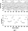
- Figure 1 shows an example of radial artery pressure before a bolus vasopressor of phenylephrine is given to patients.
- the top plot shows the pressure and the bottom plot shows the standard deviation of blood pressure in each beat.
- the respiration-induced variation of stroke volume can be clearly observed in both plots of Figure 1 .
- Figure 2 shows an example of radial artery pressure after a bolus vasopressor of phenylephrine is given to patients.
- the top plot shows the pressure and the bottom plot shows the standard deviation of blood pressure in each beat.
- the respiration-induced variation of stroke volume can be observed, but in addition to that, it comes with a significant change of stroke volume induced by the bolus phenylephrine.
- the present disclosure is directed to a second method to determine a hemodynamic parameter such as SVV.
- This method removes many of the variations of stroke volume due to other sources from the determination, thus improving the sensitivity and specificity of the SVV's or any other hemodynamic parameter's ability in predicting fluid responsiveness.
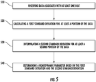
- Figure 5 presents an exemplary process flow or method for determining a hemodynamic parameter. This is the second method described previously. The second method is different from the first method primarily due to an interpolation step (see block 530 ).
- the process flow comprises receiving data associated with at least one heart beat.
- Receiving data associated with at least one heart beat may comprise measuring a waveform and identifying at least one heart beat using a digital signal processing algorithm.
- Receiving data may comprise measuring at least one arterial blood pressure waveform and identifying at least one heart beat.
- the data may comprise a blood pressure waveform.
- the blood pressure waveform corresponds to a signal, for example, from an arterial blood pressure, or any signal proportional to, or derived from the arterial pressure signal such as a pulse-oximetry signal, a Doppler ultrasound signal or a bioimpedance signal.
- the process flow comprises calculating a first standard deviation for at least a portion (or first portion) of the data.
- the process flow further comprises determining a polynomial function that fits the first standard deviation, wherein the polynomial function (e.g., 1 st order, 2 nd order, n th order, or any combination thereof) is associated with at least one polynomial coefficient.
- the polynomial function may be based on a least-squares function.
- the process flow comprises interpolating a second standard deviation for at least a second portion of the data (different from the first portion of the data). The interpolation may be performed based on the polynomial function. In some embodiments, the process flow further comprises subtracting the second standard deviation from the first standard deviation.
- the process flow comprises determining a hemodynamic parameter (e.g., associated with a non-respiration effect) based on the first standard deviation and the second standard deviation.
- the determining of the hemodynamic parameter may further be configured to determine the hemodynamic parameter based on multiplying the constant and the standard deviation of the second standard deviation to produce a first computation, and dividing the first computation by the mean of the first standard deviation. Constant is again an empirically determined or selected scaling constant.
- the operation of determining a polynomial function and the operation depicted at 540 can be replaced with using a Fourier transform and filtering scheme (e.g., high-pass filtering scheme) to remove at least a second portion of the data, and then using an inverse Fourier transform to obtain the second standard deviation for at least a second portion of the data.
- a Fourier transform and filtering scheme e.g., high-pass filtering scheme
- first standard deviation and second standard deviation are not used to indicate orders of standard deviation; instead, they are used to indicate a first standard deviation calculation and a second standard deviation calculation. Both the first standard deviation calculation and the second standard deviation calculation may be associated with any order of standard deviation.
- the received data (as indicated in block 510 ) of the second method changes depending on the hemodynamic parameter that is to be determined.
- blood pressure data comprising a blood pressure waveform
- the process flow comprises calculating a first standard deviation for at least a portion (or first portion) of the blood pressure data.
- the process flow comprises interpolating a second standard deviation for at least a second portion of the blood pressure data (different from the first portion of the blood pressure data).
- the process flow comprises determining the SVV based on the first standard deviation and the second standard deviation.
- systolic pressure data (comprising a systolic pressure waveform) is received at block 510.
- the process flow comprises calculating a first standard deviation for at least a portion (or first portion) of the systolic pressure data.
- the process flow comprises interpolating a second standard deviation for at least a second portion of the systolic pressure data (different from the first portion of the systolic pressure data).
- the process flow comprises determining the SPV based on the first standard deviation and the second standard deviation.
- pulse pressure data (comprising a pulse pressure waveform) is received at block 510.
- the process flow comprises calculating a first standard deviation for at least a portion (or first portion) of the pulse pressure data.
- the process flow comprises interpolating a second standard deviation for at least a second portion of the pulse pressure data (different from the first portion of the pulse pressure data).
- the process flow comprises determining the PPV based on the first standard deviation and the second standard deviation.
- pulse oximeter waveform data (comprising a pulse oximeter waveform) is received at block 510.
- the process flow comprises calculating a first standard deviation for at least a portion (or first portion) of the pulse oximeter waveform data.
- the process flow comprises interpolating a second standard deviation for at least a second portion of the pulse oximeter waveform data (different from the first portion of the pulse oximeter waveform data).
- the process flow comprises determining the PVI based on the first standard deviation and the second standard deviation.
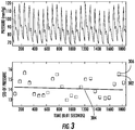
- Figure 3 shows an example of the second method using the pressure obtained before a bolus of phenylephrine is given to a patient.
- the SVV obtained with the first method and the second method are quite close, as expected, since in the second method, the variation of the stroke volume is mainly induced by the respiration effect.
- the top plot in Figure 3 illustrates blood pressure before a bolus phenylephrine is given to a patient.
- each circle e.g., circle 302
- the line 304 shows the fitted first order polynomial.
- Each square e.g., square 306
- Some circles are only partially visible or not visible because they at least partially overlap with some squares.
- the SVV calculated via the first and second methods are very close to each other. They are 17.03% and 17.04%, respectively.
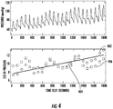
- Figure 4 shows an example of the second method using the pressure obtained after the bolus of phenylephrine is given to a patient.
- the SVV obtained with the first method and the second method are quite different, as expected, since in the second method, the variation of the stroke volume is induced not only by the respiration effect, but also by other non-respiration induced effect.
- the SVV calculated using the second method removes much of the non-respiration effect and its value is much closer to the true value.
- the top plot in Figure 4 shows the blood pressure after a bolus phenylephrine is given to a patient.
- each circle e.g., circle 402
- the line 404 shows the fitted first order polynomial.
- the square e.g., square 406
- Some circles are only partially visible or not visible because they at least partially overlap with some squares.
- the SVV calculated via the first and second methods are quite different. They are 44% and 24%, respectively.
- the first order polynomial fit in the second method can be replaced with other orders of polynomial fit, such as the 2nd order, the 3rd order, etc., or can also be replaced with combinations of orders of polynomial fit.
- the fit does not have to use all data points; instead, it can be among selected data points, such as the first several data points and/or the last several data points.
- Figure 6 presents another exemplary process flow for determining a hemodynamic parameter.
- the process flow comprises receiving a first portion of data associated with at least one heart beat.
- the process flow comprises interpolating a second portion of the data based on the first portion of the data.
- the process flow comprises calculating at least one standard deviation for at least one of the first portion of the data or the second portion of the data.
- the process flow comprises determining the hemodynamic parameter based on the at least one standard deviation.
- Each step of any process flow described herein may be performed by a single computing device processor or different computing device processors.
- the process flow in Figure 6 may be applicable to any hemodynamic parameter, including, but not limited to SVV, SPV, PPV, and PVI.
- Figure 7 shows a system that may be used to determine any hemodynamic parameter, including, but not limited to SVV, SPV, PPV, and PVI.
- Figure 7 shows two types of pressure sensing for the sake of conciseness; in most practical applications of the disclosure, either one or several variations will typically be implemented.
- a conventional pressure sensor 7100 e.g., a disposable pressure transducer
- a catheter 7110 which is inserted in an artery 7120 of a portion 7130 of the body of a human or animal patient.
- Such an artery could be an ascending aorta, or pulmonary artery, or, in order to reduce the level of invasiveness, the artery 7120 could be peripheral, such as the femoral, radial or brachial artery.
- a conventional pressure sensor 7200 such as a photo-plethysmographic blood pressure probe, is mounted externally in any conventional manner, for example using a cuff around a finger 7230 or a transducer mounted on the wrist of the patient.
- the sensor 7100 or 7200 may comprise a pressure transducer (e.g., a disposable pressure transducer DPT).
- Figure 7 schematically shows both types.
- the signals from the sensors 7100 , 7200 are passed via any known connectors as inputs to a processing system 7300 , which includes one or more processors and other supporting hardware and system software (not shown) usually included to process signals and execute code.
- the disclosure may be implemented using a modified, standard, personal computer, or it may be incorporated into a larger, specialized monitoring system.
- the processing system 7300 also may include, or is connected to, conditioning circuitry 7302 which performs such normal signal processing tasks as amplification, filtering, ranging, etc., as needed, as well as optional high pass filtering.
- the conditioned, sensed input pressure signal P(t) is then converted to digital form by a conventional analog-to-digital converter ADC 7304 , which has or takes its time reference from a clock circuit 7305.
- ADC 7304 the sampling frequency of the ADC 7304 should be chosen with regard to the Nyquist criterion so as to avoid aliasing of the pressure signal.
- the output from the ADC 7304 will be the discrete pressure signal P(k), whose values may be stored in conventional memory circuitry (not shown).
- the values P(k) are passed to (usually, accessed from memory by) to a software module 7310 comprising computer-executable code for computing whichever of the parameters are to be used in the chosen algorithm for calculating the K.
- the patient-specific data such as age, height, weight, body surface area, etc.
- a memory 7315 which may also store other predetermined parameters. These values may be entered using any known input device 7400 in the conventional manner.
- a compliance calculation module 7320 also comprising computer-executable code, then takes as inputs the various moment and patient-specific values and performs the chosen calculations for computing the arterial compliance function K (or compliance factor C). For example, the module 7320 could enter the parameters into the expression given below for K (or C), or into some other expression derived by creating an approximating function that best fits a set of test data.
- a stroke volume computation module 7330 again comprising computer-executable code, then computes an SV estimate.
- a CO computation module 7330 may then generate an estimate of CO using the method described herein.
- Additional software modules 7360 and 7370 may be included to perform the calculations described above to estimate the exponential pressure decay constant tau and vascular resistance R.
- the vascular resistance R may also be referred to as the systemic vascular resistance.
- Still additional software modules may be included to determine or calculate any hemodynamic parameter described herein, including, but not limited to, SVV, PPV, SPV, or PVI.
- the software modules 7320 , 7330 , 7350 , 7360 , and 7370 may be implemented within an estimation software component 317 , which may of course be combined with the moment-calculating component 7310 , or with other software components of the processing system 7300 as desired.
- any or all of the results K, SV, CO, tau and R may be passed to any conventional display or recording device 7500 for presentation to and interpretation by a user or another system.
- the display 7500 will typically be the same as is used by the processing system for other purposes.
- the disclosure further relates to a computer program loadable in a computer unit or the processing system 7300 in order to execute the methods of the disclosure.
- the various software modules 7310 , 7315 , 7320 , 7330 , 7340 , 7350 , 7360 , and 7370 used to perform the various calculations and perform related method steps according to the disclosure may also be stored as computer-executable instructions on a computer-readable medium in order to allow the instructions to be loaded into and executed by different processing systems.
- module with respect to an apparatus may refer to a hardware component of the apparatus, a software component of the apparatus, or a component of the apparatus that includes both hardware and software.
- a module may include one or more modules, where each module may reside in separate pieces of hardware or software.
- an apparatus may alternatively be referred to as a "system” or a “device.”
- the present disclosure may include and/or be embodied as an apparatus (including, for example, a system, apparatus, machine, device, computer program product, and/or the like), as a method (including, for example, a business method, computer-implemented process, and/or the like), or as any combination of the foregoing.
- examples of the present disclosure may take the form of an entirely business method, an entirely software example (including firmware, resident software, micro-code, stored procedures in a database, or the like), an entirely hardware example, or an example combining business method, software, and hardware aspects that may generally be referred to herein as a "system” or "apparatus.”
- examples of the present disclosure may take the form of a computer program product that includes a computer-readable storage medium having one or more computer-executable program code portions stored therein.
- a processor which may include one or more processors, may be "configured to" perform a certain function in a variety of ways, including, for example, by having one or more general-purpose circuits perform the function by executing one or more computer-executable program code portions embodied in a computer-readable medium, and/or by having one or more application-specific circuits perform the function.
- the computer-readable medium may include, but is not limited to, a non-transitory computer-readable medium, such as a tangible electronic, magnetic, optical, electromagnetic, infrared, and/or semiconductor system, device, and/or other apparatus.
- a non-transitory computer-readable medium such as a tangible electronic, magnetic, optical, electromagnetic, infrared, and/or semiconductor system, device, and/or other apparatus.
- the non-transitory computer-readable medium includes a tangible medium such as a portable computer diskette, a hard disk, a random access memory (RAM), a read-only memory (ROM), an erasable programmable read-only memory (EPROM or Flash memory), a compact disc read-only memory (CD-ROM), and/or some other tangible optical and/or magnetic storage device.
- the computer-readable medium may be transitory, such as, for example, a propagation signal including computer-executable program code portions embodied therein.
- One or more computer-executable program code portions for carrying out operations of the present disclosure may include object-oriented, scripted, and/or unscripted programming languages, such as, for example, Java, Perl, Smalltalk, C++, SAS, SQL, Python, Objective C, JavaScript, and/or the like.
- the one or more computer-executable program code portions for carrying out operations of the present disclosure can be written in conventional procedural programming languages, such as the "C" programming languages and/or similar programming languages.
- the computer program code may alternatively or additionally be written in one or more multi-paradigm programming languages, such as, for example, F#.
- These one or more computer-executable program code portions may be provided to a processor of a general purpose computer, special purpose computer, and/or some other programmable data processing apparatus in order to produce a particular machine, such that the one or more computer-executable program code portions, which execute via the processor of the computer and/or other programmable data processing apparatus, create mechanisms for implementing the steps and/or functions represented by the flowchart(s) and/or block diagram block(s).
- the one or more computer-executable program code portions may be stored in a transitory and/or non-transitory computer-readable medium (e.g., a memory or the like) that can direct, instruct, and/or cause a computer and/or other programmable data processing apparatus to function in a particular manner, such that the computer-executable program code portions stored in the computer-readable medium produce an article of manufacture including instruction mechanisms which implement the steps and/or functions specified in the flowchart(s) and/or block diagram block(s).
- a transitory and/or non-transitory computer-readable medium e.g., a memory or the like
- the one or more computer-executable program code portions may also be loaded onto a computer and/or other programmable data processing apparatus to cause a series of operational steps to be performed on the computer and/or other programmable apparatus.
- This can produce a computer-implemented process such that the one or more computer-executable program code portions which execute on the computer and/or other programmable apparatus provide operational steps to implement the steps specified in the flowchart(s) and/or the functions specified in the block diagram block(s).
- computer-implemented steps may be combined with, and/or replaced with, operator- and/or human-implemented steps in order to carry out the present disclosure.
Description
- This disclosure is related to the field of patient hemodynamic monitoring and digital signal processing. This disclosure specifically relates to a method of calculating real-time hemodynamic parameters.
- Indicators such as stroke volume (SV), cardiac output (CO), end-diastolic volume, ejection fraction, stroke volume variation (SVV), pulse pressure variation (PPV), systolic pressure variations (SPV), and plethysmographic variability index (PVI), among others, are important not only for diagnosis of disease, but also for "real-time" monitoring of preload dependence, fluid responsiveness, or volume responsiveness condition of both human and animal subjects. Few hospitals are therefore without some form of equipment to monitor one or more of these cardiac parameters. Many techniques, including invasive techniques, non-invasive techniques, and combinations thereof, are in use and even more have been proposed in the literature. References that disclose determination of hemodynamic parameters include
WO2011094487 (Jian et al., filed 28 Jan., 2011 ) andWO 2009023713 (Derderian et al., filed 13 Aug., 2008 ). - One way to obtain a hemodynamic parameter is to mount a flow-measuring device on a catheter, and position the device in or near the subject's heart. Some such devices inject either a bolus of material or energy (usually heat) at an upstream position, such as in the right atrium, and determine flow based on the characteristics of the injected material or energy at a downstream position, such as in the pulmonary artery. Patents that disclose implementations of such invasive techniques (in particular, thermodilution) include:
U.S. Pat. No. 4,236,527 (Newbower et al., 2 Dec. 1980 );U.S. Pat. No. 4,507,974 (Yelderman, 2 Apr. 1985 );U.S. Pat. No. 5,146,414 (McKown, et al., 8 Sep. 1992 ); andU.S. Pat. No. 5,687,733 (McKown, et al., 18 Nov. 1997 ). Other invasive devices are based on the known Fick technique, according to which a hemodynamic parameter is calculated as a function of oxygenation of arterial and mixed venous blood. Doppler techniques, using invasive as well as non-invasive transducers, have also been used to obtain flow rate data that can then be used to calculate a hemodynamic parameter. - One blood characteristic that can be obtained with minimal or no invasion is blood pressure. In addition to causing minimal patient trauma, blood pressure measurement technology has the added benefit of being accurate and continuous. Many systems rely on the pulse contour method (PCM), which calculates an estimate of one or more hemodynamic parameters of interest from characteristics of a blood pressure waveform. In the PCM, "Windkessel" parameters, such as characteristic impedance of the aorta, compliance, and total peripheral resistance, are often used to construct a linear or non- linear hemodynamic model of the aorta. In essence, blood flow is analogized to a flow of electrical current in a circuit in which an impedance is in series with a parallel-connected resistance and capacitance (compliance). The three required parameters of the model are usually determined either empirically, through a complex calibration process, or from compiled "anthropometric" data, i.e., data about the age, sex, height, weight, and/or other parameters of other patients or test subjects.
U.S. Pat. No. 5,400,793 (Wesseling, 28 Mar. 1995 ) andU.S. Pat. No. 5,535,753 (Petrucelli et al., 16 Jul. 1996 ) disclose systems that rely on a Windkessel circuit model to determine a hemodynamic parameter. PCM-based systems can monitor hemodynamic parameters using blood pressure measurements taken using a variety of measurement apparatus, such as a finger cuff, and can do so more or less continuously. Many improvements, with varying degrees of complexity, have been proposed for improving the accuracy of the basic PCM model. The present disclosure offers an improvement over the PCM model or any other models discussed in this section. - Yet more advanced methods for calculating hemodynamic parameters are described, for example, in United States Patent Nos.
7,967,757 , and8,721,556 , in PCT patent application publication numbersWO2009/023713 WO2011/094487 , andWO2015/006191 . - "Getting ml/beat from mmHg Arterial Pressure-based Cardiac Output The Edwards FloTrac Algorithm" by Frazier J et al discloses the FloTrac algorithm, an arterial pressure-based cardiac output (APCO) method in which cardiac output can be continuously measured real time using an arterial catheter.
-
WO2005/055825 A1 discloses one or more cardiovascular parameters which are estimated as a function of the arterial pressure waveform, in particular, using at least one statistical moment of a discrete representation pressure waveform having an order greater than one. Arterial pressure may be measured invasively or non-invasively. Arterial compliance, an exponential pressure decay constant, vascular resistance, cardiac output, and stroke volume are examples of cardiovascular parameters that can be estimated using various aspects of the invention. In a single-moment embodiment, cardiac stroke volume of a subject is estimated as a function of a value derived from the pressure waveform. In a multi-moment embodiment, two or more of the first four moments - mean, standard deviation, skewness, and kurtosis - of the pressure waveform are used to estimate the cardiovascular parameter(s) of interest, as well as heart rate, statistical moments of a set of pressure-weighted time values, and certain anthropometric patient measurements such as age, sex, body surface area, etc. -
US 2005/187481 A1 discloses a method and system for determining the stroke volume variation from a blood pressure data trace. - The present invention is defined by the appended claims and relates to a method and an apparatus for determining a hemodynamic parameter, according to
independent claims 1 and 10, respectively. - The hemodynamic parameter may comprise a stroke volume variation (SVV), and the data comprises blood pressure data.
- The hemodynamic parameter may comprise a pulse pressure variation (PPV), and the data comprises pulse pressure data.
- The hemodynamic parameter may comprise a systolic pressure variation (SPV), and the data comprises systolic pressure data.
- The hemodynamic parameter may comprise a plethysmographic variability index (PVI), and the data comprises pulse oximeter waveform data.
- The method comprises determining, using a computing device processor, a polynomial function that fits the first standard deviation, the polynomial function being associated with at least one polynomial coefficient.
- The polynomial function may be based on a least-squares function.
- Receiving data may comprise measuring at least one arterial blood pressure waveform and identifying the at least one heart beat.
- The method further comprises subtracting the polynomial function from the first standard deviation.
- Determining the hemodynamic parameter may further comprise determining the hemodynamic parameter based on a constant, a standard deviation of the second standard deviation, and a mean of the first standard deviation.
- Determining the hemodynamic parameter may further comprise determining the hemodynamic parameter based on multiplying the constant and the standard deviation of the second standard deviation to produce a first computation, and dividing the first computation by the mean of the first standard deviation.
- The polynomial function may be a first order polynomial function.
- The polynomial function may be an nth order polynomial function.
- An exemplary computer program product for determining a hemodynamic parameter, useful for understanding the present invention, comprises a non-transitory computer-readable medium comprising a set of codes for causing a computer to: receive data associated with at least one heart beat; calculate a first standard deviation for at least a portion of the data; interpolate a second standard deviation for at least a second portion of the data; and determine the hemodynamic parameter based on the first standard deviation and the second standard deviation.
- Another exemplary apparatus for determining a hemodynamic parameter, useful for understanding the present invention, comprises means for receiving data associated with at least one heart beat; means for calculating a first standard deviation for at least a portion of the data; means for interpolating a second standard deviation for at least a second portion of the data; and means for determining the hemodynamic parameter based on the first standard deviation and the second standard deviation.
- Another method for determining a hemodynamic parameter, useful for understanding the present invention, comprises: receiving data associated with at least one heart beat; calculating a first standard deviation for at least a portion of the data; using a Fourier transform and filtering scheme to remove at least a second portion of the data; using an inverse Fourier transform to obtain a second standard deviation for at least a second portion of the data; and determining, using a computing device processor, the hemodynamic parameter based on the first standard deviation and the second standard deviation. Apparatus and computer program product may also be provided based on this method.
- Yet another method for determining a hemodynamic parameter, useful for understanding the present invention, comprises: receiving a first portion of data associated with at least one heart beat; interpolating a second portion of the data based on the first portion of the data; calculating at least one standard deviation for at least one of the first portion of the data or the second portion of the data; and determining, using a computing device processor, the hemodynamic parameter based on the at least one standard deviation. In some embodiments, the hemodynamic parameter comprises at least one of SVV, PPV, SPV, or PVI. Apparatus and computer program product may also be provided based on this method.
- Reference will now be made to the accompanying drawings, where:
-
Figure 1 shows an example of radial artery pressure before a bolus vasopressor of phenylephrine is given to patients; -
Figure 2 shows an example of radial artery pressure after a bolus vasopressor of phenylephrine is given to patients; -
Figure 3 shows an example of a hemodynamic parameter determination method using the pressure obtained before the bolus of phenylephrine is given to a patient; -
Figure 4 shows an example of a hemodynamic parameter determination method using the pressure obtained after the bolus of phenylephrine is given to a patient; -
Figure 5 shows an exemplary method for determining a hemodynamic parameter; -
Figure 6 shows another exemplary method for determining a hemodynamic parameter; and -
Figure 7 shows an exemplary apparatus for determining a hemodynamic parameter. - Embodiments of the present disclosure now may be described more fully hereinafter with reference to the accompanying drawings, in which some, but not all, embodiments of the disclosure are shown. Indeed, the disclosure may be embodied in many different forms and should not be construed as limited to the embodiments set forth herein; rather, these embodiments are provided so that this disclosure may satisfy applicable legal requirements. Like numbers refer to like elements throughout.
- The disclosure is directed to apparatuses, methods and computer program products for determining or calculating a hemodynamic parameter. This disclosure provides a new method to calculate hemodynamic parameters such as stroke volume variation (SVV), pulse pressure variation (PPV), systolic pressure variation (SPV), and plethysmographic variability index (PVI) based on blood pressure waveforms. In today's patient hemodynamic monitoring, blood pressure is routinely monitored and many parameters that are of great clinical use, such as cardiac output, stroke volume, and stroke volume variation can be derived from blood pressure waveforms and displayed by monitors. Accurately calculating those parameters is of great importance because accurate calculations can help clinicians know more about patients and make more informed decisions in treating patients.
- Exemplary methods of the present disclosure are directed to determining SVV. However, these methods or variations of these methods may be used to determine other hemodynamic parameters, including, but not limited to, SPV, PPV, or PVI. A method for calculating SVV, which is induced by mechanical ventilation, predicts fluid responsiveness with high sensitivity and specificity. As a result, it is often used by clinicians as a guide for fluid optimization. The SVV may be calculated using the formula: SVV = constant x std(std bp) / mean(std bp), where constant is a constant parameter, std is the standard deviation, std_bp is an array of the standard deviation of each beat in a 20 second window, and mean is the average value (e.g., average value of std bp). Constant is an empirically determined scaling constant, which can be chosen largely for convenience and as appropriate for display to a user of a system embodying and performing the method. A suitable scaling constant might be 2.7, for example. Regardless of the number of respiratory cycles included in the computation interval; normal experimental methods may be used to determine a suitable scaling constant in any given implementation of the invention. This method of calculation or determination of the SVV may be referred to as the first method. The first method does reasonably well in predicting fluid responsiveness. The issue of this method, however, is that it does not completely distinguish the variation of stroke volume due to the mechanical ventilation from variation due to other causes. As a result, the first method may not predict fluid responsiveness with high accuracy (e.g., accuracy equal to or greater than a threshold accuracy).
-
Figure 1 shows an example of radial artery pressure before a bolus vasopressor of phenylephrine is given to patients. The top plot shows the pressure and the bottom plot shows the standard deviation of blood pressure in each beat. The respiration-induced variation of stroke volume can be clearly observed in both plots ofFigure 1 . -
Figure 2 shows an example of radial artery pressure after a bolus vasopressor of phenylephrine is given to patients. The top plot shows the pressure and the bottom plot shows the standard deviation of blood pressure in each beat. The respiration-induced variation of stroke volume can be observed, but in addition to that, it comes with a significant change of stroke volume induced by the bolus phenylephrine. - The present disclosure is directed to a second method to determine a hemodynamic parameter such as SVV. This method removes many of the variations of stroke volume due to other sources from the determination, thus improving the sensitivity and specificity of the SVV's or any other hemodynamic parameter's ability in predicting fluid responsiveness.
-
Figure 5 presents an exemplary process flow or method for determining a hemodynamic parameter. This is the second method described previously. The second method is different from the first method primarily due to an interpolation step (see block 530). Atblock 510, the process flow comprises receiving data associated with at least one heart beat. Receiving data associated with at least one heart beat may comprise measuring a waveform and identifying at least one heart beat using a digital signal processing algorithm. Receiving data may comprise measuring at least one arterial blood pressure waveform and identifying at least one heart beat. As indicated previously, the data may comprise a blood pressure waveform. The blood pressure waveform corresponds to a signal, for example, from an arterial blood pressure, or any signal proportional to, or derived from the arterial pressure signal such as a pulse-oximetry signal, a Doppler ultrasound signal or a bioimpedance signal. Atblock 520, the process flow comprises calculating a first standard deviation for at least a portion (or first portion) of the data. - The process flow further comprises determining a polynomial function that fits the first standard deviation, wherein the polynomial function (e.g., 1st order, 2nd order, nth order, or any combination thereof) is associated with at least one polynomial coefficient. The polynomial function may be based on a least-squares function. At
block 530, the process flow comprises interpolating a second standard deviation for at least a second portion of the data (different from the first portion of the data). The interpolation may be performed based on the polynomial function. In some embodiments, the process flow further comprises subtracting the second standard deviation from the first standard deviation. - At
block 540, the process flow comprises determining a hemodynamic parameter (e.g., associated with a non-respiration effect) based on the first standard deviation and the second standard deviation. The determining of the hemodynamic parameter may further be configured to determine the hemodynamic parameter based on multiplying the constant and the standard deviation of the second standard deviation to produce a first computation, and dividing the first computation by the mean of the first standard deviation. Constant is again an empirically determined or selected scaling constant. The operation of determining a polynomial function and the operation depicted at 540 can be replaced with using a Fourier transform and filtering scheme (e.g., high-pass filtering scheme) to remove at least a second portion of the data, and then using an inverse Fourier transform to obtain the second standard deviation for at least a second portion of the data. As used herein, "first" standard deviation and "second" standard deviation are not used to indicate orders of standard deviation; instead, they are used to indicate a first standard deviation calculation and a second standard deviation calculation. Both the first standard deviation calculation and the second standard deviation calculation may be associated with any order of standard deviation. - The received data (as indicated in block 510) of the second method changes depending on the hemodynamic parameter that is to be determined. When determining SVV, for example, blood pressure data (comprising a blood pressure waveform) is received at
block 510. Atblock 520, the process flow comprises calculating a first standard deviation for at least a portion (or first portion) of the blood pressure data. Atblock 530, the process flow comprises interpolating a second standard deviation for at least a second portion of the blood pressure data (different from the first portion of the blood pressure data). Atblock 540, the process flow comprises determining the SVV based on the first standard deviation and the second standard deviation. - When determining SPV, systolic pressure data (comprising a systolic pressure waveform) is received at
block 510. Atblock 520, the process flow comprises calculating a first standard deviation for at least a portion (or first portion) of the systolic pressure data. Atblock 530, the process flow comprises interpolating a second standard deviation for at least a second portion of the systolic pressure data (different from the first portion of the systolic pressure data). Atblock 540, the process flow comprises determining the SPV based on the first standard deviation and the second standard deviation. - When determining PPV, pulse pressure data (comprising a pulse pressure waveform) is received at
block 510. Atblock 520, the process flow comprises calculating a first standard deviation for at least a portion (or first portion) of the pulse pressure data. Atblock 530, the process flow comprises interpolating a second standard deviation for at least a second portion of the pulse pressure data (different from the first portion of the pulse pressure data). Atblock 540, the process flow comprises determining the PPV based on the first standard deviation and the second standard deviation. - When determining PVI, pulse oximeter waveform data (comprising a pulse oximeter waveform) is received at
block 510. Atblock 520, the process flow comprises calculating a first standard deviation for at least a portion (or first portion) of the pulse oximeter waveform data. Atblock 530, the process flow comprises interpolating a second standard deviation for at least a second portion of the pulse oximeter waveform data (different from the first portion of the pulse oximeter waveform data). Atblock 540, the process flow comprises determining the PVI based on the first standard deviation and the second standard deviation. -
Figure 3 shows an example of the second method using the pressure obtained before a bolus of phenylephrine is given to a patient. The SVV obtained with the first method and the second method are quite close, as expected, since in the second method, the variation of the stroke volume is mainly induced by the respiration effect. - The top plot in
Figure 3 illustrates blood pressure before a bolus phenylephrine is given to a patient. In the bottom plot ofFigure 3 , each circle (e.g., circle 302) shows the original standard deviation of blood pressure of each beat. Theline 304 shows the fitted first order polynomial. Each square (e.g., square 306) shows the new standard deviation of blood pressure of each beat, obtained by subtracting theline 304 from the original standard deviation. Some circles are only partially visible or not visible because they at least partially overlap with some squares. The SVV calculated via the first and second methods are very close to each other. They are 17.03% and 17.04%, respectively. -
Figure 4 shows an example of the second method using the pressure obtained after the bolus of phenylephrine is given to a patient. The SVV obtained with the first method and the second method are quite different, as expected, since in the second method, the variation of the stroke volume is induced not only by the respiration effect, but also by other non-respiration induced effect. The SVV calculated using the second method removes much of the non-respiration effect and its value is much closer to the true value. - The top plot in
Figure 4 shows the blood pressure after a bolus phenylephrine is given to a patient. In the bottom plot ofFigure 4 , each circle (e.g., circle 402) shows the original standard deviation of blood pressure of each beat. Theline 404 shows the fitted first order polynomial. The square (e.g., square 406) shows the new standard deviation of blood pressure of each beat, obtained by subtracting theline 404 from the original standard deviation. Some circles are only partially visible or not visible because they at least partially overlap with some squares. The SVV calculated via the first and second methods are quite different. They are 44% and 24%, respectively. - The first order polynomial fit in the second method can be replaced with other orders of polynomial fit, such as the 2nd order, the 3rd order, etc., or can also be replaced with combinations of orders of polynomial fit. The fit does not have to use all data points; instead, it can be among selected data points, such as the first several data points and/or the last several data points.
- Referring now to
Figure 6, Figure 6 presents another exemplary process flow for determining a hemodynamic parameter. Atblock 610, the process flow comprises receiving a first portion of data associated with at least one heart beat. Atblock 620, the process flow comprises interpolating a second portion of the data based on the first portion of the data. Atblock 630, the process flow comprises calculating at least one standard deviation for at least one of the first portion of the data or the second portion of the data. Atblock 640, the process flow comprises determining the hemodynamic parameter based on the at least one standard deviation. Each step of any process flow described herein may be performed by a single computing device processor or different computing device processors. Some of the steps may be performed by a single computing device processor, while other steps may be performed by individual computing device processors. Similar toFigure 5 , the process flow inFigure 6 may be applicable to any hemodynamic parameter, including, but not limited to SVV, SPV, PPV, and PVI. - Referring now to
Figure 7, Figure 7 shows a system that may be used to determine any hemodynamic parameter, including, but not limited to SVV, SPV, PPV, and PVI.Figure 7 shows two types of pressure sensing for the sake of conciseness; in most practical applications of the disclosure, either one or several variations will typically be implemented. In invasive applications of the disclosure, a conventional pressure sensor 7100 (e.g., a disposable pressure transducer) is mounted on acatheter 7110, which is inserted in anartery 7120 of aportion 7130 of the body of a human or animal patient. Such an artery could be an ascending aorta, or pulmonary artery, or, in order to reduce the level of invasiveness, theartery 7120 could be peripheral, such as the femoral, radial or brachial artery. In the non-invasive applications of the disclosure, aconventional pressure sensor 7200, such as a photo-plethysmographic blood pressure probe, is mounted externally in any conventional manner, for example using a cuff around afinger 7230 or a transducer mounted on the wrist of the patient. Thesensor Figure 7 schematically shows both types. - The signals from the
sensors processing system 7300, which includes one or more processors and other supporting hardware and system software (not shown) usually included to process signals and execute code. The disclosure may be implemented using a modified, standard, personal computer, or it may be incorporated into a larger, specialized monitoring system. In this disclosure, theprocessing system 7300 also may include, or is connected to,conditioning circuitry 7302 which performs such normal signal processing tasks as amplification, filtering, ranging, etc., as needed, as well as optional high pass filtering. The conditioned, sensed input pressure signal P(t) is then converted to digital form by a conventional analog-to-digital converter ADC 7304, which has or takes its time reference from aclock circuit 7305. As is well understood, the sampling frequency of theADC 7304 should be chosen with regard to the Nyquist criterion so as to avoid aliasing of the pressure signal. The output from theADC 7304 will be the discrete pressure signal P(k), whose values may be stored in conventional memory circuitry (not shown). - The values P(k) are passed to (usually, accessed from memory by) to a
software module 7310 comprising computer-executable code for computing whichever of the parameters are to be used in the chosen algorithm for calculating the K. - The patient-specific data such as age, height, weight, body surface area, etc., is stored in a
memory 7315, which may also store other predetermined parameters. These values may be entered using any knowninput device 7400 in the conventional manner. - A
compliance calculation module 7320, also comprising computer-executable code, then takes as inputs the various moment and patient-specific values and performs the chosen calculations for computing the arterial compliance function K (or compliance factor C). For example, themodule 7320 could enter the parameters into the expression given below for K (or C), or into some other expression derived by creating an approximating function that best fits a set of test data. Thecalculation module 7320 preferably also selects the time window over which each K, C, SV, CO, SVV, SPV, PPV, and/or PVI estimate is generated. This may be done as simply as choosing which and how many of the stored, consecutive, discretized P(t) values P(k) are used in each calculation, which is the same as selecting n in the range k=0, ... , (n-1). - Taking K (and other parameters such as C) as inputs, a stroke
volume computation module 7330, again comprising computer-executable code, then computes an SV estimate. Taking as inputs both SV and a heart rate value HR generated by any knownhardware device 7340 or software routine (for example, using Fourier or derivative analysis) for measuring heart rate along with any other parameters described herein, aCO computation module 7330 may then generate an estimate of CO using the method described herein. -
Additional software modules - As shown in
Figure 7 , thesoftware modules component 7310, or with other software components of theprocessing system 7300 as desired. - It is not necessary for the system to compute SV or CO if these values are not of interest. The same is true for tau and R. In such case, the corresponding software modules will of course not be needed and may be omitted. For example, the disclosure could be used in a study of arterial compliance itself. Nonetheless, as
Figure 7 illustrates, any or all of the results K, SV, CO, tau and R may be passed to any conventional display orrecording device 7500 for presentation to and interpretation by a user or another system. As with theinput device 7400, thedisplay 7500 will typically be the same as is used by the processing system for other purposes. - The disclosure further relates to a computer program loadable in a computer unit or the
processing system 7300 in order to execute the methods of the disclosure. Moreover, the various software
modules - In accordance with the disclosure, the term "module" with respect to an apparatus may refer to a hardware component of the apparatus, a software component of the apparatus, or a component of the apparatus that includes both hardware and software. As used herein, a module may include one or more modules, where each module may reside in separate pieces of hardware or software. As used herein, an apparatus may alternatively be referred to as a "system" or a "device."
- Although many examples and embodiments of the present disclosure have just been described above, the present disclosure may be embodied in many different forms and should not be construed as limited to the examples and embodiments set forth herein; rather, these examples and embodiments are provided so that this disclosure will satisfy applicable legal requirements. Also, it will be understood that, where possible, any of the advantages, features, functions, devices, and/or operational aspects of any of the examples and embodiments of the present disclosure described and/or contemplated herein may be included in any of the other examples and embodiments of the present disclosure described and/or contemplated herein, and/or vice versa. In addition, where possible, any terms expressed in the singular form herein are meant to also include the plural form and/or vice versa, unless explicitly stated otherwise. Accordingly, the terms "a" and/or "an" shall mean "one or more," even though the phrase "one or more" is also used herein. Like numbers refer to like elements throughout.
- As will be appreciated by one of ordinary skill in the art in view of this disclosure, the present disclosure may include and/or be embodied as an apparatus (including, for example, a system, apparatus, machine, device, computer program product, and/or the like), as a method (including, for example, a business method, computer-implemented process, and/or the like), or as any combination of the foregoing. Accordingly, examples of the present disclosure may take the form of an entirely business method, an entirely software example (including firmware, resident software, micro-code, stored procedures in a database, or the like), an entirely hardware example, or an example combining business method, software, and hardware aspects that may generally be referred to herein as a "system" or "apparatus." Furthermore, examples of the present disclosure may take the form of a computer program product that includes a computer-readable storage medium having one or more computer-executable program code portions stored therein. As used herein, a processor, which may include one or more processors, may be "configured to" perform a certain function in a variety of ways, including, for example, by having one or more general-purpose circuits perform the function by executing one or more computer-executable program code portions embodied in a computer-readable medium, and/or by having one or more application-specific circuits perform the function.
- It will be understood that any suitable computer-readable medium may be utilized. The computer-readable medium may include, but is not limited to, a non-transitory computer-readable medium, such as a tangible electronic, magnetic, optical, electromagnetic, infrared, and/or semiconductor system, device, and/or other apparatus. For example, the non-transitory computer-readable medium includes a tangible medium such as a portable computer diskette, a hard disk, a random access memory (RAM), a read-only memory (ROM), an erasable programmable read-only memory (EPROM or Flash memory), a compact disc read-only memory (CD-ROM), and/or some other tangible optical and/or magnetic storage device. Alternatively, however, the computer-readable medium may be transitory, such as, for example, a propagation signal including computer-executable program code portions embodied therein.
- One or more computer-executable program code portions for carrying out operations of the present disclosure may include object-oriented, scripted, and/or unscripted programming languages, such as, for example, Java, Perl, Smalltalk, C++, SAS, SQL, Python, Objective C, JavaScript, and/or the like. The one or more computer-executable program code portions for carrying out operations of the present disclosure can be written in conventional procedural programming languages, such as the "C" programming languages and/or similar programming languages. The computer program code may alternatively or additionally be written in one or more multi-paradigm programming languages, such as, for example, F#.
- Some embodiments of the present disclosure are described herein with reference to flowchart illustrations and/or block diagrams of apparatus and/or methods. It will be understood that each block included in the flowchart illustrations and/or block diagrams, and/or combinations of blocks included in the flowchart illustrations and/or block diagrams, may be implemented by one or more computer-executable program code portions. These one or more computer-executable program code portions may be provided to a processor of a general purpose computer, special purpose computer, and/or some other programmable data processing apparatus in order to produce a particular machine, such that the one or more computer-executable program code portions, which execute via the processor of the computer and/or other programmable data processing apparatus, create mechanisms for implementing the steps and/or functions represented by the flowchart(s) and/or block diagram block(s).
- The one or more computer-executable program code portions may be stored in a transitory and/or non-transitory computer-readable medium (e.g., a memory or the like) that can direct, instruct, and/or cause a computer and/or other programmable data processing apparatus to function in a particular manner, such that the computer-executable program code portions stored in the computer-readable medium produce an article of manufacture including instruction mechanisms which implement the steps and/or functions specified in the flowchart(s) and/or block diagram block(s).
- The one or more computer-executable program code portions may also be loaded onto a computer and/or other programmable data processing apparatus to cause a series of operational steps to be performed on the computer and/or other programmable apparatus. This can produce a computer-implemented process such that the one or more computer-executable program code portions which execute on the computer and/or other programmable apparatus provide operational steps to implement the steps specified in the flowchart(s) and/or the functions specified in the block diagram block(s). Alternatively, computer-implemented steps may be combined with, and/or replaced with, operator- and/or human-implemented steps in order to carry out the present disclosure.
Claims (10)
- A method for determining a hemodynamic parameter, the method comprising:receiving data associated with at least one heart beat;calculating a first standard deviation for the data;determining, using a computing device processor, a polynomial function that fits the first standard deviation, the polynomial function being associated with at least one polynomial coefficient; characterised in that the method further comprisescalculating a second standard deviation by subtracting the polynomial function from the first standard deviation; anddetermining, using a computing device processor, the hemodynamic parameter based on the first standard deviation and the second standard deviation.
- The method of claim 1, wherein the hemodynamic parameter comprises a stroke volume variation, and wherein the data comprises blood pressure data.
- The method of claim 1, wherein the hemodynamic parameter comprises a pulse pressure variation, and wherein the data comprises pulse pressure data.
- The method of claim 1, wherein the hemodynamic parameter comprises a systolic pressure variation, and wherein the data comprises systolic pressure data.
- The method of claim 1, wherein the hemodynamic parameter comprises a plethysmographic variability index, and wherein the data comprises pulse oximeter waveform data.
- The method of claim 1, wherein the polynomial function is based on a least-squares function.
- The method of claim 1, wherein the determining of the hemodynamic parameter further comprises determining the hemodynamic parameter based on a constant, a standard deviation of the second standard deviation, and a mean of the first standard deviation.
- The method of claim 7, wherein the determining of the hemodynamic parameter further comprises determining the hemodynamic parameter based on multiplying the constant and the standard deviation of the second standard deviation to produce a first computation, and dividing the first computation by the mean of the first standard deviation.
- The method of claim 1, wherein the polynomial function is an nth order polynomial function.
- An apparatus for determining a hemodynamic parameter, the apparatus comprising:a communication interface;a memory;a processor; anda module stored in the memory, executable by the processor, and configured to perform the method of any one of claims 1 to 9.
Priority Applications (1)
| Application Number | Priority Date | Filing Date | Title |
|---|---|---|---|
| EP16202415.2A EP3170447A1 (en) | 2013-07-08 | 2014-07-08 | A method for determining a mechanical-respiration-induced variation in a cardiovascular parameter |
Applications Claiming Priority (2)
| Application Number | Priority Date | Filing Date | Title |
|---|---|---|---|
| US201361843722P | 2013-07-08 | 2013-07-08 | |
| PCT/US2014/045701 WO2015006295A1 (en) | 2013-07-08 | 2014-07-08 | Determination of a hemodynamic parameter |
Related Child Applications (2)
| Application Number | Title | Priority Date | Filing Date |
|---|---|---|---|
| EP16202415.2A Division-Into EP3170447A1 (en) | 2013-07-08 | 2014-07-08 | A method for determining a mechanical-respiration-induced variation in a cardiovascular parameter |
| EP16202415.2A Division EP3170447A1 (en) | 2013-07-08 | 2014-07-08 | A method for determining a mechanical-respiration-induced variation in a cardiovascular parameter |
Publications (3)
| Publication Number | Publication Date |
|---|---|
| EP3019075A1 EP3019075A1 (en) | 2016-05-18 |
| EP3019075A4 EP3019075A4 (en) | 2017-02-22 |
| EP3019075B1 true EP3019075B1 (en) | 2020-03-25 |
Family
ID=52280511
Family Applications (2)
| Application Number | Title | Priority Date | Filing Date |
|---|---|---|---|
| EP14822728.3A Active EP3019075B1 (en) | 2013-07-08 | 2014-07-08 | Determination of a hemodynamic parameter |
| EP16202415.2A Withdrawn EP3170447A1 (en) | 2013-07-08 | 2014-07-08 | A method for determining a mechanical-respiration-induced variation in a cardiovascular parameter |
Family Applications After (1)
| Application Number | Title | Priority Date | Filing Date |
|---|---|---|---|
| EP16202415.2A Withdrawn EP3170447A1 (en) | 2013-07-08 | 2014-07-08 | A method for determining a mechanical-respiration-induced variation in a cardiovascular parameter |
Country Status (3)
| Country | Link |
|---|---|
| US (1) | US10610166B2 (en) |
| EP (2) | EP3019075B1 (en) |
| WO (1) | WO2015006295A1 (en) |
Families Citing this family (4)
| Publication number | Priority date | Publication date | Assignee | Title |
|---|---|---|---|---|
| DE102015116655A1 (en) | 2015-10-01 | 2017-04-06 | Claas Selbstfahrende Erntemaschinen Gmbh | Harvester |
| GB2557199B (en) | 2016-11-30 | 2020-11-04 | Lidco Group Plc | Haemodynamic monitor with improved filtering |
| EP3342332B1 (en) * | 2016-12-28 | 2024-03-13 | Samsung Electronics Co., Ltd. | Adaptive bio-signal feature combining apparatus and method |
| US20200100686A1 (en) * | 2017-01-04 | 2020-04-02 | Koninklijke Philips N.V. | Device, system and method for determining pulse pressure variation of a subject |
Citations (1)
| Publication number | Priority date | Publication date | Assignee | Title |
|---|---|---|---|---|
| US20050187481A1 (en) * | 2003-12-05 | 2005-08-25 | Feras Hatib | Real-time measurement of ventricular stroke volume variations by continuous arterial pulse contour analysis |
Family Cites Families (20)
| Publication number | Priority date | Publication date | Assignee | Title |
|---|---|---|---|---|
| US4236527A (en) | 1978-10-20 | 1980-12-02 | Massachusetts General Hospital | Cardiac output detection by multiple frequency thermodilution |
| US4507974A (en) | 1983-04-21 | 1985-04-02 | The Board Of Trustees Of The Leland Stanford Jr. University | Method and apparatus for measuring flow |
| US5146414A (en) | 1990-04-18 | 1992-09-08 | Interflo Medical, Inc. | Method and apparatus for continuously measuring volumetric flow |
| NL9100150A (en) | 1991-01-29 | 1992-08-17 | Tno | METHOD FOR DETERMINING THE BATTLE VOLUME AND THE HEART MINUTE VOLUME OF THE HUMAN HEART. |
| US5535753A (en) | 1994-10-04 | 1996-07-16 | Rutgers University | Apparatus and methods for the noninvasive measurement of cardiovascular system parameters |
| US5687733A (en) | 1995-10-26 | 1997-11-18 | Baxter International Inc. | System and method for estimating cardiac output |
| US6554774B1 (en) | 2000-03-23 | 2003-04-29 | Tensys Medical, Inc. | Method and apparatus for assessing hemodynamic properties within the circulatory system of a living subject |
| US6945939B2 (en) * | 2002-10-18 | 2005-09-20 | Pacesetter, Inc. | Hemodynamic analysis |
| US7220230B2 (en) | 2003-12-05 | 2007-05-22 | Edwards Lifesciences Corporation | Pressure-based system and method for determining cardiac stroke volume |
| US7452333B2 (en) * | 2003-12-05 | 2008-11-18 | Edwards Lifesciences Corporation | Arterial pressure-based, automatic determination of a cardiovascular parameter |
| US8905939B2 (en) * | 2006-07-13 | 2014-12-09 | Edwards Lifesciences Corporation | Method and apparatus for continuous assessment of a cardiovascular parameter using the arterial pulse pressure propagation time and waveform |
| US20110319724A1 (en) * | 2006-10-30 | 2011-12-29 | Cox Paul G | Methods and systems for non-invasive, internal hemorrhage detection |
| US8574161B2 (en) * | 2007-06-12 | 2013-11-05 | Sotera Wireless, Inc. | Vital sign monitor for cufflessly measuring blood pressure using a pulse transit time corrected for vascular index |
| US20090048527A1 (en) | 2007-08-13 | 2009-02-19 | Edwards Lifesciences Corporation | Assessment of preload dependence and fluid responsiveness |
| KR100954817B1 (en) * | 2009-03-13 | 2010-04-28 | (주)바이오센스크리에티브 | System and method for testing blood vessel's health and stress through signal analysis of pluse wave |
| US8589081B2 (en) * | 2009-07-24 | 2013-11-19 | Bio-Rad Laboratories, Inc. | System and method to determine sigma of a clinical diagnostic process |
| US8579824B2 (en) * | 2009-10-30 | 2013-11-12 | Medtronic, Inc. | Method and apparatus to monitor change in inspiratory effort using intrathoracic blood pressure waveform morphology |
| JP5850861B2 (en) * | 2010-01-29 | 2016-02-03 | エドワーズ ライフサイエンシーズ コーポレイションEdwards Lifesciences Corporation | Eliminating the effects of irregular cardiac cycles in determining cardiovascular parameters |
| GB2477761A (en) | 2010-02-11 | 2011-08-17 | Lidco Group Plc | Hemodynamic monitor determining cardiac stroke volume |
| US20160278717A1 (en) | 2013-07-08 | 2016-09-29 | Edwards Lifesciences Corporation | Arterial pressure-based determination of cardiovascular parameters |
-
2014
- 2014-07-08 US US14/770,409 patent/US10610166B2/en active Active
- 2014-07-08 WO PCT/US2014/045701 patent/WO2015006295A1/en active Application Filing
- 2014-07-08 EP EP14822728.3A patent/EP3019075B1/en active Active
- 2014-07-08 EP EP16202415.2A patent/EP3170447A1/en not_active Withdrawn
Patent Citations (1)
| Publication number | Priority date | Publication date | Assignee | Title |
|---|---|---|---|---|
| US20050187481A1 (en) * | 2003-12-05 | 2005-08-25 | Feras Hatib | Real-time measurement of ventricular stroke volume variations by continuous arterial pulse contour analysis |
Also Published As
| Publication number | Publication date |
|---|---|
| EP3019075A1 (en) | 2016-05-18 |
| US20160038097A1 (en) | 2016-02-11 |
| EP3019075A4 (en) | 2017-02-22 |
| EP3170447A1 (en) | 2017-05-24 |
| WO2015006295A1 (en) | 2015-01-15 |
| US10610166B2 (en) | 2020-04-07 |
Similar Documents
| Publication | Publication Date | Title |
|---|---|---|
| EP2528499B1 (en) | Elimination of the effects of irregular cardiac cycles in the determination of cardiovascular parameters | |
| US7452333B2 (en) | Arterial pressure-based, automatic determination of a cardiovascular parameter | |
| US20090048527A1 (en) | Assessment of preload dependence and fluid responsiveness | |
| US20090270739A1 (en) | Real-time detection of vascular conditions of a subject using arterial pressure waveform analysis | |
| EP3571984B1 (en) | Systems for creating a model for use in detecting a peripheral arterial pressure decoupling in a subject and for detecting peripheral arterial pressure decoupling using arterial pressure waveform data and said model | |
| US20100204591A1 (en) | Calculating Cardiovascular Parameters | |
| EP2967368A1 (en) | Apparatus and methods for computing cardiac output of a living subject via applanation tonometry | |
| CA2656815A1 (en) | Method and apparatus for continuous assessment of a cardiovascular parameter using the arterial pulse pressure propagation time and waveform | |
| EP3019075B1 (en) | Determination of a hemodynamic parameter | |
| EP3019076B1 (en) | Arterial pressure-based determination of cardiovascular parameters | |
| US20100268097A1 (en) | Monitoring Peripheral Decoupling | |
| US9968304B2 (en) | Detecting a vasoactive agent in the bloodstream |
Legal Events
| Date | Code | Title | Description |
|---|---|---|---|
| PUAI | Public reference made under article 153(3) epc to a published international application that has entered the european phase |
Free format text: ORIGINAL CODE: 0009012 |
|
| 17P | Request for examination filed |
Effective date: 20160208 |
|
| AK | Designated contracting states |
Kind code of ref document: A1 Designated state(s): AL AT BE BG CH CY CZ DE DK EE ES FI FR GB GR HR HU IE IS IT LI LT LU LV MC MK MT NL NO PL PT RO RS SE SI SK SM TR |
|
| AX | Request for extension of the european patent |
Extension state: BA ME |
|
| DAX | Request for extension of the european patent (deleted) | ||
| RIN1 | Information on inventor provided before grant (corrected) |
Inventor name: JIAN, ZHONGPING Inventor name: HATIB, FERAS Inventor name: SETTELS, JACOBUS J.G.M. |
|
| A4 | Supplementary search report drawn up and despatched |
Effective date: 20170124 |
|
| RIC1 | Information provided on ipc code assigned before grant |
Ipc: A61B 5/029 20060101ALI20170118BHEP Ipc: A61B 5/024 20060101ALI20170118BHEP Ipc: A61B 5/02 20060101AFI20170118BHEP Ipc: A61B 5/021 20060101ALI20170118BHEP |
|
| STAA | Information on the status of an ep patent application or granted ep patent |
Free format text: STATUS: REQUEST FOR EXAMINATION WAS MADE |
|
| STAA | Information on the status of an ep patent application or granted ep patent |
Free format text: STATUS: EXAMINATION IS IN PROGRESS |
|
| 17Q | First examination report despatched |
Effective date: 20181030 |
|
| GRAP | Despatch of communication of intention to grant a patent |
Free format text: ORIGINAL CODE: EPIDOSNIGR1 |
|
| STAA | Information on the status of an ep patent application or granted ep patent |
Free format text: STATUS: GRANT OF PATENT IS INTENDED |
|
| INTG | Intention to grant announced |
Effective date: 20191007 |
|
| GRAS | Grant fee paid |
Free format text: ORIGINAL CODE: EPIDOSNIGR3 |
|
| GRAA | (expected) grant |
Free format text: ORIGINAL CODE: 0009210 |
|
| STAA | Information on the status of an ep patent application or granted ep patent |
Free format text: STATUS: THE PATENT HAS BEEN GRANTED |
|
| AK | Designated contracting states |
Kind code of ref document: B1 Designated state(s): AL AT BE BG CH CY CZ DE DK EE ES FI FR GB GR HR HU IE IS IT LI LT LU LV MC MK MT NL NO PL PT RO RS SE SI SK SM TR |
|
| REG | Reference to a national code |
Ref country code: GB Ref legal event code: FG4D |
|
| REG | Reference to a national code |
Ref country code: AT Ref legal event code: REF Ref document number: 1247582 Country of ref document: AT Kind code of ref document: T Effective date: 20200415 Ref country code: IE Ref legal event code: FG4D |
|
| REG | Reference to a national code |
Ref country code: DE Ref legal event code: R096 Ref document number: 602014062907 Country of ref document: DE |
|
| REG | Reference to a national code |
Ref country code: NL Ref legal event code: FP |
|
| PG25 | Lapsed in a contracting state [announced via postgrant information from national office to epo] |
Ref country code: RS Free format text: LAPSE BECAUSE OF FAILURE TO SUBMIT A TRANSLATION OF THE DESCRIPTION OR TO PAY THE FEE WITHIN THE PRESCRIBED TIME-LIMIT Effective date: 20200325 Ref country code: NO Free format text: LAPSE BECAUSE OF FAILURE TO SUBMIT A TRANSLATION OF THE DESCRIPTION OR TO PAY THE FEE WITHIN THE PRESCRIBED TIME-LIMIT Effective date: 20200625 Ref country code: FI Free format text: LAPSE BECAUSE OF FAILURE TO SUBMIT A TRANSLATION OF THE DESCRIPTION OR TO PAY THE FEE WITHIN THE PRESCRIBED TIME-LIMIT Effective date: 20200325 |
|
| PG25 | Lapsed in a contracting state [announced via postgrant information from national office to epo] |
Ref country code: HR Free format text: LAPSE BECAUSE OF FAILURE TO SUBMIT A TRANSLATION OF THE DESCRIPTION OR TO PAY THE FEE WITHIN THE PRESCRIBED TIME-LIMIT Effective date: 20200325 Ref country code: LV Free format text: LAPSE BECAUSE OF FAILURE TO SUBMIT A TRANSLATION OF THE DESCRIPTION OR TO PAY THE FEE WITHIN THE PRESCRIBED TIME-LIMIT Effective date: 20200325 Ref country code: SE Free format text: LAPSE BECAUSE OF FAILURE TO SUBMIT A TRANSLATION OF THE DESCRIPTION OR TO PAY THE FEE WITHIN THE PRESCRIBED TIME-LIMIT Effective date: 20200325 Ref country code: GR Free format text: LAPSE BECAUSE OF FAILURE TO SUBMIT A TRANSLATION OF THE DESCRIPTION OR TO PAY THE FEE WITHIN THE PRESCRIBED TIME-LIMIT Effective date: 20200626 Ref country code: BG Free format text: LAPSE BECAUSE OF FAILURE TO SUBMIT A TRANSLATION OF THE DESCRIPTION OR TO PAY THE FEE WITHIN THE PRESCRIBED TIME-LIMIT Effective date: 20200625 |
|
| REG | Reference to a national code |
Ref country code: LT Ref legal event code: MG4D |
|
| PG25 | Lapsed in a contracting state [announced via postgrant information from national office to epo] |
Ref country code: SM Free format text: LAPSE BECAUSE OF FAILURE TO SUBMIT A TRANSLATION OF THE DESCRIPTION OR TO PAY THE FEE WITHIN THE PRESCRIBED TIME-LIMIT Effective date: 20200325 Ref country code: LT Free format text: LAPSE BECAUSE OF FAILURE TO SUBMIT A TRANSLATION OF THE DESCRIPTION OR TO PAY THE FEE WITHIN THE PRESCRIBED TIME-LIMIT Effective date: 20200325 Ref country code: SK Free format text: LAPSE BECAUSE OF FAILURE TO SUBMIT A TRANSLATION OF THE DESCRIPTION OR TO PAY THE FEE WITHIN THE PRESCRIBED TIME-LIMIT Effective date: 20200325 Ref country code: PT Free format text: LAPSE BECAUSE OF FAILURE TO SUBMIT A TRANSLATION OF THE DESCRIPTION OR TO PAY THE FEE WITHIN THE PRESCRIBED TIME-LIMIT Effective date: 20200818 Ref country code: IS Free format text: LAPSE BECAUSE OF FAILURE TO SUBMIT A TRANSLATION OF THE DESCRIPTION OR TO PAY THE FEE WITHIN THE PRESCRIBED TIME-LIMIT Effective date: 20200725 Ref country code: CZ Free format text: LAPSE BECAUSE OF FAILURE TO SUBMIT A TRANSLATION OF THE DESCRIPTION OR TO PAY THE FEE WITHIN THE PRESCRIBED TIME-LIMIT Effective date: 20200325 Ref country code: RO Free format text: LAPSE BECAUSE OF FAILURE TO SUBMIT A TRANSLATION OF THE DESCRIPTION OR TO PAY THE FEE WITHIN THE PRESCRIBED TIME-LIMIT Effective date: 20200325 Ref country code: EE Free format text: LAPSE BECAUSE OF FAILURE TO SUBMIT A TRANSLATION OF THE DESCRIPTION OR TO PAY THE FEE WITHIN THE PRESCRIBED TIME-LIMIT Effective date: 20200325 |
|
| REG | Reference to a national code |
Ref country code: AT Ref legal event code: MK05 Ref document number: 1247582 Country of ref document: AT Kind code of ref document: T Effective date: 20200325 |
|
| REG | Reference to a national code |
Ref country code: DE Ref legal event code: R097 Ref document number: 602014062907 Country of ref document: DE |
|
| PG25 | Lapsed in a contracting state [announced via postgrant information from national office to epo] |
Ref country code: ES Free format text: LAPSE BECAUSE OF FAILURE TO SUBMIT A TRANSLATION OF THE DESCRIPTION OR TO PAY THE FEE WITHIN THE PRESCRIBED TIME-LIMIT Effective date: 20200325 Ref country code: IT Free format text: LAPSE BECAUSE OF FAILURE TO SUBMIT A TRANSLATION OF THE DESCRIPTION OR TO PAY THE FEE WITHIN THE PRESCRIBED TIME-LIMIT Effective date: 20200325 Ref country code: DK Free format text: LAPSE BECAUSE OF FAILURE TO SUBMIT A TRANSLATION OF THE DESCRIPTION OR TO PAY THE FEE WITHIN THE PRESCRIBED TIME-LIMIT Effective date: 20200325 Ref country code: AT Free format text: LAPSE BECAUSE OF FAILURE TO SUBMIT A TRANSLATION OF THE DESCRIPTION OR TO PAY THE FEE WITHIN THE PRESCRIBED TIME-LIMIT Effective date: 20200325 |
|
| PLBE | No opposition filed within time limit |
Free format text: ORIGINAL CODE: 0009261 |
|
| STAA | Information on the status of an ep patent application or granted ep patent |
Free format text: STATUS: NO OPPOSITION FILED WITHIN TIME LIMIT |
|
| PG25 | Lapsed in a contracting state [announced via postgrant information from national office to epo] |
Ref country code: PL Free format text: LAPSE BECAUSE OF FAILURE TO SUBMIT A TRANSLATION OF THE DESCRIPTION OR TO PAY THE FEE WITHIN THE PRESCRIBED TIME-LIMIT Effective date: 20200325 Ref country code: MC Free format text: LAPSE BECAUSE OF FAILURE TO SUBMIT A TRANSLATION OF THE DESCRIPTION OR TO PAY THE FEE WITHIN THE PRESCRIBED TIME-LIMIT Effective date: 20200325 |
|
| REG | Reference to a national code |
Ref country code: CH Ref legal event code: PL |
|
| 26N | No opposition filed |
Effective date: 20210112 |
|
| REG | Reference to a national code |
Ref country code: BE Ref legal event code: MM Effective date: 20200731 |
|
| PG25 | Lapsed in a contracting state [announced via postgrant information from national office to epo] |
Ref country code: LI Free format text: LAPSE BECAUSE OF NON-PAYMENT OF DUE FEES Effective date: 20200731 Ref country code: CH Free format text: LAPSE BECAUSE OF NON-PAYMENT OF DUE FEES Effective date: 20200731 Ref country code: LU Free format text: LAPSE BECAUSE OF NON-PAYMENT OF DUE FEES Effective date: 20200708 |
|
| PG25 | Lapsed in a contracting state [announced via postgrant information from national office to epo] |
Ref country code: SI Free format text: LAPSE BECAUSE OF FAILURE TO SUBMIT A TRANSLATION OF THE DESCRIPTION OR TO PAY THE FEE WITHIN THE PRESCRIBED TIME-LIMIT Effective date: 20200325 Ref country code: BE Free format text: LAPSE BECAUSE OF NON-PAYMENT OF DUE FEES Effective date: 20200731 |
|
| PG25 | Lapsed in a contracting state [announced via postgrant information from national office to epo] |
Ref country code: IE Free format text: LAPSE BECAUSE OF NON-PAYMENT OF DUE FEES Effective date: 20200708 |
|
| PG25 | Lapsed in a contracting state [announced via postgrant information from national office to epo] |
Ref country code: TR Free format text: LAPSE BECAUSE OF FAILURE TO SUBMIT A TRANSLATION OF THE DESCRIPTION OR TO PAY THE FEE WITHIN THE PRESCRIBED TIME-LIMIT Effective date: 20200325 Ref country code: MT Free format text: LAPSE BECAUSE OF FAILURE TO SUBMIT A TRANSLATION OF THE DESCRIPTION OR TO PAY THE FEE WITHIN THE PRESCRIBED TIME-LIMIT Effective date: 20200325 Ref country code: CY Free format text: LAPSE BECAUSE OF FAILURE TO SUBMIT A TRANSLATION OF THE DESCRIPTION OR TO PAY THE FEE WITHIN THE PRESCRIBED TIME-LIMIT Effective date: 20200325 |
|
| PG25 | Lapsed in a contracting state [announced via postgrant information from national office to epo] |
Ref country code: MK Free format text: LAPSE BECAUSE OF FAILURE TO SUBMIT A TRANSLATION OF THE DESCRIPTION OR TO PAY THE FEE WITHIN THE PRESCRIBED TIME-LIMIT Effective date: 20200325 Ref country code: AL Free format text: LAPSE BECAUSE OF FAILURE TO SUBMIT A TRANSLATION OF THE DESCRIPTION OR TO PAY THE FEE WITHIN THE PRESCRIBED TIME-LIMIT Effective date: 20200325 |
|
| P01 | Opt-out of the competence of the unified patent court (upc) registered |
Effective date: 20230523 |
|
| PGFP | Annual fee paid to national office [announced via postgrant information from national office to epo] |
Ref country code: NL Payment date: 20230525 Year of fee payment: 10 Ref country code: FR Payment date: 20230523 Year of fee payment: 10 |
|
| PGFP | Annual fee paid to national office [announced via postgrant information from national office to epo] |
Ref country code: GB Payment date: 20230518 Year of fee payment: 10 |
|
| PGFP | Annual fee paid to national office [announced via postgrant information from national office to epo] |
Ref country code: DE Payment date: 20230516 Year of fee payment: 10 |