EP3018862B1 - Verbindung in sichtlinien-kommunikationsnetzen - Google Patents
Verbindung in sichtlinien-kommunikationsnetzen Download PDFInfo
- Publication number
- EP3018862B1 EP3018862B1 EP15193353.8A EP15193353A EP3018862B1 EP 3018862 B1 EP3018862 B1 EP 3018862B1 EP 15193353 A EP15193353 A EP 15193353A EP 3018862 B1 EP3018862 B1 EP 3018862B1
- Authority
- EP
- European Patent Office
- Prior art keywords
- node
- peer
- nodes
- topological
- backbone
- Prior art date
- Legal status (The legal status is an assumption and is not a legal conclusion. Google has not performed a legal analysis and makes no representation as to the accuracy of the status listed.)
- Not-in-force
Links
Images














Classifications
-
- H—ELECTRICITY
- H04—ELECTRIC COMMUNICATION TECHNIQUE
- H04L—TRANSMISSION OF DIGITAL INFORMATION, e.g. TELEGRAPHIC COMMUNICATION
- H04L41/00—Arrangements for maintenance, administration or management of data switching networks, e.g. of packet switching networks
- H04L41/12—Discovery or management of network topologies
-
- H—ELECTRICITY
- H04—ELECTRIC COMMUNICATION TECHNIQUE
- H04W—WIRELESS COMMUNICATION NETWORKS
- H04W40/00—Communication routing or communication path finding
Definitions
- the disclosed embodiments relate to deployment and operation of line-of-sight (LOS) networks, e.g., for providing wireless Internet access.
- LOS line-of-sight
- Document US 2009/0219941 A1 describes a method of segmenting a list of nodes into one or more sub-segments, wherein each segment has a node limit and a segment criteria. Attributes associated with a first node are identified, and a determination may be made whether to add the first node to a particular segment of the segmented node list based on the node limit and the attributes of the first node. Nodes may be ranked in the particular segment and a determination may be made whether to remove a candidate node from the particular segment based on the node limit.
- a computer-implemented method in a first node for establishing a connection with a backbone in a network comprising a plurality of nodes, wherein each node is given a two part topological reference may comprise: determining default values for the two part topological reference of the first node, the the two part topological reference comprising:
- the first subnetwork and the second subnetwork may be the same subnetwork.
- the peer node may be in communication with a backbone node prior to the first node receiving the ranking information.
- the two part topological reference representing may represent ranking information comprising association metadata determined from a planning phase.
- the two part topological reference representing may represent ranking information comprising a priority indication
- the priority indication may indicate that the ranking information is of a higher priority than ranking information previously received by the first node.
- the two part topological reference representing ranking information indicating a total ordering of nodes within a corresponding subnetwork.
- the two part topological reference representing ranking information depicting a total ordering of nodes directly connected with the backbone.
- Receiving the peer two part topological reference from a peer node may comprise actively querying the peer node for peer two part topological reference information, the method further may comprise: passively querying the peer node for peer two part topological reference information after assigning the first value to the first node's first ranking part.
- a computer-readable storage medium may store instructions configured to cause a computer system to perform a method according to the invention, in particular according to any of the above or below mentioned embodiments.
- a computer system may comprise: at least one processor; at least one memory comprising instructions configured to cause the at least one processor to perform a method according to the invention, in particular according to any of the above or below mentioned embodiments.
- one or more computer-readable non-transitory storage media may embody software that is operable when executed to perform a method according to the invention, in particular according to any of the above or below mentioned embodiments.
- a system may comprise: one or more processors; and at least one memory coupled to the processors and comprising instructions executable by the processors, the processors operable when executing the instructions to perform a method according to the invention, in particular according to any of the above or below mentioned embodiments..
- a computer program product preferably comprising a computer-readable non-transitory storage media, may be operable when executed on a data processing system to perform a method according to the invention, in particular according to any of the above or below mentioned embodiments.
- LOS line-of-sight
- Systems and methods are provided for determining where to place the network nodes in a geographic region, aligning the nodes with their peers, and then associating peers so as to achieve the desired network topology.
- Some of the disclosed embodiments may be used to provide Internet access to remote regions and communities. By combining local and holistic priorities at different stages of the network deployment, a robust and efficient LOS network may be formed.
- FIG. 1 is an in-situ image of a deployed optical network 100 as may occur in some embodiments.
- a plurality of nodes 105a-c may be in local communication with one another via LOS connections 115a,b.
- Each node may provide network access 110a-c, e.g. via wireless WIFI access, to its local region.
- Some nodes may be connected to a backbone 125, such as a fiber backbone (though other backbones are possible), that may be connected to the Internet. While placed so as to provide a desired access to the population of a community, the nodes can also be situated so as to accommodate the presence of natural obstacles 135 and man-made obstacles 130.
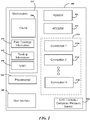
- FIG. 2 is a block diagram of some components in a node 200 as may occur in some embodiments.
- Power module 205 may be any suitable connection to a power source, e.g., a connection to a land-based power source (a grid-based alternating current), to a solar cell, to a battery source, to a voltage difference in a natural medium, etc.
- Network access module 210 may be a component in the node 200 used to provide local network access.
- network access module 210 may be a WIFI wireless access point, a wired Ethernet terminal, etc.
- Connection bay 215 may include a plurality of connection modules 215a-n for communication with peer nodes.
- Connection modules 215a-n need not be the same form of communication, e.g., they may be microwave, line-of-sight optical, laser-based, radiofrequency, directional antenna systems, hardline connections, etc.
- the connection modules 215a-n may have different bandwidths and communication rates.
- Connection modules 215a-n may include both transmission and reception components and may be associated with a same or different peer node. Some connection modules 215a-n may be specifically designed for communication with a backbone.
- Connection modules 215a-n may include individual or shared actuators for alignment and directional transmission/reception.
- Location module 220 may include one or more components used for determining location and/or orientation, such as a GPS reception system, a compass, an altimeter, a pressure sensor, etc.
- the pressure sensor may be used to acquire relative barometric measurements as compared with peer nodes as described further herein.
- Memory module 230 may include one or more memory devices, which may be solid-state memories, hard disk memories, etc.
- a cache 235 may be used for storing user-requested information as discussed in greater detail herein.
- Peer topology information 240 may include a record of peer locations, their ranking relative to a backbone node, etc., for example as determined during Association, as discussed herein.
- Routing information 245 may include protocols for sending information via different peers based upon channel conditions, traffic load, weather conditions, network load, etc.
- Logic 250 may include operational logic to maintain connection modules 215a-n, to forward and redirect information to users, to generally maintain the operation of node 200, etc.
- processors 255 may be used to run the logic 250. Though this example depicts a common memory-processor instruction architecture, one will readily recognize that the described operations may be implemented using other tools, e.g., Field-Programmable Gate Arrays (FPGAs).
- a user interface 260 may be included for an in-field operator or for users to interact with the node 200, e.g., to designate its mode of operation, to configure its position, to receive data, etc..
- connection modules 215a-n may include a backhaul subsystem module.
- the backhaul subsystem may be designed to carry a large data rate from node to node and may share a fraction of the capacity at each node with the access subsystem.
- the backhaul subsystem link to neighboring nodes may be designed to carry large amounts of data capable of supplying many access subsystems. This may facilitate the chaining of many such nodes together.
- the nodes are seldom repositioned following deployment. There may be some small movement of a node due to buildings settling and temperature variation but larger movements may occur when a node is to be physically moved to another site, e.g., for environmental reasons.
- the access module 210 may be designed to share connectivity with both mobile and fixed end user devices in the area immediately surrounding the node (and perhaps to users closer to this node than to other peer nodes).
- the access subsystem may use wide area coverage wireless technologies to connect with many end users in its vicinity. Rather than a physical fiber, the backhaul subsystem may utilize narrow beam communication systems (optical, RF with high gain antennas, etc.) to pass high data rates to neighboring nodes efficiently and to minimize communication interference between other backhaul nodes.
- the narrow beam technologies used for the backhaul subsystem may include (but are not limited to), RF, millimeter wave, and optical.
- Beam divergences for the backhaul subsystem may be approximately 3-5 degrees for RF systems, 1-3 degrees for millimeter wave systems, and 0.05 to 0.5 degrees for optical systems, though these ranges are offered as examples and one will readily recognize that others are possible.
- Building sway, building settling, temperature drift, etc. may affect the viability of these different ranges. Such changes induced on an aligned system may induce small changes of a fraction of a degree. In some embodiments, this motion may be handled with small field of view steering technologies or aligning the devices to the beam centers such that the movement is within the beam divergence angle.
- the backhaul subsystem may need to search over an angular range of 180 degrees in the X-Y plane and 30 degrees in the Z axis to locate a nearby node to connect to.
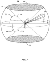
- FIG. 3 is three-dimensional depiction of the line-of-sight (LOS) angles and ranges relevant to a node 305 as may occur in some embodiments.
- a node 305 may be able to orient its LOS transmitter / receiver within an LOS region 335 having a range 345.
- the node 305 may be able to rotate a full 360° about a vertical access (i.e., yaw axis). This region may extend from a plane 345 about a horizontal axis (i.e., pitch axis) to a maximum angle 320a above the plane 340 and a maximum angle 320a below the plane 340.
- a horizontal axis i.e., pitch axis
- Regions 330a,b may accordingly be excluded from the node 305's visibility at boundaries 315a,b. These regions are not necessarily to scale and will change with various embodiments (e.g., the region 330a may be a null region and the zenith accessible to the node 305's visibility in some embodiments).
- a radius 345 may depend upon the hardware of the node 305 and the transmission channel conditions (e.g., humidity, interference from other sources, etc.).
- a window 325 may reflect the actual region seen by the node 305 (multiple such windows may be present for different devices) at a given position along the range 345. The window is here seen increasing in dimensions along the range as a consequence of the divergence factor.
- the node 305 may scan the window 325 across a region far from the peer node.
- LOS ranges depicted herein may be unrelated to the wireless access ranges, radiofrequency, and/or microwave communication methods of other modules.
- FIG. 4 is a flow diagram depicting a very high-level example deployment and operation of a node network as may occur in some embodiments.
- the node placement may be determined in a simulated environment.
- one or more planners may identify the best physical and logical topologies for the nodes in a given geographic and population context. Example aspects of this operation are discussed in greater detail herein, e.g., in the sections with heading "Node-Placement Planning".
- the nodes may be physically placed in the geographic region.
- a dedicated group of technicians may install the nodes, or the nodes may be established in an ad-hoc manner by members of the community. For example, nodes may be mailed to participating community members with instructions for their installation.
- the nodes may engage in Discovery and Alignment procedures to locate and orient towards their peers.
- the nodes may determine the relative physical location of their nearest peers and the orientations necessary to perform line-of-sight communication with one or more of those peers. Example aspects of this operation are discussed in greater detail herein, e.g., in the sections with heading "Discovery and Alignment”.
- the nodes may engage in Association to determine their topological relation relative a backbone.
- the nodes may determine which of their neighbors they should form LOS connections with so as to acquire access to a network backbone.
- the backbone may be a connection to the Internet or to a subnetwork. These formations may prevent node subgroups from being isolated from the backbone connection. Example aspects of this operation are discussed in greater detail herein, e.g., in the sections with heading "Association".
- the nodes may perform various steady-state operations, including, e.g., routing, network management, data caching, etc.
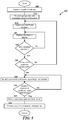
- FIG. 5 is a flow diagram depicting operations in a node-placement-planning algorithm as may occur in some embodiments.
- the system may receive various target constraints.
- the planners of the network may specify the maximum number of nodes available, the desired coverage per region, prioritization of certain communities or areas, the iteration parameters discussed in greater detail herein, etc.
- the particular, real-world information for a target region may be provided.
- This information may include the population distribution of the target region (averaged, or for different temporal periods), the obstacles (natural and man-made) in the region, the elevation of portions of the region, the location of a backbone connection, etc.
- the system may select the next backbone connection to be considered. For example, a plurality of connection points may be specified along the backbone at regular intervals. Each point may afford various benefits and/or drawbacks. For simplicity of explanation, consideration of a single backbone connection at a time is discussed here, but one will readily recognize that the discussed methods may be extended to approaches in some embodiments where multiple backbone connections are considered simultaneously.
- the system may perform an iteration among the leaves of the presently considered backbone. Initially, there may be only a single leaf (the backbone connections), but proposed peers will be generated during this step based on various of the provided parameters. These proposed peers may themselves serve as leaves during a subsequent iteration to generate additional peers/leaves.
- the system may determine if a stop condition has been reached. For example, where each of the contemplated paths has exhausted the maximum available number of nodes, the system may conclude the generation process. Similarly, if a desired level of coverage were specified and a path provides this coverage, leaves may no longer be generated for the path. One will recognize that the system may continue generating leaves for those nodes associated with paths that have not yet met a stop condition, even though other paths may have met the condition. In some embodiments, local minima may be avoided by ignoring a stop condition, but making a record of it having been met for a given path (this may generate a new path in itself, e.g., a subpath of the larger path). For example, this may prevent a path that satisfies a lower prioritized stop condition (e.g., preferred cost) from preventing the generation of path satisfying a higher prioritized stop condition (e.g., desired coverage achieved).
- a lower prioritized stop condition e.g., preferred cost
- the system may determine if all the backbone positions have been considered. If not, the system may generate a new series of nodes and paths for the next backbone connection. These may be separately considered from those generated in the previous backbone node iteration, or the synergies between the paths may be considered below at block 535.
- the system may identify and record paths based upon the target constraints. For example, whereas the constraints may have previously dictated that no further leaves be generated, the constraints are here used to "prune" the possible connections to identify those paths associated with the highest metric values. For example, for a tree with a branching factor of 3, wherein 5 iterations were performed, there may be as many as 364 nodes (1+3+9+27+81+243) to consider (this is merely an example and many more than 5 iterations may be performed, and a different branching factor than 3 may be used, in some embodiments). Of these 364 nodes, 243 nodes may be leaves (the remaining nodes being intermediate nodes to the backbone).
- each of these 243 leaves there may be one or more possible paths (based upon the LOS limitations for neighboring nodes) to the backbone. There may also be many subpaths from the intermediate nodes to the backbone. Metric determinations based on the constraints (e.g., cost, coverage achieved, difficulty of installation, etc.) may be determined for each of these paths.
- the system may determine if the desired number of paths has been determined. If not, additional paths and their corresponding metrics may be determined. Once the desired number of paths has been identified, at block 545, the system and/or human planner may select one or more paths associated with preferred metric values. The planner may adjust the node positions manually at block 550 to generate the final node topology for in-situ installation.
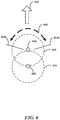
- FIG. 6 is a top-down, two-dimensional depiction of the line-of-sight angles and ranges relevant to a node during the path planning algorithm as may occur in some embodiments. Although a data structure reflecting these variables may appear in the planning system, the two-dimensional representation of FIG. 6 is merely to facilitate explanation, and one will readily recognize that the system anticipates the three-dimensional structure of FIG. 3 when assessing peer-to-peer interactions.
- the system may consider a previously-placed node 605 and its child node 610, which is presently a leaf considered in this iteration.
- the LOS ranges of the nodes are depicted by range circles 615 and 620, although as discussed previously, the system may consider the three-dimensional character of the ranges and limitations imposed by terrain, hardware, etc.
- Child node 610 was previously placed at the periphery of node 605's LOS range.
- the system may consider a priority direction 640 and span 630 with limits 625a and 625b.
- the span need not be along a circle, but may be a line path along the periphery of whatever form child node 610' s visibility assumes.
- Candidate child nodes may be placed along this span 630 in accordance with a desired branching factor.
- Priority direction 640 may determine the width of span 630 (e.g., based on the distance to a weighted centroid, the variance about the weighted centroid, local topology around the priority direction, etc.) and the limits 625a and 625b and be generated based upon one or more constraints.
- the system may identify centroids in the population density, weight the centroids by priority and then determine the priority direction 640 based upon the relationship between the position of child node 640 and the weighted average (in this example, the weighted average would be in the direction of the top of the page).
- FIG. 7 is an example iteration of a node-placement-process as may occur in some embodiments.
- Population density data may have indicated that community members frequent regions 705a-e. Some of these regions 705b-e, e.g., an office complex or downtown center, may be grouped closely together. Other regions 705a may be isolated, e.g., depicting isolated villages, service stations, etc. Elevation data may indicate that a large mountain 710 is present in the region.
- the system may seek to identify an optimal node placement providing network access to the various regions, beginning from a backbone 730.
- a connection point 725 may serve as an initial node in the contemplated network.
- a first node 715a has been placed within optical range of the connection point 725.
- the system has identified the priority direction 740, e.g., based upon a desire to service the community reflected by regions 705b-e.
- the system may also iterate across different constraint profiles to consider different priority directions 740 (though, for simplicity, only one direction is considered here - considering multiple priority directions at each iteration may generate many more than the 364 nodes presented in the example above).
- FIG. 8 is an example iteration of the node-placement-process of FIG. 7 .
- the system has placed three new leaf nodes 815a-c.
- each of these leaf nodes 815a-c offer different advantages / disadvantages.
- Node 815a may ultimately provide access to region 705a at lower cost than the other options.
- Node 815b may provide the most direct path the regions 705b-e.
- Node 815c may avoid certain limitations of elevation, but moves farther from the populated regions.
- FIG. 9 is an example iteration of the node-placement-process of FIG. 7 depicting effects of a holistic directional growth criterion as may occur in some embodiments.
- leaves have been generated for each of node 815a-c in accordance with the constraints and consequent priority directions 930a-c.
- the priority directions 930a-c need not be the same (though they are in this example) and may vary in a "greedy manner" depending upon how the constraints interpret the current node's situation.
- the new leaf nodes 915a-c, 920a-c, 925a-c have been generated pursuant to a "holistic" priority to reach the largest serviceable population, i.e., regions 705b-e.
- FIG. 10 is an example iteration of the node-placement-process of FIG. 7 depicting effects of a greedy directional growth criterion as may occur in some embodiments.
- the priority directions 1030a-c have been reevaluated locally for each node 815a-c.
- node 815a 's potential to reach region 705a has predominated the other constraints/priorities and the priority direction 1030a adjusted accordingly.
- node 815b 's potential to reach regions 705b-e and/or its ability to reach a higher elevation (and possibly children with greater LOS range) has predominated the other constraints/priorities. Accordingly, priority direction 1030b has been adjusted.
- the rules governing creation of the priority direction may consider the presence of other nodes and priority directions.
- priority direction 1030c may be generated because the region to the bottom right remains unexplored by the other paths. Weights corresponding to different priorities may be adjusted such that the priority directions and consequent leaves generated with each iteration provide a desirable diversity of path options for consideration.
- FIG. 11 is an example resultant path of the node-placement-process of FIG. 7 as may occur in some embodiments. Node placement may continue until a stop condition is reached as discussed herein. The system may then identify all the viable paths among the placed nodes and then assign them appropriate metrics. For example, FIG. 11 depicts a path from the backbone via nodes 1130a-j to regions 705b-e. This path may receive a relatively lower-valued metric as it requires a considerable number of nodes and fails to service the region 705a.
- FIG. 12 is an example resultant path of the node-placement-process of FIG. 7 as may occur in some embodiments.
- This example path may receive a higher relative metric value than the example of FIG. 11 as the nodes 1230a-h service all the regions 705a-e. However, this path still requires a rather large number of nodes.
- FIG. 13 is an example resultant path of the node-placement-process of FIG. 7 as may occur in some embodiments.
- This example demonstrates that pruning may not only remove nodes outside the considered path, but may remove nodes within a considered path, if they are deemed irrelevant.
- the system has discovered that placement of a node 1330a atop the mountain 710 permits it extend its LOS range considerably.
- strategically placed periphery nodes 1330b and 1330c permit the network to service each of regions 705a-e with many fewer nodes than the examples of FIGs. 11 and 12 .
- the planning system may determine that the LOS region about a node is a "blob", rather than a portion of a geometric solid (such as a hemisphere) as a consequence of the local terrain. Absent terrain or weather considerations, however, the LOS region may resemble a hemisphere (or even as a sphere missing some region in its lower hemisphere, e.g., as may be the case for node 1330a atop the mountain 710 ). In the example of FIG. 13 , however, the mountain would subtract a portion of the hemisphere LOS region about node 715a.
- the planning system may initially assume the maximum possible dimensions of LOS region 335, and then "carve out” local obstructions, or reduce the range 345 based on aggregate conditions (e.g., regions with consistently high humidity).
- the span 630 may be represented as a line path along the considered node's LOS region's intersection with the ground plane, rather than as an angle.
- the line path may be selected such that its center point coincides with a line extending from the considered node outward in the priority direction.
- candidate nodes may be placed based upon, e.g.: the population centroids; environmental factors; permissions of land owners; power availability (solar, grid connections, etc.); access strength of neighbor nodes. Metric evaluations may consider similar, or the same, factors.
- FIG. 14 is an example result of a coverage-driven growth criterion on a node-placement-process as may occur in some embodiments.
- the planner may specify that "coverage" is to take priority over other factors when selecting priority directions. Accordingly, the system may generate node placements and select paths that provide maximum coverage as depicted in FIG. 14 .
- FIG. 15 is a flow diagram depicting a leaf generation process for a coverage-driven growth criterion in a node-placement-process as may occur in some embodiments.
- the system may determine the centroids of the uncovered regions (e.g., regions not yet being serviced). For example, the regions may be construed as a Voronoi diagram, the centroids as the centers of the respective Voronoi region (generated, e.g., following a K-means clustering).
- the system may identify the direction to the closest and/or largest centroid for a particular leaf node under consideration.
- the system may determine the number of leaves to generate (e.g., the branching factor may vary depending upon the priority).
- the system may determine the leaf spread and at block 1525 the system may generate the new leaves.
- FIG. 16 is an example result of a demand-driven growth criterion on a node-placement-process as may occur in some embodiments.
- the planner may specify that "demand" is to take priority over other factors when selecting priority directions. Accordingly, the system may generate node placements and select paths that service the maximum number of individuals.
- FIG. 17 is a flow diagram depicting a leaf generation process for a demand-driven growth criterion in a node-placement-process as may occur in some embodiments.
- the system may determine the distance to population centroids. For example, the populations may again be grouped based upon, e.g., a K-means or similar grouping method.
- the system may identify the direction to the nearest / largest population centroid for a leaf node under consideration.
- the system may determine the number of leaves to generate (e.g., the branching factor may vary depending upon the priority).
- the system may determine the leaf spread and at block 1725 the system may generate the new leaves.
- the nodes may be physically placed in the region at their determined positions. Following placement, the nodes may then locate their peers and form appropriate connections to achieve the desired level of service identified in the planning stage.
- the identification of neighboring peers is generally referred to as “Discovery” herein, the orientation to a peer as “Alignment”, and the formation (via the first or subsequent orientations) of appropriate connections as determined during planning as “Association”.
- Discovery the orientation to a peer
- Association the formation (via the first or subsequent orientations) of appropriate connections as determined during planning as "Association”.
- Cartesian layout e.g., a "Star” network as discussed herein.
- Different layouts may be generated as a result of the planning phase discussed above.
- FIG. 18 is topological block diagram of node relations in a deployed Cartesian mesh following Discovery, Alignment, and Association, as may occur in some embodiments.
- Each of the columns may have been generated from a planning analysis beginning at a respective backbone connection.
- the column comprising nodes 1815a-c may result from planning iterations beginning at backbone connections 1805b.
- FIG. 19 is topological block diagram of node relations in a deployed Cartesian mesh prior to Discovery/Alignment as may occur in some embodiments. While FIG. 18 generally refers to the logical relation between nodes (i.e., their routing connections between one another) rather than their geographic location, FIG. 19 depicts ranges 1910a and 1910b reflecting the LOS for nodes 1815b and 1825b. During “Discovery", the node 1815b should recognize that the peer 1815a is within LOS range based upon their respective locations. Similarly, the node 1825b may recognize that each of peer nodes 1820a and 1825a are within LOS range.
- node 1825b may form a default connection with either (or in some embodiments, both) of nodes 1820a and 1825a. These default connections may be refined (e.g., supplemented or removed) subsequently during Association so as to achieve a desired connection with a backbone node.
- the nodes may determine their location information actively, e.g., by querying a GPS system or receiving coordinates from a technician on-site.
- the installing technician may take an image of the node following installation, including one or two landmarks in the image. These landmarks may then be cross-referenced with database images to infer the location of the node.
- each node may also rely (in lieu of, in addition to, or in complementation with the other techniques) on the passive transfer of information by users between its peers.
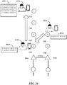
- FIG. 20 is topological block diagram depicting passive user-based information propagation during Discovery in a deployed Cartesian mesh as may occur in some embodiments.
- a user with a mobile device may move from position 2010a to position 2010b and then to position 2010c.
- each of the nodes A-F may have local network access activated (e.g., WIFI) even though they are not yet in communication with a backbone connection. Accordingly as the user passes between the different nodes the user's mobile communication device may associate with each of the nodes.
- WIFI local network access activated
- the user may first pass node B which recognizes its GPS position as being "32.22.21
- the mobile communication device may be running an application or otherwise be able to store this information locally in its memory in a location log 2015a.
- the mobile device may associate (e.g., form an 802.11 association) with Node C.
- the GPS positions values in this example are provided merely to facilitate understanding and do not reflect values that might actually be used in real-world implementations of embodiments.
- Node C may pull the position log 2015a from the mobile device, make its own internal record of the position of Node B, and supplement the user's mobile device location log 2015b with its own location information, as well as any location not already present that it previously acquired. For example, had Node C previously encountered a user who had passed Node A, the location information for Node A would be included in the location log 2015b. By the time the user has reached position 2010c, the user has received and provided location information from and to each of Nodes D, E, and F.
- the user/subscribers may initially be given membership (802.11 authentication, etc.) to all of the node access points. For example, in a WIFI system this may be accomplished by providing a common SSID/password or by providing open access.
- the access point subsystem sends a message to the user.
- the message may, e.g., contain the following information: the MAC address of the node (or other unique identifier); GPS coordinates of the node; Altimeter data from the node; the hardware types of the various node communication systems; and association information for the node (e.g., whether it is in communication with a backbone node as preferred by the planning process).
- the user device may store this information and subsequently convey it to a future encountered node.
- each node may have a complete list of all neighboring nodes.
- the node may perform a random search with narrow beams, e.g., a small window 325.
- the node may use a step size of one half the beam width (e.g., width of the window 325 ) and a dwell-time at least twice the time to step between two angles.
- a beam steering system could take 5ms to switch between two positions and dwell for 10ms at each position.
- an angular step size of 2 degrees may be used.
- both narrow beams may need to align which would take 1.82 million steps.
- a millimeter wave system with a 2 degree beam width and a step size of 1 degree may instead allow each node would search through 5400 steps. Detection would take 29.1 million steps, which would take 121 hours.
- an optical system with a beam width of 0.2 degrees with a 0.1 degree step size would require each node to search through 540,000 steps. This alignment may take 291 billion steps and 138 years.
- the narrow beam random search approach is therefore generally considered herein for embodiments having wider beam widths.
- Some embodiments employ random searches with wider beams (e.g., larger window 325 ). For example, some node embodiments use a separate signal with a wider beam for Alignment, but then use a narrower beam with higher speed data during normal operation. This wider beam signal could be used to narrow the search area for the narrow beam to its beam width.
- an omnidirectional receive antenna/sensor or omnidirectional transmit antenna/source may be connected to the node. This omnidirectional device may reduce the number of search steps of each node to the square root of the set time as it would not require that each node have exactly determined its relative alignment with its peer for the two to recognize one another.
- Some embodiments implement a GPS-assisted search that may employ additional long-range wide area wireless technology.
- Each node may be fitted with an altimeter (e.g., using the barometric approach described herein) and GPS receiver to determine its position in space.
- the nodes may then share this information with neighboring peers to aid in alignment.
- An additional omnidirectional radio may also be used to share the information.
- the frequency and transmit power of this radio may be chosen to allow the signal to adequately reach the nearby nodes (e.g., as determined during the planning phase described above). Collision avoidance techniques may be performed and could be used to share the channel between the many nodes.
- the GPS data may allow the node to confine the search region to the error band of its position data and the error band of the peer node's position data.
- This error may range from a worst case of 8 degrees in the horizontal plane at extremely close range (80 meters) and 1 degree in the Z axis to a worst case of 0.6 degrees in the horizontal at 10km and 0.006 degrees in the Z axis. This may allow for a much faster search process during Alignment.
- Some embodiments employ a GPS-assisted search using an access subsystem. These approaches may remove the need for an extra communication system solely for the purpose of alignment.
- the access subsystem wireless range may allow the nodes to communicate directly with each other and to relay their address and coordinate information. As this information payload may be transmitted at a low data rate, it may be possible to use a lower bit rate (fewer bits/Hz) to pass the message.
- the access technology's range may render the GPS-assisted search using an access subsystem approach unfeasible in some situations.
- the limited range may prevent the passage of address and coordinate information to the neighboring nodes.
- the passive transfer of peer information by users travelling between nodes as described herein may be used instead.
- the nodes may be able to infer their location exclusively from GPS information, information provided by an installing technician, etc. However, in some embodiments, position information may be inferred from a plurality of sources. In some embodiments, relative pressure information may be used by the nodes to complement GPS information so as to achieve more accurate determinations of the nodes' relative orientations.
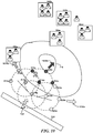
- FIG. 21 is a cross-sectional perspective view of an incline 2110a upon which nodes 2115a-c are placed and relative barometric readings are taken as may occur in some embodiments.
- the location logs, or other information transferred passively between the nodes, may include a barometric reading for a node.
- the nodes may compare the difference between their own barometric reading and the reading of a peer to infer the difference in elevation (and corresponding angle in which to scan the window).
- the node 2115a is at a slightly lower elevation relative to node 2115b. Accordingly, the pressure at node 2115a is higher than at node 2115b and a small, positive (+10) difference is noted.
- node 2115c is located at a much higher elevation than node 2115b. Accordingly, the pressure at node 2115c is lower than at node 2115b and a large, negative (-75) difference is noted.
- the pressure to angle correspondence may be inferred from a table or determined dynamically.
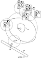
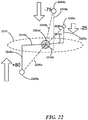
- FIG. 22 is a three-dimensional perspective view of several nodes 2205a-d and their barometric readings relative to a first node as may occur in some embodiments.
- each node may be able to infer a topological mapping of its local surroundings.
- the node 2205d may recognize, based e.g., on GPS coordinates, that within the terrestrial plane 2215 (i.e., a plane perpendicular to a line passing from the node to the center of the Earth) it is a distance 2210a from the node 2205a, a distance 2210b from the node 2205b, and a distance 2210c from the node 2205c.
- node 2205d may infer relative vertical heights 2225a-c for each of nodes 2205a-c. With the heights 2225a-c and distances 2210a-c known, the node 2205d may readily infer the Euclidean distance 2220a-c to each node and the corresponding angle relative to the terrestrial plane 2215.
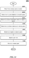
- FIG. 23 is a flow diagram depicting a process for orienting peer-nodes during Alignment based upon their peers' barometric data as may occur in some embodiments.
- the node may determine the peer nodes nearest in the terrestrial plane.
- the node may determine the in-plane distance to the peer.
- the node may determine the relative barometric deltas do the nearest peers and the corresponding height values.
- the node may determine the Euclidean distance to the nearest peers.
- the node may determine the angle to the nearest peers.
- the node may update its locally stored information regarding the nearest peers to reflect their relative positioning.
- the node may orient to the nearest peer, e.g., as part of a default connection prior to Association.
- each node has only enough communication links to reach some of its neighboring nodes, it may be very desirable for the system to choose the correct adjacent node to link to in accordance with the Planning phase. If the system additionally has communication links with different speeds, it may be especially preferred that the correct pairs of links (e.g., as specified in the Planning process) are established.
- the Association phase includes one or more processes for ensuring that appropriate links are formed.
- the transition from the Alignment process to Association may occur based on one or more conditions, or may occur organically node-by-node as each acquires sufficient information regarding their peers.
- each node may transition from the Alignment procedure to the Association procedure after a fixed period of time, after a sufficient amount of peer location information has been acquired, or upon some other signal.
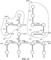
- FIG. 24 is topological block diagram depicting isolated formations following Alignment and prior to Association as may occur in a deployed Cartesian mesh in some embodiments. Isolated "island" networks 2405a,b have formed lacking a backbone connection, let alone the appropriate backbone connection determined during Planning. In this example, only node 2410a has properly associated with backbone connection 2415a as intended during Planning. While node 2410b may recognize both nodes 2410c and 2410a as being within LOS range, node 2410b may have formed a default association with node 2410c.
- node 2410d failing to associate with node 2415a
- node 2410e failing to associated with node 2410f
- 2410f with backbone 2415c.
- the nodes within isolated networks 2405a,b may recognize that they lack a connection with a backbone 2415b.
- Each node may share path information with its peers until a path to the backbone connection has been identified.
- FIG. 25 is topological block diagram depicting an end ranking following Association as may occur in a deployed Cartesian mesh in some embodiments.
- each node is given a two part topological reference, referred to herein as a rank: (X,Y).
- the first part of the rank (X, the backbone component) represents the node's relation to the backbone (e.g., to a high speed network devices).
- the second part of the rank (Y, the subnetwork component) represents the node's relation to other nodes in the subnetwork (e.g., to the regular speed network devices).
- the relation may be, e.g., a number of hops from a backbone node associated with the subnetwork.
- nodes 2505a-d may have had rank 0,0. As they began communication with one another, they would select unique backbone rank identifiers as indicated. Nodes unconnected to the backbone may begin with an arbitrary, non-zero X rank (e.g., 9999).
- a node 2505a with a hardcoded (0,0) rank may look through its list of neighboring node coordinates and determine which nodes are closest and have a rank of (X,0) where the X is any value (the nodes 2505b-d will assume other X ranks as knowledge of the node 2505a propagates).
- the node 2505a may retain this (0,0) ranking based on a hard-coded preference specified in the planning phase (e.g., a literal hardcoding by the installing technician, a rule established in the logic code, etc.). This node may then begin a search with its high speed optical heads (or whatever other communications module is available to the embodiment) in the direction of the neighboring nodes.
- the other devices will begin to search in the direction of the (0,0) node using the GPS coordinates of the (0,0) node.
- a node finds the (0,0) node it may review the ranking information to determine if it falls within the subnetwork of the 0,0 node. If so, the node 2510a may update its rank to (1,0).
- the distance between nodes may govern the priority of assignment, resulting in there being eventually only one (1,0) ranked node 2505b on the backbone connected to the (0,0) node 2505a.
- This rank is updated in the broadcast message passed on to the neighboring nodes.
- Each other node with rank (X,0) then starts a search looking for node (1,0) until a link is made and the new node 2505c is given the rank (2,0) and so on.
- the regular speed node links closest to node 2505a may seek out the node with the (0,Y) where Y is any number (the preference for X being zero again based on a total ordering associated with distance).
- Each node which has been informed of a nearby node with a (0,Y) rank may begin a search of the coordinate area around the GPS coordinates of the node.
- the (0,Y) node may begin a search in the direction of the closest (X,Y) nodes.
- the node 2510a-d updates its rank to (1,Y) and this rank is updated in the message shared with neighboring nodes.
- Other nodes without associated hardware that receive the message with a device with a (1,Y) node begin a search in the direction of the (1,Y) node and the process continues from there.
- the node Association process may proceed generally as follows: 1) From an initial start state (e.g., following installation or reset), every node selects a random rank between 1 and N where N is the number of nodes in the network, excluding node 0.
- Node 0 selects rank 0; 2) Each time a node receives a location list update (e.g., from a passing person, or from a neighbor node) it looks through the list to identify the location of the first known node with a higher rank and the first known node with a lower rank as given by the list; and 3) The node then attempts to connect first to the lower rank node (i.e. closer to node 0).
- a location list update e.g., from a passing person, or from a neighbor node
- the node updates its rank to the rank of the node it connected to + 1. It then attempts to connect to the higher ranked node. If the connection to the higher ranked node succeeds the node it connected to updates its rank to the connecting node's rank + 1.
- a node (arbitrarily referred to as "Node Z") with Y rank 5 receives a list that identifies the location of nodes with Y ranks 0,2,8,10. Node Z first attempts to connect to the node with Y rank 2. If the connection is successful Node Z's Y rank is updated to rank 3. Node Z may attempt to connect to the node Y ranked 8 and if successful, the node Y ranked 8 updates its Y rank to 6 instead.
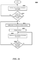
- FIG. 26 is a flow diagram depicting a local process for updating a node ranking as may occur in some embodiments.
- the node may actively solicit ranking information from its peers.
- the node may determine if the acquired ranking information includes a backbone node.
- the node may notify its peers of the decision to adjust its ranking.
- the node may adjust its ranking. Subsequent requests for its ranking information will now include this new ranking.
- the node may passively solicit ranking information from its peers.
- ranking information may back-propagate to the connection nodes on the backbone.
- the backbone nodes have knowledge of the desired network topology and may resubmit the ranking information into the network so as to accord with the preferred ranking. Accordingly, at block 2630 the node may determine if a higher prioritized path has been identified, e.g., as designated by a backbone node. If so, the ranking may be adjusted pursuant to blocks 2615 and 2620. If no higher priority information has been received, then the node may continue to passively listen for incoming ranking information.
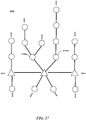
- FIG. 27 is a topological block diagram depicting a Star-network 2700 following Association as may occur in some embodiments.
- the planning phase may have imposed ranking conditions such that nodes 2710a,b either facilitate branching, or do not facilitate branching from the backbone node.
- branching may be suitable at points of high elevation (buildings, mountains, etc.) and for nodes having many different communication components (e.g., more optical components and more memory).
- FIG. 28 is a topological block diagram depicting a caching topology in a Cartesian-network as may occur in some embodiments.
- locations may be strategically determined where heavy usage or traffic may occur.
- caching (or additional caching) memory may be provided to improve the network's efficiency during operation.
- FIG. 29 is a topological block diagram depicting a rerouting event in a Cartesian-network as may occur in some embodiments.
- fog 2905 may form between the nodes 2910a and 2910b.
- the anticipated weather patterns may be taken into consideration and alternative routing preferences included in the distributed nodes.
- node 2910a may be redirected to form an optical connection with node 2910c.
- this rerouting may be performed dynamically, e.g., by restarting the Association process for the nodes disconnected from the backbone.
- this Association process may differ from the original Association and may consider rerouting guidance provided from the planning phase.
- Routing adjustments may not only include the creation of new connections, but may instead include communication module changes.
- fog 2905 may be impenetrable at optical wavelengths, but not a microwave wavelengths. Accordingly, nodes 2910a and 2910b may switch to another communication medium (e.g., microwave) until the condition abates.
- another communication medium e.g., microwave
- FIG. 30 is a block diagram of a computer system as may be used to implement features of some of the embodiments (e.g., as may be used to perform the Planning process or as may appear in the node 200).
- the computing system 3000 may include one or more central processing units ("processors") 3005, memory 3010, input/output devices 3025 (e.g., keyboard and pointing devices, display devices), storage devices 3020 (e.g., disk drives), and network adapters 3030 (e.g., network interfaces) that are connected to an interconnect 3015.
- the interconnect 3015 is illustrated as an abstraction that represents any one or more separate physical buses, point to point connections, or both connected by appropriate bridges, adapters, or controllers.
- the interconnect 3015 may include, for example, a system bus, a Peripheral Component Interconnect (PCI) bus or PCI-Express bus, a Hyper-Transport or industry standard architecture (ISA) bus, a small computer system interface (SCSI) bus, a universal serial bus (USB), IIC (I2C) bus, or an Institute of Electrical and Electronics Engineers (IEEE) standard 1394 bus, also called "Firewire”.
- PCI Peripheral Component Interconnect
- ISA industry standard architecture
- SCSI small computer system interface
- USB universal serial bus
- I2C IIC
- IEEE Institute of Electrical and Electronics Engineers
- the memory 3010 and storage devices 3020 are computer-readable storage media that may store instructions that implement at least portions of the various embodiments.
- the data structures and message structures may be stored or transmitted via a data transmission medium, e.g., a signal on a communications link.
- a data transmission medium e.g., a signal on a communications link.
- Various communications links may be used, e.g., the Internet, a local area network, a wide area network, or a point-to-point dial-up connection.
- computer readable media can include computer-readable storage media (e.g., "non transitory" media) and computer-readable transmission media.
- the instructions stored in memory 3010 can be implemented as software and/or firmware to program the processor(s) 3005 to carry out actions described above.
- such software or firmware may be initially provided to the processing system 3000 by downloading it from a remote system through the computing system 3000 (e.g., via network adapter 3030).
- programmable circuitry e.g., one or more microprocessors
- special-purpose hardwired circuitry may be in the form of, for example, one or more ASICs, PLDs, FPGAs, etc.
Landscapes
- Engineering & Computer Science (AREA)
- Computer Networks & Wireless Communication (AREA)
- Signal Processing (AREA)
- Mobile Radio Communication Systems (AREA)
Claims (10)
- Computerimplementiertes Verfahren zur Verwendung in einem ersten Knoten zum Herstellen einer Verbindung mit einem Hauptnetz (125) in einem Netzwerk (100) mit einer Vielzahl von Knoten, wobei jedem Knoten eine zweiteilige topologische Referenz gegeben wird, die eine Ranginformation darstellt, wobei das Verfahren umfasst:Bestimmen von Standardwerten für die zweiteilige topologische Reference des ersten Knotens, wobei die zweiteilige topologische Referenz umfasst:einen ersten Referenzteil, der eine topologische Beziehung des ersten Knotens relativ zu dem Hauptnetz (125) wiedergibt; undeinen zweiten Referenzteil, der eine topologische Beziehung des ersten Knotens relativ zu einem oder mehreren Knoten in einem ersten Teilnetzwerk des Netzwerks (100) wiedergibt, wobei das erste Teilnetzwerk den ersten Knoten umfasst;Empfangen einer zweiteiligen topologischen Peer-Referenz von einem Peer-Knoten, wobei die zweiteilige topologische Peer-Referenz umfasst:einen ersten Peer-Referenzteil, der eine topologische Beziehung des Peer-Knotens relativ zu dem Hauptnetz (215) wiedergibt; undeinen zweiten Peer-Referenzteil, der eine topologische Beziehung des Peer-Knotens zu einem oder mehreren Knoten in einem zweiten Teilnetzwerk des Netzwerks wiedergibt, wobei das zweite Teilnetzwerk den Peer-Knoten umfasst;Bestimmen, basierend auf der empfangenen zweiteiligen topologischen Peer-Referenz, dass der erste Knoten über Sichtlinien-Kommunikation, LOS-Kommunikation, mit dem Peer-Knoten zu verbinden ist; undZuordnen des ersten Knotens zu dem Peer-Knoten durch:Zuweisen eines ersten Werts zu dem ersten Referenzteil des ersten Knotens, wobei der erste Wert derselbe Wert wie der erste Peer-Referenzteil ist; undZuweisen eines zweiten Werts zu dem zweiten Referenzteil des ersten Knotens, wobei der zweite Wert aus einer auf den zweiten Peer-Referenzteil angewendeten Rechenoperation derart erzeugt wird, dass der zweite Wert eine Ordnung des ersten Knotens innerhalb des zweiten Teilnetzwerks angibt.
- Computerimplementiertes Verfahren nach Anspruch 1, wobei das erste Teilnetzwerk und das zweite Teilnetzwerk dasselbe Teilnetzwerk sind.
- Computerimplementiertes Verfahren nach Anspruch 1 oder 2, wobei der Peer-Knoten mit einem Hauptnetz-Knoten in Kommunikation steht, bevor der erste Knoten die Ranginformation empfängt.
- Computerimplementiertes Verfahren nach einem der Ansprüche 1 bis 3, wobei die zweiteilige topologische Referenz eine Ranginformation darstellt, die aus einer Planungsphase ermittelte Zuordnungs-Metadaten umfasst.
- Computerimplementiertes Verfahren nach einem der Ansprüche 1 bis 4, wobei die zweiteilige topologische Referenz eine Ranginformation darstellt, die eine Prioritätsangabe umfasst, wobei die Prioritätsangabe angibt, dass die Ranginformation eine höhere Priorität hat als die zuvor durch den ersten Knoten empfangene Ranginformation.
- Computerimplementiertes Verfahren nach einem der Ansprüche 1 bis 5, wobei die zweiteilige topologische Referenz eine Ranginformation darstellt, die eine Gesamtordnung von Knoten innerhalb eines entsprechenden Teilnetzwerks angibt.
- Computerimplementiertes Verfahren nach einem der Ansprüche 1 bis 6, wobei die zweiteilige topologische Referenz eine Ranginformation darstellt, die eine Gesamtordnung von direkt mit dem Hauptnetz verbundenen Knoten aufzeigt.
- Computerimplementiertes Verfahren nach einem der Ansprüche 1 bis 7, wobei das Empfangen der zweiteiligen topologischen Peer-Referenz das aktive Abfragen des Peer-Knotens nach zweiteiliger topologischer Peer-Referenzinformation umfasst, wobei das Verfahren ferner umfasst:
passives Abfragen des Peer-Knotens nach zweiteiliger topologischer Peer-Referenzinformation, nachdem der erste Wert dem ersten Referenzteil des ersten Knotens zugewiesen wurde. - Computerlesbares Speichermedium, das Anweisungen speichert, die dazu konfiguriert sind, zu bewirken, dass ein Computersystem ein Verfahren nach einem der Ansprüche 1 bis 8 ausführt.
- Computersystem (3000), umfassend:mindestens einen Prozessor (3005);mindestens einen Speicher (3010), der Anweisungen umfasst, die konfiguriert sind, um zu bewirken, dass der mindestens eine Prozessor ein Verfahren nach einem der Ansprüche 1 bis 8 ausführt.
Priority Applications (1)
| Application Number | Priority Date | Filing Date | Title |
|---|---|---|---|
| EP18188703.5A EP3419218A1 (de) | 2014-11-06 | 2015-11-06 | Verbindung in sichtlinienkommunikationsnetzwerken |
Applications Claiming Priority (2)
| Application Number | Priority Date | Filing Date | Title |
|---|---|---|---|
| US14/534,709 US9661552B2 (en) | 2014-11-06 | 2014-11-06 | Association in line-of-sight communication networks |
| PCT/US2015/058869 WO2016073508A1 (en) | 2014-11-06 | 2015-11-03 | Association in line-of-sight communication networks |
Related Child Applications (1)
| Application Number | Title | Priority Date | Filing Date |
|---|---|---|---|
| EP18188703.5A Division EP3419218A1 (de) | 2014-11-06 | 2015-11-06 | Verbindung in sichtlinienkommunikationsnetzwerken |
Publications (2)
| Publication Number | Publication Date |
|---|---|
| EP3018862A1 EP3018862A1 (de) | 2016-05-11 |
| EP3018862B1 true EP3018862B1 (de) | 2018-08-15 |
Family
ID=54539857
Family Applications (2)
| Application Number | Title | Priority Date | Filing Date |
|---|---|---|---|
| EP18188703.5A Withdrawn EP3419218A1 (de) | 2014-11-06 | 2015-11-06 | Verbindung in sichtlinienkommunikationsnetzwerken |
| EP15193353.8A Not-in-force EP3018862B1 (de) | 2014-11-06 | 2015-11-06 | Verbindung in sichtlinien-kommunikationsnetzen |
Family Applications Before (1)
| Application Number | Title | Priority Date | Filing Date |
|---|---|---|---|
| EP18188703.5A Withdrawn EP3419218A1 (de) | 2014-11-06 | 2015-11-06 | Verbindung in sichtlinienkommunikationsnetzwerken |
Country Status (1)
| Country | Link |
|---|---|
| EP (2) | EP3419218A1 (de) |
Family Cites Families (3)
| Publication number | Priority date | Publication date | Assignee | Title |
|---|---|---|---|---|
| US7760665B2 (en) * | 2008-02-29 | 2010-07-20 | Cellnet Technology, Inc. | Selective node tracking |
| US8194600B2 (en) * | 2008-11-24 | 2012-06-05 | Qualcomm Incorporated | Air interface selection between nodes in peer-to-peer/ad-hoc networks |
| US8270313B2 (en) * | 2009-11-13 | 2012-09-18 | Mitsubishi Electric Research Laboratories, Inc. | Ranking nodes in networks with topologies arranged as directed acyclic graphs |
-
2015
- 2015-11-06 EP EP18188703.5A patent/EP3419218A1/de not_active Withdrawn
- 2015-11-06 EP EP15193353.8A patent/EP3018862B1/de not_active Not-in-force
Non-Patent Citations (1)
| Title |
|---|
| None * |
Also Published As
| Publication number | Publication date |
|---|---|
| EP3419218A1 (de) | 2018-12-26 |
| EP3018862A1 (de) | 2016-05-11 |
Similar Documents
| Publication | Publication Date | Title |
|---|---|---|
| US11398863B2 (en) | Alignment in line-of-sight communication networks | |
| US11652550B2 (en) | Deploying line-of-sight communication networks | |
| CA2966329C (en) | Association in line-of-sight communication networks | |
| Hsu et al. | Reinforcement learning-based collision avoidance and optimal trajectory planning in UAV communication networks | |
| Huang et al. | Deployment of heterogeneous UAV base stations for optimal quality of coverage | |
| Rolly et al. | Unmanned aerial vehicles: Applications, techniques, and challenges as aerial base stations | |
| He et al. | Towards 3D deployment of UAV base stations in uneven terrain | |
| CN113169792B (zh) | 在具有仅接收器mmWave 5G BS天线的网络和其他网络中的UAV通信的方案 | |
| Cho et al. | Performance comparison of heuristic algorithms for UAV deployment with low power consumption | |
| US11535275B2 (en) | Digital map truth maintenance | |
| Esrafilian et al. | Simultaneous user association and placement in multi-UAV enabled wireless networks | |
| Chen et al. | A deployment strategy for UAV-aided data collection in unknown environments | |
| Son | Design and optimization of free space optical networks | |
| EP3018862B1 (de) | Verbindung in sichtlinien-kommunikationsnetzen | |
| Yang et al. | UAV‐Based Collaborative Electronic Reconnaissance Network for 6G | |
| KR102032366B1 (ko) | 해상 광대역 통신을 지원하는 해상통신 장치 및 해상통신 장치의 동작 방법 | |
| CN114697975A (zh) | 一种增强陆地无线覆盖的无人机集群分布式部署方法 | |
| He et al. | A novel anchorless node positioning method for wireless sensor network | |
| Famili et al. | Behind the scenes of successful Metaverse user traversal | |
| KR102681801B1 (ko) | Uav 궤도 최적화 장치 및 방법 | |
| Nikookar | UAV Communication Networks: Problems and Possible Solutions | |
| An et al. | Optimised Value and Quantity Balancing for Data Collection in Resource‐Constrained UAV‐Aided IoT | |
| Salam et al. | Research Article Bioinspired Mobility-Aware Clustering Optimization in Flying Ad Hoc Sensor Network for Internet of Things: BIMAC-FASNET | |
| WO2025216652A1 (ru) | Способ и система для обеспечения зоны покрытия радиосвязи |
Legal Events
| Date | Code | Title | Description |
|---|---|---|---|
| PUAI | Public reference made under article 153(3) epc to a published international application that has entered the european phase |
Free format text: ORIGINAL CODE: 0009012 |
|
| AK | Designated contracting states |
Kind code of ref document: A1 Designated state(s): AL AT BE BG CH CY CZ DE DK EE ES FI FR GB GR HR HU IE IS IT LI LT LU LV MC MK MT NL NO PL PT RO RS SE SI SK SM TR |
|
| AX | Request for extension of the european patent |
Extension state: BA ME |
|
| STAA | Information on the status of an ep patent application or granted ep patent |
Free format text: STATUS: REQUEST FOR EXAMINATION WAS MADE |
|
| 17P | Request for examination filed |
Effective date: 20161111 |
|
| RBV | Designated contracting states (corrected) |
Designated state(s): AL AT BE BG CH CY CZ DE DK EE ES FI FR GB GR HR HU IE IS IT LI LT LU LV MC MK MT NL NO PL PT RO RS SE SI SK SM TR |
|
| GRAP | Despatch of communication of intention to grant a patent |
Free format text: ORIGINAL CODE: EPIDOSNIGR1 |
|
| STAA | Information on the status of an ep patent application or granted ep patent |
Free format text: STATUS: GRANT OF PATENT IS INTENDED |
|
| INTG | Intention to grant announced |
Effective date: 20180313 |
|
| GRAS | Grant fee paid |
Free format text: ORIGINAL CODE: EPIDOSNIGR3 |
|
| GRAA | (expected) grant |
Free format text: ORIGINAL CODE: 0009210 |
|
| STAA | Information on the status of an ep patent application or granted ep patent |
Free format text: STATUS: THE PATENT HAS BEEN GRANTED |
|
| AK | Designated contracting states |
Kind code of ref document: B1 Designated state(s): AL AT BE BG CH CY CZ DE DK EE ES FI FR GB GR HR HU IE IS IT LI LT LU LV MC MK MT NL NO PL PT RO RS SE SI SK SM TR |
|
| REG | Reference to a national code |
Ref country code: CH Ref legal event code: EP Ref country code: GB Ref legal event code: FG4D Ref country code: AT Ref legal event code: REF Ref document number: 1031043 Country of ref document: AT Kind code of ref document: T Effective date: 20180815 |
|
| REG | Reference to a national code |
Ref country code: IE Ref legal event code: FG4D |
|
| REG | Reference to a national code |
Ref country code: DE Ref legal event code: R096 Ref document number: 602015014711 Country of ref document: DE |
|
| REG | Reference to a national code |
Ref country code: NL Ref legal event code: MP Effective date: 20180815 |
|
| REG | Reference to a national code |
Ref country code: LT Ref legal event code: MG4D |
|
| REG | Reference to a national code |
Ref country code: AT Ref legal event code: MK05 Ref document number: 1031043 Country of ref document: AT Kind code of ref document: T Effective date: 20180815 |
|
| PG25 | Lapsed in a contracting state [announced via postgrant information from national office to epo] |
Ref country code: GR Free format text: LAPSE BECAUSE OF FAILURE TO SUBMIT A TRANSLATION OF THE DESCRIPTION OR TO PAY THE FEE WITHIN THE PRESCRIBED TIME-LIMIT Effective date: 20181116 Ref country code: NO Free format text: LAPSE BECAUSE OF FAILURE TO SUBMIT A TRANSLATION OF THE DESCRIPTION OR TO PAY THE FEE WITHIN THE PRESCRIBED TIME-LIMIT Effective date: 20181115 Ref country code: SE Free format text: LAPSE BECAUSE OF FAILURE TO SUBMIT A TRANSLATION OF THE DESCRIPTION OR TO PAY THE FEE WITHIN THE PRESCRIBED TIME-LIMIT Effective date: 20180815 Ref country code: FI Free format text: LAPSE BECAUSE OF FAILURE TO SUBMIT A TRANSLATION OF THE DESCRIPTION OR TO PAY THE FEE WITHIN THE PRESCRIBED TIME-LIMIT Effective date: 20180815 Ref country code: LT Free format text: LAPSE BECAUSE OF FAILURE TO SUBMIT A TRANSLATION OF THE DESCRIPTION OR TO PAY THE FEE WITHIN THE PRESCRIBED TIME-LIMIT Effective date: 20180815 Ref country code: IS Free format text: LAPSE BECAUSE OF FAILURE TO SUBMIT A TRANSLATION OF THE DESCRIPTION OR TO PAY THE FEE WITHIN THE PRESCRIBED TIME-LIMIT Effective date: 20181215 Ref country code: RS Free format text: LAPSE BECAUSE OF FAILURE TO SUBMIT A TRANSLATION OF THE DESCRIPTION OR TO PAY THE FEE WITHIN THE PRESCRIBED TIME-LIMIT Effective date: 20180815 Ref country code: BG Free format text: LAPSE BECAUSE OF FAILURE TO SUBMIT A TRANSLATION OF THE DESCRIPTION OR TO PAY THE FEE WITHIN THE PRESCRIBED TIME-LIMIT Effective date: 20181115 Ref country code: AT Free format text: LAPSE BECAUSE OF FAILURE TO SUBMIT A TRANSLATION OF THE DESCRIPTION OR TO PAY THE FEE WITHIN THE PRESCRIBED TIME-LIMIT Effective date: 20180815 Ref country code: NL Free format text: LAPSE BECAUSE OF FAILURE TO SUBMIT A TRANSLATION OF THE DESCRIPTION OR TO PAY THE FEE WITHIN THE PRESCRIBED TIME-LIMIT Effective date: 20180815 |
|
| PG25 | Lapsed in a contracting state [announced via postgrant information from national office to epo] |
Ref country code: AL Free format text: LAPSE BECAUSE OF FAILURE TO SUBMIT A TRANSLATION OF THE DESCRIPTION OR TO PAY THE FEE WITHIN THE PRESCRIBED TIME-LIMIT Effective date: 20180815 Ref country code: LV Free format text: LAPSE BECAUSE OF FAILURE TO SUBMIT A TRANSLATION OF THE DESCRIPTION OR TO PAY THE FEE WITHIN THE PRESCRIBED TIME-LIMIT Effective date: 20180815 Ref country code: HR Free format text: LAPSE BECAUSE OF FAILURE TO SUBMIT A TRANSLATION OF THE DESCRIPTION OR TO PAY THE FEE WITHIN THE PRESCRIBED TIME-LIMIT Effective date: 20180815 |
|
| PG25 | Lapsed in a contracting state [announced via postgrant information from national office to epo] |
Ref country code: EE Free format text: LAPSE BECAUSE OF FAILURE TO SUBMIT A TRANSLATION OF THE DESCRIPTION OR TO PAY THE FEE WITHIN THE PRESCRIBED TIME-LIMIT Effective date: 20180815 Ref country code: PL Free format text: LAPSE BECAUSE OF FAILURE TO SUBMIT A TRANSLATION OF THE DESCRIPTION OR TO PAY THE FEE WITHIN THE PRESCRIBED TIME-LIMIT Effective date: 20180815 Ref country code: ES Free format text: LAPSE BECAUSE OF FAILURE TO SUBMIT A TRANSLATION OF THE DESCRIPTION OR TO PAY THE FEE WITHIN THE PRESCRIBED TIME-LIMIT Effective date: 20180815 Ref country code: RO Free format text: LAPSE BECAUSE OF FAILURE TO SUBMIT A TRANSLATION OF THE DESCRIPTION OR TO PAY THE FEE WITHIN THE PRESCRIBED TIME-LIMIT Effective date: 20180815 Ref country code: CZ Free format text: LAPSE BECAUSE OF FAILURE TO SUBMIT A TRANSLATION OF THE DESCRIPTION OR TO PAY THE FEE WITHIN THE PRESCRIBED TIME-LIMIT Effective date: 20180815 Ref country code: IT Free format text: LAPSE BECAUSE OF FAILURE TO SUBMIT A TRANSLATION OF THE DESCRIPTION OR TO PAY THE FEE WITHIN THE PRESCRIBED TIME-LIMIT Effective date: 20180815 |
|
| REG | Reference to a national code |
Ref country code: DE Ref legal event code: R097 Ref document number: 602015014711 Country of ref document: DE |
|
| REG | Reference to a national code |
Ref country code: DE Ref legal event code: R082 Ref document number: 602015014711 Country of ref document: DE Representative=s name: MURGITROYD GERMANY PATENTANWALTSGESELLSCHAFT M, DE Ref country code: DE Ref legal event code: R082 Ref document number: 602015014711 Country of ref document: DE Representative=s name: MURGITROYD & COMPANY, DE |
|
| PG25 | Lapsed in a contracting state [announced via postgrant information from national office to epo] |
Ref country code: SK Free format text: LAPSE BECAUSE OF FAILURE TO SUBMIT A TRANSLATION OF THE DESCRIPTION OR TO PAY THE FEE WITHIN THE PRESCRIBED TIME-LIMIT Effective date: 20180815 Ref country code: SM Free format text: LAPSE BECAUSE OF FAILURE TO SUBMIT A TRANSLATION OF THE DESCRIPTION OR TO PAY THE FEE WITHIN THE PRESCRIBED TIME-LIMIT Effective date: 20180815 Ref country code: DK Free format text: LAPSE BECAUSE OF FAILURE TO SUBMIT A TRANSLATION OF THE DESCRIPTION OR TO PAY THE FEE WITHIN THE PRESCRIBED TIME-LIMIT Effective date: 20180815 |
|
| REG | Reference to a national code |
Ref country code: DE Ref legal event code: R082 Ref document number: 602015014711 Country of ref document: DE Representative=s name: MURGITROYD & COMPANY, DE |
|
| PLBE | No opposition filed within time limit |
Free format text: ORIGINAL CODE: 0009261 |
|
| STAA | Information on the status of an ep patent application or granted ep patent |
Free format text: STATUS: NO OPPOSITION FILED WITHIN TIME LIMIT |
|
| REG | Reference to a national code |
Ref country code: CH Ref legal event code: PL |
|
| 26N | No opposition filed |
Effective date: 20190516 |
|
| PG25 | Lapsed in a contracting state [announced via postgrant information from national office to epo] |
Ref country code: LU Free format text: LAPSE BECAUSE OF NON-PAYMENT OF DUE FEES Effective date: 20181106 Ref country code: MC Free format text: LAPSE BECAUSE OF FAILURE TO SUBMIT A TRANSLATION OF THE DESCRIPTION OR TO PAY THE FEE WITHIN THE PRESCRIBED TIME-LIMIT Effective date: 20180815 |
|
| REG | Reference to a national code |
Ref country code: BE Ref legal event code: MM Effective date: 20181130 |
|
| REG | Reference to a national code |
Ref country code: IE Ref legal event code: MM4A |
|
| PG25 | Lapsed in a contracting state [announced via postgrant information from national office to epo] |
Ref country code: LI Free format text: LAPSE BECAUSE OF NON-PAYMENT OF DUE FEES Effective date: 20181130 Ref country code: SI Free format text: LAPSE BECAUSE OF FAILURE TO SUBMIT A TRANSLATION OF THE DESCRIPTION OR TO PAY THE FEE WITHIN THE PRESCRIBED TIME-LIMIT Effective date: 20180815 Ref country code: CH Free format text: LAPSE BECAUSE OF NON-PAYMENT OF DUE FEES Effective date: 20181130 |
|
| PG25 | Lapsed in a contracting state [announced via postgrant information from national office to epo] |
Ref country code: IE Free format text: LAPSE BECAUSE OF NON-PAYMENT OF DUE FEES Effective date: 20181106 |
|
| PG25 | Lapsed in a contracting state [announced via postgrant information from national office to epo] |
Ref country code: BE Free format text: LAPSE BECAUSE OF NON-PAYMENT OF DUE FEES Effective date: 20181130 |
|
| PG25 | Lapsed in a contracting state [announced via postgrant information from national office to epo] |
Ref country code: MT Free format text: LAPSE BECAUSE OF NON-PAYMENT OF DUE FEES Effective date: 20181106 |
|
| PG25 | Lapsed in a contracting state [announced via postgrant information from national office to epo] |
Ref country code: TR Free format text: LAPSE BECAUSE OF FAILURE TO SUBMIT A TRANSLATION OF THE DESCRIPTION OR TO PAY THE FEE WITHIN THE PRESCRIBED TIME-LIMIT Effective date: 20180815 |
|
| PG25 | Lapsed in a contracting state [announced via postgrant information from national office to epo] |
Ref country code: PT Free format text: LAPSE BECAUSE OF FAILURE TO SUBMIT A TRANSLATION OF THE DESCRIPTION OR TO PAY THE FEE WITHIN THE PRESCRIBED TIME-LIMIT Effective date: 20180815 |
|
| PG25 | Lapsed in a contracting state [announced via postgrant information from national office to epo] |
Ref country code: CY Free format text: LAPSE BECAUSE OF FAILURE TO SUBMIT A TRANSLATION OF THE DESCRIPTION OR TO PAY THE FEE WITHIN THE PRESCRIBED TIME-LIMIT Effective date: 20180815 Ref country code: HU Free format text: LAPSE BECAUSE OF FAILURE TO SUBMIT A TRANSLATION OF THE DESCRIPTION OR TO PAY THE FEE WITHIN THE PRESCRIBED TIME-LIMIT; INVALID AB INITIO Effective date: 20151106 Ref country code: MK Free format text: LAPSE BECAUSE OF NON-PAYMENT OF DUE FEES Effective date: 20180815 |
|
| REG | Reference to a national code |
Ref country code: DE Ref legal event code: R079 Ref document number: 602015014711 Country of ref document: DE Free format text: PREVIOUS MAIN CLASS: H04L0012240000 Ipc: H04L0041000000 |
|
| REG | Reference to a national code |
Ref country code: DE Ref legal event code: R081 Ref document number: 602015014711 Country of ref document: DE Owner name: META PLATFORMS, INC., MENLO PARK, US Free format text: FORMER OWNER: FACEBOOK, INC., MENLO PARK, CALIF., US Ref country code: DE Ref legal event code: R081 Ref document number: 602015014711 Country of ref document: DE Owner name: META PLATFORMS, INC., US Free format text: FORMER OWNER: FACEBOOK, INC., MENLO PARK, CALIF., US |
|
| P01 | Opt-out of the competence of the unified patent court (upc) registered |
Effective date: 20230524 |
|
| PGFP | Annual fee paid to national office [announced via postgrant information from national office to epo] |
Ref country code: GB Payment date: 20231129 Year of fee payment: 9 |
|
| PGFP | Annual fee paid to national office [announced via postgrant information from national office to epo] |
Ref country code: FR Payment date: 20231124 Year of fee payment: 9 Ref country code: DE Payment date: 20231124 Year of fee payment: 9 |
|
| REG | Reference to a national code |
Ref country code: DE Ref legal event code: R081 Ref document number: 602015014711 Country of ref document: DE Owner name: META PLATFORMS, INC., MENLO PARK, US Free format text: FORMER OWNER: META PLATFORMS, INC., WILMINGTON, US |
|
| REG | Reference to a national code |
Ref country code: DE Ref legal event code: R119 Ref document number: 602015014711 Country of ref document: DE |
|
| GBPC | Gb: european patent ceased through non-payment of renewal fee |
Effective date: 20241106 |
|
| PG25 | Lapsed in a contracting state [announced via postgrant information from national office to epo] |
Ref country code: DE Free format text: LAPSE BECAUSE OF NON-PAYMENT OF DUE FEES Effective date: 20250603 |
|
| PG25 | Lapsed in a contracting state [announced via postgrant information from national office to epo] |
Ref country code: GB Free format text: LAPSE BECAUSE OF NON-PAYMENT OF DUE FEES Effective date: 20241106 |
|
| PG25 | Lapsed in a contracting state [announced via postgrant information from national office to epo] |
Ref country code: FR Free format text: LAPSE BECAUSE OF NON-PAYMENT OF DUE FEES Effective date: 20241130 |