EP3018739A1 - Molten salt battery - Google Patents
Molten salt battery Download PDFInfo
- Publication number
- EP3018739A1 EP3018739A1 EP15201764.6A EP15201764A EP3018739A1 EP 3018739 A1 EP3018739 A1 EP 3018739A1 EP 15201764 A EP15201764 A EP 15201764A EP 3018739 A1 EP3018739 A1 EP 3018739A1
- Authority
- EP
- European Patent Office
- Prior art keywords
- molten salt
- ion
- positive electrode
- negative electrode
- separator
- Prior art date
- Legal status (The legal status is an assumption and is not a legal conclusion. Google has not performed a legal analysis and makes no representation as to the accuracy of the status listed.)
- Ceased
Links
Images


Classifications
-
- H—ELECTRICITY
- H01—ELECTRIC ELEMENTS
- H01M—PROCESSES OR MEANS, e.g. BATTERIES, FOR THE DIRECT CONVERSION OF CHEMICAL ENERGY INTO ELECTRICAL ENERGY
- H01M10/00—Secondary cells; Manufacture thereof
- H01M10/36—Accumulators not provided for in groups H01M10/05-H01M10/34
- H01M10/39—Accumulators not provided for in groups H01M10/05-H01M10/34 working at high temperature
- H01M10/399—Cells with molten salts
-
- H—ELECTRICITY
- H01—ELECTRIC ELEMENTS
- H01M—PROCESSES OR MEANS, e.g. BATTERIES, FOR THE DIRECT CONVERSION OF CHEMICAL ENERGY INTO ELECTRICAL ENERGY
- H01M10/00—Secondary cells; Manufacture thereof
- H01M10/36—Accumulators not provided for in groups H01M10/05-H01M10/34
- H01M10/39—Accumulators not provided for in groups H01M10/05-H01M10/34 working at high temperature
- H01M10/3909—Sodium-sulfur cells
- H01M10/3918—Sodium-sulfur cells characterised by the electrolyte
-
- H—ELECTRICITY
- H01—ELECTRIC ELEMENTS
- H01M—PROCESSES OR MEANS, e.g. BATTERIES, FOR THE DIRECT CONVERSION OF CHEMICAL ENERGY INTO ELECTRICAL ENERGY
- H01M10/00—Secondary cells; Manufacture thereof
- H01M10/05—Accumulators with non-aqueous electrolyte
- H01M10/054—Accumulators with insertion or intercalation of metals other than lithium, e.g. with magnesium or aluminium
-
- H—ELECTRICITY
- H01—ELECTRIC ELEMENTS
- H01M—PROCESSES OR MEANS, e.g. BATTERIES, FOR THE DIRECT CONVERSION OF CHEMICAL ENERGY INTO ELECTRICAL ENERGY
- H01M4/00—Electrodes
- H01M4/02—Electrodes composed of, or comprising, active material
- H01M4/36—Selection of substances as active materials, active masses, active liquids
- H01M4/38—Selection of substances as active materials, active masses, active liquids of elements or alloys
-
- H—ELECTRICITY
- H01—ELECTRIC ELEMENTS
- H01M—PROCESSES OR MEANS, e.g. BATTERIES, FOR THE DIRECT CONVERSION OF CHEMICAL ENERGY INTO ELECTRICAL ENERGY
- H01M4/00—Electrodes
- H01M4/02—Electrodes composed of, or comprising, active material
- H01M4/36—Selection of substances as active materials, active masses, active liquids
- H01M4/48—Selection of substances as active materials, active masses, active liquids of inorganic oxides or hydroxides
- H01M4/485—Selection of substances as active materials, active masses, active liquids of inorganic oxides or hydroxides of mixed oxides or hydroxides for inserting or intercalating light metals, e.g. LiTi2O4 or LiTi2OxFy
-
- H—ELECTRICITY
- H01—ELECTRIC ELEMENTS
- H01M—PROCESSES OR MEANS, e.g. BATTERIES, FOR THE DIRECT CONVERSION OF CHEMICAL ENERGY INTO ELECTRICAL ENERGY
- H01M4/00—Electrodes
- H01M4/02—Electrodes composed of, or comprising, active material
- H01M4/36—Selection of substances as active materials, active masses, active liquids
- H01M4/48—Selection of substances as active materials, active masses, active liquids of inorganic oxides or hydroxides
- H01M4/50—Selection of substances as active materials, active masses, active liquids of inorganic oxides or hydroxides of manganese
- H01M4/505—Selection of substances as active materials, active masses, active liquids of inorganic oxides or hydroxides of manganese of mixed oxides or hydroxides containing manganese for inserting or intercalating light metals, e.g. LiMn2O4 or LiMn2OxFy
-
- H—ELECTRICITY
- H01—ELECTRIC ELEMENTS
- H01M—PROCESSES OR MEANS, e.g. BATTERIES, FOR THE DIRECT CONVERSION OF CHEMICAL ENERGY INTO ELECTRICAL ENERGY
- H01M4/00—Electrodes
- H01M4/02—Electrodes composed of, or comprising, active material
- H01M4/36—Selection of substances as active materials, active masses, active liquids
- H01M4/48—Selection of substances as active materials, active masses, active liquids of inorganic oxides or hydroxides
- H01M4/52—Selection of substances as active materials, active masses, active liquids of inorganic oxides or hydroxides of nickel, cobalt or iron
- H01M4/525—Selection of substances as active materials, active masses, active liquids of inorganic oxides or hydroxides of nickel, cobalt or iron of mixed oxides or hydroxides containing iron, cobalt or nickel for inserting or intercalating light metals, e.g. LiNiO2, LiCoO2 or LiCoOxFy
-
- H—ELECTRICITY
- H01—ELECTRIC ELEMENTS
- H01M—PROCESSES OR MEANS, e.g. BATTERIES, FOR THE DIRECT CONVERSION OF CHEMICAL ENERGY INTO ELECTRICAL ENERGY
- H01M4/00—Electrodes
- H01M4/02—Electrodes composed of, or comprising, active material
- H01M4/36—Selection of substances as active materials, active masses, active liquids
- H01M4/58—Selection of substances as active materials, active masses, active liquids of inorganic compounds other than oxides or hydroxides, e.g. sulfides, selenides, tellurides, halogenides or LiCoFy; of polyanionic structures, e.g. phosphates, silicates or borates
- H01M4/583—Carbonaceous material, e.g. graphite-intercalation compounds or CFx
- H01M4/587—Carbonaceous material, e.g. graphite-intercalation compounds or CFx for inserting or intercalating light metals
-
- H—ELECTRICITY
- H01—ELECTRIC ELEMENTS
- H01M—PROCESSES OR MEANS, e.g. BATTERIES, FOR THE DIRECT CONVERSION OF CHEMICAL ENERGY INTO ELECTRICAL ENERGY
- H01M50/00—Constructional details or processes of manufacture of the non-active parts of electrochemical cells other than fuel cells, e.g. hybrid cells
- H01M50/10—Primary casings; Jackets or wrappings
- H01M50/116—Primary casings; Jackets or wrappings characterised by the material
- H01M50/117—Inorganic material
- H01M50/119—Metals
-
- H—ELECTRICITY
- H01—ELECTRIC ELEMENTS
- H01M—PROCESSES OR MEANS, e.g. BATTERIES, FOR THE DIRECT CONVERSION OF CHEMICAL ENERGY INTO ELECTRICAL ENERGY
- H01M50/00—Constructional details or processes of manufacture of the non-active parts of electrochemical cells other than fuel cells, e.g. hybrid cells
- H01M50/40—Separators; Membranes; Diaphragms; Spacing elements inside cells
- H01M50/409—Separators, membranes or diaphragms characterised by the material
-
- H—ELECTRICITY
- H01—ELECTRIC ELEMENTS
- H01M—PROCESSES OR MEANS, e.g. BATTERIES, FOR THE DIRECT CONVERSION OF CHEMICAL ENERGY INTO ELECTRICAL ENERGY
- H01M50/00—Constructional details or processes of manufacture of the non-active parts of electrochemical cells other than fuel cells, e.g. hybrid cells
- H01M50/40—Separators; Membranes; Diaphragms; Spacing elements inside cells
- H01M50/409—Separators, membranes or diaphragms characterised by the material
- H01M50/411—Organic material
- H01M50/414—Synthetic resins, e.g. thermoplastics or thermosetting resins
-
- H—ELECTRICITY
- H01—ELECTRIC ELEMENTS
- H01M—PROCESSES OR MEANS, e.g. BATTERIES, FOR THE DIRECT CONVERSION OF CHEMICAL ENERGY INTO ELECTRICAL ENERGY
- H01M50/00—Constructional details or processes of manufacture of the non-active parts of electrochemical cells other than fuel cells, e.g. hybrid cells
- H01M50/40—Separators; Membranes; Diaphragms; Spacing elements inside cells
- H01M50/409—Separators, membranes or diaphragms characterised by the material
- H01M50/431—Inorganic material
- H01M50/434—Ceramics
- H01M50/437—Glass
-
- H—ELECTRICITY
- H01—ELECTRIC ELEMENTS
- H01M—PROCESSES OR MEANS, e.g. BATTERIES, FOR THE DIRECT CONVERSION OF CHEMICAL ENERGY INTO ELECTRICAL ENERGY
- H01M50/00—Constructional details or processes of manufacture of the non-active parts of electrochemical cells other than fuel cells, e.g. hybrid cells
- H01M50/40—Separators; Membranes; Diaphragms; Spacing elements inside cells
- H01M50/409—Separators, membranes or diaphragms characterised by the material
- H01M50/44—Fibrous material
-
- H—ELECTRICITY
- H01—ELECTRIC ELEMENTS
- H01M—PROCESSES OR MEANS, e.g. BATTERIES, FOR THE DIRECT CONVERSION OF CHEMICAL ENERGY INTO ELECTRICAL ENERGY
- H01M50/00—Constructional details or processes of manufacture of the non-active parts of electrochemical cells other than fuel cells, e.g. hybrid cells
- H01M50/40—Separators; Membranes; Diaphragms; Spacing elements inside cells
- H01M50/489—Separators, membranes, diaphragms or spacing elements inside the cells, characterised by their physical properties, e.g. swelling degree, hydrophilicity or shut down properties
- H01M50/491—Porosity
-
- H—ELECTRICITY
- H01—ELECTRIC ELEMENTS
- H01M—PROCESSES OR MEANS, e.g. BATTERIES, FOR THE DIRECT CONVERSION OF CHEMICAL ENERGY INTO ELECTRICAL ENERGY
- H01M10/00—Secondary cells; Manufacture thereof
- H01M10/04—Construction or manufacture in general
- H01M10/0481—Compression means other than compression means for stacks of electrodes and separators
-
- H—ELECTRICITY
- H01—ELECTRIC ELEMENTS
- H01M—PROCESSES OR MEANS, e.g. BATTERIES, FOR THE DIRECT CONVERSION OF CHEMICAL ENERGY INTO ELECTRICAL ENERGY
- H01M2300/00—Electrolytes
- H01M2300/0017—Non-aqueous electrolytes
- H01M2300/0048—Molten electrolytes used at high temperature
-
- H—ELECTRICITY
- H01—ELECTRIC ELEMENTS
- H01M—PROCESSES OR MEANS, e.g. BATTERIES, FOR THE DIRECT CONVERSION OF CHEMICAL ENERGY INTO ELECTRICAL ENERGY
- H01M4/00—Electrodes
- H01M4/02—Electrodes composed of, or comprising, active material
- H01M4/36—Selection of substances as active materials, active masses, active liquids
- H01M4/38—Selection of substances as active materials, active masses, active liquids of elements or alloys
- H01M4/381—Alkaline or alkaline earth metals elements
-
- H—ELECTRICITY
- H01—ELECTRIC ELEMENTS
- H01M—PROCESSES OR MEANS, e.g. BATTERIES, FOR THE DIRECT CONVERSION OF CHEMICAL ENERGY INTO ELECTRICAL ENERGY
- H01M4/00—Electrodes
- H01M4/02—Electrodes composed of, or comprising, active material
- H01M4/36—Selection of substances as active materials, active masses, active liquids
- H01M4/38—Selection of substances as active materials, active masses, active liquids of elements or alloys
- H01M4/386—Silicon or alloys based on silicon
-
- H—ELECTRICITY
- H01—ELECTRIC ELEMENTS
- H01M—PROCESSES OR MEANS, e.g. BATTERIES, FOR THE DIRECT CONVERSION OF CHEMICAL ENERGY INTO ELECTRICAL ENERGY
- H01M4/00—Electrodes
- H01M4/02—Electrodes composed of, or comprising, active material
- H01M4/36—Selection of substances as active materials, active masses, active liquids
- H01M4/38—Selection of substances as active materials, active masses, active liquids of elements or alloys
- H01M4/387—Tin or alloys based on tin
-
- H—ELECTRICITY
- H01—ELECTRIC ELEMENTS
- H01M—PROCESSES OR MEANS, e.g. BATTERIES, FOR THE DIRECT CONVERSION OF CHEMICAL ENERGY INTO ELECTRICAL ENERGY
- H01M50/00—Constructional details or processes of manufacture of the non-active parts of electrochemical cells other than fuel cells, e.g. hybrid cells
- H01M50/10—Primary casings; Jackets or wrappings
- H01M50/147—Lids or covers
- H01M50/155—Lids or covers characterised by the material
- H01M50/157—Inorganic material
- H01M50/159—Metals
-
- H—ELECTRICITY
- H01—ELECTRIC ELEMENTS
- H01M—PROCESSES OR MEANS, e.g. BATTERIES, FOR THE DIRECT CONVERSION OF CHEMICAL ENERGY INTO ELECTRICAL ENERGY
- H01M50/00—Constructional details or processes of manufacture of the non-active parts of electrochemical cells other than fuel cells, e.g. hybrid cells
- H01M50/40—Separators; Membranes; Diaphragms; Spacing elements inside cells
- H01M50/409—Separators, membranes or diaphragms characterised by the material
- H01M50/411—Organic material
- H01M50/429—Natural polymers
- H01M50/4295—Natural cotton, cellulose or wood
-
- Y—GENERAL TAGGING OF NEW TECHNOLOGICAL DEVELOPMENTS; GENERAL TAGGING OF CROSS-SECTIONAL TECHNOLOGIES SPANNING OVER SEVERAL SECTIONS OF THE IPC; TECHNICAL SUBJECTS COVERED BY FORMER USPC CROSS-REFERENCE ART COLLECTIONS [XRACs] AND DIGESTS
- Y02—TECHNOLOGIES OR APPLICATIONS FOR MITIGATION OR ADAPTATION AGAINST CLIMATE CHANGE
- Y02E—REDUCTION OF GREENHOUSE GAS [GHG] EMISSIONS, RELATED TO ENERGY GENERATION, TRANSMISSION OR DISTRIBUTION
- Y02E60/00—Enabling technologies; Technologies with a potential or indirect contribution to GHG emissions mitigation
- Y02E60/10—Energy storage using batteries
-
- Y—GENERAL TAGGING OF NEW TECHNOLOGICAL DEVELOPMENTS; GENERAL TAGGING OF CROSS-SECTIONAL TECHNOLOGIES SPANNING OVER SEVERAL SECTIONS OF THE IPC; TECHNICAL SUBJECTS COVERED BY FORMER USPC CROSS-REFERENCE ART COLLECTIONS [XRACs] AND DIGESTS
- Y02—TECHNOLOGIES OR APPLICATIONS FOR MITIGATION OR ADAPTATION AGAINST CLIMATE CHANGE
- Y02P—CLIMATE CHANGE MITIGATION TECHNOLOGIES IN THE PRODUCTION OR PROCESSING OF GOODS
- Y02P70/00—Climate change mitigation technologies in the production process for final industrial or consumer products
- Y02P70/50—Manufacturing or production processes characterised by the final manufactured product
Definitions
- the present invention relates to a molten salt battery containing a molten salt as an electrolyte.
- Patent Document 1 discloses a sodium-sulfur battery.
- Non-Patent Document 1 also discloses a positive electrode material assuming the use thereof for sodium-ion secondary batteries.
- the sodium-ion secondary battery disclosed in Non-Patent Document 1 utilizes, similar to lithium-ion secondary batteries, an electrolyte solution which is a flammable organic solvent.
- an organic solvent is used as an electrolyte solution for batteries, the electrolyte is decomposed in parallel with battery reaction at a voltage within the range of battery operation, causing deterioration of batteries.
- organic solvents are volatile and flammable. Thus batteries using organic solvent electrolytes may be ignited due to heat generation.
- Patent Document 1 Japanese Laid-Open Patent Publication No. 2007-273297
- An object of the present invention is to provide a molten salt battery which has a reduced time before initiation of operation and is highly safe because of the use of a nonflammable molten salt having a low melting point.
- the first aspect of the present invention is a molten salt battery comprising a positive electrode, a negative electrode and a molten salt as an electrolyte, wherein the molten salt contains an anion having a chemical structure represented by the following formula (1): (wherein in the formula (1) R1 and R2 are the same or different and are respectively a fluoro group or a fluoroalkyl group); and, as cations, Na ion and an alkali metal ion other than Na ion or an alkaline earth metal ion, and the positive electrode contains, an active material, a metal oxide represented by a composition formula: Na x M1 y M2 1-y O 2 (wherein M1 is Fe or Ni, M2 is Mn or Ti, x is a number satisfying 0 ⁇ x ⁇ 1 and y is a number satisfying 0 ⁇ y ⁇ 1).
- R1 and R2 are the same or different and are respectively a fluoro group or a fluoroalkyl group
- R1 and R2 are respectively a fluoro group or a fluoroalkyl group having 1 to 8 carbon atoms.
- the anion contained in the molten salt is preferably FSA (bis(fluorosulfonyl)amide) ion, TFSA (bis(trifluoromethylsulfonyl)amide) ion or FTA (fluoro(trifluoromethylsulfonyl)amide) ion.
- FSA bis(fluorosulfonyl)amide
- TFSA bis(trifluoromethylsulfonyl)amide
- FTA fluoro(trifluoromethylsulfonyl)amide
- the cations contained in the molten salt are preferably Na ion and K ion.
- the molten salt is preferably a mixed salt between NaFSA in which the cation is Na ion and the anion is FSA ion; and KFSA in which the cation is K ion and the anion is FSA ion.
- the molten salt used as the electrolyte in the molten salt battery is a mixed salt between a salt in which the anion is the ion represented by the formula (1) and the cation is Na ion, and a salt in which the cation is an alkali metal ion other than Na ion or an alkaline earth metal ion.
- the active material of the positive electrode of the molten salt battery is a metal oxide represented by Na x M1 y M2 1-y O 2 (wherein M1 is Fe or Ni, M2 is Mn orTi, 0 ⁇ x ⁇ 1 and 0 ⁇ y ⁇ 1).
- the molten salt, which is the mixed salt thus has a reduced melting point and the molten salt battery has a reduced operation temperature.
- the metal oxide is preferably a metal oxide represented by a composition formula: Na 2/3 Fe 1/3 Mn 2/3 O 2 , Na 5/6 Fe 1/2 Mn 1/2 O 2 , NaFe 1/2 Ti 1/2 O 2 or NaNi 1/2 Mn 1/2 O 2 .
- the active material of the positive electrode is Na 2/3 Fe 1/3 Mn 2/3 O 2 , Na 5/6 Fe 1/2 Mn 1/2 O 2 , NaFe 1/2 Ti 1/2 O 2 or NaNi 1/2 Mn 1/2 O 2 , so that the molten salt battery can be provided with a high energy density.
- the molten salt battery preferably comprises a separator provided between the positive and negative electrodes, and the separator is formed of a silicate glass or a resin.
- the separator is preferably formed of a glass cloth or a porous resin.
- the negative electrode preferably contains, as an active material, tin, metal Na, carbon, silicon or indium.
- the molten salt battery preferably comprises a container formed of aluminum and configured to retain the positive and negative electrodes.
- a specified embodiment of the molten salt battery of the present invention is hereinafter illustrated by referring to Figs. 1 to 4 .
- the molten salt battery comprises a battery case 51, a rectangular plate-shaped positive electrode 1, a sheet-shaped separator 3, a rectangular plate-shaped negative electrode 2 and a lid 52.
- the battery case 51 has a rectangular solid box shape with an opening at the top face.
- the positive electrode 1, the separator 3 and the negative electrode 2 are aligned in the battery case 51.
- the lid 52 is attached to the battery case 51 so as to cover the opening of the battery case 51.
- the battery case 51 and the lid 52 are formed of Al (aluminum).
- the separator 3 is provided between the positive electrode 1 and the negative electrode 2.
- the positive electrode 1, the separator 3 and the negative electrode 2 are stacked and arranged so as to be perpendicular to the bottom face of the battery case 51.
- a spring 41 and a presser plate 42 are provided between the negative electrode 2 and an inner wall of the battery case 51.
- the spring is formed of an Al alloy and has a corrugated sheet shape.
- the presser plate 42 is non-flexible and has a flat plate shape.
- the spring 41 energizes the presser plate 42 so as to press the negative electrode 2 towards the separator 3 and the positive electrode 1.
- the positive electrode 1 is pressed towards the separator 3 and the negative electrode 2 from an inner wall at the opposite side of the spring 41 due to reaction of the spring 41.
- the spring 41 is not limited to a metal spring and may be an elastic body such as rubbers.
- the positive electrode 1 is formed by a positive electrode current collector 11 and a positive electrode material 12.
- the positive electrode current collector 11 is formed of Al and has a rectangular plate shape.
- the positive electrode material 12 contains a positive electrode active material and a binder described hereinafter and is applied on the positive electrode current collector 11.
- the negative electrode 2 is formed by a negative electrode current collector 21 and a negative electrode material 22.
- the negative electrode current collector 21 is formed of Al and has a rectangular plate shape.
- the negative electrode material 22 contains a negative electrode active material such as Sn (tin) and the like and is plated on the negative electrode current collector 21. Zinc is plated on a substrate as zincate treatment and then Sn is plated upon plating of the negative electrode material 22 on the negative electrode current collector 21.
- the negative electrode active material is not limited to Sn and may be metal Na, carbon, silicon or indium.
- the negative electrode material 22 may alternatively be formed by applying negative electrode active material powder containing a binding agent on the negative electrode current collector 21.
- the separator 3 is formed of an insulating material such as a silicate glass or a resin.
- the separator 3 has a shape that allows retention of an electrolyte and passage of Na ions.
- the separator 3 is formed of a glass cloth or a porous resin.
- the separator 3 is provided between the positive electrode 1 and the negative electrode 2 which are arranged so that the positive electrode material 12 opposes to the negative electrode material 22.
- the positive electrode 1, the negative electrode 2 and the separator 3 are impregnated with an electrolyte containing a molten salt.
- the inner face of the battery case 51 is covered with an insulating resin in order to avoid short circuit between the positive electrode 1 and the negative electrode 2.
- the outer face of the lid 52 is provided with a positive electrode terminal 53 and a negative electrode terminal 54 as external connection terminals.
- the positive electrode terminal 53 and the negative electrode terminal 54 are insulated from each other.
- a part of the lid 52 that faces the inside of the battery case 51 is also covered with an insulating film or the like.
- the upper end of the positive electrode current collector 11 is connected to the positive electrode terminal 53 via a lead wire 55.
- the upper end of the negative electrode current collector 21 is connected to the negative electrode terminal 54 via a lead wire 56.
- the lead wires 55 and 56 are insulated from the lid 52.
- the lid 52 is welded to the battery case 51.
- the electrolyte is a molten salt which becomes conductive liquid in the molten state thereof.
- the molten salt melts at or higher than a melting point to become an electrolyte solution, Accordingly the molten salt battery operates as a secondary battery.
- the molten salt battery may be internally provided with a heater for heating the inside of the molten battery or a temperature sensor.
- the molten salt battery shown in Fig. 1 comprises each one of the positive electrode 1 and negative electrode 2; however multiple positive electrodes 1 and negative electrodes 2 may be alternately stacked so as to sandwich separators 3.
- the molten salt battery may have a cylindrical shape other than the rectangular solid shape.
- the anion contained in the molten salt has a chemical structure represented by the above formula (1).
- R1 and R2 are respectively a fluoro group or a fluoroalkyl group.
- R1 and R2 may be the same or different.
- the anion represented by the formula (1) is preferably the one wherein R1 and R2 are respectively a fluoro group or a fluoroalkyl group having 1 to 8 carbon atoms.
- the anion represented by the formula (1) is FSA (bis(fluorosulfonyl)amide) ion.
- the anion represented by the formula (1) is TFSA (bis(trifluoromethylsulfonyl)amide) ion.
- the anion represented by the formula (1) is FTA (fluoro(trifluoromethylsulfonyl)amide) ion.
- the anion contained in the molten salt may include FSA ion, TFSA ion or FTA ion.
- the molten salt also contains Na ion as a cation.
- the molten salt also contains at least one alkali metal ion other than Na ion or alkaline earth metal ion.
- the alkali metal ion other than Na ion which can be used is Li, K (potassium), Rb (rubidium) or Cs (cesium) ion.
- the alkaline earth metal ion which can be used is Be (berylium), magnesium (Mg), Ca (calcium), Sr (strontium) or Ba (barium) ion.
- the cations contained in the molten salt may be Na ion and K ion.
- the molten salt in which the anion is FSA ion and the cation is Na ion and K ion is a mixed salt between NaFSA in which the cation is Na ion and the anion is FSA ion and KFSA in which the cation is K ion and the anion is FSA ion.
- the molten salt used as an electrolyte in the molten salt battery of the present invention contains the anion represented by the formula (1) and a cation which is an alkali metal ion or an alkaline earth metal ion.
- the previous studies have shown that the melting point of the molten salt having such a composition is significantly lower than 280 to 360°C, which is the operation temperature of sodium-sulfur batteries.
- the molten salt used as an electrolyte for the molten salt battery of the present invention is a mixed salt containing multiple kinds of salts, thereby having a lower melting point than a molten salt formed of a single salt.
- the molten salt used as an electrolyte for the molten salt battery of the present invention has a significantly lower melting point than 280 to 360°C, at which sodium-sulfur batteries operate. Accordingly the molten salt battery of the present invention can have a significantly lower operation temperature than that of sodium-sulfur batteries.
- the composition of the positive electrode material 12 is now described.
- the positive electrode active material contained in the positive electrode material 11 is a metal oxide represented by the following formula (2). Na x M1 y M2 1-y O 2 (2)
- M1 is a metal element of either Fe (iron) or Ni (nickel).
- M2 is a metal element of either Mn (manganese) or Ti (titanium), x is a number in the range of 0 ⁇ x ⁇ 1 and y is a number in the range of 0 ⁇ y ⁇ 1.
- an electrolyte solution containing a flammable organic solvent, propylene carbonate is used.
- the inventor of the present application found that, according to his research, the metal oxide represented by the formula (2) can be used as a positive electrode active material of the positive electrode 1 in molten salt batteries containing a molten salt as an electrolyte.
- the metal oxide has lower reactivity than molten Na.
- the molten salt battery of the present invention containing the metal oxide as the positive electrode active material is highly safe compared to sodium-sulfur batteries containing molten Na in the positive electrode.
- the positive electrode active material in the present invention is desirably, for example, any one of Na 2/3 Fe 1/3 Mn 2/3 O 2 , Na 5/6 Fe 1/2 Mn 1/2 O 2 , NaFe 1/2 Ti 1/2 O 2 and NaNi 1/2 Mn 1/2 O 2 .
- the positive electrode active material is particularly preferably Na 5/6 Fe 1/2 Mn 1/2 O 2 .
- the positive electrode active material is Na 5/6 Fe 1/2 Mn 1/2 O 2
- the reduction in the capacity of the molten salt battery can be lowered after multiple cycles of charge and discharge.
- the molten salt battery can be obtained which has excellent cycle characteristics of charge and discharge and a high energy density.
- the positive electrode material 12 contains a conductivity enhancer such as carbon.
- the positive electrode material 12 is prepared by mixing the positive electrode active material, the conductivity enhancer and a binder powder.
- the positive electrode material 12 is fixed to the positive electrode current collector 11.
- the positive electrode material 12 may contain two or more types of positive electrode active materials.
- a molten salt battery containing Na 2/3 Fe 1/3 Mn 2/3 O 2 as a positive electrode active material was studied for charge and discharge characteristics thereof.
- Starting materials Na 2 O 2 (sodium peroxide), ⁇ -Fe 2 O 3 ( ⁇ -iron(III) oxide) and Mn 2 O 3 (manganese(III) oxide) were used to prepare the positive electrode active material, Na 2/3 Fe 1/3 Mn 2/3 O 2 .
- the chemical reaction formula for production of Na 2/ Fe 1/3 Mn 2/3 O 2 is represented by the following formula (3). 4Na 2 O 2 + 2Fe 2 O 3 + 4Mn 2 O 3 ⁇ 12Na 2/3 Fe 1/3 Mn 2/3 O 2 + O 2 (3)
- the obtained Na 2/3 Fe 1/3 Mn 2/3 O 2 was verified by XRD (X-ray diffraction).
- the horizontal axis in Fig. 2 represents two-fold of the angle of incidence and the vertical axis represents the diffraction intensity with a.u. (arbitrary unit).
- the X-ray diffraction pattern characteristic to Na 2/3 Fe 1/3 Mn 2/3 O 2 was generated, verifying the production of Na 2/3 Fe 1/3 Mn 2/3 O 2 .
- a molten salt battery containing the above Na 2/3 Fe 1/3 Mn 2/3 O 2 as a positive electrode active material was prepared.
- the electrolyte used was a mixed salt between NaFSA and KFSA which are molten salts.
- the melting point of the electrolyte was 57°C.
- the prepared molten salt battery was studied for charge and discharge characteristics thereof. Charge-discharge test was carried out for the molten salt battery under the conditions of an operation temperature of 80°C, a charge-discharge rate of 12 mA/g, a charge initiation voltage of 2.0 V and a discharge initiation voltage of 4.0 V.
- the horizontal axis in Fig. 3 represents the capacity and the vertical axis represents the voltage of the molten salt battery.
- the upward-sloping curve in Fig. 3 represents the charge characteristic and the downward-sloping curve represents the discharge characteristic.
- Fig. 3 it is apparent that charge and discharge were actually carried out under the conditions of a charge initiation voltage of 2.0 V and a discharge initiation voltage of 4.0 V.
- the discharged capacity obtained in this charge-discharge test was 153.9 mAh/g.
- the molten salt battery of Example 1 can charge and discharge at an operation temperature of 80°C and has sufficient battery performance.
- the present invention allows significant reduction in the operation temperature of the molten salt battery compared to the operation temperature of sodium-sulfur batteries, 280°C or more.
- the molten salt battery operates at a low temperature and thus has a reduced time required for increasing the temperature of the battery to the operable temperature. Therefore the molten salt battery has improved convenience. Energy required for operation of the molten salt battery is also reduced, resulting in improved energy efficiency of the battery.
- the positive electrode active material is the metal oxide that has lower reactivity than molten Na, and thus the molten salt battery has a reduced operation temperature and improved safety.
- the molten salt battery of the present invention contains the electrolyte which is the nonvolatile and nonflammable molten salt.
- the molten salt battery has improved safety compared to conventional lithium-ion secondary batteries and sodium-ion secondary batteries which contain volatile and flammable electrolyte solutions.
- a highly safe electric storage device can be provided.
- the molten salt battery can be obtained which has excellent cycle characteristics of charge and discharge and a high energy density.
- the electric storage device having a high energy density and a high efficiency can be provided.
Landscapes
- Chemical & Material Sciences (AREA)
- Chemical Kinetics & Catalysis (AREA)
- Electrochemistry (AREA)
- General Chemical & Material Sciences (AREA)
- Inorganic Chemistry (AREA)
- Engineering & Computer Science (AREA)
- Manufacturing & Machinery (AREA)
- Materials Engineering (AREA)
- Ceramic Engineering (AREA)
- Secondary Cells (AREA)
- Battery Electrode And Active Subsutance (AREA)
Abstract
the molten salt contains an anion having a chemical structure represented by a following formula (1):

as cations, Na ion and K ion;
the molten salt is a mixed salt between NaFSA in which the cation is Na ion and the anion is FSA ion, and KFSA in which the cation is K ion and the anion is FSA ion, FSA ion being bis(fluorosulfonyl)amide ion; and
the positive electrode contains, as active material, a metal oxide represented by a composition formula: NaxM1yM21-yO2, wherein M1 is Fe or Ni, M2 is Mn or Ti, x is a number satisfying 0 < x ≤ 1 and y is a number satisfying 0 < y < 1,
characterised in that:
the battery case is provided with an elastic body; and when the positive electrode or the negative electrode is expanded or shrunk due to charge and discharge, the change in the volume of the positive electrode or the negative electrode is absorbed by expansion and contraction of the elastic body.
Description
- The present invention relates to a molten salt battery containing a molten salt as an electrolyte.
- In order to effectively utilize electric power, storage batteries having high energy density and high efficiency are required. As such storage batteries, lithium-ion secondary batteries are widely used. Because the quantity of Li (lithium) resources is poor, storage batteries containing Na (sodium), which is more abundant in nature than Li, have been developed. As an example of such batteries, Patent Document 1 discloses a sodium-sulfur battery. Non-Patent Document 1 also discloses a positive electrode material assuming the use thereof for sodium-ion secondary batteries.
- However, the operation of the sodium-sulfur battery disclosed in Patent Document 1 requires a high temperature of 280°C or more. Due to this, the sodium-sulfur battery requires a lot of time in order to reach the operation temperature thereof. The sodium-ion secondary battery disclosed in Non-Patent Document 1 utilizes, similar to lithium-ion secondary batteries, an electrolyte solution which is a flammable organic solvent. However, when an organic solvent is used as an electrolyte solution for batteries, the electrolyte is decomposed in parallel with battery reaction at a voltage within the range of battery operation, causing deterioration of batteries. Moreover, organic solvents are volatile and flammable. Thus batteries using organic solvent electrolytes may be ignited due to heat generation.
- Patent Document 1: Japanese Laid-Open Patent Publication No.
2007-273297 - Non-Patent Document 1: Jun-ichi Iwatate, Naoaki Yabu-uchi, Shin-ichi Komaba, "Synthesis of laminated NaMO2 (M = Fe, Mn, Ti) and Electrochemical property", Abstract of The 51st Battery Symposium in Japan, The Committee of Battery Technology, The Electrochemical Society of Japan, November 2010, p.225
- An object of the present invention is to provide a molten salt battery which has a reduced time before initiation of operation and is highly safe because of the use of a nonflammable molten salt having a low melting point.
- In order to achieve the above object, the first aspect of the present invention is a molten salt battery comprising a positive electrode, a negative electrode and a molten salt as an electrolyte, wherein the molten salt contains an anion having a chemical structure represented by the following formula (1):

- In the molten salt battery, it is preferred that in the formula (1), R1 and R2 are respectively a fluoro group or a fluoroalkyl group having 1 to 8 carbon atoms.
- In the molten salt battery, the anion contained in the molten salt is preferably FSA (bis(fluorosulfonyl)amide) ion, TFSA (bis(trifluoromethylsulfonyl)amide) ion or FTA (fluoro(trifluoromethylsulfonyl)amide) ion.
- In the molten salt battery, the cations contained in the molten salt are preferably Na ion and K ion.
- In the molten salt battery, the molten salt is preferably a mixed salt between NaFSA in which the cation is Na ion and the anion is FSA ion; and KFSA in which the cation is K ion and the anion is FSA ion.
- According to the present invention, the molten salt used as the electrolyte in the molten salt battery is a mixed salt between a salt in which the anion is the ion represented by the formula (1) and the cation is Na ion, and a salt in which the cation is an alkali metal ion other than Na ion or an alkaline earth metal ion. The active material of the positive electrode of the molten salt battery is a metal oxide represented by NaxM1yM21-yO2 (wherein M1 is Fe or Ni, M2 is Mn orTi, 0 < x ≤ 1 and 0 < y < 1). In this case, the molten salt, which is the mixed salt, thus has a reduced melting point and the molten salt battery has a reduced operation temperature.
- In the molten salt battery, the metal oxide is preferably a metal oxide represented by a composition formula: Na2/3Fe1/3Mn2/3O2, Na5/6Fe1/2Mn1/2O2, NaFe1/2Ti1/2O2 or NaNi1/2Mn1/2O2.
- According to this configuration, the active material of the positive electrode is Na2/3Fe1/3Mn2/3O2, Na5/6Fe1/2Mn1/2O2, NaFe1/2Ti1/2O2 or NaNi1/2Mn1/2O2, so that the molten salt battery can be provided with a high energy density.
- The molten salt battery preferably comprises a separator provided between the positive and negative electrodes, and the separator is formed of a silicate glass or a resin.
- In the molten salt battery, the separator is preferably formed of a glass cloth or a porous resin.
- In the molten salt battery, the negative electrode preferably contains, as an active material, tin, metal Na, carbon, silicon or indium.
- The molten salt battery preferably comprises a container formed of aluminum and configured to retain the positive and negative electrodes.
-
-
Fig. 1 is a vertical section diagram schematically showing an embodiment of the molten salt battery of the present invention; -
Fig. 2 is a characteristic diagram showing measurement results of the produced Na2/3Fe1/3Mn2/3O2 by XRD; -
Fig. 3 is a characteristic diagram showing charge and discharge characteristics of the molten salt battery containing Na2/3Fe1/3Mn2/3O2 as a positive electrode active material; and -
Fig. 4 shows tables indicating the conditions for preparation and conditions and results for charge-discharge test of the molten salt battery of Example 1. - A specified embodiment of the molten salt battery of the present invention is hereinafter illustrated by referring to
Figs. 1 to 4 . - As shown in
Fig. 1 , the molten salt battery comprises abattery case 51, a rectangular plate-shaped positive electrode 1, a sheet-shaped separator 3, a rectangular plate-shapednegative electrode 2 and alid 52. Thebattery case 51 has a rectangular solid box shape with an opening at the top face. The positive electrode 1, theseparator 3 and thenegative electrode 2 are aligned in thebattery case 51. Thelid 52 is attached to thebattery case 51 so as to cover the opening of thebattery case 51. Thebattery case 51 and thelid 52 are formed of Al (aluminum). Theseparator 3 is provided between the positive electrode 1 and thenegative electrode 2. The positive electrode 1, theseparator 3 and thenegative electrode 2 are stacked and arranged so as to be perpendicular to the bottom face of thebattery case 51. - A
spring 41 and apresser plate 42 are provided between thenegative electrode 2 and an inner wall of thebattery case 51. The spring is formed of an Al alloy and has a corrugated sheet shape. Thepresser plate 42 is non-flexible and has a flat plate shape. Thespring 41 energizes thepresser plate 42 so as to press thenegative electrode 2 towards theseparator 3 and the positive electrode 1. The positive electrode 1 is pressed towards theseparator 3 and thenegative electrode 2 from an inner wall at the opposite side of thespring 41 due to reaction of thespring 41. Thespring 41 is not limited to a metal spring and may be an elastic body such as rubbers. When the positive electrode 1 or thenegative electrode 2 is expanded or shrunk due to charge and discharge, the change in the volume of the positive electrode 1 or thenegative electrode 2 is absorbed by expansion and contraction of thespring 41. - The positive electrode 1 is formed by a positive electrode
current collector 11 and apositive electrode material 12. The positive electrodecurrent collector 11 is formed of Al and has a rectangular plate shape. Thepositive electrode material 12 contains a positive electrode active material and a binder described hereinafter and is applied on the positive electrodecurrent collector 11. Thenegative electrode 2 is formed by a negative electrodecurrent collector 21 and anegative electrode material 22. The negative electrodecurrent collector 21 is formed of Al and has a rectangular plate shape. Thenegative electrode material 22 contains a negative electrode active material such as Sn (tin) and the like and is plated on the negativeelectrode current collector 21. Zinc is plated on a substrate as zincate treatment and then Sn is plated upon plating of thenegative electrode material 22 on the negative electrodecurrent collector 21. The negative electrode active material is not limited to Sn and may be metal Na, carbon, silicon or indium. Thenegative electrode material 22 may alternatively be formed by applying negative electrode active material powder containing a binding agent on the negative electrodecurrent collector 21. Theseparator 3 is formed of an insulating material such as a silicate glass or a resin. Theseparator 3 has a shape that allows retention of an electrolyte and passage of Na ions. Theseparator 3 is formed of a glass cloth or a porous resin. - The
separator 3 is provided between the positive electrode 1 and thenegative electrode 2 which are arranged so that thepositive electrode material 12 opposes to thenegative electrode material 22. The positive electrode 1, thenegative electrode 2 and theseparator 3 are impregnated with an electrolyte containing a molten salt. The inner face of thebattery case 51 is covered with an insulating resin in order to avoid short circuit between the positive electrode 1 and thenegative electrode 2. The outer face of thelid 52 is provided with apositive electrode terminal 53 and anegative electrode terminal 54 as external connection terminals. Thepositive electrode terminal 53 and thenegative electrode terminal 54 are insulated from each other. A part of thelid 52 that faces the inside of thebattery case 51 is also covered with an insulating film or the like. The upper end of the positive electrodecurrent collector 11 is connected to thepositive electrode terminal 53 via alead wire 55. The upper end of the negative electrodecurrent collector 21 is connected to thenegative electrode terminal 54 via alead wire 56. Thelead wires lid 52. Thelid 52 is welded to thebattery case 51. - The electrolyte is a molten salt which becomes conductive liquid in the molten state thereof. The molten salt melts at or higher than a melting point to become an electrolyte solution, Accordingly the molten salt battery operates as a secondary battery. The molten salt battery may be internally provided with a heater for heating the inside of the molten battery or a temperature sensor. The molten salt battery shown in
Fig. 1 comprises each one of the positive electrode 1 andnegative electrode 2; however multiple positive electrodes 1 andnegative electrodes 2 may be alternately stacked so as tosandwich separators 3. The molten salt battery may have a cylindrical shape other than the rectangular solid shape. - The composition of the molten salt used as an electrolyte for the molten salt battery is now described.
- The anion contained in the molten salt has a chemical structure represented by the above formula (1). In the formula (1), R1 and R2 are respectively a fluoro group or a fluoroalkyl group. R1 and R2 may be the same or different. The anion represented by the formula (1) is preferably the one wherein R1 and R2 are respectively a fluoro group or a fluoroalkyl group having 1 to 8 carbon atoms. When R1 and R2 are both fluoro groups, the anion represented by the formula (1) is FSA (bis(fluorosulfonyl)amide) ion. When R1 and R2 are both trifluoromethyl groups, the anion represented by the formula (1) is TFSA (bis(trifluoromethylsulfonyl)amide) ion. When one of R1 and R2 is a fluoro group and the other is a trifluoromethyl group, the anion represented by the formula (1) is FTA (fluoro(trifluoromethylsulfonyl)amide) ion. The anion contained in the molten salt may include FSA ion, TFSA ion or FTA ion.
- The molten salt also contains Na ion as a cation. The molten salt also contains at least one alkali metal ion other than Na ion or alkaline earth metal ion. The alkali metal ion other than Na ion which can be used is Li, K (potassium), Rb (rubidium) or Cs (cesium) ion. The alkaline earth metal ion which can be used is Be (berylium), magnesium (Mg), Ca (calcium), Sr (strontium) or Ba (barium) ion. For example, the cations contained in the molten salt may be Na ion and K ion. The molten salt in which the anion is FSA ion and the cation is Na ion and K ion is a mixed salt between NaFSA in which the cation is Na ion and the anion is FSA ion and KFSA in which the cation is K ion and the anion is FSA ion.
- As described above, the molten salt used as an electrolyte in the molten salt battery of the present invention contains the anion represented by the formula (1) and a cation which is an alkali metal ion or an alkaline earth metal ion. The previous studies have shown that the melting point of the molten salt having such a composition is significantly lower than 280 to 360°C, which is the operation temperature of sodium-sulfur batteries. The molten salt used as an electrolyte for the molten salt battery of the present invention is a mixed salt containing multiple kinds of salts, thereby having a lower melting point than a molten salt formed of a single salt. Namely the molten salt used as an electrolyte for the molten salt battery of the present invention has a significantly lower melting point than 280 to 360°C, at which sodium-sulfur batteries operate. Accordingly the molten salt battery of the present invention can have a significantly lower operation temperature than that of sodium-sulfur batteries.
- The composition of the
positive electrode material 12 is now described. The positive electrode active material contained in thepositive electrode material 11 is a metal oxide represented by the following formula (2).
NaxM1yM21-yO2 (2)
- In the formula (2), M1 is a metal element of either Fe (iron) or Ni (nickel). M2 is a metal element of either Mn (manganese) or Ti (titanium), x is a number in the range of 0 < x ≤ 1 and y is a number in the range of 0 < y < 1. In Non-Patent Document 1, an electrolyte solution containing a flammable organic solvent, propylene carbonate, is used. The inventor of the present application found that, according to his research, the metal oxide represented by the formula (2) can be used as a positive electrode active material of the positive electrode 1 in molten salt batteries containing a molten salt as an electrolyte. The metal oxide has lower reactivity than molten Na. Thus the molten salt battery of the present invention containing the metal oxide as the positive electrode active material is highly safe compared to sodium-sulfur batteries containing molten Na in the positive electrode.
- The positive electrode active material in the present invention is desirably, for example, any one of Na2/3Fe1/3Mn2/3O2, Na5/6Fe1/2Mn1/2O2, NaFe1/2Ti1/2O2 and NaNi1/2Mn1/2O2. In the present invention, the positive electrode active material is particularly preferably Na5/6Fe1/2Mn1/2O2. When the positive electrode active material is Na5/6Fe1/2Mn1/2O2, the reduction in the capacity of the molten salt battery can be lowered after multiple cycles of charge and discharge. Thus by using Na5/6Fe1/2Mn1/2O2 as the positive electrode active material, the molten salt battery can be obtained which has excellent cycle characteristics of charge and discharge and a high energy density.
- The
positive electrode material 12 contains a conductivity enhancer such as carbon. Thepositive electrode material 12 is prepared by mixing the positive electrode active material, the conductivity enhancer and a binder powder. Thepositive electrode material 12 is fixed to the positive electrodecurrent collector 11. Thepositive electrode material 12 may contain two or more types of positive electrode active materials. - The embodiment is now further specifically described with Examples and Comparative Examples.
- A molten salt battery containing Na2/3Fe1/3Mn2/3O2 as a positive electrode active material was studied for charge and discharge characteristics thereof. Starting materials, Na2O2 (sodium peroxide), α-Fe2O3 (α-iron(III) oxide) and Mn2O3 (manganese(III) oxide) were used to prepare the positive electrode active material, Na2/3Fe1/3Mn2/3O2. Specifically, 2.98 g of Na2O2 (from Wako Pure Chemical Industries, Ltd., purity: minimum 85%), 3.00 g of α-Fe2O3 (from Wako Pure Chemical Industries, Ltd., purity: 99.9%) and 5.93 g of Mn2O3 (from Wako Pure Chemical Industries, Ltd., purity: 99%) were mixed and molded in a glovebox to prepare a plurality of pellets. Each pellet had a mass of about 5 g. The molding pressure was 64 kg/cm2. The pellets were sintered in air at a temperature of 900°C for 12 hours to obtain Na2/3Fe1/3Mn2/3O2. The chemical reaction formula for production of Na2/Fe1/3Mn2/3O2 is represented by the following formula (3).
4Na2O2 + 2Fe2O3 + 4Mn2O3 → 12Na2/3Fe1/3Mn2/3O2 + O2 (3)
- The obtained Na2/3Fe1/3Mn2/3O2 was verified by XRD (X-ray diffraction). The horizontal axis in
Fig. 2 represents two-fold of the angle of incidence and the vertical axis represents the diffraction intensity with a.u. (arbitrary unit). As shown inFig. 2 , the X-ray diffraction pattern characteristic to Na2/3Fe1/3Mn2/3O2 was generated, verifying the production of Na2/3Fe1/3Mn2/3O2. - Next, a molten salt battery containing the above Na2/3Fe1/3Mn2/3O2 as a positive electrode active material was prepared. The electrolyte used was a mixed salt between NaFSA and KFSA which are molten salts. The molar ratio between NaFSA and KFSA was NaFSA : KFSA = 45 : 55. The melting point of the electrolyte was 57°C. The prepared molten salt battery was studied for charge and discharge characteristics thereof. Charge-discharge test was carried out for the molten salt battery under the conditions of an operation temperature of 80°C, a charge-discharge rate of 12 mA/g, a charge initiation voltage of 2.0 V and a discharge initiation voltage of 4.0 V.
- The horizontal axis in
Fig. 3 represents the capacity and the vertical axis represents the voltage of the molten salt battery. The upward-sloping curve inFig. 3 represents the charge characteristic and the downward-sloping curve represents the discharge characteristic. As shown inFig. 3 , it is apparent that charge and discharge were actually carried out under the conditions of a charge initiation voltage of 2.0 V and a discharge initiation voltage of 4.0 V. The discharged capacity obtained in this charge-discharge test was 153.9 mAh/g. As shown in the characteristic diagram ofFig. 3 and the table inFig. 4 , the molten salt battery of Example 1 can charge and discharge at an operation temperature of 80°C and has sufficient battery performance. - As described above, the present invention allows significant reduction in the operation temperature of the molten salt battery compared to the operation temperature of sodium-sulfur batteries, 280°C or more. Namely the molten salt battery operates at a low temperature and thus has a reduced time required for increasing the temperature of the battery to the operable temperature. Therefore the molten salt battery has improved convenience. Energy required for operation of the molten salt battery is also reduced, resulting in improved energy efficiency of the battery. In the present invention, the positive electrode active material is the metal oxide that has lower reactivity than molten Na, and thus the molten salt battery has a reduced operation temperature and improved safety. The molten salt battery of the present invention contains the electrolyte which is the nonvolatile and nonflammable molten salt. Therefore the molten salt battery has improved safety compared to conventional lithium-ion secondary batteries and sodium-ion secondary batteries which contain volatile and flammable electrolyte solutions. Thus according to the present invention a highly safe electric storage device can be provided. Moreover according to the present invention the molten salt battery can be obtained which has excellent cycle characteristics of charge and discharge and a high energy density. Thus the electric storage device having a high energy density and a high efficiency can be provided.
- The invention will now be described with reference to the following numbered clauses:
- 1. A molten salt battery comprising a positive electrode, a negative electrode and a molten salt as an electrolyte, wherein:
- the molten salt contains an anion having a chemical structure represented by the following formula (1):
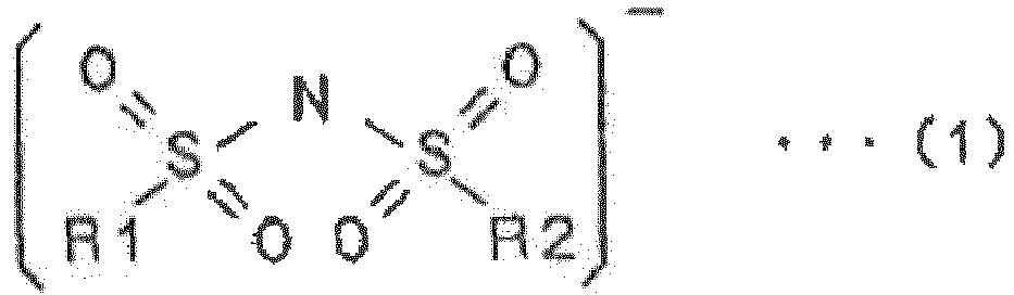
- wherein in the formula (1) R1 and R2 are the same or different and are respectively a fluoro group or a fluoralkyl group); and
- as cations, Na ion and an alkali metal ion other than Na ion or an alkaline earth metal ion, and
- the positive electrode contains, an active material, a metal oxide represented by a composition formula: NaxM1yM2-yO2, (wherein M1 is Fe or Ni, M2 is Mn orTi, x is a number satisfying 0 < x ≤ 1 and y is a number satisfying 0 < y < 1).
- the molten salt contains an anion having a chemical structure represented by the following formula (1):
- 2. The molten salt battery according to clause 1, wherein in the formula (1), R1 and R2 are respectively a fluoro group or a fluoroalkyl group having 1 to 8 carbon atoms.
- 3. The molten salt battery according to
clause 1 or 2, wherein the anion contained in the molten salt is FSA (bis(fluorosulfonyl)amide) ion, TFSA (bis(trifluoromethylsulfonyl)amide) ion or FTA (fluoro(trifluoromethylsulfonyl)amide) ion. - 4. The molten salt battery according to any one of clauses 1 to 3, wherein the cations contained in the molten salt are Na ion and K ion.
- 5. The molten salt battery according to
clause 1 or 2, wherein the molten salt is a mixed salt between NaFSA in which the cation is Na ion and the anion is FSA ion; and KFSA in which the cation is K ion and the anion is FSA ion. - 6. The molten salt battery according to any one of clauses 1 to 5, wherein the metal oxide is represented by a composition formula: Na2/3Fe1/3Mn2/3O2, Na5/6Fe1/2Mn1/2O2, NaFe1/2Ti1/2O2 or NaNi1/2Mn1/2O2.
- 7. The molten salt battery according to any one of clauses 1 to 6, further comprising a separator provided between the positive and negative electrodes,
wherein the separator is formed of a silicate glass or a resin. - 8. The molten salt battery according to clause 7, wherein the separator is formed of a glass cloth or a porous resin.
- 9. The molten salt battery according to any one of clauses 1 to 8, wherein the negative electrode contains, as an active material, tin, metal Na, carbon, silicon or indium.
- 10. The molten salt battery according to any one of clauses 1 to 9, further comprising a container formed of aluminum and configured to retain the positive and negative electrodes.
Claims (6)
- A molten salt battery comprising a battery case, a positive electrode, a separator, a negative electrode and a molten salt as an electrolyte, the positive electrode, the negative electrode and the separator being impregnated with the molten salt, wherein:the molten salt contains an anion having a chemical structure represented by a following formula (1):
 wherein in the formula (1) R1 and R2 are a fluoro group;as cations, Na ion and K ion;the molten salt is a mixed salt between NaFSA in which the cation is Na ion and the anion is FSA ion, and KFSA in which the cation is K ion and the anion is FSA ion, FSA ion being bis(fluorosulfonyl)amide ion; andthe positive electrode contains, as active material, a metal oxide represented by a composition formula: NaxM1yM21-yO2, wherein M1 is Fe or Ni, M2 is Mn or Ti, x is a number satisfying 0 < x ≤ 1 and y is a number satisfying 0 < y < 1, characterised in that:the battery case is provided with an elastic body; andwhen the positive electrode or the negative electrode is expanded or shrunk due to charge and discharge, the change in the volume of the positive electrode or the negative electrode is absorbed by expansion and contraction of the elastic body.
 - The molten salt battery according to claim 1 wherein the metal oxide is represented by a composition formula:
Na2/3Fe1/3Mn2/3O2, Na5/6Fe1/2Mn1/2O2, NaFe1/2Ti1/2O2 or NaNi1/2Mn1/2O2.
- The molten salt battery according to claim 1 or claim 2, wherein the separator is provided between the positive and negative electrodes, and
wherein the separator is formed of a silicate glass or a resin. - The molten salt battery according to claim 3, wherein the separator is formed of a glass cloth or a porous resin.
- The molten salt battery according any one of claims 1 to 4, wherein the negative electrode contains, as an active material, tin, metal Na, carbon, silicon or indium.
- The molten salt battery according any one of claims 1 to 5, further comprising a container formed of aluminium and configured to retain the positive and negative electrodes.
Applications Claiming Priority (2)
| Application Number | Priority Date | Filing Date | Title |
|---|---|---|---|
| JP2011045693A JP5775330B2 (en) | 2011-03-02 | 2011-03-02 | Molten salt battery |
| EP12752318.1A EP2683018A4 (en) | 2011-03-02 | 2012-02-22 | MIXED SALT BATTERY |
Related Parent Applications (1)
| Application Number | Title | Priority Date | Filing Date |
|---|---|---|---|
| EP12752318.1A Division EP2683018A4 (en) | 2011-03-02 | 2012-02-22 | MIXED SALT BATTERY |
Publications (1)
| Publication Number | Publication Date |
|---|---|
| EP3018739A1 true EP3018739A1 (en) | 2016-05-11 |
Family
ID=46757854
Family Applications (2)
| Application Number | Title | Priority Date | Filing Date |
|---|---|---|---|
| EP15201764.6A Ceased EP3018739A1 (en) | 2011-03-02 | 2012-02-22 | Molten salt battery |
| EP12752318.1A Withdrawn EP2683018A4 (en) | 2011-03-02 | 2012-02-22 | MIXED SALT BATTERY |
Family Applications After (1)
| Application Number | Title | Priority Date | Filing Date |
|---|---|---|---|
| EP12752318.1A Withdrawn EP2683018A4 (en) | 2011-03-02 | 2012-02-22 | MIXED SALT BATTERY |
Country Status (8)
| Country | Link |
|---|---|
| US (1) | US20130330608A1 (en) |
| EP (2) | EP3018739A1 (en) |
| JP (1) | JP5775330B2 (en) |
| KR (1) | KR101852223B1 (en) |
| CN (1) | CN103460499A (en) |
| CA (1) | CA2828350C (en) |
| TW (1) | TWI525872B (en) |
| WO (1) | WO2012117916A1 (en) |
Families Citing this family (24)
| Publication number | Priority date | Publication date | Assignee | Title |
|---|---|---|---|---|
| US10056651B2 (en) | 2010-11-05 | 2018-08-21 | Field Upgrading Usa, Inc. | Low temperature secondary cell with sodium intercalation electrode |
| US10020543B2 (en) | 2010-11-05 | 2018-07-10 | Field Upgrading Usa, Inc. | Low temperature battery with molten sodium-FSA electrolyte |
| JP5765705B2 (en) * | 2011-03-28 | 2015-08-19 | 学校法人東京理科大学 | Composite metal oxide, positive electrode active material for sodium secondary battery, positive electrode for sodium secondary battery, and sodium secondary battery |
| US10224577B2 (en) | 2011-11-07 | 2019-03-05 | Field Upgrading Usa, Inc. | Battery charge transfer mechanisms |
| JP5905381B2 (en) * | 2012-12-25 | 2016-04-20 | 東京瓦斯株式会社 | Power storage system and power storage method |
| KR20150119139A (en) * | 2013-02-11 | 2015-10-23 | 바스프 에스이 | Active cathode material and its use in rechargeable electrochemical cells |
| JP6570510B2 (en) * | 2013-03-13 | 2019-09-04 | フィールド アップグレーディング ユーエスエー・インク | Low temperature battery with molten sodium-FSA electrolyte |
| KR102195063B1 (en) * | 2013-03-13 | 2020-12-24 | 필드 업그레이딩 유에스에이, 인코포레이티드 | Low temperature secondary cell with sodium intercalation electrode |
| JP6103456B2 (en) * | 2013-03-28 | 2017-03-29 | 住友化学株式会社 | Positive electrode active material for sodium secondary battery, positive electrode for sodium secondary battery and sodium secondary battery |
| US9431656B2 (en) | 2013-05-30 | 2016-08-30 | Ceramatec, Inc. | Hybrid molten/solid sodium anode for room/intermediate temperature electric vehicle battery |
| JP2014235912A (en) * | 2013-06-03 | 2014-12-15 | 住友電気工業株式会社 | Sodium molten salt battery and method for manufacturing the same |
| KR20160016922A (en) | 2013-06-06 | 2016-02-15 | 세라마테크, 인코오포레이티드 | Low viscosity/high conductivity sodium haloaluminate electrolyte |
| JP2015022868A (en) * | 2013-07-18 | 2015-02-02 | 住友電気工業株式会社 | Molten salt battery |
| EP3044824B1 (en) | 2013-09-05 | 2021-01-06 | Field Upgrading USA, Inc. | High temperature sodium battery with high energy efficiency |
| US9537179B2 (en) | 2013-09-25 | 2017-01-03 | Ceramatec, Inc. | Intermediate temperature sodium-metal halide battery |
| JP6682427B2 (en) * | 2013-09-25 | 2020-04-15 | フィールド アップグレーディング ユーエスエー・インク | Medium temperature sodium-metal halide battery |
| KR102192082B1 (en) | 2013-10-18 | 2020-12-16 | 삼성전자주식회사 | Anode active material, anode including the anode active material, and lithium secondary battery including the anode |
| KR102149334B1 (en) | 2013-10-21 | 2020-08-28 | 삼성전자주식회사 | cathode active material and cathode and sodium secondary battery using the same |
| JP6189233B2 (en) * | 2014-03-10 | 2017-08-30 | 住友電気工業株式会社 | Sodium molten salt battery and method of using the same |
| JP6349998B2 (en) | 2014-06-17 | 2018-07-04 | 住友電気工業株式会社 | Sodium ion secondary battery |
| KR101610014B1 (en) * | 2014-09-16 | 2016-04-11 | 전자부품연구원 | Electrolyte solution comprising sulfur dioxide based ionic liquid electrolyte and sodium-sulfur dioxide secondary battery having the same |
| TWI597887B (en) * | 2014-11-13 | 2017-09-01 | 日本曹達股份有限公司 | Negative electrode composition for power storage device, negative electrode including the same, and power storage device, and method for producing negative electrode for power storage device |
| US10734686B2 (en) | 2015-04-17 | 2020-08-04 | Field Upgrading Usa, Inc. | Sodium-aluminum battery with sodium ion conductive ceramic separator |
| US11267707B2 (en) | 2019-04-16 | 2022-03-08 | Honeywell International Inc | Purification of bis(fluorosulfonyl) imide |
Citations (9)
| Publication number | Priority date | Publication date | Assignee | Title |
|---|---|---|---|---|
| JP2002008598A (en) * | 2000-06-21 | 2002-01-11 | Mitsubishi Heavy Ind Ltd | Rechargeable battery |
| JP2007273297A (en) | 2006-03-31 | 2007-10-18 | Ngk Insulators Ltd | Sodium-sulfur battery |
| EP1862452A1 (en) * | 2005-03-23 | 2007-12-05 | Kyoto University | Molten salt composition and use thereof |
| DE102007009295A1 (en) * | 2007-02-16 | 2008-08-21 | Varta Microbattery Gmbh | Galvanic element with high capacity |
| WO2009016510A2 (en) * | 2007-07-27 | 2009-02-05 | Toyota Jidosha Kabushiki Kaisha | Solid-state battery |
| JP2009067644A (en) * | 2007-09-14 | 2009-04-02 | Kyoto Univ | Molten salt composition and use thereof |
| JP2009259601A (en) * | 2008-04-16 | 2009-11-05 | Sumitomo Chemical Co Ltd | Electrode active material for sodium ion secondary battery and its method for manufacturing |
| EP2216298A1 (en) * | 2007-11-09 | 2010-08-11 | Sumitomo Chemical Company, Limited | Complex metal oxide and sodium secondary battery |
| EP2242131A1 (en) * | 2008-02-04 | 2010-10-20 | Sumitomo Chemical Company, Limited | Composite metal oxide and sodium rechargeable battery |
Family Cites Families (11)
| Publication number | Priority date | Publication date | Assignee | Title |
|---|---|---|---|---|
| JPS5311060B2 (en) * | 1973-08-09 | 1978-04-19 | ||
| JPS5539124A (en) * | 1978-09-13 | 1980-03-18 | Nobuyuki Koura | A *a c 3 nac *fes2* system melting salt secondary cell |
| JPH08203331A (en) * | 1995-01-24 | 1996-08-09 | Toshiba Corp | Insulation tape, insulation coil, and superconducting magnet |
| US20040121200A1 (en) * | 2002-12-24 | 2004-06-24 | Richard Johnsen | Inactive end cell assembly for fuel cells for improved electrolyte management and electrical contact |
| KR100561298B1 (en) * | 2004-01-13 | 2006-03-15 | 삼성에스디아이 주식회사 | Secondary battery |
| JP4199282B2 (en) * | 2007-05-14 | 2008-12-17 | 株式会社東芝 | Nonaqueous electrolyte secondary battery |
| JP5159681B2 (en) * | 2009-03-25 | 2013-03-06 | 株式会社東芝 | Non-aqueous electrolyte battery |
| JP5670339B2 (en) * | 2009-09-28 | 2015-02-18 | 住友電気工業株式会社 | Battery and energy system |
| CN102318127B (en) * | 2010-01-13 | 2015-07-15 | 松下电器产业株式会社 | Lithium ion secondary battery and manufacturing method thereof |
| JP5779050B2 (en) * | 2010-11-30 | 2015-09-16 | 住友電気工業株式会社 | Molten salt battery |
| JP5810823B2 (en) * | 2011-10-19 | 2015-11-11 | 住友電気工業株式会社 | Sodium molten salt battery electrode, sodium molten salt battery, and method of using sodium molten salt battery |
-
2011
- 2011-03-02 JP JP2011045693A patent/JP5775330B2/en not_active Expired - Fee Related
-
2012
- 2012-02-22 WO PCT/JP2012/054275 patent/WO2012117916A1/en not_active Ceased
- 2012-02-22 CA CA2828350A patent/CA2828350C/en not_active Expired - Fee Related
- 2012-02-22 EP EP15201764.6A patent/EP3018739A1/en not_active Ceased
- 2012-02-22 US US14/002,301 patent/US20130330608A1/en not_active Abandoned
- 2012-02-22 KR KR1020137022759A patent/KR101852223B1/en not_active Expired - Fee Related
- 2012-02-22 EP EP12752318.1A patent/EP2683018A4/en not_active Withdrawn
- 2012-02-22 CN CN2012800109658A patent/CN103460499A/en active Pending
- 2012-02-24 TW TW101106243A patent/TWI525872B/en not_active IP Right Cessation
Patent Citations (9)
| Publication number | Priority date | Publication date | Assignee | Title |
|---|---|---|---|---|
| JP2002008598A (en) * | 2000-06-21 | 2002-01-11 | Mitsubishi Heavy Ind Ltd | Rechargeable battery |
| EP1862452A1 (en) * | 2005-03-23 | 2007-12-05 | Kyoto University | Molten salt composition and use thereof |
| JP2007273297A (en) | 2006-03-31 | 2007-10-18 | Ngk Insulators Ltd | Sodium-sulfur battery |
| DE102007009295A1 (en) * | 2007-02-16 | 2008-08-21 | Varta Microbattery Gmbh | Galvanic element with high capacity |
| WO2009016510A2 (en) * | 2007-07-27 | 2009-02-05 | Toyota Jidosha Kabushiki Kaisha | Solid-state battery |
| JP2009067644A (en) * | 2007-09-14 | 2009-04-02 | Kyoto Univ | Molten salt composition and use thereof |
| EP2216298A1 (en) * | 2007-11-09 | 2010-08-11 | Sumitomo Chemical Company, Limited | Complex metal oxide and sodium secondary battery |
| EP2242131A1 (en) * | 2008-02-04 | 2010-10-20 | Sumitomo Chemical Company, Limited | Composite metal oxide and sodium rechargeable battery |
| JP2009259601A (en) * | 2008-04-16 | 2009-11-05 | Sumitomo Chemical Co Ltd | Electrode active material for sodium ion secondary battery and its method for manufacturing |
Non-Patent Citations (4)
| Title |
|---|
| JUN'ICHI IWADATE ET AL: "Sojo NaM02(M=Fe, Mn, Ti) no Gosei to Denki Kagaku Tokusei [Synthesis and Electrochemical Property of Layered NaMO2 (M = Fe, Mn and Ti)", BATTERY SYMPOSIUM IN JAPAN KOEN YOSHISHU 51.-DENCHI-TORONKAI : NOVEMBER 9 - 11, 2010, NAGOYA = THE 51ST BATTERY SYMPOSIUM IN J, DENKI KAGAKKAI, JP; NAGOYA, JAPAN, vol. 51, 8 November 2010 (2010-11-08), pages 225, XP008170720 * |
| JUN-ICHI IWATATE; NAOAKI YABU-UCHI; SHIN-ICHI KOMABA: "Abstract of The 51st Battery Symposium in Japan", November 2010, THE ELECTROCHEMICAL SOCIETY OF JAPAN, article "Synthesis of laminated NaM0 (M = Fe, Mn, Ti) and Electrochemical property", pages: 225 |
| KUBOTA K ET AL: "Novel inorganic ionic liquids possessing low melting temperatures and wide electrochemical windows: Binary mixtures of alkali bis(fluorosulfonyl)amides", ELECTROCHEMISTRY COMMUNICATIONS, ELSEVIER, AMSTERDAM, NL, vol. 10, no. 12, 7 October 2008 (2008-10-07), pages 1886 - 1888, XP025679958, ISSN: 1388-2481, [retrieved on 20081119], DOI: 10.1016/J.ELECOM.2008.10.001 * |
| SHINICHI KOMABA ET AL: "Electrochemically Reversible Sodium Intercalation of Layered NaNi0.5Mn0.5O2 and NaCrO2", ECS TRANSACTIONS, 15 May 2009 (2009-05-15), pages 43 - 55, XP055171773, DOI: 10.1149/1.3112727 * |
Also Published As
| Publication number | Publication date |
|---|---|
| CN103460499A (en) | 2013-12-18 |
| CA2828350C (en) | 2018-11-27 |
| CA2828350A1 (en) | 2012-09-07 |
| JP5775330B2 (en) | 2015-09-09 |
| KR20140021547A (en) | 2014-02-20 |
| TW201242139A (en) | 2012-10-16 |
| US20130330608A1 (en) | 2013-12-12 |
| EP2683018A4 (en) | 2014-08-20 |
| WO2012117916A1 (en) | 2012-09-07 |
| KR101852223B1 (en) | 2018-04-25 |
| TWI525872B (en) | 2016-03-11 |
| JP2012182087A (en) | 2012-09-20 |
| EP2683018A1 (en) | 2014-01-08 |
Similar Documents
| Publication | Publication Date | Title |
|---|---|---|
| CA2828350C (en) | Nonvolatile and nonflammable molten salt battery | |
| KR101822217B1 (en) | Molten salt battery | |
| JP4455461B2 (en) | Power storage system | |
| CN105990576B (en) | Electrode, nonaqueous electrolyte battery, and battery pack | |
| CN102403529B (en) | Non-aqueous electrolyte secondary battery | |
| JP5225342B2 (en) | Battery electrode and method for manufacturing the same, non-aqueous electrolyte battery, battery pack and active material | |
| KR20160100948A (en) | Molten-salt battery, charge-discharge method, and charge-discharge system | |
| JPH04328278A (en) | Nonaqueous electrolyte secondary battery | |
| JP7676564B2 (en) | SO2-based electrolyte for rechargeable battery cells and rechargeable battery cells | |
| CN101232088B (en) | Battery | |
| CN113039671A (en) | Electrochemical cell with lithium-stuffed garnet separator and catholyte additive | |
| JP6460511B2 (en) | Active material for lithium secondary battery, method for producing the same, and lithium secondary battery using the same | |
| WO2015194372A1 (en) | Sodium ion secondary cell | |
| EP2744035B1 (en) | Metal-oxygen battery and method for producing oxygen storage material used therein | |
| JP5471905B2 (en) | Molten salt battery | |
| JP2010040180A (en) | Power storage device | |
| JP4862356B2 (en) | Negative electrode active material and aqueous lithium secondary battery | |
| JP6054575B1 (en) | Nonaqueous electrolyte battery and battery pack | |
| JPS63114065A (en) | Organic electrolyte secondary battery | |
| JP2008153045A (en) | Negative electrode material for non-aqueous secondary battery and non-aqueous secondary battery using the same | |
| JP4862357B2 (en) | Negative electrode active material and aqueous lithium secondary battery | |
| JPH04296471A (en) | Non-aqueous electrolyte secondary battery | |
| JPH09312170A (en) | Non-aqueous electrolyte battery |
Legal Events
| Date | Code | Title | Description |
|---|---|---|---|
| PUAI | Public reference made under article 153(3) epc to a published international application that has entered the european phase |
Free format text: ORIGINAL CODE: 0009012 |
|
| AC | Divisional application: reference to earlier application |
Ref document number: 2683018 Country of ref document: EP Kind code of ref document: P |
|
| AK | Designated contracting states |
Kind code of ref document: A1 Designated state(s): AL AT BE BG CH CY CZ DE DK EE ES FI FR GB GR HR HU IE IS IT LI LT LU LV MC MK MT NL NO PL PT RO RS SE SI SK SM TR |
|
| 17P | Request for examination filed |
Effective date: 20160826 |
|
| RBV | Designated contracting states (corrected) |
Designated state(s): AL AT BE BG CH CY CZ DE DK EE ES FI FR GB GR HR HU IE IS IT LI LT LU LV MC MK MT NL NO PL PT RO RS SE SI SK SM TR |
|
| 17Q | First examination report despatched |
Effective date: 20170127 |
|
| 18R | Application refused |
Effective date: 20180217 |