EP3018680A1 - Membrane and seat device - Google Patents
Membrane and seat device Download PDFInfo
- Publication number
- EP3018680A1 EP3018680A1 EP14819347.7A EP14819347A EP3018680A1 EP 3018680 A1 EP3018680 A1 EP 3018680A1 EP 14819347 A EP14819347 A EP 14819347A EP 3018680 A1 EP3018680 A1 EP 3018680A1
- Authority
- EP
- European Patent Office
- Prior art keywords
- flame retardant
- membrane
- film
- retardant material
- layer
- Prior art date
- Legal status (The legal status is an assumption and is not a legal conclusion. Google has not performed a legal analysis and makes no representation as to the accuracy of the status listed.)
- Granted
Links
Images


Classifications
-
- H—ELECTRICITY
- H01—ELECTRIC ELEMENTS
- H01H—ELECTRIC SWITCHES; RELAYS; SELECTORS; EMERGENCY PROTECTIVE DEVICES
- H01H3/00—Mechanisms for operating contacts
- H01H3/02—Operating parts, i.e. for operating driving mechanism by a mechanical force external to the switch
- H01H3/14—Operating parts, i.e. for operating driving mechanism by a mechanical force external to the switch adapted for operation by a part of the human body other than the hand, e.g. by foot
- H01H3/141—Cushion or mat switches
-
- B—PERFORMING OPERATIONS; TRANSPORTING
- B60—VEHICLES IN GENERAL
- B60N—SEATS SPECIALLY ADAPTED FOR VEHICLES; VEHICLE PASSENGER ACCOMMODATION NOT OTHERWISE PROVIDED FOR
- B60N2/00—Seats specially adapted for vehicles; Arrangement or mounting of seats in vehicles
- B60N2/002—Seats provided with an occupancy detection means mounted therein or thereon
- B60N2/0021—Seats provided with an occupancy detection means mounted therein or thereon characterised by the type of sensor or measurement
- B60N2/003—Seats provided with an occupancy detection means mounted therein or thereon characterised by the type of sensor or measurement characterised by the sensor mounting location in or on the seat
- B60N2/0033—Seats provided with an occupancy detection means mounted therein or thereon characterised by the type of sensor or measurement characterised by the sensor mounting location in or on the seat mounted on or in the foam cushion
-
- B—PERFORMING OPERATIONS; TRANSPORTING
- B60—VEHICLES IN GENERAL
- B60N—SEATS SPECIALLY ADAPTED FOR VEHICLES; VEHICLE PASSENGER ACCOMMODATION NOT OTHERWISE PROVIDED FOR
- B60N2/00—Seats specially adapted for vehicles; Arrangement or mounting of seats in vehicles
- B60N2/58—Seat coverings
-
- B—PERFORMING OPERATIONS; TRANSPORTING
- B60—VEHICLES IN GENERAL
- B60R—VEHICLES, VEHICLE FITTINGS, OR VEHICLE PARTS, NOT OTHERWISE PROVIDED FOR
- B60R21/00—Arrangements or fittings on vehicles for protecting or preventing injuries to occupants or pedestrians in case of accidents or other traffic risks
- B60R21/01—Electrical circuits for triggering passive safety arrangements, e.g. airbags, safety belt tighteners, in case of vehicle accidents or impending vehicle accidents
- B60R21/015—Electrical circuits for triggering passive safety arrangements, e.g. airbags, safety belt tighteners, in case of vehicle accidents or impending vehicle accidents including means for detecting the presence or position of passengers, passenger seats or child seats, and the related safety parameters therefor, e.g. speed or timing of airbag inflation in relation to occupant position or seat belt use
- B60R21/01512—Passenger detection systems
- B60R21/01516—Passenger detection systems using force or pressure sensing means
- B60R21/01524—Passenger detection systems using force or pressure sensing means using electric switches
-
- B—PERFORMING OPERATIONS; TRANSPORTING
- B60—VEHICLES IN GENERAL
- B60N—SEATS SPECIALLY ADAPTED FOR VEHICLES; VEHICLE PASSENGER ACCOMMODATION NOT OTHERWISE PROVIDED FOR
- B60N2210/00—Sensor types, e.g. for passenger detection systems or for controlling seats
- B60N2210/10—Field detection presence sensors
- B60N2210/12—Capacitive; Electric field
-
- H—ELECTRICITY
- H01—ELECTRIC ELEMENTS
- H01H—ELECTRIC SWITCHES; RELAYS; SELECTORS; EMERGENCY PROTECTIVE DEVICES
- H01H9/00—Details of switching devices, not covered by groups H01H1/00 - H01H7/00
- H01H9/02—Bases, casings, or covers
- H01H9/04—Dustproof, splashproof, drip-proof, waterproof, or flameproof casings
Definitions
- the present invention relates to a membrane and a seat device.
- a seating sensor for detecting whether or not a passenger is seated is provided on a seat of an automobile. If such seating sensor is configured by a membrane, such membrane sometimes includes a first film with a first wiring. Additionally, an inexpensive raw material such as a PET film and a PEN film is sometimes used for the first film.
- Patent Literature 1 JP 2012-121364 A
- the PET, the PEN, and the like are inexpensive, but have a relatively small heat capacity. Therefore, when a combustion test is performed on the membrane, the film, and the like at the periphery of the wiring are combusted when the first wiring reaches a high temperature by greater than or equal to a certain extent. Furthermore, when the film and the like at the periphery of the wiring are combusted, the wiring may sag by its own weight. In this case, the molten film flows along the sagged wiring, thus acting as a fuel and increasing the force of the fire at the periphery of the distal end of the sagged wiring, and the entire membrane may be burnt by a high temperature outer flame part of the fire of the relevant portion.
- the object of the present invention is to provide a membrane excelling in flame retardancy, and a seat device using the same.
- a membrane according to the present invention includes a first film having at least a first wiring.
- a layer of flame retardant material is formed on a surface not formed with the first wiring of the first film.
- the layer contains an organic substance and phosphorus, and that forms a layer of carbide for physically supporting the first wiring by combustion.
- the membrane according to the present invention includes the layer of flame retardant material that forms a layer of carbide (char) for physically supporting the first wiring by combustion. Therefore, the wiring can be prevented from sagging. Additionally, the supply of oxygen to the combusting portion can be shielded by the char. Moreover, since the char has low thermal conductivity, the conduction of heat to the membrane can be significantly reduced. Therefore, the flame retardancy of the membrane can be enhanced. Note that in the membrane according to the present invention, the flame retardant material contains the organic substance and the phosphorus. Therefore, at the time of combustion of the membrane, a char having the organic substance as a material can be formed and the formation of such char can be promoted with the phosphorus.
- char carbide
- the organic substance may be a polyester resin.
- the polyester resin has high polymerization degree compared to the other resins, and thus has high durability, strong withstanding to pulling, and also flexibility so as to have strong withstanding to stress as well.
- the organic substance may contain carboxyl group (COOH).
- COOH carboxyl group
- the phosphorus may be bonded to a side chain of the organic substance. That is, if the organic substance and the phosphorus exist independently in the flame retardant material layer, the proportion of the concentration of the organic substance and the phosphorus may vary within the plane in the flame retardant material. In such a case, for example, the char is less likely to be formed at the portion where the amount of phosphorus is small in the membrane, and such portion tends to relatively easily burn. Additionally, at where the phosphorus exists in excess, the phosphorus may precipitate to the surface. On the contrary, in the present embodiment, the phosphorus is bonded to the side chain of the organic substance. Therefore, the variation within the plane of the proportion of the organic substance and the phosphorus can be prevented, and the char can be appropriately formed at the time of the combustion of the membrane.
- the flame retardant material may contain ester phosphate.
- the flame retardant material containing the ester phosphate forms a composite film (char), which includes the polyphosphoric acid and a carbide layer on the combustion surface and thus can suitably form the char.
- the polyphosphoric acid is generated from a phosphorus compound.
- the carbide layer is generated from a dehydrated ester polymer.
- the film thickness of the layer of flame retardant material may be greater than or equal to one twentieth and smaller than or equal to one third of a film thickness of a film brought into contact with the layer of flame retardant material and physically supported by the layer of carbide. That is, in view of the mechanical rigidity of the char or the like, the film thickness of the layer of flame retardant material is desirably greater than or equal to one twentieth of the film thickness of the film to support the first wiring, the molten resin, and the like with the char. Additionally, upon using the membrane, the film thickness of the layer of flame retardant material is desirably smaller than or equal to one third of the film thickness of the film so that the properties originally possessed by the film such as flexibility are not affected.
- the film thickness of the layer of flame retardant material may be greater than or equal to 20 ⁇ m and smaller than or equal to 100 ⁇ m. That is, in view of the mechanical rigidity of the char or the like, the film thickness of the layer of flame retardant material is desirably greater than or equal to 20 ⁇ m to support the first wiring, the molten resin, and the like with the char. Additionally, upon using the membrane, the film thickness of the layer of flame retardant material is desirably smaller than or equal to 100 ⁇ m so that the properties originally possessed by the film are not affected.
- the membrane may further include a cushion material provided via the layer of flame retardant material.
- a cushion material provided via the layer of flame retardant material.
- the membrane includes a switch that is turned to an ON state by a load, by providing the cushion material, when the load is applied, the cushion material is moved so as to enter an opening of the membrane so that the load can be easily propagated to the switch.
- the ignition to the membrane can be suitably prevented even if the cushion material is ignited, for example, and furthermore, even the flame retardancy in the cushion material can be enhanced by shielding the thermal conduction.
- a seat device includes: a cushion pad on which a passenger of an automobile sits; and any one of the membranes to be attached to the cushion pad, the layer of flame retardant material being formed on a surface not facing the cushion pad of the first film.
- a membrane excelling in flame retardancy and a seat device using the same can be provided.
- Fig. 1 is a plan view for describing a membrane and a seat device according to the present embodiment
- Fig. 2 is a side view
- Fig. 3 is a cross-sectional view cut along a line A-A' of Fig. 1
- Fig. 4 is a plan view of a membrane 3.
- the seat device according to the present embodiment includes a seat 1, a seat pan 2 for installing the seat 1, and the membrane 3 for detecting the seating of the passenger.
- a membrane switch having a three-layer structure is adopted for the membrane 3, but other configurations may be adopted.
- the membrane 3 is provided at a portion on a rear side of an opening 22 of an installing surface 21 of the seat pan 2 , and as shown in Fig. 4 , includes a sensor stem part 31 extended in a direction orthogonal to an advancing direction of an automobile, a sensor side part 32 and a sensor side part 33 provided on the left and right of the opening 22 of the installing surface 21, connected to both ends of the sensor stem part 31, and extended in the advancing direction of the automobile, and a tail part 34 connected to a center position of the sensor stem part 31 and extended in the advancing direction of the automobile.
- the tail part 34 is attached to a back surface of the installing surface 21 via the opening 22 (see Fig.
- the membrane 3 may be provided so that, for example, the sensor stem part 31 is located on a front side of the opening 22.
- a switch 321 and a switch 331 are provided at the front end portions of the sensor side parts 32 and 33, respectively.
- a switch 322 and a switch 332 are provided at the back end portions of the sensor side parts 32 and 33, respectively.
- the switches 321, 322, 331, and 332 can, for example, be formed from a pair of electrodes formed on the surfaces facing each other through a space formed by a spacer, in which case, the electrode can be brought into contact by pushing to obtain conduction.
- the switches 321, 322, 331, and 332 can adopt a configuration capable of detecting the pressure and obtaining electrical conduction.
- Fig. 5 is a side view cut along a line B-B' of Fig. 4 .
- the membrane 3 includes a first film 35 with a first wiring 351, a spacer 36 stacked on a surface formed with the first wiring 351 of the first film 35 and having an opening 36a at one part, and a second film 37 stacked on the spacer 36 and having a second wiring 371 that configures an electrical circuit with the first wiring 351.
- a flame retardant material layer 38 containing an organic substance and phosphorus is formed on a surface not formed with the first wiring 351 of the first film 35.
- the first film 35 includes a cushion material 39 via such flame retardant material layer 38.
- the first film 35, the spacer 36, and the second film 37 can be generated from a resin having flexibility such as polyethylene terephthalate (PET), polyethylene naphthalate (PEN).
- the first wiring 351 and the second wiring 371 can be formed by printing a metal such as silver, carbon paste, and the like on such resin.
- Fig. 6 is a circuit diagram showing a circuit configuration of the membrane 3. That is, the membrane 3 is formed from a series circuit obtained by connecting, in series, a terminal 341 provided on the tail part 34 , a parallel circuit including the switches 321 and 322 provided on the sensor side part 32, a parallel circuit including the switches 331 and 332 provided on the sensor side part 33, and a terminal 342 provided on the tail part 34.
- the terminal 341 and the terminal 342 provided on the tail part 34 are connected to the control unit 5 on the back side of the installing surface 21, and a potential difference is supplied thereto. Therefore, when the passenger sits on the seat 1, the upper surface of the seating sensor 3 is pushed.
- Fig. 7 is schematic views describing a phenomenon in the combustion of a membrane 3' according to a comparative example.
- the membrane 3' according to the comparative example is basically configured substantially similar to the membrane 3 according to the present embodiment, but differs in that the flame retardant material layer 38 is not provided.
- the seat pan 2 is often formed from a material that does not have flexibility, and hence an appropriate load may not be propagated to the membrane 3 from the seat pan 2, and the load may not be appropriately detected.
- the cushion material 39 is interposed between the seat pan 2 and the first film 35.
- the cushion material 39 is moved to enter the opening 22 of the membrane 3, so that the load can be appropriately propagated to the membrane 3.
- the cushion material 39 generally has a small heat capacity compared to the seat pan 2, the cushion material 39 has a possibility of being ignited before the membrane 3 when an excessive heat is applied.
- the film, and the like at the periphery of the wiring are sometimes combusted when the first wiring 351 or the second wiring 371 reaches a high temperature by greater than or equal to a certain extent.
- the wiring may sag by its own weight. In this case, the molten film flows along the sagged wiring, thus acting as a fuel and increasing the force of the fire at the periphery of the distal end of the sagged wiring.
- the entire membrane 3' may be burnt by a high temperature outer flame part of the fire of the relevant portion.
- the membrane 3 according to the present embodiment includes the flame retardant material layer 38, which contains an organic substance or phosphorus, between the first film 35 and the cushion material 39.
- the membrane 3 according to the present embodiment includes the cushion material 39, and hence the load can be appropriately propagated to the membrane 3, similar to the comparative example.
- the flame retardant material containing the organic substance and the phosphorus forms a char (carbide) 38' having the organic substance as the material on a combustion surface.
- the phosphorus in the flame retardant material layer promotes the change of the organic substance to the char in the combustion. Therefore, as shown in Fig.
- the first wiring 351 or the second wiring 371 is physically supported by the char 38' so that the sagging of the wiring can be prevented. Additionally, as shown in Fig. 8(b) , the supply of oxygen to the combusting portion can be shielded by the char 38'. Moreover, as shown in Fig. 8(c) , the thermal conduction from the cushion material 39 to the first film 35 can be significantly reduced since the char 38' has a low thermal conductivity. Therefore, the flame retardancy of the membrane 3 can be enhanced.
- the flame retardant material layer 34 is generated by applying the flame retardant material, in a paste form, containing the organic substance and the phosphorus on the first film 35.
- the organic substance contained in the flame retardant material may be, for example, polyester resin, epoxy resin, and the like.
- the polyester resin has a high polymerization degree compared to the other resins, and thus has high durability, strong withstanding to pulling, and also flexibility so as to have strong withstanding to stress as well. Therefore, the polyester resin is suitable for the organic substance in the flame retardant material.
- the organic substance may contain carboxyl group (COOH).
- COOH carboxyl group
- the phosphorus contained in the flame retardant material maybe bonded to the side chain of the organic substance. That is, if the organic substance and the phosphorus exist independently in the flame retardant material layer, the proportion of the concentration of the organic substance and the phosphorus may vary within the plane in the flame retardant material. In such a case, for example, the char is less likely to be formed at the portion where the amount of phosphorus is small in the membrane, and such portion tends to relatively easily burn. Additionally, at where the phosphorus exists in excess, the phosphorus may precipitate to the surface. On the contrary, in the present embodiment, the phosphorus is bonded to the side chain of the organic substance. Therefore, the variation within the plane of the proportion of the organic substance and the phosphorus can be prevented, and the char can be appropriately formed at the time of the combustion of the membrane.
- the flame retardancy can be more suitably enhanced by using the flame retardant material containing ester phosphate as the flame retardant material containing the organic substance and the phosphorus.
- the flame retardant material containing the ester phosphate forms a composite film (char), which includes the polyphosphoric acid and a carbide layer on the combustion surface and thus can suitably form the char.
- the polyphosphoric acid is generated from a phosphorus compound.
- the carbide layer is generated from a dehydrated ester polymer.
- the flame retardant material containing the ester phosphate for example, application of a material of aromatic ester phosphate series (triphenylphosphate, etc.), a material of aromatic condensed ester phosphate series (1,3-phenylene bis (diphenylphosphate), etc.), a material of halogen containing ester phosphate series (tris (dichloropropyl) phosphate, etc.), a material of halogen containing condensed ester phosphate series (polyoxy alkylene bis dichloro alkyl phosphate etc.) can be considered.
- a flame retardant material other than the flame retardant material containing the ester phosphate can be used, and for example, a material of red phosphorus series (e.g., red phosphorus) can be applied for such flame retardant material.
- the flame retardant material containing the organic substance and the phosphorus on, for example, the first film 35 Upon performing the application, the flame retardant material is applied on the first film 35 as a paste containing a solvent. Thereafter, the applied paste is dried to form the flame retardant material layer 38.
- the solvent contained in the paste for example, application of that of diethylene glycol monoethyl ether acetate (CH 3 COOC 2 H 4 OC 2 H 4 OC 2 H 5 ) having a viscosity of 150 to 250 dPa ⁇ s is considered.
- the membrane 3 according to the present embodiment forms the char 38' at the time of the combustion firstly, to physically support the wirings 351, 371, secondly, to shield the supply of oxygen, and thirdly, to shield the thermal conduction. Therefore, the range of the film thickness of the flame retardant material layer 38 needs to be determined in view of the mechanical rigidity of the formed char, the shielding property of the oxygen, the thermal conductivity, and the like. The film thickness of the flame retardant material layer 38 will now be reviewed.
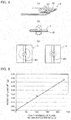
- Fig. 9 is a graph showing a relationship of the film thickness of the flame retardant material layer 38, and the weight of the char 38' formed after the membrane 3 is combusted. As shown in Fig. 9 , it is found that the weight of the formed char 38' increases in proportion to the film thickness of the flame retardant material layer 38. Therefore, the amount of formed char 38' can be suitably controlled by the film thickness of the flame retardant material layer 38.
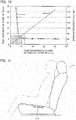
- Fig. 10 is a graph showing a relationship of the film thickness of the flame retardant material layer 38 and the film thickness and the combustion speed of the char 38'. According to the figure, it is found that the combustion speed is suppressed to smaller than or equal to 50 mm/min when the film thickness of the flame retardant material layer 38 is greater than or equal to 20 ⁇ m, whereas the combustion speed rapidly increased when the film thickness is, for example, 10 ⁇ m. This is because if the film thickness is set to 10 ⁇ m, the generated char 38' breaks without being able to support the wiring, the dissolved resin, and the like, and the sagging described above occurs. Note that the total thickness of the membrane 3 was 400 ⁇ m.
- the film thickness of the flame retardant material layer 38 that does not cause mechanical breakage of the char 38' changes according to the film thickness of the film physically supported by the char 38' such as the first film 35.
- the film thickness of the flame retardant material layer 38 may become uneven in the process of applying the flame retardant material on the first film 35.
- the inventors assumed that the film thickness of the flame retardant material layer 38 that does not cause mechanical breakage of the char 38' is t2 ⁇ t1/20, where t1 is the film thickness of the film physically supported by the char 38' such as the first film 35 or the second film 37, and t2 is the film thickness of the flame retardant material layer 38.
- the film thickness t1 of the film physically supported by the char 38' is, for example, the sum of the film thicknesses of the first and second films. If the membrane 3 further includes films to be supported at the time of the combustion, the film thickness becomes a size including the film thickness of the relevant films. Moreover, if only one layer exists for the film to be physically supported by the char 38', as shown in a third embodiment to be described later, the film thickness of the film physically supported by the char 38' becomes equal to the film thickness of such film. Furthermore, if another layer is configured from a different material, the weight, and the like of the relevant layer also need to be considered. If the first film 35, and the like, and the type of flame retardant material differ from the present embodiment, such embodiment also needs to be taken into consideration.
- the film thickness of the flame retardant material layer 38 is assumed to be greater than or equal to 20 ⁇ m. Note that the flame retardant material is desirably applied over the entire surface of the first film 35, but even if the flame retardant material is applied to only one part, the mechanical strength can be ensured and the heat insulating effect can be exhibited.
- the membrane 3 includes the switches 321, 322, 331, and 332, which are turned to the ON state by pushing. Therefore, if the flame retardant material layer 38 is too thick, the film is less likely to bend, and an ON load for turning the switches to the ON state becomes high.
- the film thickness of the flame retardant material layer 38 is desirably smaller than or equal to 100 ⁇ m. Thus, the ON load can be adjusted to an appropriate range.
- the appropriate film thickness of the flame retardant material layer 38 of when the ON load is taken into consideration varies according to the film thickness of the film.
- the film thickness t2 of the flame retardant material layer 38 is desirably t2 ⁇ t1/3, where t1 is the film thickness of the film physically supported by the char 38' such as the first film 35 or the second film 37, and t2 is the film thickness of the flame retardant material layer 38.
- the ON load can be adjusted to an appropriate range.
- the film thickness t2 of the flame retardant material layer 38 is more desirably t2 ⁇ t1/5.
- Fig. 11 is a side view for describing the membrane 3-2 and the seat device according to the present embodiment.
- the membrane 3 is installed between the seat 1 and the seat pan 2, but in the present embodiment, the membrane 3-2 is installed on the seating face of a seat 1.
- a cushion material 39 is formed on a side not facing the seat 1, and a flame retardant material layer 38 is formed between the cushion material and a first film 35 or a second film 37.
- the flame retardant material layer 38 may be formed on a surface not facing the seat 1 of a surface not formed with a first wiring 351 of the first film 35 and a surface 371 not formed with a second wiring of the second film 37, or may be formed on an open space side of such surfaces. Additionally, in the present embodiment, the cushion material 39 is formed via the flame retardant material layer 38, but the cushion material 39 sometimes may not be formed.
- the membrane switch having a three-layer structure is adopted for the membrane.
- a capacitance sensor having a one-layer structure is adopted for the membrane.
- the membrane and the seat device according to the present embodiment are similar to the first and second embodiments with regards to the other aspects.
- the membrane excelling flame retardancy and the seat device using the same can be supplied by providing the flame retardant material layer 38.
- the membrane has a one-layer structure. Therefore, if other layers are not formed in the membrane, the film physically supported by a char 38' is only one layer.
Landscapes
- Engineering & Computer Science (AREA)
- Mechanical Engineering (AREA)
- Aviation & Aerospace Engineering (AREA)
- Transportation (AREA)
- Laminated Bodies (AREA)
- Switches Operated By Changes In Physical Conditions (AREA)
- Push-Button Switches (AREA)
- Compositions Of Macromolecular Compounds (AREA)
Description
- The present invention relates to a membrane and a seat device.
- A seating sensor for detecting whether or not a passenger is seated is provided on a seat of an automobile. If such seating sensor is configured by a membrane, such membrane sometimes includes a first film with a first wiring. Additionally, an inexpensive raw material such as a PET film and a PEN film is sometimes used for the first film.
- Patent Literature 1:
JP 2012-121364 A - The PET, the PEN, and the like are inexpensive, but have a relatively small heat capacity. Therefore, when a combustion test is performed on the membrane, the film, and the like at the periphery of the wiring are combusted when the first wiring reaches a high temperature by greater than or equal to a certain extent. Furthermore, when the film and the like at the periphery of the wiring are combusted, the wiring may sag by its own weight. In this case, the molten film flows along the sagged wiring, thus acting as a fuel and increasing the force of the fire at the periphery of the distal end of the sagged wiring, and the entire membrane may be burnt by a high temperature outer flame part of the fire of the relevant portion. In light of the foregoing problem, the object of the present invention is to provide a membrane excelling in flame retardancy, and a seat device using the same.
- A membrane according to the present invention includes a first film having at least a first wiring. A layer of flame retardant material is formed on a surface not formed with the first wiring of the first film. The layer contains an organic substance and phosphorus, and that forms a layer of carbide for physically supporting the first wiring by combustion.
- The membrane according to the present invention includes the layer of flame retardant material that forms a layer of carbide (char) for physically supporting the first wiring by combustion. Therefore, the wiring can be prevented from sagging. Additionally, the supply of oxygen to the combusting portion can be shielded by the char. Moreover, since the char has low thermal conductivity, the conduction of heat to the membrane can be significantly reduced. Therefore, the flame retardancy of the membrane can be enhanced. Note that in the membrane according to the present invention, the flame retardant material contains the organic substance and the phosphorus. Therefore, at the time of combustion of the membrane, a char having the organic substance as a material can be formed and the formation of such char can be promoted with the phosphorus.
- According to one embodiment of the present invention, the organic substance may be a polyester resin. The polyester resin has high polymerization degree compared to the other resins, and thus has high durability, strong withstanding to pulling, and also flexibility so as to have strong withstanding to stress as well.
- According to another embodiment of the present invention, the organic substance may contain carboxyl group (COOH). Thus, the adhesiveness of the flame retardant material and the first film can be enhanced, and the occurrence of stripping and cracks at the time of combustion can be suppressed.
- According to further another embodiment of the present invention, the phosphorus may be bonded to a side chain of the organic substance. That is, if the organic substance and the phosphorus exist independently in the flame retardant material layer, the proportion of the concentration of the organic substance and the phosphorus may vary within the plane in the flame retardant material. In such a case, for example, the char is less likely to be formed at the portion where the amount of phosphorus is small in the membrane, and such portion tends to relatively easily burn. Additionally, at where the phosphorus exists in excess, the phosphorus may precipitate to the surface. On the contrary, in the present embodiment, the phosphorus is bonded to the side chain of the organic substance. Therefore, the variation within the plane of the proportion of the organic substance and the phosphorus can be prevented, and the char can be appropriately formed at the time of the combustion of the membrane.
- According to further another embodiment of the present invention, the flame retardant material may contain ester phosphate. The flame retardant material containing the ester phosphate forms a composite film (char), which includes the polyphosphoric acid and a carbide layer on the combustion surface and thus can suitably form the char. The polyphosphoric acid is generated from a phosphorus compound. The carbide layer is generated from a dehydrated ester polymer.
- Furthermore, according to another embodiment of the present invention, the film thickness of the layer of flame retardant material may be greater than or equal to one twentieth and smaller than or equal to one third of a film thickness of a film brought into contact with the layer of flame retardant material and physically supported by the layer of carbide. That is, in view of the mechanical rigidity of the char or the like, the film thickness of the layer of flame retardant material is desirably greater than or equal to one twentieth of the film thickness of the film to support the first wiring, the molten resin, and the like with the char. Additionally, upon using the membrane, the film thickness of the layer of flame retardant material is desirably smaller than or equal to one third of the film thickness of the film so that the properties originally possessed by the film such as flexibility are not affected.
- Furthermore, according to another embodiment of the present invention, the film thickness of the layer of flame retardant material may be greater than or equal to 20 µm and smaller than or equal to 100 µm. That is, in view of the mechanical rigidity of the char or the like, the film thickness of the layer of flame retardant material is desirably greater than or equal to 20 µm to support the first wiring, the molten resin, and the like with the char. Additionally, upon using the membrane, the film thickness of the layer of flame retardant material is desirably smaller than or equal to 100 µm so that the properties originally possessed by the film are not affected.
- The membrane may further include a cushion material provided via the layer of flame retardant material. For example, if the membrane includes a switch that is turned to an ON state by a load, by providing the cushion material, when the load is applied, the cushion material is moved so as to enter an opening of the membrane so that the load can be easily propagated to the switch. In such a case, the ignition to the membrane can be suitably prevented even if the cushion material is ignited, for example, and furthermore, even the flame retardancy in the cushion material can be enhanced by shielding the thermal conduction.
- A seat device according to the present invention includes: a cushion pad on which a passenger of an automobile sits; and any one of the membranes to be attached to the cushion pad, the layer of flame retardant material being formed on a surface not facing the cushion pad of the first film.
- According to the present invention, a membrane excelling in flame retardancy and a seat device using the same can be provided.
-
- [
Fig. 1 ] A plan view for describing amembrane 3 and a seat device according to a first embodiment of the present invention - [
Fig. 2 ] A side view for describing themembrane 3 and the seat device according to the embodiment - [
Fig. 3 ] A cross-sectional view cut along a line A-A' ofFig. 1 - [
Fig. 4 ] A plan view of themembrane 3 according to the embodiment - [
Fig. 5 ] A cross-sectional view cut along a line B-B' ofFig. 4 - [
Fig. 6 ] A circuit diagram showing a circuit configuration of themembrane 3 according to the embodiment - [
Figs. 7 ] Schematic views describing a phenomenon in the combustion of a membrane 3' according to a comparative example - [
Figs. 8 ] Schematic views describing a function of a flameretardant material layer 38 of themembrane 3 according to the first embodiment of the present invention - [
Fig. 9 ] A graph showing a relationship of a film thickness of the flameretardant material layer 38 and a weight of a char formed after combusting themembrane 3 - [
Fig. 10 ] A graph showing a relationship of the film thickness of the flameretardant material layer 38, a film thickness of the char, and a combustion speed - [
Fig. 11 ] A side view for describing a membrane 3-2 and a seat device according to a second embodiment of the present invention - Now, a membrane and a seat device according to a first embodiment of the present invention will be described with reference to the drawings.
Fig. 1 is a plan view for describing a membrane and a seat device according to the present embodiment,Fig. 2 is a side view, andFig. 3 is a cross-sectional view cut along a line A-A' ofFig. 1 .Fig. 4 is a plan view of amembrane 3. The seat device according to the present embodiment includes a seat 1, aseat pan 2 for installing the seat 1, and themembrane 3 for detecting the seating of the passenger. In the present embodiment, a membrane switch having a three-layer structure is adopted for themembrane 3, but other configurations may be adopted. - The
membrane 3 is provided at a portion on a rear side of anopening 22 of an installingsurface 21 of theseat pan 2 , and as shown inFig. 4 , includes asensor stem part 31 extended in a direction orthogonal to an advancing direction of an automobile, asensor side part 32 and asensor side part 33 provided on the left and right of theopening 22 of the installingsurface 21, connected to both ends of the sensor stempart 31, and extended in the advancing direction of the automobile, and atail part 34 connected to a center position of the sensor stempart 31 and extended in the advancing direction of the automobile. When attaching thesensor 3 to theseat pan 2, thetail part 34 is attached to a back surface of the installingsurface 21 via the opening 22 (seeFig. 3 ), and connected to a control unit 5 (seeFig. 6 ), to be described later, viaterminals membrane 3 may be provided so that, for example, the sensor stempart 31 is located on a front side of theopening 22. - A
switch 321 and aswitch 331 are provided at the front end portions of thesensor side parts switch 322 and aswitch 332 are provided at the back end portions of thesensor side parts switches switches -
Fig. 5 is a side view cut along a line B-B' ofFig. 4 . Themembrane 3 includes afirst film 35 with afirst wiring 351, aspacer 36 stacked on a surface formed with thefirst wiring 351 of thefirst film 35 and having anopening 36a at one part, and asecond film 37 stacked on thespacer 36 and having asecond wiring 371 that configures an electrical circuit with thefirst wiring 351. A flameretardant material layer 38 containing an organic substance and phosphorus is formed on a surface not formed with thefirst wiring 351 of thefirst film 35. Furthermore, thefirst film 35 includes acushion material 39 via such flameretardant material layer 38. - The
first film 35, thespacer 36, and thesecond film 37 can be generated from a resin having flexibility such as polyethylene terephthalate (PET), polyethylene naphthalate (PEN). Thefirst wiring 351 and thesecond wiring 371 can be formed by printing a metal such as silver, carbon paste, and the like on such resin. -
Fig. 6 is a circuit diagram showing a circuit configuration of themembrane 3. That is, themembrane 3 is formed from a series circuit obtained by connecting, in series, a terminal 341 provided on thetail part 34 , a parallel circuit including theswitches sensor side part 32, a parallel circuit including theswitches sensor side part 33, and a terminal 342 provided on thetail part 34. The terminal 341 and the terminal 342 provided on thetail part 34 are connected to thecontrol unit 5 on the back side of the installingsurface 21, and a potential difference is supplied thereto. Therefore, when the passenger sits on the seat 1, the upper surface of theseating sensor 3 is pushed. When at least one of theswitches sensor side part 32 and at least one of theswitches sensor side part 33 enter a conducted state, a detection current is flowed to thecontrol unit 5 and themembrane 3, and thecontrol unit 5 detects the seating of the passenger. Therefore, the seating can be detected even if the passenger is in a forward tilting posture, and the like - The flame
retardant material layer 38 will now be described.Fig. 7 is schematic views describing a phenomenon in the combustion of a membrane 3' according to a comparative example. The membrane 3' according to the comparative example is basically configured substantially similar to themembrane 3 according to the present embodiment, but differs in that the flameretardant material layer 38 is not provided. - The
seat pan 2 is often formed from a material that does not have flexibility, and hence an appropriate load may not be propagated to themembrane 3 from theseat pan 2, and the load may not be appropriately detected. In the comparative example, therefore, thecushion material 39 is interposed between theseat pan 2 and thefirst film 35. Thus, when the load is applied, thecushion material 39 is moved to enter theopening 22 of themembrane 3, so that the load can be appropriately propagated to themembrane 3. However, since thecushion material 39 generally has a small heat capacity compared to theseat pan 2, thecushion material 39 has a possibility of being ignited before themembrane 3 when an excessive heat is applied. - When the
cushion material 39 is ignited, the film, and the like at the periphery of the wiring are sometimes combusted when thefirst wiring 351 or thesecond wiring 371 reaches a high temperature by greater than or equal to a certain extent. Furthermore, when the film, and the like at the periphery of the wiring are combusted, the wiring may sag by its own weight. In this case, the molten film flows along the sagged wiring, thus acting as a fuel and increasing the force of the fire at the periphery of the distal end of the sagged wiring. The entire membrane 3' may be burnt by a high temperature outer flame part of the fire of the relevant portion. - The
membrane 3 according to the present embodiment includes the flameretardant material layer 38, which contains an organic substance or phosphorus, between thefirst film 35 and thecushion material 39. Themembrane 3 according to the present embodiment includes thecushion material 39, and hence the load can be appropriately propagated to themembrane 3, similar to the comparative example. Additionally, for example, as shown inFig. 8(a) , the flame retardant material containing the organic substance and the phosphorus forms a char (carbide) 38' having the organic substance as the material on a combustion surface. The phosphorus in the flame retardant material layer promotes the change of the organic substance to the char in the combustion. Therefore, as shown inFig. 8(a) , in themembrane 3 according to the present embodiment, thefirst wiring 351 or thesecond wiring 371 is physically supported by the char 38' so that the sagging of the wiring can be prevented. Additionally, as shown inFig. 8(b) , the supply of oxygen to the combusting portion can be shielded by the char 38'. Moreover, as shown inFig. 8(c) , the thermal conduction from thecushion material 39 to thefirst film 35 can be significantly reduced since the char 38' has a low thermal conductivity. Therefore, the flame retardancy of themembrane 3 can be enhanced. - In the present embodiment, the flame
retardant material layer 34 is generated by applying the flame retardant material, in a paste form, containing the organic substance and the phosphorus on thefirst film 35. The organic substance contained in the flame retardant material may be, for example, polyester resin, epoxy resin, and the like. In particular, the polyester resin has a high polymerization degree compared to the other resins, and thus has high durability, strong withstanding to pulling, and also flexibility so as to have strong withstanding to stress as well. Therefore, the polyester resin is suitable for the organic substance in the flame retardant material. - The organic substance may contain carboxyl group (COOH). Thereby, the adhesiveness of the flame retardant material and the first film can be enhanced, and the occurrence of stripping and cracks at the time of combustion can be suppressed. Note that, when referring to "containing carboxyl group (COOH)", this means that, for example, the carboxyl group (COOH) is contained as a side chain of polymerized polyester.
- Furthermore, the phosphorus contained in the flame retardant material maybe bonded to the side chain of the organic substance. That is, if the organic substance and the phosphorus exist independently in the flame retardant material layer, the proportion of the concentration of the organic substance and the phosphorus may vary within the plane in the flame retardant material. In such a case, for example, the char is less likely to be formed at the portion where the amount of phosphorus is small in the membrane, and such portion tends to relatively easily burn. Additionally, at where the phosphorus exists in excess, the phosphorus may precipitate to the surface. On the contrary, in the present embodiment, the phosphorus is bonded to the side chain of the organic substance. Therefore, the variation within the plane of the proportion of the organic substance and the phosphorus can be prevented, and the char can be appropriately formed at the time of the combustion of the membrane.
- The flame retardancy can be more suitably enhanced by using the flame retardant material containing ester phosphate as the flame retardant material containing the organic substance and the phosphorus. The flame retardant material containing the ester phosphate forms a composite film (char), which includes the polyphosphoric acid and a carbide layer on the combustion surface and thus can suitably form the char. The polyphosphoric acid is generated from a phosphorus compound. The carbide layer is generated from a dehydrated ester polymer.
- As the flame retardant material containing the ester phosphate, for example, application of a material of aromatic ester phosphate series (triphenylphosphate, etc.), a material of aromatic condensed ester phosphate series (1,3-phenylene bis (diphenylphosphate), etc.), a material of halogen containing ester phosphate series (tris (dichloropropyl) phosphate, etc.), a material of halogen containing condensed ester phosphate series (polyoxy alkylene bis dichloro alkyl phosphate etc.) can be considered. Additionally, a flame retardant material other than the flame retardant material containing the ester phosphate can be used, and for example, a material of red phosphorus series (e.g., red phosphorus) can be applied for such flame retardant material.
- Next, a mode of when applying the flame retardant material containing the organic substance and the phosphorus on, for example, the
first film 35 will be described. Upon performing the application, the flame retardant material is applied on thefirst film 35 as a paste containing a solvent. Thereafter, the applied paste is dried to form the flameretardant material layer 38. For the solvent contained in the paste, for example, application of that of diethylene glycol monoethyl ether acetate (CH3COOC2H4OC2H4OC2H5) having a viscosity of 150 to 250 dPa·s is considered. - As described above, the
membrane 3 according to the present embodiment forms the char 38' at the time of the combustion firstly, to physically support thewirings retardant material layer 38 needs to be determined in view of the mechanical rigidity of the formed char, the shielding property of the oxygen, the thermal conductivity, and the like. The film thickness of the flameretardant material layer 38 will now be reviewed. -
Fig. 9 is a graph showing a relationship of the film thickness of the flameretardant material layer 38, and the weight of the char 38' formed after themembrane 3 is combusted. As shown inFig. 9 , it is found that the weight of the formed char 38' increases in proportion to the film thickness of the flameretardant material layer 38. Therefore, the amount of formed char 38' can be suitably controlled by the film thickness of the flameretardant material layer 38. -
Fig. 10 is a graph showing a relationship of the film thickness of the flameretardant material layer 38 and the film thickness and the combustion speed of the char 38'. According to the figure, it is found that the combustion speed is suppressed to smaller than or equal to 50 mm/min when the film thickness of the flameretardant material layer 38 is greater than or equal to 20 µm, whereas the combustion speed rapidly increased when the film thickness is, for example, 10 µm. This is because if the film thickness is set to 10 µm, the generated char 38' breaks without being able to support the wiring, the dissolved resin, and the like, and the sagging described above occurs. Note that the total thickness of themembrane 3 was 400 µm. - The film thickness of the flame
retardant material layer 38 that does not cause mechanical breakage of the char 38' changes according to the film thickness of the film physically supported by the char 38' such as thefirst film 35. The film thickness of the flameretardant material layer 38 may become uneven in the process of applying the flame retardant material on thefirst film 35. As a result of reviewing the results of the above described experiment and the above embodiments, the inventors assumed that the film thickness of the flameretardant material layer 38 that does not cause mechanical breakage of the char 38' is t2 ≥ t1/20, where t1 is the film thickness of the film physically supported by the char 38' such as thefirst film 35 or thesecond film 37, and t2 is the film thickness of the flameretardant material layer 38. - If the film to be supported is, for example, the
first film 35 and the second film, the film thickness t1 of the film physically supported by the char 38' is, for example, the sum of the film thicknesses of the first and second films. If themembrane 3 further includes films to be supported at the time of the combustion, the film thickness becomes a size including the film thickness of the relevant films. Moreover, if only one layer exists for the film to be physically supported by the char 38', as shown in a third embodiment to be described later, the film thickness of the film physically supported by the char 38' becomes equal to the film thickness of such film. Furthermore, if another layer is configured from a different material, the weight, and the like of the relevant layer also need to be considered. If thefirst film 35, and the like, and the type of flame retardant material differ from the present embodiment, such embodiment also needs to be taken into consideration. - In view of the shielding property of the oxygen, the thermal conductivity, and the like of the char 38', the film thickness of the flame
retardant material layer 38 is assumed to be greater than or equal to 20 µm. Note that the flame retardant material is desirably applied over the entire surface of thefirst film 35, but even if the flame retardant material is applied to only one part, the mechanical strength can be ensured and the heat insulating effect can be exhibited. - If the flame
retardant material layer 38 is too thick, the properties originally possessed by the film such as flexibility, and the like may be affected in the usage of the membrane. Themembrane 3 according to the present embodiment includes theswitches retardant material layer 38 is too thick, the film is less likely to bend, and an ON load for turning the switches to the ON state becomes high. In view of such aspect, the film thickness of the flameretardant material layer 38 is desirably smaller than or equal to 100 µm. Thus, the ON load can be adjusted to an appropriate range. - The appropriate film thickness of the flame
retardant material layer 38 of when the ON load is taken into consideration varies according to the film thickness of the film. In view of such aspect, the film thickness t2 of the flameretardant material layer 38 is desirably t2 ≤ t1/3, where t1 is the film thickness of the film physically supported by the char 38' such as thefirst film 35 or thesecond film 37, and t2 is the film thickness of the flameretardant material layer 38. Thus, the ON load can be adjusted to an appropriate range. Additionally, the film thickness t2 of the flameretardant material layer 38 is more desirably t2 ≤ t1/5. - Next, a membrane 3-2 and a seat device according to a second embodiment of the present invention will be described with reference to the drawings.
Fig. 11 is a side view for describing the membrane 3-2 and the seat device according to the present embodiment. In the first embodiment, themembrane 3 is installed between the seat 1 and theseat pan 2, but in the present embodiment, the membrane 3-2 is installed on the seating face of a seat 1. Furthermore, in the membrane 3-2 according to the present embodiment, acushion material 39 is formed on a side not facing the seat 1, and a flameretardant material layer 38 is formed between the cushion material and afirst film 35 or asecond film 37. Thatis, the flameretardant material layer 38 may be formed on a surface not facing the seat 1 of a surface not formed with afirst wiring 351 of thefirst film 35 and asurface 371 not formed with a second wiring of thesecond film 37, or may be formed on an open space side of such surfaces. Additionally, in the present embodiment, thecushion material 39 is formed via the flameretardant material layer 38, but thecushion material 39 sometimes may not be formed. - Next, a membrane and a seat device according to a third embodiment of the present invention will now be described. In the first and second embodiments, the membrane switch having a three-layer structure is adopted for the membrane. On the contrary, in the present embodiment, a capacitance sensor having a one-layer structure is adopted for the membrane. Note that the membrane and the seat device according to the present embodiment are similar to the first and second embodiments with regards to the other aspects. In such a case as well, the membrane excelling flame retardancy and the seat device using the same can be supplied by providing the flame
retardant material layer 38. Note that in the present embodiment, the membrane has a one-layer structure. Therefore, if other layers are not formed in the membrane, the film physically supported by a char 38' is only one layer. -
- 1
- seat
- 2
- seat pan
- 3
- membrane
- 5
- control unit
- 21
- installing surface
- 22
- opening
- 31
- sensor stem part
- 32, 33
- sensor side part
- 34
- tail part
- 35
- first film
- 36
- spacer
- 37
- second film
- 38
- flame retardant material layer
- 38'
- char (carbide)
- 39
- cushion material
- 311
- first fixing hole
- 312
- second fixing hole
- 321, 322, 331, 332
- switch
- 341, 342
- terminal
- 351
- first wiring
- 371
- second wiring
Claims (9)
- A membrane comprising:a first film having at least a first wiring, anda layer of flame retardant material being formed on a surface not formed with the first wiring of the first film, the layer containing an organic substance and phosphorus, and forming a layer of carbide for physically supporting the first wiring by combustion.
- The membrane according to claim 1, wherein the organic substance is polyester resin.
- The membrane according to claim 1 or 2, wherein the organic substance contains carboxyl group (COOH).
- The membrane according to any one of claims 1 to 3 , wherein the phosphorus is bonded to a side chain of the organic substance.
- The membrane according to any one of claims 1 to 4 , wherein the flame retardant material contains ester phosphate.
- The membrane according to any one of claims 1 to 5, wherein a film thickness of the layer of flame retardant material is greater than or equal to one twentieth and smaller than or equal to one third of a film thickness of a film brought into contact with the layer of flame retardant material and physically supported by the layer of carbide.
- The membrane according to any one of claims 1 to 6 , wherein the film thickness of the layer of flame retardant material is greater than or equal to 20 µm and smaller than or equal to 100 µm.
- The membrane according to any one of claims 1 to 7, further comprising a cushion material provided via the layer of flame retardant material.
- A seat device comprising:a cushion pad on which a passenger of an automobile sits; andthe membrane according to any one of claims to 1 to 8 to be attached to the cushion pad,the layer of flame retardant material being formed on a surface not facing the cushion pad of the first film.
Applications Claiming Priority (2)
| Application Number | Priority Date | Filing Date | Title |
|---|---|---|---|
| JP2013141966A JP5604566B1 (en) | 2013-07-05 | 2013-07-05 | Membrane switch and seat device |
| PCT/JP2014/067991 WO2015002320A1 (en) | 2013-07-05 | 2014-07-04 | Membrane and seat device |
Publications (3)
| Publication Number | Publication Date |
|---|---|
| EP3018680A1 true EP3018680A1 (en) | 2016-05-11 |
| EP3018680A4 EP3018680A4 (en) | 2016-07-06 |
| EP3018680B1 EP3018680B1 (en) | 2017-11-01 |
Family
ID=51840454
Family Applications (1)
| Application Number | Title | Priority Date | Filing Date |
|---|---|---|---|
| EP14819347.7A Active EP3018680B1 (en) | 2013-07-05 | 2014-07-04 | Membrane and seat device |
Country Status (5)
| Country | Link |
|---|---|
| US (1) | US20160172127A1 (en) |
| EP (1) | EP3018680B1 (en) |
| JP (1) | JP5604566B1 (en) |
| CN (1) | CN105378880B (en) |
| WO (1) | WO2015002320A1 (en) |
Families Citing this family (2)
| Publication number | Priority date | Publication date | Assignee | Title |
|---|---|---|---|---|
| JP6565345B2 (en) * | 2015-06-04 | 2019-08-28 | アイシン精機株式会社 | Seating detection device |
| WO2018123977A1 (en) | 2016-12-28 | 2018-07-05 | 株式会社フジクラ | Wiring substrate and wiring substrate manufacturing method |
Family Cites Families (41)
| Publication number | Priority date | Publication date | Assignee | Title |
|---|---|---|---|---|
| US3855364A (en) * | 1973-01-05 | 1974-12-17 | Alcolac Inc | Phosphate esters of hydroxyalkyl acrylates and hydroxyalkyl methacrylates |
| US4255483A (en) * | 1977-06-14 | 1981-03-10 | Mcdonnell Douglas Corporation | Fire barrier compositions and composites |
| US4338245A (en) * | 1981-08-12 | 1982-07-06 | Borg-Warner Chemicals, Inc. | Intumescent flame retardant thermoplastic polyester compositions |
| US4824727A (en) * | 1984-05-24 | 1989-04-25 | Chr Industries, Inc. | Char-forming protective coating for flexible base materials |
| US4836378A (en) * | 1987-11-18 | 1989-06-06 | Philip Morris, Incorporated | Package having magnetically coded tear tape or sealing strip |
| US5142109A (en) * | 1989-04-26 | 1992-08-25 | Tapeswitch Corporation Of America | Puncture-resistant mat for pressure-actuated switches |
| US5665801A (en) * | 1995-06-20 | 1997-09-09 | Industrial Technology Research Institute | High molecular weight polyester flame retardant and process for preparing the same |
| US5986221A (en) * | 1996-12-19 | 1999-11-16 | Automotive Systems Laboratory, Inc. | Membrane seat weight sensor |
| JPH1199866A (en) * | 1997-08-01 | 1999-04-13 | Toyota Motor Corp | Laminate material for vehicle seat and method of manufacturing the same |
| US6046417A (en) * | 1999-01-08 | 2000-04-04 | M.P. Menze Research & Development, Inc. | Membrane supported and actuated switching mechanism |
| JP2000313785A (en) * | 1999-04-28 | 2000-11-14 | Nippon Shokubai Co Ltd | Resin composition for flame retardant molding material |
| US6424268B1 (en) * | 1999-09-10 | 2002-07-23 | Honda Giken Kogyo Kabushiki Kaisha | Occupant detecting system |
| US20040026671A1 (en) * | 2000-04-03 | 2004-02-12 | Hugues Van Den Bergen | Phosphorus containing materials, their preparation and use |
| JP2002294571A (en) * | 2001-03-30 | 2002-10-09 | Kuraray Co Ltd | Flame retardant leather-like sheet substrate and method for producing the same |
| JP2003137915A (en) * | 2001-11-05 | 2003-05-14 | Sumitomo Chem Co Ltd | Methyl methacrylate resin |
| US6809129B2 (en) * | 2002-01-23 | 2004-10-26 | Delphi Technologies, Inc. | Elastomeric intumescent material |
| US6797906B2 (en) * | 2002-03-15 | 2004-09-28 | Brother Kogyo Kabushiki Kaisha | Membrane switch, key switch using membrane switch, keyboard having key switches, and personal computer having keyboard |
| EP1429357A1 (en) * | 2002-12-09 | 2004-06-16 | IEE INTERNATIONAL ELECTRONICS & ENGINEERING S.A. | Foil-type switching element with multi-layered carrier foil |
| DE602004024258D1 (en) * | 2003-05-20 | 2009-12-31 | Fujikura Ltd | Seating detection switch |
| GB0315409D0 (en) * | 2003-07-01 | 2003-08-06 | Imerys Minerals Ltd | Particulate clay materials and polymer compositions incorporating the same |
| JP4430381B2 (en) * | 2003-11-20 | 2010-03-10 | 本田技研工業株式会社 | Occupant detection device |
| JP2005226007A (en) * | 2004-02-13 | 2005-08-25 | Three M Innovative Properties Co | Flame retardant acrylic thermal conductive sheet |
| JP5175022B2 (en) * | 2004-06-14 | 2013-04-03 | スリーエム イノベイティブ プロパティズ カンパニー | Multi-layer thermal conductive sheet |
| JP4362786B2 (en) * | 2007-01-25 | 2009-11-11 | 株式会社デンソー | Capacitance sensor for film seating detection |
| JP2010053220A (en) * | 2008-08-27 | 2010-03-11 | Sumitomo Dow Ltd | Keytop for portable information terminal excellent in transparency and antibacterial property |
| JP2010150430A (en) * | 2008-12-25 | 2010-07-08 | Lintec Corp | Pressure sensitive adhesive composition, pressure sensitive adhesive layer, and pressure sensitive adhesive laminate |
| JP2010235847A (en) * | 2009-03-31 | 2010-10-21 | Lintec Corp | Pressure-sensitive adhesive composition, pressure-sensitive adhesive layer, and pressure-sensitive adherent laminate |
| JP2010235846A (en) * | 2009-03-31 | 2010-10-21 | Lintec Corp | Pressure-sensitive adhesive composition, pressure-sensitive adhesive layer, and pressure-sensitive adherent laminate |
| KR101114174B1 (en) * | 2009-05-13 | 2012-02-22 | 기아자동차주식회사 | Automotive seat cushion with drain device |
| WO2010137464A1 (en) * | 2009-05-29 | 2010-12-02 | 株式会社フジクラ | Seat occupancy sensor |
| KR101053759B1 (en) * | 2009-07-27 | 2011-08-02 | 김영준 | Starting method of single phase induction motor and electronic relay using the same |
| US20110288210A1 (en) * | 2010-05-21 | 2011-11-24 | Pinnavaia Thomas J | Mesoporous Silicate Fire Retardant Compositions |
| WO2012053620A1 (en) * | 2010-10-22 | 2012-04-26 | 株式会社フジクラ | Seat device and method for disposing seat occupancy sensor used therein |
| JP5700368B2 (en) * | 2010-10-28 | 2015-04-15 | 独立行政法人物質・材料研究機構 | Organic / inorganic hybrid and manufacturing method thereof |
| JP2012121364A (en) | 2010-12-06 | 2012-06-28 | Fujikura Ltd | Seating sensor and seat device using the same |
| JP5785450B2 (en) * | 2011-06-30 | 2015-09-30 | 株式会社フジクラ | Seating sensor |
| JP5860239B2 (en) * | 2011-07-28 | 2016-02-16 | 丸菱油化工業株式会社 | Flame retardant resin composition |
| EP2773722B1 (en) * | 2011-10-31 | 2018-03-28 | Lubrizol Advanced Materials, Inc. | Non-halogen flame retardant polymers |
| EP2881433B1 (en) * | 2012-07-30 | 2018-10-24 | Toray Industries, Inc. | Flame-retardant thermoplastic polyester resin composition and molded article |
| TW201420614A (en) * | 2012-11-20 | 2014-06-01 | Ind Tech Res Inst | Halogen-free retardant acrylic resin and molded article |
| JP6098800B2 (en) * | 2013-03-04 | 2017-03-22 | 株式会社リコー | Method for producing flame retardant resin composition |
-
2013
- 2013-07-05 JP JP2013141966A patent/JP5604566B1/en active Active
-
2014
- 2014-07-04 WO PCT/JP2014/067991 patent/WO2015002320A1/en not_active Ceased
- 2014-07-04 EP EP14819347.7A patent/EP3018680B1/en active Active
- 2014-07-04 US US14/902,640 patent/US20160172127A1/en not_active Abandoned
- 2014-07-04 CN CN201480038557.2A patent/CN105378880B/en active Active
Also Published As
| Publication number | Publication date |
|---|---|
| WO2015002320A1 (en) | 2015-01-08 |
| EP3018680A4 (en) | 2016-07-06 |
| JP2015046226A (en) | 2015-03-12 |
| JP5604566B1 (en) | 2014-10-08 |
| EP3018680B1 (en) | 2017-11-01 |
| US20160172127A1 (en) | 2016-06-16 |
| CN105378880A (en) | 2016-03-02 |
| CN105378880B (en) | 2017-08-29 |
Similar Documents
| Publication | Publication Date | Title |
|---|---|---|
| JP5808419B2 (en) | Panel heater with temperature monitoring function | |
| EP3063822B1 (en) | Signal collection and power connection assembly | |
| US20140326079A1 (en) | Capacitance type sensor | |
| KR101828599B1 (en) | Signal collection assembly and power battery module comprising the same | |
| EP3018680B1 (en) | Membrane and seat device | |
| WO2013174872A1 (en) | Polymer thick film device | |
| JP5092872B2 (en) | Surface temperature sensor | |
| KR20150087413A (en) | Fuse | |
| US20250070494A1 (en) | Flexible Interconnect Circuits Comprising Spring Contacts | |
| KR101035678B1 (en) | Stratified heating plate element | |
| US12548857B2 (en) | Single conductor layer cell-to-cell interconnect for electric vehicle power supply or other power supply | |
| CN108767343A (en) | Battery detecting component, battery modules and manufacturing method | |
| WO2011111616A1 (en) | Flexible flat cable | |
| KR101430581B1 (en) | Impact sensing apparatus using fpcb and insulation sheet | |
| JP2013131461A (en) | Battery device | |
| JPWO2015166796A1 (en) | Flat cable reinforcement tape and flat cable | |
| CN112513531B (en) | Heater device | |
| US20180309002A1 (en) | Solar cell protective sheet, method for producing same, solar cell module, and method for producing same | |
| JP2010097866A (en) | Terminal connection structure | |
| JPH04114619A (en) | Heating toilet seat using crack sensor | |
| US12213217B2 (en) | System for preventing overheating arcing in heated laminated glass | |
| JP4619427B2 (en) | Switch device | |
| CN217535893U (en) | Hot melt adhesive double-sided tape | |
| JP2008103233A (en) | Planar heating element | |
| US20220264702A1 (en) | Heater device |
Legal Events
| Date | Code | Title | Description |
|---|---|---|---|
| PUAI | Public reference made under article 153(3) epc to a published international application that has entered the european phase |
Free format text: ORIGINAL CODE: 0009012 |
|
| 17P | Request for examination filed |
Effective date: 20160121 |
|
| AK | Designated contracting states |
Kind code of ref document: A1 Designated state(s): AL AT BE BG CH CY CZ DE DK EE ES FI FR GB GR HR HU IE IS IT LI LT LU LV MC MK MT NL NO PL PT RO RS SE SI SK SM TR |
|
| AX | Request for extension of the european patent |
Extension state: BA ME |
|
| A4 | Supplementary search report drawn up and despatched |
Effective date: 20160608 |
|
| RIC1 | Information provided on ipc code assigned before grant |
Ipc: H01H 13/16 20060101AFI20160602BHEP Ipc: B60R 21/015 20060101ALI20160602BHEP |
|
| DAX | Request for extension of the european patent (deleted) | ||
| GRAP | Despatch of communication of intention to grant a patent |
Free format text: ORIGINAL CODE: EPIDOSNIGR1 |
|
| INTG | Intention to grant announced |
Effective date: 20170627 |
|
| GRAS | Grant fee paid |
Free format text: ORIGINAL CODE: EPIDOSNIGR3 |
|
| GRAA | (expected) grant |
Free format text: ORIGINAL CODE: 0009210 |
|
| AK | Designated contracting states |
Kind code of ref document: B1 Designated state(s): AL AT BE BG CH CY CZ DE DK EE ES FI FR GB GR HR HU IE IS IT LI LT LU LV MC MK MT NL NO PL PT RO RS SE SI SK SM TR |
|
| REG | Reference to a national code |
Ref country code: GB Ref legal event code: FG4D |
|
| REG | Reference to a national code |
Ref country code: CH Ref legal event code: EP Ref country code: AT Ref legal event code: REF Ref document number: 942803 Country of ref document: AT Kind code of ref document: T Effective date: 20171115 |
|
| REG | Reference to a national code |
Ref country code: IE Ref legal event code: FG4D |
|
| REG | Reference to a national code |
Ref country code: DE Ref legal event code: R096 Ref document number: 602014016747 Country of ref document: DE |
|
| REG | Reference to a national code |
Ref country code: NL Ref legal event code: MP Effective date: 20171101 |
|
| REG | Reference to a national code |
Ref country code: LT Ref legal event code: MG4D |
|
| REG | Reference to a national code |
Ref country code: AT Ref legal event code: MK05 Ref document number: 942803 Country of ref document: AT Kind code of ref document: T Effective date: 20171101 |
|
| PG25 | Lapsed in a contracting state [announced via postgrant information from national office to epo] |
Ref country code: LT Free format text: LAPSE BECAUSE OF FAILURE TO SUBMIT A TRANSLATION OF THE DESCRIPTION OR TO PAY THE FEE WITHIN THE PRESCRIBED TIME-LIMIT Effective date: 20171101 Ref country code: NO Free format text: LAPSE BECAUSE OF FAILURE TO SUBMIT A TRANSLATION OF THE DESCRIPTION OR TO PAY THE FEE WITHIN THE PRESCRIBED TIME-LIMIT Effective date: 20180201 Ref country code: NL Free format text: LAPSE BECAUSE OF FAILURE TO SUBMIT A TRANSLATION OF THE DESCRIPTION OR TO PAY THE FEE WITHIN THE PRESCRIBED TIME-LIMIT Effective date: 20171101 Ref country code: ES Free format text: LAPSE BECAUSE OF FAILURE TO SUBMIT A TRANSLATION OF THE DESCRIPTION OR TO PAY THE FEE WITHIN THE PRESCRIBED TIME-LIMIT Effective date: 20171101 Ref country code: SE Free format text: LAPSE BECAUSE OF FAILURE TO SUBMIT A TRANSLATION OF THE DESCRIPTION OR TO PAY THE FEE WITHIN THE PRESCRIBED TIME-LIMIT Effective date: 20171101 Ref country code: FI Free format text: LAPSE BECAUSE OF FAILURE TO SUBMIT A TRANSLATION OF THE DESCRIPTION OR TO PAY THE FEE WITHIN THE PRESCRIBED TIME-LIMIT Effective date: 20171101 |
|
| PG25 | Lapsed in a contracting state [announced via postgrant information from national office to epo] |
Ref country code: BG Free format text: LAPSE BECAUSE OF FAILURE TO SUBMIT A TRANSLATION OF THE DESCRIPTION OR TO PAY THE FEE WITHIN THE PRESCRIBED TIME-LIMIT Effective date: 20180201 Ref country code: HR Free format text: LAPSE BECAUSE OF FAILURE TO SUBMIT A TRANSLATION OF THE DESCRIPTION OR TO PAY THE FEE WITHIN THE PRESCRIBED TIME-LIMIT Effective date: 20171101 Ref country code: AT Free format text: LAPSE BECAUSE OF FAILURE TO SUBMIT A TRANSLATION OF THE DESCRIPTION OR TO PAY THE FEE WITHIN THE PRESCRIBED TIME-LIMIT Effective date: 20171101 Ref country code: RS Free format text: LAPSE BECAUSE OF FAILURE TO SUBMIT A TRANSLATION OF THE DESCRIPTION OR TO PAY THE FEE WITHIN THE PRESCRIBED TIME-LIMIT Effective date: 20171101 Ref country code: GR Free format text: LAPSE BECAUSE OF FAILURE TO SUBMIT A TRANSLATION OF THE DESCRIPTION OR TO PAY THE FEE WITHIN THE PRESCRIBED TIME-LIMIT Effective date: 20180202 Ref country code: LV Free format text: LAPSE BECAUSE OF FAILURE TO SUBMIT A TRANSLATION OF THE DESCRIPTION OR TO PAY THE FEE WITHIN THE PRESCRIBED TIME-LIMIT Effective date: 20171101 Ref country code: IS Free format text: LAPSE BECAUSE OF FAILURE TO SUBMIT A TRANSLATION OF THE DESCRIPTION OR TO PAY THE FEE WITHIN THE PRESCRIBED TIME-LIMIT Effective date: 20180301 |
|
| REG | Reference to a national code |
Ref country code: FR Ref legal event code: PLFP Year of fee payment: 5 |
|
| PG25 | Lapsed in a contracting state [announced via postgrant information from national office to epo] |
Ref country code: DK Free format text: LAPSE BECAUSE OF FAILURE TO SUBMIT A TRANSLATION OF THE DESCRIPTION OR TO PAY THE FEE WITHIN THE PRESCRIBED TIME-LIMIT Effective date: 20171101 Ref country code: CZ Free format text: LAPSE BECAUSE OF FAILURE TO SUBMIT A TRANSLATION OF THE DESCRIPTION OR TO PAY THE FEE WITHIN THE PRESCRIBED TIME-LIMIT Effective date: 20171101 Ref country code: EE Free format text: LAPSE BECAUSE OF FAILURE TO SUBMIT A TRANSLATION OF THE DESCRIPTION OR TO PAY THE FEE WITHIN THE PRESCRIBED TIME-LIMIT Effective date: 20171101 Ref country code: CY Free format text: LAPSE BECAUSE OF FAILURE TO SUBMIT A TRANSLATION OF THE DESCRIPTION OR TO PAY THE FEE WITHIN THE PRESCRIBED TIME-LIMIT Effective date: 20171101 Ref country code: SK Free format text: LAPSE BECAUSE OF FAILURE TO SUBMIT A TRANSLATION OF THE DESCRIPTION OR TO PAY THE FEE WITHIN THE PRESCRIBED TIME-LIMIT Effective date: 20171101 |
|
| REG | Reference to a national code |
Ref country code: DE Ref legal event code: R097 Ref document number: 602014016747 Country of ref document: DE |
|
| PG25 | Lapsed in a contracting state [announced via postgrant information from national office to epo] |
Ref country code: PL Free format text: LAPSE BECAUSE OF FAILURE TO SUBMIT A TRANSLATION OF THE DESCRIPTION OR TO PAY THE FEE WITHIN THE PRESCRIBED TIME-LIMIT Effective date: 20171101 Ref country code: SM Free format text: LAPSE BECAUSE OF FAILURE TO SUBMIT A TRANSLATION OF THE DESCRIPTION OR TO PAY THE FEE WITHIN THE PRESCRIBED TIME-LIMIT Effective date: 20171101 Ref country code: RO Free format text: LAPSE BECAUSE OF FAILURE TO SUBMIT A TRANSLATION OF THE DESCRIPTION OR TO PAY THE FEE WITHIN THE PRESCRIBED TIME-LIMIT Effective date: 20171101 Ref country code: IT Free format text: LAPSE BECAUSE OF FAILURE TO SUBMIT A TRANSLATION OF THE DESCRIPTION OR TO PAY THE FEE WITHIN THE PRESCRIBED TIME-LIMIT Effective date: 20171101 |
|
| PLBE | No opposition filed within time limit |
Free format text: ORIGINAL CODE: 0009261 |
|
| STAA | Information on the status of an ep patent application or granted ep patent |
Free format text: STATUS: NO OPPOSITION FILED WITHIN TIME LIMIT |
|
| 26N | No opposition filed |
Effective date: 20180802 |
|
| PG25 | Lapsed in a contracting state [announced via postgrant information from national office to epo] |
Ref country code: SI Free format text: LAPSE BECAUSE OF FAILURE TO SUBMIT A TRANSLATION OF THE DESCRIPTION OR TO PAY THE FEE WITHIN THE PRESCRIBED TIME-LIMIT Effective date: 20171101 |
|
| REG | Reference to a national code |
Ref country code: CH Ref legal event code: PL |
|
| PG25 | Lapsed in a contracting state [announced via postgrant information from national office to epo] |
Ref country code: MC Free format text: LAPSE BECAUSE OF FAILURE TO SUBMIT A TRANSLATION OF THE DESCRIPTION OR TO PAY THE FEE WITHIN THE PRESCRIBED TIME-LIMIT Effective date: 20171101 Ref country code: LU Free format text: LAPSE BECAUSE OF NON-PAYMENT OF DUE FEES Effective date: 20180704 |
|
| REG | Reference to a national code |
Ref country code: BE Ref legal event code: MM Effective date: 20180731 |
|
| REG | Reference to a national code |
Ref country code: IE Ref legal event code: MM4A |
|
| PG25 | Lapsed in a contracting state [announced via postgrant information from national office to epo] |
Ref country code: LI Free format text: LAPSE BECAUSE OF NON-PAYMENT OF DUE FEES Effective date: 20180731 Ref country code: CH Free format text: LAPSE BECAUSE OF NON-PAYMENT OF DUE FEES Effective date: 20180731 Ref country code: IE Free format text: LAPSE BECAUSE OF NON-PAYMENT OF DUE FEES Effective date: 20180704 |
|
| PG25 | Lapsed in a contracting state [announced via postgrant information from national office to epo] |
Ref country code: BE Free format text: LAPSE BECAUSE OF NON-PAYMENT OF DUE FEES Effective date: 20180731 |
|
| PG25 | Lapsed in a contracting state [announced via postgrant information from national office to epo] |
Ref country code: MT Free format text: LAPSE BECAUSE OF NON-PAYMENT OF DUE FEES Effective date: 20180704 |
|
| PG25 | Lapsed in a contracting state [announced via postgrant information from national office to epo] |
Ref country code: TR Free format text: LAPSE BECAUSE OF FAILURE TO SUBMIT A TRANSLATION OF THE DESCRIPTION OR TO PAY THE FEE WITHIN THE PRESCRIBED TIME-LIMIT Effective date: 20171101 |
|
| PG25 | Lapsed in a contracting state [announced via postgrant information from national office to epo] |
Ref country code: PT Free format text: LAPSE BECAUSE OF FAILURE TO SUBMIT A TRANSLATION OF THE DESCRIPTION OR TO PAY THE FEE WITHIN THE PRESCRIBED TIME-LIMIT Effective date: 20171101 |
|
| PG25 | Lapsed in a contracting state [announced via postgrant information from national office to epo] |
Ref country code: MK Free format text: LAPSE BECAUSE OF NON-PAYMENT OF DUE FEES Effective date: 20171101 Ref country code: HU Free format text: LAPSE BECAUSE OF FAILURE TO SUBMIT A TRANSLATION OF THE DESCRIPTION OR TO PAY THE FEE WITHIN THE PRESCRIBED TIME-LIMIT; INVALID AB INITIO Effective date: 20140704 |
|
| PG25 | Lapsed in a contracting state [announced via postgrant information from national office to epo] |
Ref country code: AL Free format text: LAPSE BECAUSE OF FAILURE TO SUBMIT A TRANSLATION OF THE DESCRIPTION OR TO PAY THE FEE WITHIN THE PRESCRIBED TIME-LIMIT Effective date: 20171101 |
|
| P01 | Opt-out of the competence of the unified patent court (upc) registered |
Effective date: 20230512 |
|
| PGFP | Annual fee paid to national office [announced via postgrant information from national office to epo] |
Ref country code: GB Payment date: 20250529 Year of fee payment: 12 |
|
| PGFP | Annual fee paid to national office [announced via postgrant information from national office to epo] |
Ref country code: FR Payment date: 20250610 Year of fee payment: 12 |
|
| PGFP | Annual fee paid to national office [announced via postgrant information from national office to epo] |
Ref country code: DE Payment date: 20250528 Year of fee payment: 12 |