EP3018387A1 - Clutch hydraulic system for vehicle - Google Patents
Clutch hydraulic system for vehicle Download PDFInfo
- Publication number
- EP3018387A1 EP3018387A1 EP14819856.7A EP14819856A EP3018387A1 EP 3018387 A1 EP3018387 A1 EP 3018387A1 EP 14819856 A EP14819856 A EP 14819856A EP 3018387 A1 EP3018387 A1 EP 3018387A1
- Authority
- EP
- European Patent Office
- Prior art keywords
- clutch
- oil
- pump
- oil passage
- oil pump
- Prior art date
- Legal status (The legal status is an assumption and is not a legal conclusion. Google has not performed a legal analysis and makes no representation as to the accuracy of the status listed.)
- Granted
Links
- 239000003921 oil Substances 0.000 claims description 286
- 238000001816 cooling Methods 0.000 claims description 17
- 239000010687 lubricating oil Substances 0.000 claims description 5
- 238000001514 detection method Methods 0.000 claims description 4
- 230000007246 mechanism Effects 0.000 abstract description 22
- 230000002265 prevention Effects 0.000 abstract description 14
- 230000000694 effects Effects 0.000 description 23
- 230000005540 biological transmission Effects 0.000 description 18
- 238000000034 method Methods 0.000 description 8
- 230000008569 process Effects 0.000 description 8
- 230000000052 comparative effect Effects 0.000 description 6
- 238000010586 diagram Methods 0.000 description 5
- 230000009467 reduction Effects 0.000 description 3
- 230000006866 deterioration Effects 0.000 description 2
- 238000010521 absorption reaction Methods 0.000 description 1
- 238000007792 addition Methods 0.000 description 1
- 230000008901 benefit Effects 0.000 description 1
- 230000008859 change Effects 0.000 description 1
- 244000145845 chattering Species 0.000 description 1
- 230000008094 contradictory effect Effects 0.000 description 1
- 239000000110 cooling liquid Substances 0.000 description 1
- 239000010720 hydraulic oil Substances 0.000 description 1
- 238000002347 injection Methods 0.000 description 1
- 239000007924 injection Substances 0.000 description 1
- 238000012986 modification Methods 0.000 description 1
- 230000004048 modification Effects 0.000 description 1
- 238000005086 pumping Methods 0.000 description 1
- 230000000630 rising effect Effects 0.000 description 1
- 238000000638 solvent extraction Methods 0.000 description 1
- 239000013589 supplement Substances 0.000 description 1
- 230000001360 synchronised effect Effects 0.000 description 1
Images



Classifications
-
- F—MECHANICAL ENGINEERING; LIGHTING; HEATING; WEAPONS; BLASTING
- F16—ENGINEERING ELEMENTS AND UNITS; GENERAL MEASURES FOR PRODUCING AND MAINTAINING EFFECTIVE FUNCTIONING OF MACHINES OR INSTALLATIONS; THERMAL INSULATION IN GENERAL
- F16D—COUPLINGS FOR TRANSMITTING ROTATION; CLUTCHES; BRAKES
- F16D25/00—Fluid-actuated clutches
- F16D25/12—Details not specific to one of the before-mentioned types
-
- F—MECHANICAL ENGINEERING; LIGHTING; HEATING; WEAPONS; BLASTING
- F16—ENGINEERING ELEMENTS AND UNITS; GENERAL MEASURES FOR PRODUCING AND MAINTAINING EFFECTIVE FUNCTIONING OF MACHINES OR INSTALLATIONS; THERMAL INSULATION IN GENERAL
- F16D—COUPLINGS FOR TRANSMITTING ROTATION; CLUTCHES; BRAKES
- F16D25/00—Fluid-actuated clutches
- F16D25/12—Details not specific to one of the before-mentioned types
- F16D25/123—Details not specific to one of the before-mentioned types in view of cooling and lubrication
-
- F—MECHANICAL ENGINEERING; LIGHTING; HEATING; WEAPONS; BLASTING
- F16—ENGINEERING ELEMENTS AND UNITS; GENERAL MEASURES FOR PRODUCING AND MAINTAINING EFFECTIVE FUNCTIONING OF MACHINES OR INSTALLATIONS; THERMAL INSULATION IN GENERAL
- F16D—COUPLINGS FOR TRANSMITTING ROTATION; CLUTCHES; BRAKES
- F16D25/00—Fluid-actuated clutches
- F16D25/12—Details not specific to one of the before-mentioned types
- F16D25/14—Fluid pressure control
-
- F—MECHANICAL ENGINEERING; LIGHTING; HEATING; WEAPONS; BLASTING
- F16—ENGINEERING ELEMENTS AND UNITS; GENERAL MEASURES FOR PRODUCING AND MAINTAINING EFFECTIVE FUNCTIONING OF MACHINES OR INSTALLATIONS; THERMAL INSULATION IN GENERAL
- F16D—COUPLINGS FOR TRANSMITTING ROTATION; CLUTCHES; BRAKES
- F16D48/00—External control of clutches
- F16D48/02—Control by fluid pressure
-
- F—MECHANICAL ENGINEERING; LIGHTING; HEATING; WEAPONS; BLASTING
- F16—ENGINEERING ELEMENTS AND UNITS; GENERAL MEASURES FOR PRODUCING AND MAINTAINING EFFECTIVE FUNCTIONING OF MACHINES OR INSTALLATIONS; THERMAL INSULATION IN GENERAL
- F16H—GEARING
- F16H61/00—Control functions within control units of change-speed- or reversing-gearings for conveying rotary motion ; Control of exclusively fluid gearing, friction gearing, gearings with endless flexible members or other particular types of gearing
- F16H61/0021—Generation or control of line pressure
- F16H61/0025—Supply of control fluid; Pumps therefor
- F16H61/0031—Supply of control fluid; Pumps therefor using auxiliary pumps, e.g. pump driven by a different power source than the engine
-
- F—MECHANICAL ENGINEERING; LIGHTING; HEATING; WEAPONS; BLASTING
- F16—ENGINEERING ELEMENTS AND UNITS; GENERAL MEASURES FOR PRODUCING AND MAINTAINING EFFECTIVE FUNCTIONING OF MACHINES OR INSTALLATIONS; THERMAL INSULATION IN GENERAL
- F16D—COUPLINGS FOR TRANSMITTING ROTATION; CLUTCHES; BRAKES
- F16D48/00—External control of clutches
- F16D48/02—Control by fluid pressure
- F16D2048/0227—Source of pressure producing the clutch engagement or disengagement action within a circuit; Means for initiating command action in power assisted devices
- F16D2048/0233—Source of pressure producing the clutch engagement or disengagement action within a circuit; Means for initiating command action in power assisted devices by rotary pump actuation
- F16D2048/0236—Source of pressure producing the clutch engagement or disengagement action within a circuit; Means for initiating command action in power assisted devices by rotary pump actuation with multiple independent pumps, e.g. one per clutch, or for supplying fluid to different systems
-
- F—MECHANICAL ENGINEERING; LIGHTING; HEATING; WEAPONS; BLASTING
- F16—ENGINEERING ELEMENTS AND UNITS; GENERAL MEASURES FOR PRODUCING AND MAINTAINING EFFECTIVE FUNCTIONING OF MACHINES OR INSTALLATIONS; THERMAL INSULATION IN GENERAL
- F16D—COUPLINGS FOR TRANSMITTING ROTATION; CLUTCHES; BRAKES
- F16D48/00—External control of clutches
- F16D48/02—Control by fluid pressure
- F16D2048/0227—Source of pressure producing the clutch engagement or disengagement action within a circuit; Means for initiating command action in power assisted devices
- F16D2048/0233—Source of pressure producing the clutch engagement or disengagement action within a circuit; Means for initiating command action in power assisted devices by rotary pump actuation
- F16D2048/0236—Source of pressure producing the clutch engagement or disengagement action within a circuit; Means for initiating command action in power assisted devices by rotary pump actuation with multiple independent pumps, e.g. one per clutch, or for supplying fluid to different systems
- F16D2048/0239—One fluid source supplying fluid at high pressure and one fluid source supplying fluid at low pressure
-
- F—MECHANICAL ENGINEERING; LIGHTING; HEATING; WEAPONS; BLASTING
- F16—ENGINEERING ELEMENTS AND UNITS; GENERAL MEASURES FOR PRODUCING AND MAINTAINING EFFECTIVE FUNCTIONING OF MACHINES OR INSTALLATIONS; THERMAL INSULATION IN GENERAL
- F16D—COUPLINGS FOR TRANSMITTING ROTATION; CLUTCHES; BRAKES
- F16D48/00—External control of clutches
- F16D48/02—Control by fluid pressure
- F16D2048/0227—Source of pressure producing the clutch engagement or disengagement action within a circuit; Means for initiating command action in power assisted devices
- F16D2048/0233—Source of pressure producing the clutch engagement or disengagement action within a circuit; Means for initiating command action in power assisted devices by rotary pump actuation
- F16D2048/0245—Electrically driven rotary pumps
-
- F—MECHANICAL ENGINEERING; LIGHTING; HEATING; WEAPONS; BLASTING
- F16—ENGINEERING ELEMENTS AND UNITS; GENERAL MEASURES FOR PRODUCING AND MAINTAINING EFFECTIVE FUNCTIONING OF MACHINES OR INSTALLATIONS; THERMAL INSULATION IN GENERAL
- F16D—COUPLINGS FOR TRANSMITTING ROTATION; CLUTCHES; BRAKES
- F16D48/00—External control of clutches
- F16D48/02—Control by fluid pressure
- F16D2048/0257—Hydraulic circuit layouts, i.e. details of hydraulic circuit elements or the arrangement thereof
- F16D2048/0269—Single valve for switching between fluid supply to actuation cylinder or draining to the sump
-
- F—MECHANICAL ENGINEERING; LIGHTING; HEATING; WEAPONS; BLASTING
- F16—ENGINEERING ELEMENTS AND UNITS; GENERAL MEASURES FOR PRODUCING AND MAINTAINING EFFECTIVE FUNCTIONING OF MACHINES OR INSTALLATIONS; THERMAL INSULATION IN GENERAL
- F16D—COUPLINGS FOR TRANSMITTING ROTATION; CLUTCHES; BRAKES
- F16D2500/00—External control of clutches by electric or electronic means
- F16D2500/10—System to be controlled
- F16D2500/108—Gear
- F16D2500/1088—CVT
-
- F—MECHANICAL ENGINEERING; LIGHTING; HEATING; WEAPONS; BLASTING
- F16—ENGINEERING ELEMENTS AND UNITS; GENERAL MEASURES FOR PRODUCING AND MAINTAINING EFFECTIVE FUNCTIONING OF MACHINES OR INSTALLATIONS; THERMAL INSULATION IN GENERAL
- F16D—COUPLINGS FOR TRANSMITTING ROTATION; CLUTCHES; BRAKES
- F16D2500/00—External control of clutches by electric or electronic means
- F16D2500/30—Signal inputs
- F16D2500/304—Signal inputs from the clutch
- F16D2500/30404—Clutch temperature
-
- F—MECHANICAL ENGINEERING; LIGHTING; HEATING; WEAPONS; BLASTING
- F16—ENGINEERING ELEMENTS AND UNITS; GENERAL MEASURES FOR PRODUCING AND MAINTAINING EFFECTIVE FUNCTIONING OF MACHINES OR INSTALLATIONS; THERMAL INSULATION IN GENERAL
- F16D—COUPLINGS FOR TRANSMITTING ROTATION; CLUTCHES; BRAKES
- F16D2500/00—External control of clutches by electric or electronic means
- F16D2500/70—Details about the implementation of the control system
- F16D2500/704—Output parameters from the control unit; Target parameters to be controlled
- F16D2500/70446—Clutch cooling parameters
- F16D2500/70448—Clutch cooling parameters for regulating the amount of fluid flow
Definitions
- the present invention relates to a clutch hydraulic system for a vehicle equipped with two oil pumps, a mechanical oil pump and an electric oil pump, as a hydraulic power source.
- Patent Document 1 Japanese Laid Open Patent Application No. 2012-82951
- a conventional clutch hydraulic system for a vehicle is configured so that a main pump oil passage and a sub-pump oil passage are merged and connected to a control valve unit via a common oil passage. Consequently, there is a problem in that a check valve needs to be disposed in each pump oil passage as a backflow prevention mechanism for preventing oil from flowing back into the other pump, while one pump among a mechanical oil pump and an electric oil pump is in operation.
- an object of the present invention is to provide a clutch hydraulic system for a vehicle capable of eliminating the need to provide a backflow prevention mechanism, when installing two oil pumps as a hydraulic power source.
- the present invention comprises a mechanical oil pump, an electric oil pump, a clutch, and a control valve unit.
- a main pump oil passage leading from the mechanical oil pump is connected to the control valve unit.
- a sub-pump oil passage leading from the electric oil pump is connected to a clutch oil passage into which an oil passage outlet opens at an inside location closer to the clutch rotational axis than the clutch oil chamber of the clutch.
- a main pump oil passage leading from the mechanical oil pump is connected to the control valve unit.
- a sub-pump oil passage leading from the electric oil pump is connected to a clutch oil passage into which an oil passage outlet opens at an inside location closer to the clutch rotational axis than the clutch oil chamber of the clutch.
- FIG. 1 illustrates an FF-hybrid drive system to which is applied the clutch hydraulic system for a vehicle.
- the overall structure of the FF-hybrid drive system is described below, based on FIG. 1 .
- the FF-hybrid drive system is configured from an unillustrated engine, a motor & clutch unit M&C/U, and a continuously variable transmission unit CVT/U, as illustrated in FIG. 1 .
- the system further comprises a unit case 1, an engine connecting shaft 2, a clutch hub 3, a dry multi-plate clutch 4, a rotor & clutch drum 5, a motor/generator 6, a rotor shaft 7, a transmission input shaft 8, and a clutch hydraulic actuator 9.
- This FF-hybrid drive system has a configuration known as one-motor (motor/generator 6) two-clutch (a first clutch CL1, a second clutch CL2), in which an "electric vehicle mode (EV mode)” or a “hybrid vehicle mode (HEV mode)” can be selected as the drive mode. That is, by disengaging the dry multi-plate clutch 4 (corresponding to the first clutch CL1), the "EV mode” is selected and the motor/generator 6 and the transmission input shaft 8 are connected via the rotor & clutch drum 5 and the rotor shaft 7. By engaging the dry multi-plate clutch 4 (corresponding to first clutch CL1), the "HEV mode” is selected and an engine, not shown in the drawings, and the motor/generator 6 are connected via the dry multi-plate clutch 4.
- EV mode electric vehicle mode
- HEV mode hybrid vehicle mode
- the motor & clutch unit M&C/U comprises, housed in the unit case 1 and sandwiching the rotor & clutch drum 5, a dry multi-plate clutch 4 disposed on the engine side, a motor/generator 6 disposed on the drum outer perimeter side, and a clutch hydraulic actuator 9 disposed on the transmission side. That is, the rotor & clutch drum 5 have the function of partitioning the space inside the unit case 1 into three spaces: a first dry space for disposing the dry multi-plate clutch 4, a second dry space for disposing the motor/generator 6, and a wet space for disposing the clutch hydraulic actuator 9.
- the dry multi-plate clutch 4 is intended for connecting/disconnecting the drive power transmission leading from an unillustrated engine.
- This dry multi-plate clutch 4 is a normally open clutch configured by alternately arranging a drive plate 41, which is splined to the clutch hub 3, and a driven plate 42, which is splined to the rotor & clutch drum 5.
- the motor/generator 6 is configured by a synchronous AC motor, and is disposed on the outer perimeter position of the rotor & clutch drum 5.
- This motor/generator 6 comprises a rotor 61, which is supported and fixed to the outer perimeter surface of the rotor & clutch drum 5, and a permanent magnet 62, which is disposed so as to be embedded in the rotor 61.
- the motor/generator further comprises a stator 63, which is fixed to the unit case 1 and disposed relative to the rotor 61 so as to have an air gap therebetween, and a stator coil 64 which is wound on the stator 63.
- the clutch hydraulic actuator 9 hydraulically controls the engagement/disengagement of the dry multi-plate clutch 4.
- This clutch hydraulic actuator 9 comprises a piston 91, a needle bearing 92, a piston arm 93, which extends through the rotor & clutch drum 5 in a plurality of locations, a return spring 94, an arm press-plate 95, and a bellows elastic support member 96.
- the continuously variable transmission unit CVT/U is coupled to the motor & clutch unit M&C/U, and comprises a forward/reverse switching mechanism 10 and a V-belt type continuously variable transmission mechanism 11.
- the forward/reverse switching mechanism 10 comprises a planetary gear 12, a reverse brake 13 (corresponding to the second clutch CL2 in the R-range), and a forward clutch 14 (corresponding to the second clutch CL2 in the D-range); the mechanism reverses the direction and decelerates the rotation leading from the transmission input shaft 8 and transmits same to a primary pulley 15 by engaging the reverse brake 13. Then, the mechanism directly connects the transmission input shaft 8 and the primary pulley 15 by engaging the forward clutch 14.
- the V-belt type continuously variable transmission mechanism 11 achieves a stepless transmission ratio by bridging a V-belt between the primary pulley 15 and a secondary pulley, not shown in the drawings, and by changing the belt contact diameter by controlling the primary pulley pressure and the secondary pulley pressure.
- 16 is a resolver configured by a rotor and a stator for detecting the rotational position of the motor/generator 6.
- Figure 2 illustrates the clutch hydraulic system for a vehicle of the first embodiment.
- the configuration of the clutch hydraulic system for a vehicle will be described below, based on FIG. 1 and FIG. 2 .
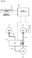
- the clutch hydraulic system for a vehicle of the first embodiment comprises a mechanical oil pump 17, an electric oil pump 18, a forward clutch 14 (clutch), a control valve unit 19, and a CVT controller 20 (clutch cooling control means).
- the mechanical oil pump 17 is an oil pump which is operated by the transmission input shaft 8 (rotary drive shaft) of the FF-hybrid drive system via a chain drive mechanism.
- This chain drive mechanism comprises a drive-side sprocket 21 provided on the transmission input shaft 5 side, a driven sprocket 23 provided to a pump shaft 22, and a chain 24 which is bridged between the two sprockets 21, 23, as illustrated in FIG. 1 .
- the electric oil pump 18 is an oil pump that is operated by an electric motor 25 independent of the mechanical oil pump 17. This electric oil pump 18 is disposed in a direction above the sheet in FIG. 1 , and therefore is not illustrated.
- the forward clutch 14 is provided to the drive system having a pump discharge pressure leading from the mechanical oil pump 17 as a hydraulic power source, and carried out a full engagement operation / slip engagement operation / disengagement operation via the control oil pressure from the control valve unit 19.
- the clutch is also one that is cooled by the hydraulic oil that is discharged from the electric oil pump 18.
- the control valve unit 19 regulates the pump discharge pressure leading from the mechanical oil pump 17 to a line pressure by a regulator valve, and creates an engagement/disengagement oil pressure and lubricating oil pressure to the forward clutch 14 with the line pressure as the source pressure.
- the control valve unit 19 also creates control oil pressure to the dry multi-plate clutch 4, control oil pressure to the reverse brake 13, control oil pressure to the primary pulley 15, and control oil pressure to an unillustrated secondary pulley.
- the main pump oil passage 26 leading from the mechanical oil pump 17 is connected to the control valve unit 19, as illustrated in FIG. 2 .
- the sub-pump oil passage 27 leading from the electric oil pump 18 is connected to a forward clutch oil passage 29 (clutch oil passage) into which an oil passage outlet 29a opens at an inside location closer to the clutch rotational axis CL than the clutch oil chamber 28 of the forward clutch 14, as illustrated in FIG. 1 .
- This sub-pump oil passage 27 is connected to an output oil passage 30 leading from the control valve unit 19, and the forward clutch oil passage 29 is connected on the downstream side of the connection position of the two oil passages of the sub-pump oil passage 27 and the output oil passage 30, as illustrated in FIG. 2 .
- the forward clutch oil passage 29 is formed on a fixing plate member 31 as an L-shaped plate member comprising a radial plate portion 31a that is disposed in a side position of the forward clutch 14, and an axial extension portion 31b that enters an interior region of the forward clutch 14 from the clutch rotational axis CL side end of the radial plate portion 31 a, as illustrated in FIG. 1 .
- This fixing plate member 31 is fixed to the transmission case, and maintains the fixed state regardless of the rotation of the transmission input shaft 8 and the forward clutch 14 of the FF-hybrid drive system.
- the forward clutch oil passage 29 is formed on the fixing plate member 31 and comprises a first radial oil passage portion 29b to which the sub-pump oil passage 27 is connected, an axial oil passage portion 29c extending in the axial direction from the clutch rotational axis CL side end of the first radial oil passage portion 29b, and a second radial oil passage portion 29d extending from the axial oil passage portion 29c in the outer diameter direction, and into which an oil passage outlet 29a opens.
- 33 is a lubricating oil passage, and lubricating oil is ejected in the radial direction from an axial oil passage.
- the CVT controller 20 actuates the electric motor 25 of the electric oil pump 18, when the forward clutch temperature detected by a clutch temperature sensor 32 (clutch temperature detection means) is at a predetermined temperature or higher.
- Various hydraulic controls in the control valve unit 19 are also carried out based on control commands from the CVT controller 20.
- FIG. 3 illustrates the flow of a hydraulic power source control process, which is carried out in the CVT controller 20 of the clutch hydraulic system for a vehicle of the first embodiment.
- This process is carried out repeatedly at predetermined time intervals.
- step S1 the temperature of the forward clutch 14 is detected by the clutch temperature sensor 32, and the process proceeds to step S2.
- step S2 following the clutch temperature detection in step S1, a determination is made as to whether or not the forward clutch temperature is at a predetermined temperature or higher. In the case of YES (forward clutch temperature ⁇ predetermined temperature) the process proceeds to step S3, and in the case of NO (forward clutch temperature ⁇ predetermined temperature) the process proceeds to step S4.
- the "predetermined temperature” is set to a temperature threshold at which the temperature of the forward clutch 14 must be kept from rising to a temperature at which clutch deterioration progresses by way of an oil cooling effect, for example in a state in which the forward clutch 14 is generating heat due to frictional heat during slip engagement.
- step S3 following the determination in step S2 that the forward clutch temperature ⁇ predetermined temperature, the electric motor 25 of the electric oil pump 18 is actuated, and the process proceeds to RETURN.
- the actuation of the electric motor 25 is performed by an output of a motor operation command which ensures the cooling oil amount of at least the forward clutch 14 in the electric oil pump 18.
- the motor operation command may be a fixed command value, or a variable command value which takes into consideration the temperature rise change, etc., of the forward clutch 14.
- step S4 following the determination in step S2 that the forward clutch temperature ⁇ predetermined temperature, the electric motor 25 of the electric oil pump 18 is stopped, and the process proceeds to RETURN.
- the present application is an invention relating to a hydraulic system of a second clutch CL2, in particular to the cooling of the second clutch CL2, provided to an FF-hybrid drive system (one-motor two-clutch).
- This FF-hybrid drive system is not equipped with a torque converter having a rotational difference absorption function, but instead is provided with a dry multi-plate clutch (corresponding to the first clutch CL1), as a starting element.
- the rotational difference between the high input rotational frequency (engine + motor) and the low axle rotational frequency is filled by slip engagement in which the clutch is allowed to slip in a half-clutch state.
- the second clutch CL2 which is a wet clutch, is mainly responsible for the slip engagement.
- the mechanical oil pump is driven by the rotation of the transmission input shaft, but the rotation does not reach a very high speed in a situation such as starting on a hill, so the amount of pump oil is limited, thus creating a durability problem for the second clutch CL2.
- the second clutch CL2 generates heat due to slippage, so cooling by applying oil is desired. Therefore, in order to solve the contradicting problem that the oil quantity cannot be secured but cooling the second clutch CL2 with oil is desired, a measure was taken to supplement the amount of oil by providing an electric oil pump.
- a Comparative Example shall be that of a clutch hydraulic system for a vehicle configured by merging a main pump oil passage leading from a mechanical oil pump (MOP) and a sub-pump oil passage leading from an electric oil pump (EOP), which is then connected to a control valve unit (C/V) via a common oil passage ( FIG. 4 ).
- MOP mechanical oil pump
- EOP electric oil pump
- a check valve needs to be disposed in each pump oil passage as a backflow prevention mechanism, in order to prevent oil from flowing back into the other pump, while one pump among the mechanical oil pump (MOP) and the electric oil pump (EOP) is in operation, as illustrated in FIG. 4 .
- the main pump oil passage 26 leading from the mechanical oil pump 17 is connected to the control valve unit 19.
- a sub-pump oil passage 27 leading from the electric oil pump 18 is connected to a forward clutch oil passage 29 into which an oil passage outlet 29a opens at an inside location closer to the clutch rotational axis CL than the clutch oil chamber 28 of the forward clutch 14.
- the sub-pump oil passage 27 leading from the electric oil pump 18 is connected to the output oil passage 30 leading from the control valve unit 19, and the forward clutch oil passage 29 is connected on the downstream side of the connection position of the two oil passages 27, 30 ( FIG. 2 ).
- the slip engagement pressure is outputted from the output oil passage 30 by the operation of the mechanical oil pump 17
- the slip engagement pressure is lower than the pump discharge pressure. Then, a negative pressure suction force due to the centrifugal pump effect operates in the forward clutch oil passage 29.
- the forward clutch oil passage 29 is formed on a fixing plate member 31 having an L-shaped cross-section, comprising a radial plate portion 31 a disposed in a side position of the forward clutch 14, and an axial extension portion 31b, which enters an interior region of the forward clutch 14 from the clutch rotational axis CL side end of the radial plate portion 31a ( FIG. 1 ).
- the forward clutch oil passage 29 can be formed easily, even if the electric oil pump 18 is positioned at a location away from the clutch rotational axis CL.
- the plate member on which is formed the forward clutch oil passage 29 is a fixing plate member 31 that maintains the fixed state regardless of the rotation of the drive system.
- the centrifugal pump effect acts on the oil which flows inside the forward clutch oil passage 29, thus preventing oil from flowing in a direction toward the clutch rotational axis CL.
- step S1 -> step S2 -> step S4 in the flowchart of FIG. 3 is repeated. That is, the electric oil pump 18 is placed in a stopped state in step S4.
- step S1 -> step S2 -> step S3 in the flowchart of FIG. 3 is repeated. That is, the electric oil pump 18 is placed in an activated state in step S3.
- a configuration is implemented to carry out a control operation to actuate the electric motor 25 of the electric oil pump 18, when the temperature of the forward clutch 14 is at a predetermined temperature or higher.
- the electric oil pump 18 is reduced in size by using the discharge oil only for cooling the forward clutch 14.
- the electric oil pump may also be used for controlling the clutch hydraulic pressure instead of the mechanical oil pump.
- the clutch hydraulic system for a vehicle of the present invention is applied to an FF-hybrid drive system.
- the clutch hydraulic system for a vehicle of the present invention may also be applied to an FR-hybrid drive system or an engine drive system and the like.
- the invention may be applied to any clutch hydraulic system for a vehicle equipped with two oil pumps as the hydraulic power source.
Landscapes
- Engineering & Computer Science (AREA)
- General Engineering & Computer Science (AREA)
- Mechanical Engineering (AREA)
- Physics & Mathematics (AREA)
- Fluid Mechanics (AREA)
- Hydraulic Clutches, Magnetic Clutches, Fluid Clutches, And Fluid Joints (AREA)
- Control Of Transmission Device (AREA)
Abstract
Description
- The present invention relates to a clutch hydraulic system for a vehicle equipped with two oil pumps, a mechanical oil pump and an electric oil pump, as a hydraulic power source.
- Conventionally, a clutch hydraulic system for a vehicle in which a main pump oil passage and a sub-pump oil passage are merged and connected to a control valve unit via a common oil passage is known (refer to, for example, Patent Document 1).
- Patent Document 1: Japanese Laid Open Patent Application No.
2012-82951 - However, a conventional clutch hydraulic system for a vehicle is configured so that a main pump oil passage and a sub-pump oil passage are merged and connected to a control valve unit via a common oil passage. Consequently, there is a problem in that a check valve needs to be disposed in each pump oil passage as a backflow prevention mechanism for preventing oil from flowing back into the other pump, while one pump among a mechanical oil pump and an electric oil pump is in operation.
- In view of the problem described above, an object of the present invention is to provide a clutch hydraulic system for a vehicle capable of eliminating the need to provide a backflow prevention mechanism, when installing two oil pumps as a hydraulic power source.
- In order to achieve the object above, the present invention comprises a mechanical oil pump, an electric oil pump, a clutch, and a control valve unit.
- In this clutch hydraulic system for a vehicle, a main pump oil passage leading from the mechanical oil pump is connected to the control valve unit.
- A sub-pump oil passage leading from the electric oil pump is connected to a clutch oil passage into which an oil passage outlet opens at an inside location closer to the clutch rotational axis than the clutch oil chamber of the clutch.
- Therefore, a main pump oil passage leading from the mechanical oil pump is connected to the control valve unit. On the other hand, a sub-pump oil passage leading from the electric oil pump is connected to a clutch oil passage into which an oil passage outlet opens at an inside location closer to the clutch rotational axis than the clutch oil chamber of the clutch.
- In other words, when a main pump oil passage and a sub-pump oil passage are merged and connected to a control valve unit via a common oil passage, a backflow prevention mechanism is installed in each pump oil passage.
- In contrast, by connecting only the main pump oil passage to the control valve unit, and connecting the sub-pump oil passage directly to the clutch oil passage, installing a backflow prevention mechanism becomes unnecessary. The reason for this is as follows: by having an oil passage outlet of the clutch oil passage opened at an inside location closer to the clutch rotational axis than the clutch oil chamber of the clutch, a rotating clutch is positioned on the outer diameter side of the outlet of the sub-pump oil passage. Accordingly, the oil passage outlet of the clutch oil passage is placed under a negative pressure due to the centrifugal pump effect caused by the rotation of the clutch, and a suction force for suctioning oil from the clutch oil passage acts to prevent backflow to the pump side.
- As a result, the need to provide a backflow prevention mechanism can be eliminated, while installing two oil pumps as a hydraulic power source.
-
- [
FIG. 1 ] is a schematic diagram illustrating an FF-hybrid drive system to which is applied the clutch hydraulic system for a vehicle in accordance with a first embodiment. - [
FIG. 2 ] is a system configuration diagram illustrating the clutch hydraulic system for the vehicle of the first embodiment. - [
FIG. 3 ] is a flowchart illustrating a hydraulic power source control process which is executed in a CVT controller of the clutch hydraulic system for the vehicle of the first embodiment. - [
FIG. 4 ] is a system configuration diagram illustrating the clutch hydraulic system for a vehicle of a comparative example. - [
FIG. 5 ] is an explanatory diagram of the oil supply operation, illustrating an operation for supplying oil to a forward clutch in an inner diameter direction toward a clutch rotational axis, in the clutch hydraulic system for the vehicle. - [
FIG. 6 ] is an explanatory diagram of the oil supply operation, illustrating an operation for supplying oil to a forward clutch in an outer diameter direction away from the clutch rotational axis, in the clutch hydraulic system for the vehicle of the first embodiment. - Preferred embodiments for realizing the clutch hydraulic system for a vehicle of the present invention are explained below based on the first embodiment illustrated in the drawings.
- The configuration is described first.
- The "overall structure," "configuration of the clutch hydraulic system for a vehicle," and the "configuration of the hydraulic power source control" will be described separately with regard to the configuration of the clutch hydraulic system for a vehicle of the first embodiment.
-
FIG. 1 illustrates an FF-hybrid drive system to which is applied the clutch hydraulic system for a vehicle. The overall structure of the FF-hybrid drive system is described below, based onFIG. 1 . - The FF-hybrid drive system is configured from an unillustrated engine, a motor & clutch unit M&C/U, and a continuously variable transmission unit CVT/U, as illustrated in
FIG. 1 . The system further comprises a unit case 1, anengine connecting shaft 2, aclutch hub 3, a drymulti-plate clutch 4, a rotor &clutch drum 5, a motor/generator 6, arotor shaft 7, atransmission input shaft 8, and a clutchhydraulic actuator 9. - This FF-hybrid drive system has a configuration known as one-motor (motor/generator 6) two-clutch (a first clutch CL1, a second clutch CL2), in which an "electric vehicle mode (EV mode)" or a "hybrid vehicle mode (HEV mode)" can be selected as the drive mode. That is, by disengaging the dry multi-plate clutch 4 (corresponding to the first clutch CL1), the "EV mode" is selected and the motor/
generator 6 and thetransmission input shaft 8 are connected via the rotor &clutch drum 5 and therotor shaft 7. By engaging the dry multi-plate clutch 4 (corresponding to first clutch CL1), the "HEV mode" is selected and an engine, not shown in the drawings, and the motor/generator 6 are connected via the drymulti-plate clutch 4. - The motor & clutch unit M&C/U comprises, housed in the unit case 1 and sandwiching the rotor &
clutch drum 5, a dry multi-plate clutch 4 disposed on the engine side, a motor/generator 6 disposed on the drum outer perimeter side, and a clutchhydraulic actuator 9 disposed on the transmission side. That is, the rotor &clutch drum 5 have the function of partitioning the space inside the unit case 1 into three spaces: a first dry space for disposing the drymulti-plate clutch 4, a second dry space for disposing the motor/generator 6, and a wet space for disposing the clutchhydraulic actuator 9. - The dry
multi-plate clutch 4 is intended for connecting/disconnecting the drive power transmission leading from an unillustrated engine. This drymulti-plate clutch 4 is a normally open clutch configured by alternately arranging adrive plate 41, which is splined to theclutch hub 3, and a driven plate 42, which is splined to the rotor &clutch drum 5. - The motor/
generator 6 is configured by a synchronous AC motor, and is disposed on the outer perimeter position of the rotor &clutch drum 5. This motor/generator 6 comprises arotor 61, which is supported and fixed to the outer perimeter surface of the rotor &clutch drum 5, and apermanent magnet 62, which is disposed so as to be embedded in therotor 61. The motor/generator further comprises a stator 63, which is fixed to the unit case 1 and disposed relative to therotor 61 so as to have an air gap therebetween, and astator coil 64 which is wound on the stator 63. - The clutch
hydraulic actuator 9 hydraulically controls the engagement/disengagement of the drymulti-plate clutch 4. This clutchhydraulic actuator 9 comprises apiston 91, a needle bearing 92, apiston arm 93, which extends through the rotor &clutch drum 5 in a plurality of locations, a return spring 94, an arm press-plate 95, and a bellows elastic support member 96. - The continuously variable transmission unit CVT/U is coupled to the motor & clutch unit M&C/U, and comprises a forward/reverse switching mechanism 10 and a V-belt type continuously variable transmission mechanism 11. The forward/reverse switching mechanism 10 comprises a
planetary gear 12, a reverse brake 13 (corresponding to the second clutch CL2 in the R-range), and a forward clutch 14 (corresponding to the second clutch CL2 in the D-range); the mechanism reverses the direction and decelerates the rotation leading from thetransmission input shaft 8 and transmits same to aprimary pulley 15 by engaging thereverse brake 13. Then, the mechanism directly connects thetransmission input shaft 8 and theprimary pulley 15 by engaging theforward clutch 14. The V-belt type continuously variable transmission mechanism 11 achieves a stepless transmission ratio by bridging a V-belt between theprimary pulley 15 and a secondary pulley, not shown in the drawings, and by changing the belt contact diameter by controlling the primary pulley pressure and the secondary pulley pressure. - In
FIG. 1 , 16 is a resolver configured by a rotor and a stator for detecting the rotational position of the motor/generator 6. -
Figure 2 illustrates the clutch hydraulic system for a vehicle of the first embodiment. The configuration of the clutch hydraulic system for a vehicle will be described below, based onFIG. 1 andFIG. 2 . - The clutch hydraulic system for a vehicle of the first embodiment comprises a
mechanical oil pump 17, anelectric oil pump 18, a forward clutch 14 (clutch), acontrol valve unit 19, and a CVT controller 20 (clutch cooling control means). - The
mechanical oil pump 17 is an oil pump which is operated by the transmission input shaft 8 (rotary drive shaft) of the FF-hybrid drive system via a chain drive mechanism. This chain drive mechanism comprises a drive-side sprocket 21 provided on thetransmission input shaft 5 side, a drivensprocket 23 provided to apump shaft 22, and achain 24 which is bridged between the twosprockets FIG. 1 . - The
electric oil pump 18 is an oil pump that is operated by anelectric motor 25 independent of themechanical oil pump 17. Thiselectric oil pump 18 is disposed in a direction above the sheet inFIG. 1 , and therefore is not illustrated. - The
forward clutch 14 is provided to the drive system having a pump discharge pressure leading from themechanical oil pump 17 as a hydraulic power source, and carried out a full engagement operation / slip engagement operation / disengagement operation via the control oil pressure from thecontrol valve unit 19. The clutch is also one that is cooled by the hydraulic oil that is discharged from theelectric oil pump 18. - The
control valve unit 19 regulates the pump discharge pressure leading from themechanical oil pump 17 to a line pressure by a regulator valve, and creates an engagement/disengagement oil pressure and lubricating oil pressure to the forward clutch 14 with the line pressure as the source pressure. In addition to the control oil pressure to theforward clutch 14, thecontrol valve unit 19 also creates control oil pressure to the drymulti-plate clutch 4, control oil pressure to thereverse brake 13, control oil pressure to theprimary pulley 15, and control oil pressure to an unillustrated secondary pulley. - The main
pump oil passage 26 leading from themechanical oil pump 17 is connected to thecontrol valve unit 19, as illustrated inFIG. 2 . - The
sub-pump oil passage 27 leading from theelectric oil pump 18 is connected to a forward clutch oil passage 29 (clutch oil passage) into which anoil passage outlet 29a opens at an inside location closer to the clutch rotational axis CL than the clutch oil chamber 28 of theforward clutch 14, as illustrated inFIG. 1 . Thissub-pump oil passage 27 is connected to anoutput oil passage 30 leading from thecontrol valve unit 19, and the forwardclutch oil passage 29 is connected on the downstream side of the connection position of the two oil passages of thesub-pump oil passage 27 and theoutput oil passage 30, as illustrated inFIG. 2 . - The forward
clutch oil passage 29 is formed on a fixingplate member 31 as an L-shaped plate member comprising a radial plate portion 31a that is disposed in a side position of theforward clutch 14, and anaxial extension portion 31b that enters an interior region of the forward clutch 14 from the clutch rotational axis CL side end of the radial plate portion 31 a, as illustrated inFIG. 1 . This fixingplate member 31 is fixed to the transmission case, and maintains the fixed state regardless of the rotation of thetransmission input shaft 8 and theforward clutch 14 of the FF-hybrid drive system. - The forward
clutch oil passage 29 is formed on the fixingplate member 31 and comprises a first radialoil passage portion 29b to which thesub-pump oil passage 27 is connected, an axialoil passage portion 29c extending in the axial direction from the clutch rotational axis CL side end of the first radialoil passage portion 29b, and a second radialoil passage portion 29d extending from the axialoil passage portion 29c in the outer diameter direction, and into which anoil passage outlet 29a opens. - In
FIG. 1 andFIG. 2 , 33 is a lubricating oil passage, and lubricating oil is ejected in the radial direction from an axial oil passage. - The
CVT controller 20 actuates theelectric motor 25 of theelectric oil pump 18, when the forward clutch temperature detected by a clutch temperature sensor 32 (clutch temperature detection means) is at a predetermined temperature or higher. Various hydraulic controls in thecontrol valve unit 19 are also carried out based on control commands from theCVT controller 20. -
FIG. 3 illustrates the flow of a hydraulic power source control process, which is carried out in theCVT controller 20 of the clutch hydraulic system for a vehicle of the first embodiment. Each of the steps inFIG. 3 , which represent the configuration of the hydraulic power source control, will be described below. This process is carried out repeatedly at predetermined time intervals. - In step S1, the temperature of the
forward clutch 14 is detected by theclutch temperature sensor 32, and the process proceeds to step S2. - In step S2, following the clutch temperature detection in step S1, a determination is made as to whether or not the forward clutch temperature is at a predetermined temperature or higher. In the case of YES (forward clutch temperature ≥ predetermined temperature) the process proceeds to step S3, and in the case of NO (forward clutch temperature < predetermined temperature) the process proceeds to step S4.
- Here, the "predetermined temperature" is set to a temperature threshold at which the temperature of the forward clutch 14 must be kept from rising to a temperature at which clutch deterioration progresses by way of an oil cooling effect, for example in a state in which the
forward clutch 14 is generating heat due to frictional heat during slip engagement. - In step S3, following the determination in step S2 that the forward clutch temperature ≥ predetermined temperature, the
electric motor 25 of theelectric oil pump 18 is actuated, and the process proceeds to RETURN. - Here, the actuation of the
electric motor 25 is performed by an output of a motor operation command which ensures the cooling oil amount of at least the forward clutch 14 in theelectric oil pump 18. The motor operation command may be a fixed command value, or a variable command value which takes into consideration the temperature rise change, etc., of theforward clutch 14. - In step S4, following the determination in step S2 that the forward clutch temperature < predetermined temperature, the
electric motor 25 of theelectric oil pump 18 is stopped, and the process proceeds to RETURN. - Next, the effects are described.
- The "technical background," "problems of the comparative examples," "reduction effect of the backflow prevention mechanism," and "oil cooling effect of the forward clutch" will be separately described regarding the effects of the clutch hydraulic system for a vehicle of the first embodiment.
- The present application is an invention relating to a hydraulic system of a second clutch CL2, in particular to the cooling of the second clutch CL2, provided to an FF-hybrid drive system (one-motor two-clutch). This FF-hybrid drive system is not equipped with a torque converter having a rotational difference absorption function, but instead is provided with a dry multi-plate clutch (corresponding to the first clutch CL1), as a starting element. Accordingly, when desiring to increase the axle torque while substantially fixing the rotational frequency of the axle, such as when starting on a slope, in order to obtain the required torque, the rotational difference between the high input rotational frequency (engine + motor) and the low axle rotational frequency is filled by slip engagement in which the clutch is allowed to slip in a half-clutch state.
- Here, since a dry multi-plate clutch is used as the first clutch CL1, the half-clutch state cannot be maintained for a long time. Consequently, the second clutch CL2, which is a wet clutch, is mainly responsible for the slip engagement.
- In addition, the mechanical oil pump is driven by the rotation of the transmission input shaft, but the rotation does not reach a very high speed in a situation such as starting on a hill, so the amount of pump oil is limited, thus creating a durability problem for the second clutch CL2. On the other hand, the second clutch CL2 generates heat due to slippage, so cooling by applying oil is desired. Therefore, in order to solve the contradicting problem that the oil quantity cannot be secured but cooling the second clutch CL2 with oil is desired, a measure was taken to supplement the amount of oil by providing an electric oil pump.
- In contrast, in the case where the "EV mode" is often used, and when it is desirable to ensure complete provision of the hydraulic pressure, even if the transmission input shaft has stopped, a mechanical oil pump and a large electric oil pump are provided as a countermeasure. However, in the case where the "EV mode" is used in a limited manner, basically, since the engine is operating, the rotation of the mechanical oil pump also reaches a relatively high speed, so the required oil quantity can be quickly secured. In addition, besides the above, even if the engine is stopped when the vehicle is stopped, the oil quantity can be ensured by the motor maintaining the equivalent of idling rotation; therefore, the need of the electric oil pump becomes less than that of a case in which the "EV mode" is often used.
- However, in order to solve the problem of wanting to cool the second clutch CL2 with oil in a situation in which the amount of oil cannot be secured such as during starting on a hill, the amount of oil from the mechanical oil pump is insufficient, thus using an electric oil pump is essential. In this case, when taking care to ensure that the amount of cooling oil for the second clutch CL2 is sufficient, the cost disadvantage can be avoided by using a small electric oil pump. Furthermore, the desire to reduce costs by eliminating check valves from the hydraulic circuit is the technical background of the present invention.
- A Comparative Example shall be that of a clutch hydraulic system for a vehicle configured by merging a main pump oil passage leading from a mechanical oil pump (MOP) and a sub-pump oil passage leading from an electric oil pump (EOP), which is then connected to a control valve unit (C/V) via a common oil passage (
FIG. 4 ). - In the case of this Comparative Example, a check valve needs to be disposed in each pump oil passage as a backflow prevention mechanism, in order to prevent oil from flowing back into the other pump, while one pump among the mechanical oil pump (MOP) and the electric oil pump (EOP) is in operation, as illustrated in
FIG. 4 . - That is, while the mechanical oil pump can generate high hydraulic pressure, the rotation thereof at the time of start is not very high, and the hydraulic pressure (oil amount) that is supplied to the clutch is limited by a regulator valve or the like and thus is low; therefore, the hydraulic pressure on the mechanical oil pump circuit side is by no means high. Consequently, if the electric oil pump is actuated, there is the risk that hydraulic pressure from the electric oil pump will exceed the hydraulic pressure from the mechanical oil pump thus causing a backflow. Therefore, check valves are provided so that when the hydraulic pressure of the electric oil pump exceeds that of the mechanical oil pump, the supply is switched from the mechanical oil pump circuit to the electric oil pump, in order to prevent insufficient cooling liquid as well as fluctuations in the hydraulic pressure of the mechanical oil pump hydraulic circuit that are caused by backflow.
- In the case of the clutch hydraulic system for a vehicle of the Comparative Example, since the configuration is one in which a check valve is disposed in each of the pump oil passages as a backflow prevention mechanism, there are the following additional problems.
- (a) Since the check valve becomes a piping resistance, the structure (size, capacity) of the mechanical oil pump and the electric oil pump must be increased.
- (b) Depending on the balance state of the oil flow, chattering is generated in the check valves. For example, if the electric oil pump is operated in a state in which there is residual hydraulic pressure from the mechanical oil pump, pressure will achieve balance near the valve opening pressure of the check valve, generating oil vibration due to the opening and closing.
- As described above, eliminating check valves installed in the respective pump oil passages of the mechanical oil pump and the electric oil pump is preferable from the perspective of increasing the cost advantage. The reduction effect of the backflow prevention mechanism, which reflects the above preference, is described below, based on
FIG. 5 and FIG. 6 . - In the first embodiment, the main
pump oil passage 26 leading from themechanical oil pump 17 is connected to thecontrol valve unit 19. On the other hand, asub-pump oil passage 27 leading from theelectric oil pump 18 is connected to a forwardclutch oil passage 29 into which anoil passage outlet 29a opens at an inside location closer to the clutch rotational axis CL than the clutch oil chamber 28 of theforward clutch 14. - That is, by connecting only the main
pump oil passage 26 to thecontrol valve unit 19, and connecting thesub-pump oil passage 27 directly to the forwardclutch oil passage 29, it becomes unnecessary to install a backflow prevention mechanism. The reasons are explained. - First, if oil is supplied to a rotating member such as the forward clutch in the inner diameter direction toward the clutch rotational axis CL, a force in the backflow direction, which is the opposite direction of the oil supply direction, acts on the forward clutch oil passage, due to the centrifugal pump effect from the axial center portion of the rotating member, as illustrated in
FIG. 5 . - In contrast, in the first embodiment, by having an
oil passage outlet 29a of theclutch oil passage 29 open at an inside location closer to the clutch rotational axis CL than the clutch oil chamber 28 of theforward clutch 14, a rotating forward clutch 14 is positioned on the outer diameter side of the outlet of thesub-pump oil passage 27. In this manner, if oil is supplied to theforward clutch 14, which is a rotating member, in the outer diameter direction away from the clutch rotational axis CL2, theoil passage outlet 29a of the forwardclutch oil passage 29 is placed under a negative pressure due to the centrifugal pump effect caused by the rotation of theforward clutch 14, and a suction force for the forward clutch 14 to suction oil from the forwardclutch oil passage 29 acts so as to prevent backflow to the pump side, as illustrated inFIG. 6 . - Normally, if all that is required is to apply cooling oil to the clutch, injection (applying oil) using the pumping force of the pump is simple, easy, and allows disposing an oil passage anywhere. However, when limited to the cooling portion of the
forward clutch 14, an arrangement is made so that the centrifugal pump effect is caused by the rotation of theforward clutch 14. That is, as long as theforward clutch 14 is rotating, a negative pressure state exists around theforward clutch 14; therefore, the mode is one in which the axial portion acts as an oil reservoir, and oil is suctioned from the forwardclutch oil passage 29. - As a result, the need to provide a backflow prevention mechanism can be eliminated, while installing the
mechanical oil pump 17 and theelectric oil pump 18 as a hydraulic power source. - In the first embodiment, the
sub-pump oil passage 27 leading from theelectric oil pump 18 is connected to theoutput oil passage 30 leading from thecontrol valve unit 19, and the forwardclutch oil passage 29 is connected on the downstream side of the connection position of the twooil passages 27, 30 (FIG. 2 ). - For example, in the case where the slip engagement pressure is outputted from the
output oil passage 30 by the operation of themechanical oil pump 17, the slip engagement pressure is lower than the pump discharge pressure. Then, a negative pressure suction force due to the centrifugal pump effect operates in the forwardclutch oil passage 29. - Therefore, a flow toward the outlet side of the forward
clutch oil passage 29 can be ensured by preventing backflow to theelectric oil pump 18 side, whether theelectric oil pump 18 is being operated or is stopped. - In the first embodiment, the forward
clutch oil passage 29 is formed on a fixingplate member 31 having an L-shaped cross-section, comprising a radial plate portion 31 a disposed in a side position of theforward clutch 14, and anaxial extension portion 31b, which enters an interior region of the forward clutch 14 from the clutch rotational axis CL side end of the radial plate portion 31a (FIG. 1 ). - In other words, in the case of opening an
oil passage outlet 29a of the forwardclutch oil passage 29 at an inside location of the clutch oil chamber 28, if the forwardclutch oil passage 29 is formed on the clutch rotational axis CL side, the oil passage structure of the forwardclutch oil passage 29 is simplified. However, if the forwardclutch oil passage 29 is formed at a location way from the clutch rotational axis CL, the oil passage structure of the forwardclutch oil passage 29 into which anoil passage outlet 29a opens at an inside location of the clutch oil chamber 28 becomes complex. - In contrast, by forming the forward
clutch oil passage 29 on a fixingplate member 31 with an L-shaped cross-section, the forwardclutch oil passage 29 can be formed easily, even if theelectric oil pump 18 is positioned at a location away from the clutch rotational axis CL. - In the first embodiment, the plate member on which is formed the forward
clutch oil passage 29 is a fixingplate member 31 that maintains the fixed state regardless of the rotation of the drive system. - For example, if the forward
clutch oil passage 29 is formed on a rotating member, the centrifugal pump effect acts on the oil which flows inside the forwardclutch oil passage 29, thus preventing oil from flowing in a direction toward the clutch rotational axis CL. - In contrast, by forming the forward
clutch oil passage 29 on the fixingplate member 31, the centrifugal pump effect does not act on the oil that flows inside the forwardclutch oil passage 29; therefore, oil can flow smoothly in a direction toward the clutch rotational axis CL. - For example, when traveling forward, the
forward clutch 14 is in a full engagement state, and the clutch temperature is low, the flow: step S1 -> step S2 -> step S4 in the flowchart ofFIG. 3 is repeated. That is, theelectric oil pump 18 is placed in a stopped state in step S4. - On the other hand, when starting, etc., the
forward clutch 14 is in a slip-engaged state, and the clutch temperature is high due to the generation of frictional heat, the flow: step S1 -> step S2 -> step S3 in the flowchart ofFIG. 3 is repeated. That is, theelectric oil pump 18 is placed in an activated state in step S3. - In this manner, in the first embodiment, a configuration is implemented to carry out a control operation to actuate the
electric motor 25 of theelectric oil pump 18, when the temperature of theforward clutch 14 is at a predetermined temperature or higher. - In other words, by carrying out a control operation to set the application of the
electric oil pump 18 for the purpose of cooling theforward clutch 14, a small pump having the capacity to ensure the amount of cooling oil can be used as theelectric oil pump 18. In addition, since the system configuration omits check valves, it is cost-effective. - The effects listed below can be obtained by means of the clutch hydraulic system for a vehicle of the first embodiment.
- (1) In a clutch hydraulic system for a vehicle comprising: a
mechanical oil pump 17 actuated by a rotary drive shaft (transmission input shaft 8) of a drive system (FF-hybrid drive system);
anelectric oil pump 18 actuated by anelectric oil pump 25 independent of themechanical oil pump 17;
a clutch (forward clutch 14) provided to the drive system (FF-hybrid drive system), which operates themechanical oil pump 17 and theelectric oil pump 18 as a hydraulic power source; and
acontrol valve unit 19 for providing engagement oil pressure and lubricating oil pressure to the clutch (forward clutch 14) based on a pump discharge pressure from the hydraulic power source;
a mainpump oil passage 26 leading from themechanical oil pump 17 is connected to thecontrol valve unit 19, and
asub-pump oil passage 27 leading from theelectric oil pump 18 is connected to a clutch oil passage (forward clutch oil passage 29) into which anoil passage outlet 29a opens at an inside location closer to a clutch rotational axis CL than a clutch oil chamber 28 of the clutch (forward clutch 14) (FIG. 2 ).
Accordingly, the need to provide a backflow prevention mechanism can be eliminated, when installing two oil pumps (mechanical oil pump 17, electric oil pump 18) as a hydraulic power source. - (2) A
sub-pump oil passage 27 leading from theelectric oil pump 18 is connected to anoutput oil passage 30 leading from thecontrol valve unit 19, and the clutch oil passage (forward clutch oil passage 29) is connected on the downstream side of the connection position of the twooil passages 27, 30 (FIG. 2 ).
Accordingly, in addition to the effect of (1), a flow toward the outlet side of the clutch oil passage (forward clutch oil passage 29) can be ensured by preventing backflow to theelectric oil pump 18 side, whether theelectric oil pump 18 is being operated or is stopped. - (3) The clutch oil passage (forward clutch oil passage 29) is formed on an L-shaped plate member (fixing plate member 31) comprising a radial plate portion 31 a disposed in a side position of the clutch (forward clutch 14), and an
axial extension portion 31b, which enters an interior region of the clutch (forward clutch 14) from the clutch rotational axis CL side end of the radial plate portion 31a (FIG. 1 ).
Accordingly, in addition to the effect of (1) or (2), the clutch oil passage (forward clutch oil passage 29) can be formed easily, even if theelectric oil pump 18 is positioned at a location away from the clutch rotational axis CL. - (4) The plate member is a fixing
plate member 31 that maintains the fixed state regardless of the rotation of the drive system (FIG. 1 ).
Accordingly, in addition to the effect of (3), the centrifugal pump effect does not act on the oil that flows inside the clutch oil passage (forward clutch oil passage 29); therefore, oil can flow smoothly in a direction toward the clutch rotational axis CL. - (5) The embodiment comprises a clutch temperature detection means (clutch temperature sensor 32) for detecting a temperature of the clutch (forward clutch 14); and
a clutch cooling control means (CVT controller 20) for actuating anelectric motor 25 of theelectric oil pump 18, when the temperature of the clutch (forward clutch 14) is at a predetermined temperature or higher (FIG. 2 ). - Accordingly, in addition to the effects of (1) - (4), while achieving a system which is cost-effective by reducing the size of the
electric oil pump 18 and omitting check valves, deterioration in the durability of the clutch (forward clutch 14) caused by an increase in temperature can be prevented, by oil-cooling the clutch (forward clutch 14) when generating heat. - The clutch hydraulic system for a vehicle of the present invention was described above based on the first embodiment, however specific configurations thereof are not limited to the first embodiment, and various modifications and additions to the design can be made without departing from the scope of the invention according to each claim in the Claims.
- In the first embodiment, an example was shown in which the
electric oil pump 18 is reduced in size by using the discharge oil only for cooling theforward clutch 14. However, the electric oil pump may also be used for controlling the clutch hydraulic pressure instead of the mechanical oil pump. - In the first embodiment, an example was shown in which the clutch hydraulic system for a vehicle of the present invention is applied to an FF-hybrid drive system. However, the clutch hydraulic system for a vehicle of the present invention may also be applied to an FR-hybrid drive system or an engine drive system and the like. In short, the invention may be applied to any clutch hydraulic system for a vehicle equipped with two oil pumps as the hydraulic power source.
- This application claims right of priority based on Japanese Patent Application No.
2013-138601
Claims (5)
- A clutch hydraulic system for a vehicle, comprising:a mechanical oil pump actuated by a rotary drive shaft of a drive system;an electric oil pump actuated by an electric motor independent of the mechanical oil pump;a clutch disposed in the drive system, which operates the mechanical oil pump and the electric oil pump as a hydraulic power source; anda control valve unit for providing engagement oil pressure and lubricating oil pressure to the clutch based on a pump discharge pressure from the hydraulic power source; whereina main pump oil passage leading from the mechanical oil pump is connected to the control valve unit; anda sub-pump oil passage leading from the electric oil pump is connected to a clutch oil passage into which an oil passage outlet opens at an inside location closer to a clutch rotational axis than a clutch oil chamber of the clutch.
- The clutch hydraulic system for a vehicle according to claim 1, wherein
the sub-pump oil passage leading from the electric oil pump is connected to an output oil passage leading from the control valve unit, and the clutch oil passage is connected on a downstream side of a connection position of the two oil passages. - The clutch hydraulic system for a vehicle according to claim 1 or 2, wherein
the clutch oil passage is formed on an L-shaped plate member comprises a radial plate portion disposed in a side position of the clutch, and an axial extension portion that enters an interior region of the clutch from a clutch rotational axis side end of the radial plate portion. - The clutch hydraulic system for a vehicle according to claim 3, wherein
the plate member on which is formed the clutch oil passage is a fixing plate member that maintains a fixed state regardless of the rotation of the drive system. - The clutch hydraulic system for a vehicle according to any one of claims 1 to 4, further comprising
a clutch temperature detection means for detecting a temperature of the clutch; and
a clutch cooling control means for actuating the electric motor of the electric oil pump, when a temperature of the clutch is at a predetermined temperature or higher.
Applications Claiming Priority (2)
| Application Number | Priority Date | Filing Date | Title |
|---|---|---|---|
| JP2013138601 | 2013-07-02 | ||
| PCT/JP2014/066161 WO2015001959A1 (en) | 2013-07-02 | 2014-06-18 | Clutch hydraulic system for vehicle |
Publications (3)
| Publication Number | Publication Date |
|---|---|
| EP3018387A1 true EP3018387A1 (en) | 2016-05-11 |
| EP3018387A4 EP3018387A4 (en) | 2016-10-19 |
| EP3018387B1 EP3018387B1 (en) | 2018-08-08 |
Family
ID=52143537
Family Applications (1)
| Application Number | Title | Priority Date | Filing Date |
|---|---|---|---|
| EP14819856.7A Not-in-force EP3018387B1 (en) | 2013-07-02 | 2014-06-18 | Clutch hydraulic system for vehicle |
Country Status (8)
| Country | Link |
|---|---|
| US (1) | US9869353B2 (en) |
| EP (1) | EP3018387B1 (en) |
| JP (1) | JP6020724B2 (en) |
| CN (1) | CN105358878B (en) |
| MX (1) | MX2015017920A (en) |
| MY (1) | MY175945A (en) |
| RU (1) | RU2670555C2 (en) |
| WO (1) | WO2015001959A1 (en) |
Families Citing this family (5)
| Publication number | Priority date | Publication date | Assignee | Title |
|---|---|---|---|---|
| CN106494387B (en) * | 2015-09-06 | 2020-03-17 | 德昌电机(深圳)有限公司 | Auxiliary oil pump system of gearbox and starting method |
| KR101886530B1 (en) * | 2016-12-12 | 2018-08-07 | 현대자동차주식회사 | Oil control system and method for dual clutch transmission |
| JP6733574B2 (en) * | 2017-02-20 | 2020-08-05 | トヨタ自動車株式会社 | Hydraulic control device for engagement mechanism |
| JP7209562B2 (en) * | 2019-03-19 | 2023-01-20 | ジヤトコ株式会社 | Vehicle drive system |
| DE102020209461A1 (en) * | 2020-07-28 | 2022-02-03 | Zf Friedrichshafen Ag | Torque transmission device for transmitting torque to a transmission of a vehicle that can be driven via a hybrid drive |
Family Cites Families (16)
| Publication number | Priority date | Publication date | Assignee | Title |
|---|---|---|---|---|
| JPS5922100B2 (en) | 1977-02-14 | 1984-05-24 | トヨタ自動車株式会社 | Automatic transmission hydraulic control device |
| US4856628A (en) * | 1987-11-17 | 1989-08-15 | Hino Jidosha Kogyo Kabushiki Kaisha | Automated mechanical transmission system for use in commercial vehicles |
| GB2380531B (en) * | 2000-02-15 | 2004-10-20 | Luk Lamellen & Kupplungsbau | Torque transfer device. |
| DE10143833B4 (en) * | 2001-09-07 | 2013-06-06 | Zf Friedrichshafen Ag | Coupling system in a drive train between a drive unit and a transmission |
| JP3691469B2 (en) * | 2002-08-07 | 2005-09-07 | 本田技研工業株式会社 | Hybrid vehicle hydraulic circuit |
| DE102004033439C5 (en) * | 2004-07-08 | 2009-02-26 | Getrag Driveline Systems Gmbh | Powertrain for a motor vehicle |
| EP1722121A1 (en) * | 2005-05-09 | 2006-11-15 | HOERBIGER Antriebstechnik GmbH | Hydraulic double clutch |
| JP4464984B2 (en) * | 2007-04-20 | 2010-05-19 | トヨタ自動車株式会社 | Vehicle oil supply device |
| JP2010281432A (en) * | 2009-06-08 | 2010-12-16 | Toyota Central R&D Labs Inc | Hydraulic transmission device for automatic transmission |
| DE102009037344A1 (en) * | 2009-08-14 | 2011-02-17 | Volkswagen Ag | Method for controlling the coolant supply and the lubricant supply of a clutch of a motor vehicle with an automatic transmission |
| EP2489896B1 (en) * | 2009-10-14 | 2019-06-12 | Nissan Motor Co., Ltd. | Vehicle control device |
| JP5533247B2 (en) * | 2010-05-20 | 2014-06-25 | 日産自動車株式会社 | Driving force transmission device |
| KR101154411B1 (en) | 2010-10-14 | 2012-06-15 | 기아자동차주식회사 | Hydraulic control system of automatic transmission for hybrid vehicle |
| JP2012192913A (en) * | 2011-02-28 | 2012-10-11 | Aisin Aw Co Ltd | Driving device for vehicle |
| KR101566725B1 (en) * | 2011-09-27 | 2015-11-09 | 현대자동차 주식회사 | Hydraulic clutch |
| DE102011089751B4 (en) * | 2011-12-23 | 2022-03-31 | Schaeffler Technologies AG & Co. KG | Wet multi-plate clutch |
-
2014
- 2014-06-18 MX MX2015017920A patent/MX2015017920A/en unknown
- 2014-06-18 MY MYPI2015704669A patent/MY175945A/en unknown
- 2014-06-18 US US14/896,674 patent/US9869353B2/en not_active Expired - Fee Related
- 2014-06-18 JP JP2015525131A patent/JP6020724B2/en not_active Expired - Fee Related
- 2014-06-18 CN CN201480038137.4A patent/CN105358878B/en not_active Expired - Fee Related
- 2014-06-18 WO PCT/JP2014/066161 patent/WO2015001959A1/en not_active Ceased
- 2014-06-18 RU RU2016103131A patent/RU2670555C2/en active
- 2014-06-18 EP EP14819856.7A patent/EP3018387B1/en not_active Not-in-force
Also Published As
| Publication number | Publication date |
|---|---|
| JPWO2015001959A1 (en) | 2017-02-23 |
| RU2016103131A3 (en) | 2018-04-02 |
| EP3018387A4 (en) | 2016-10-19 |
| CN105358878A (en) | 2016-02-24 |
| EP3018387B1 (en) | 2018-08-08 |
| US20160146270A1 (en) | 2016-05-26 |
| US9869353B2 (en) | 2018-01-16 |
| MX2015017920A (en) | 2016-04-29 |
| WO2015001959A1 (en) | 2015-01-08 |
| CN105358878B (en) | 2018-05-11 |
| MY175945A (en) | 2020-07-16 |
| RU2016103131A (en) | 2017-08-07 |
| JP6020724B2 (en) | 2016-11-02 |
| RU2670555C2 (en) | 2018-10-23 |
Similar Documents
| Publication | Publication Date | Title |
|---|---|---|
| JP6130860B2 (en) | Oil supply device | |
| JP5499998B2 (en) | Driving force transmission device | |
| US8308595B2 (en) | Hybrid drive device | |
| US8327986B2 (en) | Combined power transmission, start-up unit and drive system | |
| CN105190109B (en) | Oil feeding mechanism | |
| JP6089533B2 (en) | Clutch control device for clutch device for hybrid vehicle | |
| EP3018387B1 (en) | Clutch hydraulic system for vehicle | |
| JP5627577B2 (en) | Switchable clutch device in disk structure | |
| JP5445045B2 (en) | Hydraulic control device for automatic transmission | |
| CN102007324B (en) | Hydraulic control apparatus | |
| JP3704949B2 (en) | Hydraulic supply device | |
| EP2977650B1 (en) | Lubricant flowrate control device of automatic transmission, and lubricant flowrate control method | |
| EP2607648A1 (en) | Control system for vehicle | |
| WO2010106833A1 (en) | Control device for automatic transmission | |
| EP2767724A1 (en) | Drive power transmission system | |
| JP2013199183A (en) | Vehicle drive device | |
| JP4900683B2 (en) | Hydraulic supply device | |
| JP2020535366A (en) | Fluid system with accumulator for disc set pressing in continuously variable transmission and continuously variable transmission | |
| JP6054220B2 (en) | Electric oil pump control device | |
| JP2013170624A (en) | Apparatus for controlling electric oil pump | |
| JP5940844B2 (en) | Hydraulic hybrid vehicle | |
| JP2012197842A (en) | Controller for motor-driven oil pump | |
| JP2011052795A (en) | Hydraulic controller for vehicular transmission mechanism | |
| JP2013113406A (en) | Vehicle transmission | |
| CN110785562A (en) | control device |
Legal Events
| Date | Code | Title | Description |
|---|---|---|---|
| PUAI | Public reference made under article 153(3) epc to a published international application that has entered the european phase |
Free format text: ORIGINAL CODE: 0009012 |
|
| 17P | Request for examination filed |
Effective date: 20160127 |
|
| AK | Designated contracting states |
Kind code of ref document: A1 Designated state(s): AL AT BE BG CH CY CZ DE DK EE ES FI FR GB GR HR HU IE IS IT LI LT LU LV MC MK MT NL NO PL PT RO RS SE SI SK SM TR |
|
| AX | Request for extension of the european patent |
Extension state: BA ME |
|
| DAX | Request for extension of the european patent (deleted) | ||
| A4 | Supplementary search report drawn up and despatched |
Effective date: 20160916 |
|
| RIC1 | Information provided on ipc code assigned before grant |
Ipc: F16H 61/00 20060101AFI20160912BHEP Ipc: F16D 25/12 20060101ALI20160912BHEP |
|
| STAA | Information on the status of an ep patent application or granted ep patent |
Free format text: STATUS: EXAMINATION IS IN PROGRESS |
|
| 17Q | First examination report despatched |
Effective date: 20170822 |
|
| GRAP | Despatch of communication of intention to grant a patent |
Free format text: ORIGINAL CODE: EPIDOSNIGR1 |
|
| STAA | Information on the status of an ep patent application or granted ep patent |
Free format text: STATUS: GRANT OF PATENT IS INTENDED |
|
| INTG | Intention to grant announced |
Effective date: 20180216 |
|
| RIN1 | Information on inventor provided before grant (corrected) |
Inventor name: KUWAHARA, TAKASHI Inventor name: ISHII, SHIGERU |
|
| GRAS | Grant fee paid |
Free format text: ORIGINAL CODE: EPIDOSNIGR3 |
|
| GRAA | (expected) grant |
Free format text: ORIGINAL CODE: 0009210 |
|
| STAA | Information on the status of an ep patent application or granted ep patent |
Free format text: STATUS: THE PATENT HAS BEEN GRANTED |
|
| AK | Designated contracting states |
Kind code of ref document: B1 Designated state(s): AL AT BE BG CH CY CZ DE DK EE ES FI FR GB GR HR HU IE IS IT LI LT LU LV MC MK MT NL NO PL PT RO RS SE SI SK SM TR |
|
| REG | Reference to a national code |
Ref country code: GB Ref legal event code: FG4D |
|
| REG | Reference to a national code |
Ref country code: CH Ref legal event code: EP Ref country code: AT Ref legal event code: REF Ref document number: 1027387 Country of ref document: AT Kind code of ref document: T Effective date: 20180815 |
|
| REG | Reference to a national code |
Ref country code: IE Ref legal event code: FG4D |
|
| REG | Reference to a national code |
Ref country code: DE Ref legal event code: R096 Ref document number: 602014030152 Country of ref document: DE |
|
| REG | Reference to a national code |
Ref country code: NL Ref legal event code: MP Effective date: 20180808 |
|
| REG | Reference to a national code |
Ref country code: LT Ref legal event code: MG4D |
|
| REG | Reference to a national code |
Ref country code: AT Ref legal event code: MK05 Ref document number: 1027387 Country of ref document: AT Kind code of ref document: T Effective date: 20180808 |
|
| PG25 | Lapsed in a contracting state [announced via postgrant information from national office to epo] |
Ref country code: GR Free format text: LAPSE BECAUSE OF FAILURE TO SUBMIT A TRANSLATION OF THE DESCRIPTION OR TO PAY THE FEE WITHIN THE PRESCRIBED TIME-LIMIT Effective date: 20181109 Ref country code: BG Free format text: LAPSE BECAUSE OF FAILURE TO SUBMIT A TRANSLATION OF THE DESCRIPTION OR TO PAY THE FEE WITHIN THE PRESCRIBED TIME-LIMIT Effective date: 20181108 Ref country code: NO Free format text: LAPSE BECAUSE OF FAILURE TO SUBMIT A TRANSLATION OF THE DESCRIPTION OR TO PAY THE FEE WITHIN THE PRESCRIBED TIME-LIMIT Effective date: 20181108 Ref country code: AT Free format text: LAPSE BECAUSE OF FAILURE TO SUBMIT A TRANSLATION OF THE DESCRIPTION OR TO PAY THE FEE WITHIN THE PRESCRIBED TIME-LIMIT Effective date: 20180808 Ref country code: SE Free format text: LAPSE BECAUSE OF FAILURE TO SUBMIT A TRANSLATION OF THE DESCRIPTION OR TO PAY THE FEE WITHIN THE PRESCRIBED TIME-LIMIT Effective date: 20180808 Ref country code: RS Free format text: LAPSE BECAUSE OF FAILURE TO SUBMIT A TRANSLATION OF THE DESCRIPTION OR TO PAY THE FEE WITHIN THE PRESCRIBED TIME-LIMIT Effective date: 20180808 Ref country code: IS Free format text: LAPSE BECAUSE OF FAILURE TO SUBMIT A TRANSLATION OF THE DESCRIPTION OR TO PAY THE FEE WITHIN THE PRESCRIBED TIME-LIMIT Effective date: 20181208 Ref country code: FI Free format text: LAPSE BECAUSE OF FAILURE TO SUBMIT A TRANSLATION OF THE DESCRIPTION OR TO PAY THE FEE WITHIN THE PRESCRIBED TIME-LIMIT Effective date: 20180808 Ref country code: PL Free format text: LAPSE BECAUSE OF FAILURE TO SUBMIT A TRANSLATION OF THE DESCRIPTION OR TO PAY THE FEE WITHIN THE PRESCRIBED TIME-LIMIT Effective date: 20180808 Ref country code: NL Free format text: LAPSE BECAUSE OF FAILURE TO SUBMIT A TRANSLATION OF THE DESCRIPTION OR TO PAY THE FEE WITHIN THE PRESCRIBED TIME-LIMIT Effective date: 20180808 Ref country code: LT Free format text: LAPSE BECAUSE OF FAILURE TO SUBMIT A TRANSLATION OF THE DESCRIPTION OR TO PAY THE FEE WITHIN THE PRESCRIBED TIME-LIMIT Effective date: 20180808 |
|
| PG25 | Lapsed in a contracting state [announced via postgrant information from national office to epo] |
Ref country code: HR Free format text: LAPSE BECAUSE OF FAILURE TO SUBMIT A TRANSLATION OF THE DESCRIPTION OR TO PAY THE FEE WITHIN THE PRESCRIBED TIME-LIMIT Effective date: 20180808 Ref country code: LV Free format text: LAPSE BECAUSE OF FAILURE TO SUBMIT A TRANSLATION OF THE DESCRIPTION OR TO PAY THE FEE WITHIN THE PRESCRIBED TIME-LIMIT Effective date: 20180808 Ref country code: AL Free format text: LAPSE BECAUSE OF FAILURE TO SUBMIT A TRANSLATION OF THE DESCRIPTION OR TO PAY THE FEE WITHIN THE PRESCRIBED TIME-LIMIT Effective date: 20180808 |
|
| PG25 | Lapsed in a contracting state [announced via postgrant information from national office to epo] |
Ref country code: EE Free format text: LAPSE BECAUSE OF FAILURE TO SUBMIT A TRANSLATION OF THE DESCRIPTION OR TO PAY THE FEE WITHIN THE PRESCRIBED TIME-LIMIT Effective date: 20180808 Ref country code: RO Free format text: LAPSE BECAUSE OF FAILURE TO SUBMIT A TRANSLATION OF THE DESCRIPTION OR TO PAY THE FEE WITHIN THE PRESCRIBED TIME-LIMIT Effective date: 20180808 Ref country code: CZ Free format text: LAPSE BECAUSE OF FAILURE TO SUBMIT A TRANSLATION OF THE DESCRIPTION OR TO PAY THE FEE WITHIN THE PRESCRIBED TIME-LIMIT Effective date: 20180808 Ref country code: ES Free format text: LAPSE BECAUSE OF FAILURE TO SUBMIT A TRANSLATION OF THE DESCRIPTION OR TO PAY THE FEE WITHIN THE PRESCRIBED TIME-LIMIT Effective date: 20180808 Ref country code: IT Free format text: LAPSE BECAUSE OF FAILURE TO SUBMIT A TRANSLATION OF THE DESCRIPTION OR TO PAY THE FEE WITHIN THE PRESCRIBED TIME-LIMIT Effective date: 20180808 |
|
| REG | Reference to a national code |
Ref country code: DE Ref legal event code: R097 Ref document number: 602014030152 Country of ref document: DE |
|
| PG25 | Lapsed in a contracting state [announced via postgrant information from national office to epo] |
Ref country code: SK Free format text: LAPSE BECAUSE OF FAILURE TO SUBMIT A TRANSLATION OF THE DESCRIPTION OR TO PAY THE FEE WITHIN THE PRESCRIBED TIME-LIMIT Effective date: 20180808 Ref country code: SM Free format text: LAPSE BECAUSE OF FAILURE TO SUBMIT A TRANSLATION OF THE DESCRIPTION OR TO PAY THE FEE WITHIN THE PRESCRIBED TIME-LIMIT Effective date: 20180808 Ref country code: DK Free format text: LAPSE BECAUSE OF FAILURE TO SUBMIT A TRANSLATION OF THE DESCRIPTION OR TO PAY THE FEE WITHIN THE PRESCRIBED TIME-LIMIT Effective date: 20180808 |
|
| PLBE | No opposition filed within time limit |
Free format text: ORIGINAL CODE: 0009261 |
|
| STAA | Information on the status of an ep patent application or granted ep patent |
Free format text: STATUS: NO OPPOSITION FILED WITHIN TIME LIMIT |
|
| 26N | No opposition filed |
Effective date: 20190509 |
|
| PG25 | Lapsed in a contracting state [announced via postgrant information from national office to epo] |
Ref country code: SI Free format text: LAPSE BECAUSE OF FAILURE TO SUBMIT A TRANSLATION OF THE DESCRIPTION OR TO PAY THE FEE WITHIN THE PRESCRIBED TIME-LIMIT Effective date: 20180808 |
|
| PG25 | Lapsed in a contracting state [announced via postgrant information from national office to epo] |
Ref country code: MC Free format text: LAPSE BECAUSE OF FAILURE TO SUBMIT A TRANSLATION OF THE DESCRIPTION OR TO PAY THE FEE WITHIN THE PRESCRIBED TIME-LIMIT Effective date: 20180808 |
|
| REG | Reference to a national code |
Ref country code: CH Ref legal event code: PL |
|
| REG | Reference to a national code |
Ref country code: BE Ref legal event code: MM Effective date: 20190630 |
|
| PG25 | Lapsed in a contracting state [announced via postgrant information from national office to epo] |
Ref country code: TR Free format text: LAPSE BECAUSE OF FAILURE TO SUBMIT A TRANSLATION OF THE DESCRIPTION OR TO PAY THE FEE WITHIN THE PRESCRIBED TIME-LIMIT Effective date: 20180808 |
|
| PG25 | Lapsed in a contracting state [announced via postgrant information from national office to epo] |
Ref country code: IE Free format text: LAPSE BECAUSE OF NON-PAYMENT OF DUE FEES Effective date: 20190618 |
|
| PG25 | Lapsed in a contracting state [announced via postgrant information from national office to epo] |
Ref country code: BE Free format text: LAPSE BECAUSE OF NON-PAYMENT OF DUE FEES Effective date: 20190630 Ref country code: LU Free format text: LAPSE BECAUSE OF NON-PAYMENT OF DUE FEES Effective date: 20190618 Ref country code: LI Free format text: LAPSE BECAUSE OF NON-PAYMENT OF DUE FEES Effective date: 20190630 Ref country code: CH Free format text: LAPSE BECAUSE OF NON-PAYMENT OF DUE FEES Effective date: 20190630 |
|
| PG25 | Lapsed in a contracting state [announced via postgrant information from national office to epo] |
Ref country code: PT Free format text: LAPSE BECAUSE OF FAILURE TO SUBMIT A TRANSLATION OF THE DESCRIPTION OR TO PAY THE FEE WITHIN THE PRESCRIBED TIME-LIMIT Effective date: 20181208 |
|
| PGFP | Annual fee paid to national office [announced via postgrant information from national office to epo] |
Ref country code: FR Payment date: 20200512 Year of fee payment: 7 Ref country code: DE Payment date: 20200602 Year of fee payment: 7 |
|
| PGFP | Annual fee paid to national office [announced via postgrant information from national office to epo] |
Ref country code: GB Payment date: 20200610 Year of fee payment: 7 |
|
| PG25 | Lapsed in a contracting state [announced via postgrant information from national office to epo] |
Ref country code: CY Free format text: LAPSE BECAUSE OF FAILURE TO SUBMIT A TRANSLATION OF THE DESCRIPTION OR TO PAY THE FEE WITHIN THE PRESCRIBED TIME-LIMIT Effective date: 20180808 |
|
| PG25 | Lapsed in a contracting state [announced via postgrant information from national office to epo] |
Ref country code: HU Free format text: LAPSE BECAUSE OF FAILURE TO SUBMIT A TRANSLATION OF THE DESCRIPTION OR TO PAY THE FEE WITHIN THE PRESCRIBED TIME-LIMIT; INVALID AB INITIO Effective date: 20140618 Ref country code: MT Free format text: LAPSE BECAUSE OF FAILURE TO SUBMIT A TRANSLATION OF THE DESCRIPTION OR TO PAY THE FEE WITHIN THE PRESCRIBED TIME-LIMIT Effective date: 20180808 |
|
| REG | Reference to a national code |
Ref country code: DE Ref legal event code: R119 Ref document number: 602014030152 Country of ref document: DE |
|
| GBPC | Gb: european patent ceased through non-payment of renewal fee |
Effective date: 20210618 |
|
| PG25 | Lapsed in a contracting state [announced via postgrant information from national office to epo] |
Ref country code: GB Free format text: LAPSE BECAUSE OF NON-PAYMENT OF DUE FEES Effective date: 20210618 Ref country code: DE Free format text: LAPSE BECAUSE OF NON-PAYMENT OF DUE FEES Effective date: 20220101 |
|
| PG25 | Lapsed in a contracting state [announced via postgrant information from national office to epo] |
Ref country code: FR Free format text: LAPSE BECAUSE OF NON-PAYMENT OF DUE FEES Effective date: 20210630 |
|
| PG25 | Lapsed in a contracting state [announced via postgrant information from national office to epo] |
Ref country code: MK Free format text: LAPSE BECAUSE OF FAILURE TO SUBMIT A TRANSLATION OF THE DESCRIPTION OR TO PAY THE FEE WITHIN THE PRESCRIBED TIME-LIMIT Effective date: 20180808 |