EP3018385A1 - Ball screw - Google Patents
Ball screw Download PDFInfo
- Publication number
- EP3018385A1 EP3018385A1 EP14846270.8A EP14846270A EP3018385A1 EP 3018385 A1 EP3018385 A1 EP 3018385A1 EP 14846270 A EP14846270 A EP 14846270A EP 3018385 A1 EP3018385 A1 EP 3018385A1
- Authority
- EP
- European Patent Office
- Prior art keywords
- nut
- pieces
- piece
- ball screw
- protruding portion
- Prior art date
- Legal status (The legal status is an assumption and is not a legal conclusion. Google has not performed a legal analysis and makes no representation as to the accuracy of the status listed.)
- Granted
Links
- 230000002093 peripheral effect Effects 0.000 claims abstract description 33
- 230000005484 gravity Effects 0.000 claims abstract description 30
- 239000000463 material Substances 0.000 claims description 17
- 229920003002 synthetic resin Polymers 0.000 claims description 5
- 239000000057 synthetic resin Substances 0.000 claims description 5
- 229910000831 Steel Inorganic materials 0.000 description 8
- 239000010959 steel Substances 0.000 description 8
- 229910052751 metal Inorganic materials 0.000 description 7
- 239000002184 metal Substances 0.000 description 7
- 238000001746 injection moulding Methods 0.000 description 6
- 229910018106 Ni—C Inorganic materials 0.000 description 4
- 239000004734 Polyphenylene sulfide Substances 0.000 description 4
- 238000005520 cutting process Methods 0.000 description 4
- 238000000034 method Methods 0.000 description 4
- 229920000069 polyphenylene sulfide Polymers 0.000 description 4
- 239000000843 powder Substances 0.000 description 4
- 238000009826 distribution Methods 0.000 description 2
- 230000000694 effects Effects 0.000 description 2
- 238000004519 manufacturing process Methods 0.000 description 2
- 229920006324 polyoxymethylene Polymers 0.000 description 2
- 229930182556 Polyacetal Natural products 0.000 description 1
- 239000000956 alloy Substances 0.000 description 1
- 229910045601 alloy Inorganic materials 0.000 description 1
- 230000004323 axial length Effects 0.000 description 1
- 230000015572 biosynthetic process Effects 0.000 description 1
- NJLLQSBAHIKGKF-UHFFFAOYSA-N dipotassium dioxido(oxo)titanium Chemical compound [K+].[K+].[O-][Ti]([O-])=O NJLLQSBAHIKGKF-UHFFFAOYSA-N 0.000 description 1
- 239000000835 fiber Substances 0.000 description 1
- 238000005242 forging Methods 0.000 description 1
- 239000003365 glass fiber Substances 0.000 description 1
- 239000012779 reinforcing material Substances 0.000 description 1
- 239000011342 resin composition Substances 0.000 description 1
- 239000000243 solution Substances 0.000 description 1
- 230000008719 thickening Effects 0.000 description 1
Images


Classifications
-
- F—MECHANICAL ENGINEERING; LIGHTING; HEATING; WEAPONS; BLASTING
- F16—ENGINEERING ELEMENTS AND UNITS; GENERAL MEASURES FOR PRODUCING AND MAINTAINING EFFECTIVE FUNCTIONING OF MACHINES OR INSTALLATIONS; THERMAL INSULATION IN GENERAL
- F16H—GEARING
- F16H25/00—Gearings comprising primarily only cams, cam-followers and screw-and-nut mechanisms
- F16H25/18—Gearings comprising primarily only cams, cam-followers and screw-and-nut mechanisms for conveying or interconverting oscillating or reciprocating motions
- F16H25/20—Screw mechanisms
- F16H25/22—Screw mechanisms with balls, rollers, or similar members between the co-operating parts; Elements essential to the use of such members
- F16H25/2204—Screw mechanisms with balls, rollers, or similar members between the co-operating parts; Elements essential to the use of such members with balls
- F16H25/2214—Screw mechanisms with balls, rollers, or similar members between the co-operating parts; Elements essential to the use of such members with balls with elements for guiding the circulating balls
- F16H25/2223—Cross over deflectors between adjacent thread turns, e.g. S-form deflectors connecting neighbouring threads
-
- F—MECHANICAL ENGINEERING; LIGHTING; HEATING; WEAPONS; BLASTING
- F16—ENGINEERING ELEMENTS AND UNITS; GENERAL MEASURES FOR PRODUCING AND MAINTAINING EFFECTIVE FUNCTIONING OF MACHINES OR INSTALLATIONS; THERMAL INSULATION IN GENERAL
- F16H—GEARING
- F16H25/00—Gearings comprising primarily only cams, cam-followers and screw-and-nut mechanisms
- F16H25/18—Gearings comprising primarily only cams, cam-followers and screw-and-nut mechanisms for conveying or interconverting oscillating or reciprocating motions
- F16H25/20—Screw mechanisms
- F16H25/24—Elements essential to such mechanisms, e.g. screws, nuts
- F16H2025/249—Special materials or coatings for screws or nuts
Definitions
- the present invention relates to a ball screw.
- Ball screws are devices including a nut having a spiral groove formed in an inner peripheral surface, a screw shaft having a spiral groove formed in an outer peripheral surface, balls arranged between a raceway formed by the spiral groove of the nut and the spiral groove of the screw shaft; and a ball return passage for returning the balls from an end point of the raceway to a start point.
- the ball screw is configured such that via the balls that roll within the raceway, the nut moves relatively to the screw shaft and coverts a linear motion into a rotational motion or converts a rotational motion into a linear motion.
- Such ball screws are used not only for positioning devices or the like of general industrial machines but also for electric actuators mounted on vehicles, such as automobiles, two-wheeled vehicles, and ships. Such electric actuators are demanded to be low in vibration and small in noise.
- PTL 1 discloses a linear motion actuator including a rotational motion element and a linear motion element, and a ball screw mechanism that converts a rotational motion transmitted to the rotational motion element into a linear motion.
- the ball screw mechanism has a guide protrusion that is provided in the linear motion element and protrudes in a radial direction, and a guide groove that guides the guide protrusion.
- the guide groove is arranged at a fixing portion facing the linear motion element so as to engage with the guide protrusion to guide the guide protrusion in an axial direction.
- the detent of the linear motion element is performed by the engagement between the guide groove and the guide protrusion.
- the axial length of the guide protrusion is set to a length capable of protruding from the guide groove by a predetermined length while engaging with the guide groove.
- a locking portion capable of locking the guide protrusion to the rotational motion element is provided.
- the guide protrusion protrudes from the guide groove by a predetermined length while engaging with the guide groove, and a protruding portion of the guide protrusion is locked to the locking portion. That is, the guide protrusion has not only the detent function of the linear motion element but also the stopper function for the rotational motion element.
- PTL 1 discloses an example of a nut in which the rotational motion element constitutes the ball screw mechanism and which has a columnar body protruding from an axial end surface as the locking portion.
- the shape of the nut of the ball screw is not a simple cylindrical member as in this example, the center of gravity of the nut deviates from the rotational center line of the nut. If the center of gravity of the nut deviates from the rotational center line of the nut, the nut rotates unevenly when the ball screw is driven. Along with this, a load applied to the balls that roll within a raceway becomes uneven. As a result, since the circulation of the balls becomes uneven, vibration is generated in the ball screw.
- the return tube is attached to a flat surface provided on the outer peripheral surface of the nut. Therefore, the center of gravity of the nut deviates from the rotational center line of the nut.
- PTL 2 discloses that the center of gravity of a nut is brought close to a rotational center line of a nut by forming the shape of the nut in a shape in which a flat portion (attachment seat) for attaching a return tube, and plural thinning machined portions (cut-off portions of an outer peripheral portion) are provided at a cylindrical member or by providing the attachment seat with a weight member.
- the piece in which a recessed portion that forms the ball return passage is formed is fitted into a through-hole that is provided in the nut and extends in the radial direction of the nut.
- the piece allows a start point and an end point of a raceway equivalent to one circulation of the ball screw to communicate with each other and allows a ball at the end point of the ball screw to ride over the screw thread (land portion) of the spiral groove to return the ball to the start point.
- plural the pieces are arranged at equal intervals in the circumferential direction of the nut.
- the nut has a protruding portion that protrudes from the axial end surface in one place in the circumferential direction. As a result, there is a problem that the nut rotates unevenly when the ball screw is driven, and vibration is generated.
- the thickness of the nut becomes small due to the thinning machined portions. Therefore, the strength needed for the nut may not be ensured. If the strength of the nut is ensured by thickening the thinning machined portions, portions other than the thinning machined portions become excessively thick. As a result, there are concerns about enlargement of the entire nut and an increase in the weight of the nut. Besides, the manufacturing cost of the nut is increased by forming the thinning machined portions.
- An object of the present invention is to bring the center of gravity of a nut close to a rotational center line of the nut without forming a thinning machined portion in the nut, in a ball screw including the nut having a protruding portion protruding from an axial end surface in a portion in a circumferential direction.
- the ball screw in one embodiment of the present invention has the following configurations (a) to (d).
- the ball screw in one embodiment of the present invention may have the above configuration (d) in the ball screw having the above configuration (a) to (c).
- a portion of the nut in which the recessed portion is formed is lighter than the other portions of the nut, and a portion of the nut in which the protruding portion is formed is heavier than the other portions of the nut.
- the deviation of the center of gravity of the nut from the rotational center line caused by the protruding portion is made small by appropriately combining a light portion resulting from the recessed portion with a heavy portion resulting from the protruding portion.
- the recessed portion may be formed by a piece being fitted into a through-hole passing through the nut in a radial direction, and may be formed in an inner peripheral surface of a cylindrical nut material by a forging process.
- the ball screw of this aspect has the following configurations (e) to (f). Accordingly, the deviation of the center of gravity of the nut from the rotational center line caused by the protruding portion is able to be made small by the configuration of the recessed portion.
- the piece when the recessed portion may be formed by the piece being fitted into the through-hole passing through the nut in the radial direction, the piece may be made of synthetic resin. This is because, generally, the nut is made of metal, and the protruding portion is made of metal because of being integrated with the nut. Therefore, if the piece is made of metal when the protruding portion is large or when the piece is large, sufficient effects may not be obtained.
- Synthetic resins that form the piece include polyphenylene sulfide (PPS), polyacetal (POM), and the like. Additionally, the piece may be manufactured using resin compositions in which a reinforcing material consisting of glass fibers, potassium titanate fibers, or the like is mixed with these synthetic resins.
- the ball screw in the above-described embodiment may have the following configurations (g) to (h) when the recessed portion is formed by the piece being fitted into the through-hole passing through the nut in the radial direction. Accordingly, the deviation of the center of gravity of the nut from the rotational center line caused by the protruding portion is able to be made small by the configuration of the recessed portion.
- a piece made of synthetic resin is able to be used as the first piece made of the material with a smaller specific gravity
- a metallic piece is able to be used as the other pieces.
- a piece formed by a metal powder injection molding method (MIM) is able to be used.
- An alloy for the MIM to be used includes, for example, Fe-Ni-C (1 to 8% Ni and 0.8% C).
- the method for forming the above configurations (e) to (h) does not increase the manufacturing cost of the nut unlike the method of PTL 2 that forms a thinning machined portion in the nut.
- the ball screw in the present invention is able to be used for a wide range of applications, such as in automobile parts, outboard motors, and positioning devices, and particularly, is able to be suitably used for actuators for brakes of automobiles.
- the center of gravity of the nut can be brought close to the rotational center line of the nut without forming a thinning machined portion in the nut.
- a ball screw of this embodiment has a nut 1, a screw shaft 2, and a single piece 3.
- the nut 1 has a cylindrical portion 11, a flange portion 12 formed at the center of the cylindrical portion 11 in an axial direction, and a protruding portion 13 that protrudes from one end surface in the axial direction.
- the cylindrical portion 11 is divided into a first portion 11a in which the protruding portion 13 is formed in the axial direction of the nut 1, and a second portion 11b excluding the first portion, by the flange portion 12.
- a peripheral groove 14 is formed at the boundary of the first portion 11a between the first portion 11a and the flange portion 12.
- a through-hole 15 passing through the nut 1 in a radial direction is a portion including the peripheral groove 14 of the first portion 11a in the axial direction, and is formed at the same position as the protruding portion 13 in a circumferential direction.
- An inner peripheral surface of the cylindrical portion 11 has a spiral groove 110.
- An outer peripheral surface of the screw shaft 2 is formed with a spiral groove 21.
- Plural balls are arranged between raceways formed by the spiral groove 110 of the nut 1 and the spiral groove 21 of the screw shaft 2.
- the piece 3 has an elongated small piece shape, both ends of the piece in a longitudinal direction are formed in a substantially semicircular arc shape, a recessed portion along the longitudinal direction that forms a ball return passage is formed in one surface of the piece, and the other surface of the piece becomes a circumferential surface concentric with the cylindrical portion 11.
- the piece 3 is obtained by an injection molding method using PPS.
- the piece 3 is fitted to the through-hole 15 of the nut 1 such that a recessed portion side is directed to the screw shaft 2 side. Accordingly, the piece 3 is arranged at the same position as the protruding portion 13 in the circumferential direction of the nut 1, and the inner peripheral surface of the nut 1 is formed with the ball return passage consisting of the
- the protruding portion 13 is made of steel and is formed integrally with the cylindrical portion 10. That is, the shape of the nut 1 is given by cutting a cylindrical material made of a steel material. A portion of the nut 1 in which the piece 3 is fitted to the through-hole 15 is lighter than the other portions of the nut 1, and a portion of the nut 1 in which the protruding portion 13 is formed is heavier than the other portions of the nut 1.
- the deviation of the center of gravity of the nut 1 from a rotational center line caused by the protruding portion 13 is eliminated or is made small by the recessed portion of the piece 3 being arranged at the same position as the protruding portion 13 in the circumferential direction of the nut 1 (that is, the configuration of the recessed portion that constitutes the ball return passage).
- a ball screw of this embodiment has the nut 1, the screw shaft 2, and two pieces 3.
- the nut 1 has the cylindrical portion 11, the flange portion 12 formed at the center of the cylindrical portion 11 in the axial direction, and the protruding portion 13 that protrudes from one end surface in the axial direction.
- the cylindrical portion 11 is divided into the first portion 11a in which the protruding portion 13 is formed in the axial direction of the nut 1, and the second portion 11b excluding the first portion, by the flange portion 12.
- the nut 1 has two through-holes 15a and 15b passing through the nut 1 in the radial direction.
- One through-hole 15a is the portion of the first portion 11a including the flange portion 12 in the axial direction, and is formed at a position where a central angle 01 based on the protruding portion 13 in the circumferential direction becomes 57 degrees.
- the other through-hole 15b is the portion of the second portion 11b including the flange portion 12 in the axial direction, and is formed at a position where a central angle 02 based on the protruding portion 13 in the circumferential direction becomes 57 degrees.
- the inner peripheral surface of the cylindrical portion 11 is formed with the spiral groove 110.
- the outer peripheral surface of the screw shaft 2 is formed with the spiral groove 21.
- the plurality of balls is arranged between the raceways formed by the spiral groove 110 of the nut 1 and the spiral groove 21 of the screw shaft 2.
- the two pieces 3 are the same and have an elongated small piece shape, both ends of each piece in a longitudinal direction are formed in a substantially semicircular arc shape, a recessed portion along the longitudinal direction that forms a ball return passage is formed in one surface of the piece, and the other surface of the piece becomes a circumferential surface concentric with the cylindrical portion 11.
- the pieces 3 are manufactured by a metal powder injection molding method using Fe-Ni-C (1 to 8% Ni and 0.8% C).
- the pieces 3 are fitted to the through-holes 15a and 15b of the nut 1 such that recessed portion sides are directed to the screw shaft 2 side.
- the two pieces 3 are arranged at positions where central angles ⁇ 1 and ⁇ 2 based on the protruding portion 13 in the circumferential direction of a nut 1 become 57 degrees, respectively, and the inner peripheral surface of the nut 1 is formed with two ball return passages consisting of the recessed portions of the
- the protruding portion 13 is made of steel and is formed integrally with the cylindrical portion 10. That is, the shape of the nut 1 is given by cutting a cylindrical material made of a steel material. Portions of the nut 1 in which the pieces 3 are fitted to the through-holes 15a and 15b are lighter than the other portions of the nut 1, and a portion of the nut 1 in which the protruding portion 13 is formed is heavier than the other portions of the nut 1.
- the deviation of the center of gravity of the nut 1 from the rotational center line caused by the protruding portion 13 is eliminated or is made small by the recessed portions of the pieces 3 being arranged at positions where the central angles based on the protruding portion 13 in the circumferential direction of the nut 1 become equal to or lower than 90 degrees (that is, the configuration of the recessed portions that constitute the ball return passages).
- a ball screw of this embodiment has the nut 1, the screw shaft 2, and three pieces 3a to 3c.
- the nut 1 has the cylindrical portion 11, the flange portion 12 formed at the center of the cylindrical portion 11 in the axial direction, and the protruding portion 13 that protrudes from one end surface in the axial direction.
- the cylindrical portion 11 is divided into the first portion 11a in which the protruding portion 13 is formed in the axial direction of the nut 1, and the second portion 11b excluding the first portion, by the flange portion 12.
- the peripheral groove 14 is formed at the boundary of the first portion 11a between the first portion 11a and the flange portion 12.
- the nut 1 is formed with three through-holes 15a to 15c passing through the nut in the radial direction.
- a first through-hole 15a is a portion including the peripheral groove 14 of the first portion 11a in the axial direction, and is formed at the same position as the protruding portion 13 in the circumferential direction.
- a second through-hole 15b is formed in the second portion 11b in the axial direction.
- a third through-hole 15c is formed in the second portion 11b in the axial direction.
- the three pieces 3 have an elongated small piece shape, both ends of each piece in a longitudinal direction are formed in a substantially semicircular arc shape, a recessed portion along the longitudinal direction that forms a ball return passage is formed in one surface of the piece, and the other surface of the piece becomes a circumferential surface concentric with the cylindrical portion 11.
- the first piece 3a is obtained by an injection molding method using PPS
- the second piece 3b and the third piece 3c are manufactured by a metal powder injection molding method using Fe-Ni-C (1 to 8% Ni and 0.8% C) .
- the pieces 3a to 3c are respectively fitted to the through-holes 15a to 15c of the nut 1 such that recessed portion sides are directed to the screw shaft 2 side.
- the protruding portion 13 is made of steel and is formed integrally with the cylindrical portion 10. That is, the shape of the nut 1 is given by cutting a cylindrical material made of a steel material. Portions of the nut 1 in which the pieces 3a to 3c are fitted to the through-holes 15a to 15c are lighter than the other portions of the nut 1, and a portion of the nut 1 in which the protruding portion 13 is formed is heavier than the other portions of the nut 1.
- the nut 1 has the three pieces 3a to 3c, all the pieces 3a to 3c have the same dimensions and are arranged at equal intervals in the circumferential direction of the nut 1, the first piece 3a is arranged at the same position as the protruding portion 13 in the circumferential direction of the nut 1, and the deviation of the center of gravity of the nut 1 from the rotational center line caused by the protruding portion 13 is eliminated or is made small by the first piece 3a being made of a material with a smaller specific gravity than the second piece 3b and the third piece 3c (that is, the configuration of the recessed portions that constitute the ball return passages).
- the first piece 3a using a material with a smaller specific gravity than the second piece 3b and the third piece 3c, even if all the pieces 3a to 3c are made to have the same dimensions, all the pieces 3a to 3c are able to be arranged at equal intervals in the circumferential direction of the nut 1. Therefore, the distribution of load in the axial direction of the ball screw is able to be made uniform.
- a ball screw of this embodiment has the nut 1, the screw shaft 2, and the three pieces 3a to 3c.
- the nut 1 has the cylindrical portion 11, the flange portion 12 formed at the center of the cylindrical portion 11 in the axial direction, and the protruding portion 13 that protrudes from one end surface in the axial direction.
- the cylindrical portion 11 is divided into the first portion 11a in which the protruding portion 13 is formed in the axial direction of the nut 1, and the second portion lib excluding the first portion, by the flange portion 12.
- the peripheral groove 14 is formed at the boundary of the first portion 11a between the first portion 11a and the flange portion 12.
- the nut 1 is formed with the three through-holes 15a to 15c passing through the nut in the radial direction.
- the first through-hole 15a is a portion including the peripheral groove 14 of the first portion 11a in the axial direction, and is formed at the same position as the protruding portion 13 in the circumferential direction.
- the second through-hole 15b is formed in the second portion 11b in the axial direction.
- the third through-hole 15c is formed in the second portion 11b in the axial direction.
- the second through-hole 15b and the third through-hole 15c have the same dimensions, and the dimensions of the first through-hole 15a are smaller than those of the second through-hole 15b and the third through-hole 15c.
- the three pieces 3 have an elongated small piece shape, both ends of each piece in a longitudinal direction are formed in a substantially semicircular arc shape, a recessed portion along the longitudinal direction that forms a ball return passage is formed in one surface of the piece, and the other surface of the piece becomes a circumferential surface concentric with the cylindrical portion 11.
- the three pieces 3 are manufactured by a metal powder injection molding method using the same Fe-Ni-C (1 to 8% Ni and 0.8% C).
- the second piece 3b and the third piece 3c have the same dimensions, and the dimensions of the first piece 3a are smaller than the dimensions of the second piece 3b and the third piece 3c.
- the protruding portion 13 is made of steel and is formed integrally with the cylindrical portion 10. That is, the shape of the nut 1 is given by cutting a cylindrical material made of a steel material. Portions of the nut 1 in which the pieces 3a to 3c are fitted to the through-holes 15a to 15c are lighter than the other portions of the nut 1, and a portion of the nut 1 in which the protruding portion 13 is formed is heavier than the other portions of the nut 1.
- the nut 1 has the three pieces 3a to 3c, all the pieces 3a to 3c are arranged at equal intervals in the circumferential direction of the nut 1, the first piece 3a is arranged at the same position as the protruding portion 13 in the circumferential direction of the nut 1, and the deviation of the center of gravity of the nut 1 from the rotational center line caused by the protruding portion 13 is eliminated or is made small by the first piece 3a having smaller dimensions than the second piece 3b and the third piece 3c (that is, the configuration of the recessed portions that constitute the ball return passages).
- all the pieces 3a to 3c are able to be arranged at equal intervals in the circumferential direction of the nut 1 while all the pieces 3a to 3c are made of the same material. Therefore, the distribution of load in the axial direction of the ball screw is able to be made uniform.
- the deviation of the center of gravity of the nut 1 from the rotational center line caused by the protruding portion 13 is not eliminated if all the pieces 3a to 3c are formed of the same material, the deviation is also able to be eliminated by forming the first piece 3a using a material with a smaller specific gravity than the second piece 3b and third piece 3c.
- the present invention relates to the ball screw which has the protruding portion protruding from the axial end surface, in which the center of gravity of the nut deviates from the rotational center line of the nut.
- the center of gravity of the nut deviates from the rotational center line of the nut.
- the deviation of the center of gravity of the nut from the rotational center line is able to be made small also by forming the recessed portion, which constitutes the ball return passage formed in the inner peripheral surface of the nut, at a suitable position outside of the formation position of the groove.
- the axial end of the spiral groove formed in the inner peripheral surface of the nut is an incomplete threaded portion, and the presence of the incomplete threaded portion becomes a cause by which the center of gravity of the nut deviates from the rotational center line of the nut.
- the deviation of the center of gravity of the nut from the rotational center line is able to be made small also by forming the recessed portion, which constitutes the ball return passage formed in the inner peripheral surface of the nut, at a position outside of the incomplete threaded portion.
Landscapes
- Engineering & Computer Science (AREA)
- General Engineering & Computer Science (AREA)
- Mechanical Engineering (AREA)
- Transmission Devices (AREA)
Abstract
Description
- The present invention relates to a ball screw.
- Ball screws are devices including a nut having a spiral groove formed in an inner peripheral surface, a screw shaft having a spiral groove formed in an outer peripheral surface, balls arranged between a raceway formed by the spiral groove of the nut and the spiral groove of the screw shaft; and a ball return passage for returning the balls from an end point of the raceway to a start point. The ball screw is configured such that via the balls that roll within the raceway, the nut moves relatively to the screw shaft and coverts a linear motion into a rotational motion or converts a rotational motion into a linear motion.
- Such ball screws are used not only for positioning devices or the like of general industrial machines but also for electric actuators mounted on vehicles, such as automobiles, two-wheeled vehicles, and ships. Such electric actuators are demanded to be low in vibration and small in noise.
-
PTL 1 discloses a linear motion actuator including a rotational motion element and a linear motion element, and a ball screw mechanism that converts a rotational motion transmitted to the rotational motion element into a linear motion. The ball screw mechanism has a guide protrusion that is provided in the linear motion element and protrudes in a radial direction, and a guide groove that guides the guide protrusion. The guide groove is arranged at a fixing portion facing the linear motion element so as to engage with the guide protrusion to guide the guide protrusion in an axial direction. The detent of the linear motion element is performed by the engagement between the guide groove and the guide protrusion. - Additionally, in the above ball screw mechanism, the axial length of the guide protrusion is set to a length capable of protruding from the guide groove by a predetermined length while engaging with the guide groove. Additionally, a locking portion capable of locking the guide protrusion to the rotational motion element is provided. At the stroke end of the axial motion element, the guide protrusion protrudes from the guide groove by a predetermined length while engaging with the guide groove, and a protruding portion of the guide protrusion is locked to the locking portion. That is, the guide protrusion has not only the detent function of the linear motion element but also the stopper function for the rotational motion element.
- Additionally,
PTL 1 discloses an example of a nut in which the rotational motion element constitutes the ball screw mechanism and which has a columnar body protruding from an axial end surface as the locking portion. When the shape of the nut of the ball screw is not a simple cylindrical member as in this example, the center of gravity of the nut deviates from the rotational center line of the nut. If the center of gravity of the nut deviates from the rotational center line of the nut, the nut rotates unevenly when the ball screw is driven. Along with this, a load applied to the balls that roll within a raceway becomes uneven. As a result, since the circulation of the balls becomes uneven, vibration is generated in the ball screw. - Meanwhile, in a ball screw including a return tube as a member that forms the ball return passage, the return tube is attached to a flat surface provided on the outer peripheral surface of the nut. Therefore, the center of gravity of the nut deviates from the rotational center line of the nut.
- In contrast,
PTL 2 discloses that the center of gravity of a nut is brought close to a rotational center line of a nut by forming the shape of the nut in a shape in which a flat portion (attachment seat) for attaching a return tube, and plural thinning machined portions (cut-off portions of an outer peripheral portion) are provided at a cylindrical member or by providing the attachment seat with a weight member. - It is to be noted that in a ball screw including a piece as a member that forms the ball return passage, the piece in which a recessed portion that forms the ball return passage is formed is fitted into a through-hole that is provided in the nut and extends in the radial direction of the nut. Generally, the piece allows a start point and an end point of a raceway equivalent to one circulation of the ball screw to communicate with each other and allows a ball at the end point of the ball screw to ride over the screw thread (land portion) of the spiral groove to return the ball to the start point. Usually, plural the pieces are arranged at equal intervals in the circumferential direction of the nut.
-
- PTL 1 :
JP 2013-100921 A - PTL 2:
JP 2010-38217 A - As mentioned above, in the ball screw mechanism described in
PTL 1, the nut has a protruding portion that protrudes from the axial end surface in one place in the circumferential direction. As a result, there is a problem that the nut rotates unevenly when the ball screw is driven, and vibration is generated. - If the method described in
PTL 2 is applied in order to solve this problem, the thickness of the nut becomes small due to the thinning machined portions. Therefore, the strength needed for the nut may not be ensured. If the strength of the nut is ensured by thickening the thinning machined portions, portions other than the thinning machined portions become excessively thick. As a result, there are concerns about enlargement of the entire nut and an increase in the weight of the nut. Besides, the manufacturing cost of the nut is increased by forming the thinning machined portions. - An object of the present invention is to bring the center of gravity of a nut close to a rotational center line of the nut without forming a thinning machined portion in the nut, in a ball screw including the nut having a protruding portion protruding from an axial end surface in a portion in a circumferential direction.
- In order to solve the above problems, the ball screw in one embodiment of the present invention has the following configurations (a) to (d).
- (a) The ball screw is a device including a nut having a spiral groove formed on an inner peripheral surface; a screw shaft having a spiral groove formed on an outer peripheral surface; balls arranged between a raceway formed by the spiral groove of the nut and the spiral groove of the screw shaft; and a ball return passage configured to return the balls from an end point of the raceway to a start point of the raceway. In the above-described device, the balls roll within the raceway and the screw shaft moves in an axial direction when the nut rotates.
- (b) The nut includes a protruding portion configured to protrude from an axial end surface.
- (c) The ball return passage is a recessed portion formed on the inner peripheral surface of the nut.
- (d) A center of gravity of the nut deviates from a rotational center line due to the protruding portion, and deviation is made smaller by the recessed portion.
- That is, the ball screw in one embodiment of the present invention may have the above configuration (d) in the ball screw having the above configuration (a) to (c).
- A portion of the nut in which the recessed portion is formed is lighter than the other portions of the nut, and a portion of the nut in which the protruding portion is formed is heavier than the other portions of the nut. In the aspect of the present invention, the deviation of the center of gravity of the nut from the rotational center line caused by the protruding portion is made small by appropriately combining a light portion resulting from the recessed portion with a heavy portion resulting from the protruding portion.
- The recessed portion may be formed by a piece being fitted into a through-hole passing through the nut in a radial direction, and may be formed in an inner peripheral surface of a cylindrical nut material by a forging process. In any case, the ball screw of this aspect has the following configurations (e) to (f). Accordingly, the deviation of the center of gravity of the nut from the rotational center line caused by the protruding portion is able to be made small by the configuration of the recessed portion.
- (e) The nut may include one recessed portion, and the recessed portion is arranged at a position same as the position of the protruding portion in a circumferential direction of the nut.
- (f) The nut includes the two recessed portions may be arranged at the positions where central angles with the protruding portion being as a reference become 90 degrees or less in a circumferential direction of the nut.
- In the above-described ball screw, when the recessed portion may be formed by the piece being fitted into the through-hole passing through the nut in the radial direction, the piece may be made of synthetic resin. This is because, generally, the nut is made of metal, and the protruding portion is made of metal because of being integrated with the nut. Therefore, if the piece is made of metal when the protruding portion is large or when the piece is large, sufficient effects may not be obtained.
- Synthetic resins that form the piece include polyphenylene sulfide (PPS), polyacetal (POM), and the like. Additionally, the piece may be manufactured using resin compositions in which a reinforcing material consisting of glass fibers, potassium titanate fibers, or the like is mixed with these synthetic resins.
- The ball screw in the above-described embodiment may have the following configurations (g) to (h) when the recessed portion is formed by the piece being fitted into the through-hole passing through the nut in the radial direction. Accordingly, the deviation of the center of gravity of the nut from the rotational center line caused by the protruding portion is able to be made small by the configuration of the recessed portion.
- (g) The nut may include at least three pieces, all the pieces have the same dimensions and may be arranged at equal intervals in a circumferential direction of the nut, and a first one of the pieces may be arranged at the position same as the position of the protruding portion in the circumferential direction of the nut and is made of a material with a specific gravity smaller than the specific gravities of the other pieces.
- For example, a piece made of synthetic resin is able to be used as the first piece made of the material with a smaller specific gravity, and a metallic piece is able to be used as the other pieces. As an example of the metallic piece, a piece formed by a metal powder injection molding method (MIM) is able to be used. An alloy for the MIM to be used includes, for example, Fe-Ni-C (1 to 8% Ni and 0.8% C).
- (h) The nut may include at least three pieces, all the pieces may be arranged at equal intervals in a circumferential direction of the nut, and a first one of the pieces may be arranged at the position same as the position of the protruding portion in the circumferential direction of the nut, and has dimensions smaller than the dimensions of the other pieces.
- The method for forming the above configurations (e) to (h) does not increase the manufacturing cost of the nut unlike the method of
PTL 2 that forms a thinning machined portion in the nut. - The ball screw in the present invention is able to be used for a wide range of applications, such as in automobile parts, outboard motors, and positioning devices, and particularly, is able to be suitably used for actuators for brakes of automobiles.
- According to the present invention, in the ball screw including the nut having the protruding portion protruding from the axial end surface in a portion in the circumferential direction, the center of gravity of the nut can be brought close to the rotational center line of the nut without forming a thinning machined portion in the nut.
-
-
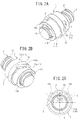
FIG. 1 is a perspective view illustrating a ball screw in a first embodiment; -
FIG. 2A is a right perspective view illustrating a ball screw in a second embodiment; -
FIG. 2B is a left perspective view of the ball screw; -
FIG. 2C is a front view of the ball screw; -
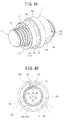
FIG. 3A is a perspective view illustrating a ball screw in a third embodiment; -
FIG. 3B is a front view of the ball screw; -
FIG. 4A is a perspective view illustrating a ball screw in a fourth embodiment; and -
FIG. 4B is a front view of the ball screw. - Hereinafter, although embodiments of the present invention will be described, the present invention is not limited to the following embodiments.
- As illustrated in
FIG. 1 , a ball screw of this embodiment has anut 1, ascrew shaft 2, and asingle piece 3. - The
nut 1 has acylindrical portion 11, aflange portion 12 formed at the center of thecylindrical portion 11 in an axial direction, and a protrudingportion 13 that protrudes from one end surface in the axial direction. Thecylindrical portion 11 is divided into afirst portion 11a in which the protrudingportion 13 is formed in the axial direction of thenut 1, and asecond portion 11b excluding the first portion, by theflange portion 12. Aperipheral groove 14 is formed at the boundary of thefirst portion 11a between thefirst portion 11a and theflange portion 12. A through-hole 15 passing through thenut 1 in a radial direction is a portion including theperipheral groove 14 of thefirst portion 11a in the axial direction, and is formed at the same position as the protrudingportion 13 in a circumferential direction. - An inner peripheral surface of the
cylindrical portion 11 has aspiral groove 110. An outer peripheral surface of thescrew shaft 2 is formed with aspiral groove 21. Plural balls are arranged between raceways formed by thespiral groove 110 of thenut 1 and thespiral groove 21 of thescrew shaft 2. - The
piece 3 has an elongated small piece shape, both ends of the piece in a longitudinal direction are formed in a substantially semicircular arc shape, a recessed portion along the longitudinal direction that forms a ball return passage is formed in one surface of the piece, and the other surface of the piece becomes a circumferential surface concentric with thecylindrical portion 11. Thepiece 3 is obtained by an injection molding method using PPS. Thepiece 3 is fitted to the through-hole 15 of thenut 1 such that a recessed portion side is directed to thescrew shaft 2 side. Accordingly, thepiece 3 is arranged at the same position as the protrudingportion 13 in the circumferential direction of thenut 1, and the inner peripheral surface of thenut 1 is formed with the ball return passage consisting of the - The protruding
portion 13 is made of steel and is formed integrally with the cylindrical portion 10. That is, the shape of thenut 1 is given by cutting a cylindrical material made of a steel material. A portion of thenut 1 in which thepiece 3 is fitted to the through-hole 15 is lighter than the other portions of thenut 1, and a portion of thenut 1 in which the protrudingportion 13 is formed is heavier than the other portions of thenut 1. - In the ball screw of this embodiment, the deviation of the center of gravity of the
nut 1 from a rotational center line caused by the protrudingportion 13 is eliminated or is made small by the recessed portion of thepiece 3 being arranged at the same position as the protrudingportion 13 in the circumferential direction of the nut 1 (that is, the configuration of the recessed portion that constitutes the ball return passage). - As illustrated in
FIG. 2 , a ball screw of this embodiment has thenut 1, thescrew shaft 2, and twopieces 3. - The
nut 1 has thecylindrical portion 11, theflange portion 12 formed at the center of thecylindrical portion 11 in the axial direction, and the protrudingportion 13 that protrudes from one end surface in the axial direction. Thecylindrical portion 11 is divided into thefirst portion 11a in which the protrudingportion 13 is formed in the axial direction of thenut 1, and thesecond portion 11b excluding the first portion, by theflange portion 12. - The
nut 1 has two through-holes nut 1 in the radial direction. One through-hole 15a is the portion of thefirst portion 11a including theflange portion 12 in the axial direction, and is formed at a position where acentral angle 01 based on the protrudingportion 13 in the circumferential direction becomes 57 degrees. The other through-hole 15b is the portion of thesecond portion 11b including theflange portion 12 in the axial direction, and is formed at a position where acentral angle 02 based on the protrudingportion 13 in the circumferential direction becomes 57 degrees. - The inner peripheral surface of the
cylindrical portion 11 is formed with thespiral groove 110. The outer peripheral surface of thescrew shaft 2 is formed with thespiral groove 21. The plurality of balls is arranged between the raceways formed by thespiral groove 110 of thenut 1 and thespiral groove 21 of thescrew shaft 2. - The two
pieces 3 are the same and have an elongated small piece shape, both ends of each piece in a longitudinal direction are formed in a substantially semicircular arc shape, a recessed portion along the longitudinal direction that forms a ball return passage is formed in one surface of the piece, and the other surface of the piece becomes a circumferential surface concentric with thecylindrical portion 11. Thepieces 3 are manufactured by a metal powder injection molding method using Fe-Ni-C (1 to 8% Ni and 0.8% C). Thepieces 3 are fitted to the through-holes nut 1 such that recessed portion sides are directed to thescrew shaft 2 side. Accordingly, the twopieces 3 are arranged at positions where central angles θ1 and θ2 based on the protrudingportion 13 in the circumferential direction of anut 1 become 57 degrees, respectively, and the inner peripheral surface of thenut 1 is formed with two ball return passages consisting of the recessed portions of the - The protruding
portion 13 is made of steel and is formed integrally with the cylindrical portion 10. That is, the shape of thenut 1 is given by cutting a cylindrical material made of a steel material. Portions of thenut 1 in which thepieces 3 are fitted to the through-holes nut 1, and a portion of thenut 1 in which the protrudingportion 13 is formed is heavier than the other portions of thenut 1. - In the ball screw of this embodiment, the deviation of the center of gravity of the
nut 1 from the rotational center line caused by the protrudingportion 13 is eliminated or is made small by the recessed portions of thepieces 3 being arranged at positions where the central angles based on the protrudingportion 13 in the circumferential direction of thenut 1 become equal to or lower than 90 degrees (that is, the configuration of the recessed portions that constitute the ball return passages). - As illustrated in
FIG. 3 , a ball screw of this embodiment has thenut 1, thescrew shaft 2, and threepieces 3a to 3c. - The
nut 1 has thecylindrical portion 11, theflange portion 12 formed at the center of thecylindrical portion 11 in the axial direction, and the protrudingportion 13 that protrudes from one end surface in the axial direction. Thecylindrical portion 11 is divided into thefirst portion 11a in which the protrudingportion 13 is formed in the axial direction of thenut 1, and thesecond portion 11b excluding the first portion, by theflange portion 12. Theperipheral groove 14 is formed at the boundary of thefirst portion 11a between thefirst portion 11a and theflange portion 12. - The
nut 1 is formed with three through-holes 15a to 15c passing through the nut in the radial direction. A first through-hole 15a is a portion including theperipheral groove 14 of thefirst portion 11a in the axial direction, and is formed at the same position as the protrudingportion 13 in the circumferential direction. A second through-hole 15b is formed in thesecond portion 11b in the axial direction. A third through-hole 15c is formed in thesecond portion 11b in the axial direction. The three through-holes 15a to 15c are formed at equal intervals (θ1 = θ2 = 03 = 120 degrees) in the circumferential directions of thenut 1. - The three
pieces 3 have an elongated small piece shape, both ends of each piece in a longitudinal direction are formed in a substantially semicircular arc shape, a recessed portion along the longitudinal direction that forms a ball return passage is formed in one surface of the piece, and the other surface of the piece becomes a circumferential surface concentric with thecylindrical portion 11. Although the threepieces 3 have the same dimensions, thefirst piece 3a is obtained by an injection molding method using PPS, and thesecond piece 3b and thethird piece 3c are manufactured by a metal powder injection molding method using Fe-Ni-C (1 to 8% Ni and 0.8% C) . Thepieces 3a to 3c are respectively fitted to the through-holes 15a to 15c of thenut 1 such that recessed portion sides are directed to thescrew shaft 2 side. Accordingly, thefirst piece 3a is arranged at the same position as the protrudingportion 13 in the circumferential direction of thenut 1, and the threepieces 3 are arranged at equal intervals (θ1 = θ2 = 03 = 120 degrees) in the circumferential directions of thenut 1, and the inner peripheral surface of thenut 1 is formed with three ball return passages consisting of the recessed portions of therespective pieces 3. - The protruding
portion 13 is made of steel and is formed integrally with the cylindrical portion 10. That is, the shape of thenut 1 is given by cutting a cylindrical material made of a steel material. Portions of thenut 1 in which thepieces 3a to 3c are fitted to the through-holes 15a to 15c are lighter than the other portions of thenut 1, and a portion of thenut 1 in which the protrudingportion 13 is formed is heavier than the other portions of thenut 1. - In the ball screw of this embodiment, the
nut 1 has the threepieces 3a to 3c, all thepieces 3a to 3c have the same dimensions and are arranged at equal intervals in the circumferential direction of thenut 1, thefirst piece 3a is arranged at the same position as the protrudingportion 13 in the circumferential direction of thenut 1, and the deviation of the center of gravity of thenut 1 from the rotational center line caused by the protrudingportion 13 is eliminated or is made small by thefirst piece 3a being made of a material with a smaller specific gravity than thesecond piece 3b and thethird piece 3c (that is, the configuration of the recessed portions that constitute the ball return passages). - Additionally, by forming the
first piece 3a using a material with a smaller specific gravity than thesecond piece 3b and thethird piece 3c, even if all thepieces 3a to 3c are made to have the same dimensions, all thepieces 3a to 3c are able to be arranged at equal intervals in the circumferential direction of thenut 1. Therefore, the distribution of load in the axial direction of the ball screw is able to be made uniform. - As illustrated in
FIG. 4 , a ball screw of this embodiment has thenut 1, thescrew shaft 2, and the threepieces 3a to 3c. - The
nut 1 has thecylindrical portion 11, theflange portion 12 formed at the center of thecylindrical portion 11 in the axial direction, and the protrudingportion 13 that protrudes from one end surface in the axial direction. Thecylindrical portion 11 is divided into thefirst portion 11a in which the protrudingportion 13 is formed in the axial direction of thenut 1, and the second portion lib excluding the first portion, by theflange portion 12. Theperipheral groove 14 is formed at the boundary of thefirst portion 11a between thefirst portion 11a and theflange portion 12. - The
nut 1 is formed with the three through-holes 15a to 15c passing through the nut in the radial direction. The first through-hole 15a is a portion including theperipheral groove 14 of thefirst portion 11a in the axial direction, and is formed at the same position as the protrudingportion 13 in the circumferential direction. The second through-hole 15b is formed in thesecond portion 11b in the axial direction. The third through-hole 15c is formed in thesecond portion 11b in the axial direction. The three through-holes 15a to 15c are formed at equal intervals (θ1 = θ2 = θ3 = 120 degrees) in the circumferential directions of thenut 1. The second through-hole 15b and the third through-hole 15c have the same dimensions, and the dimensions of the first through-hole 15a are smaller than those of the second through-hole 15b and the third through-hole 15c. - The three
pieces 3 have an elongated small piece shape, both ends of each piece in a longitudinal direction are formed in a substantially semicircular arc shape, a recessed portion along the longitudinal direction that forms a ball return passage is formed in one surface of the piece, and the other surface of the piece becomes a circumferential surface concentric with thecylindrical portion 11. The threepieces 3 are manufactured by a metal powder injection molding method using the same Fe-Ni-C (1 to 8% Ni and 0.8% C). Thesecond piece 3b and thethird piece 3c have the same dimensions, and the dimensions of thefirst piece 3a are smaller than the dimensions of thesecond piece 3b and thethird piece 3c. - The
pieces 3a to 3c are respectively fitted to the through-holes 15a to 15c of thenut 1 such that recessed portion sides are directed to thescrew shaft 2 side. Accordingly, thefirst piece 3a is arranged at the same position as the protrudingportion 13 in the circumferential direction of thenut 1, and the threepieces 3 are arranged at equal intervals (θ1 = θ2 = θ3 = 120 degrees) in the circumferential directions of thenut 1, and the inner peripheral surface of thenut 1 is formed with three ball return passages consisting of the recessed portions of therespective pieces 3. - The protruding
portion 13 is made of steel and is formed integrally with the cylindrical portion 10. That is, the shape of thenut 1 is given by cutting a cylindrical material made of a steel material. Portions of thenut 1 in which thepieces 3a to 3c are fitted to the through-holes 15a to 15c are lighter than the other portions of thenut 1, and a portion of thenut 1 in which the protrudingportion 13 is formed is heavier than the other portions of thenut 1. - In the ball screw of this embodiment, the
nut 1 has the threepieces 3a to 3c, all thepieces 3a to 3c are arranged at equal intervals in the circumferential direction of thenut 1, thefirst piece 3a is arranged at the same position as the protrudingportion 13 in the circumferential direction of thenut 1, and the deviation of the center of gravity of thenut 1 from the rotational center line caused by the protrudingportion 13 is eliminated or is made small by thefirst piece 3a having smaller dimensions than thesecond piece 3b and thethird piece 3c (that is, the configuration of the recessed portions that constitute the ball return passages). - Additionally, by making the dimensions of the
first piece 3a smaller than those of thesecond piece 3b and thethird piece 3c, all thepieces 3a to 3c are able to be arranged at equal intervals in the circumferential direction of thenut 1 while all thepieces 3a to 3c are made of the same material. Therefore, the distribution of load in the axial direction of the ball screw is able to be made uniform. - In addition, when the dimensions of the
first piece 3a are not able to be made much smaller than those of thesecond piece 3b and thethird piece 3c, and when the deviation of the center of gravity of thenut 1 from the rotational center line caused by the protrudingportion 13 is not eliminated if all thepieces 3a to 3c are formed of the same material, the deviation is also able to be eliminated by forming thefirst piece 3a using a material with a smaller specific gravity than thesecond piece 3b andthird piece 3c. - In addition, the present invention relates to the ball screw which has the protruding portion protruding from the axial end surface, in which the center of gravity of the nut deviates from the rotational center line of the nut. However, even in the ball screw in which the groove that extends in an axial direction is formed in the outer peripheral surface of the nut, the center of gravity of the nut deviates from the rotational center line of the nut. In the case of such a ball screw, the deviation of the center of gravity of the nut from the rotational center line is able to be made small also by forming the recessed portion, which constitutes the ball return passage formed in the inner peripheral surface of the nut, at a suitable position outside of the formation position of the groove.
- Additionally, the axial end of the spiral groove formed in the inner peripheral surface of the nut is an incomplete threaded portion, and the presence of the incomplete threaded portion becomes a cause by which the center of gravity of the nut deviates from the rotational center line of the nut. However, the deviation of the center of gravity of the nut from the rotational center line is able to be made small also by forming the recessed portion, which constitutes the ball return passage formed in the inner peripheral surface of the nut, at a position outside of the incomplete threaded portion.
-
- 1
- nut
- 11
- cylindrical portion
- 11a
- first portion
- 11b
- second portion
- 12
- flange portion
- 13
- protruding portion
- 14
- peripheral groove
- 15
- through-hole
- 15a
- first through-hole
- 15b
- second through-hole
- 15c
- third through-hole
- 110
- spiral groove of nut
- 2
- screw shaft
- 21
- spiral groove of screw shaft
- 3
- segment
- 3a
- first segment
- 3b
- second segment (other segment)
- 3c
- third segment (other segment)
Claims (6)
- A ball screw, comprising:a nut having a spiral groove formed on an inner peripheral surface;a screw shaft having a spiral groove formed on an outer peripheral surface;balls arranged between a raceway formed by the spiral groove of the nut and the spiral groove of the screw shaft; anda ball return passage configured to return the balls from an end point of the raceway to a start point of the raceway,wherein the balls roll within the raceway and the screw shaft moves in an axial direction when the nut rotates,wherein the nut includes a protruding portion configured to protrude from an axial end surface,wherein the ball return passage is a recessed portion formed on the inner peripheral surface of the nut, andwherein a center of gravity of the nut deviates from a rotational center line due to the protruding portion, and deviation is made smaller by the recessed portion.
- The ball screw according to claim 1,
wherein the nut includes the recessed portion, and
wherein the recessed portion is arranged at a position same as the position of the protruding portion in the circumferential direction of the nut. - The ball screw according to claim 1,
wherein the nut includes two recessed portions, and
wherein the two recessed portions are arranged at the positions where central angles with the protruding portion being as a reference become 90 degrees or less in the circumferential direction of the nut. - The ball screw according to claim 2 or claim 3,
wherein the recessed portion is formed by a piece being fitted into a through-hole passing through the nut in a radial direction, and
wherein the piece is made of synthetic resin. - The ball screw according to claim 1,
wherein the recessed portion is formed by a piece being fitted into a through-hole passing through the nut in a radial direction,
wherein the nut includes at least three pieces,
wherein all the pieces have the same dimensions and are arranged at equal intervals in the circumferential direction of the nut, and
wherein a first one of the pieces is arranged at the position same as the position of the protruding portion in the circumferential direction of the nut and is made of a material with a specific gravity smaller than the specific gravities of the other pieces. - The ball screw according to claim 1,
wherein the recessed portion is formed by a piece being fitted into a through-hole passing through the nut in a radial direction,
wherein the nut includes at least three pieces,
wherein all the pieces are arranged at equal intervals in the circumferential direction of the nut, and
wherein a first one of the pieces is arranged at the position same as the position of the protruding portion in the circumferential direction of the nut, and has dimensions smaller than the dimensions of the other pieces.
Applications Claiming Priority (2)
| Application Number | Priority Date | Filing Date | Title |
|---|---|---|---|
| JP2013194582A JP5648727B1 (en) | 2013-09-19 | 2013-09-19 | Ball screw |
| PCT/JP2014/000525 WO2015040766A1 (en) | 2013-09-19 | 2014-01-31 | Ball screw |
Publications (3)
| Publication Number | Publication Date |
|---|---|
| EP3018385A1 true EP3018385A1 (en) | 2016-05-11 |
| EP3018385A4 EP3018385A4 (en) | 2017-06-07 |
| EP3018385B1 EP3018385B1 (en) | 2020-06-10 |
Family
ID=52344795
Family Applications (1)
| Application Number | Title | Priority Date | Filing Date |
|---|---|---|---|
| EP14846270.8A Active EP3018385B1 (en) | 2013-09-19 | 2014-01-31 | Ball screw |
Country Status (5)
| Country | Link |
|---|---|
| US (1) | US20160223059A1 (en) |
| EP (1) | EP3018385B1 (en) |
| JP (1) | JP5648727B1 (en) |
| CN (1) | CN104662330B (en) |
| WO (1) | WO2015040766A1 (en) |
Families Citing this family (5)
| Publication number | Priority date | Publication date | Assignee | Title |
|---|---|---|---|---|
| KR101650443B1 (en) * | 2015-03-20 | 2016-08-23 | 이래오토모티브시스템 주식회사 | Electric parking brake |
| DE102015209643B3 (en) * | 2015-05-27 | 2016-11-10 | Schaeffler Technologies AG & Co. KG | Ball Screw |
| CN105042000A (en) * | 2015-06-29 | 2015-11-11 | 柳州蚊敌香业有限公司 | Ball screw without cut-down machining part |
| US20180202525A1 (en) * | 2015-07-14 | 2018-07-19 | Nsk Ltd. | Ball Screw, Machine Tool, and Conveying Device |
| EP4134569A4 (en) * | 2021-04-21 | 2023-10-11 | NSK Ltd. | Ball screw device |
Family Cites Families (13)
| Publication number | Priority date | Publication date | Assignee | Title |
|---|---|---|---|---|
| JPH11147566A (en) * | 1997-11-11 | 1999-06-02 | Tdk Corp | Display product package |
| NL1010576C2 (en) * | 1998-11-17 | 2000-05-18 | Skf Eng & Res Centre Bv | Screw actuator, comprising a multifunctional sleeve and a claw. |
| EP1193422B1 (en) * | 2000-09-29 | 2004-01-21 | THK Co., Ltd. | Screw assembly having deflector and method of manufacturing same |
| JP3907954B2 (en) * | 2001-02-08 | 2007-04-18 | Ntn株式会社 | Ball screw and electric power steering apparatus including the same |
| DE102004004145B3 (en) * | 2004-01-28 | 2005-09-29 | Neff Antriebstechnik Automation Gmbh | Method for producing a spindle nut with gear deflection for a ball screw and ball screw with gear deflection |
| JP2005299719A (en) * | 2004-04-07 | 2005-10-27 | Ntn Corp | Automobile ball screw |
| EP1914447B1 (en) * | 2005-07-29 | 2012-09-26 | Thk Co., Ltd. | Method of producing screw device, and screw device |
| JP2010038217A (en) * | 2008-08-04 | 2010-02-18 | Jtekt Corp | Ball screw device |
| JP5420922B2 (en) * | 2009-02-06 | 2014-02-19 | 株式会社日本自動車部品総合研究所 | Electric power steering device |
| JP5293887B2 (en) * | 2010-04-26 | 2013-09-18 | 日本精工株式会社 | Linear actuator |
| CN102338199A (en) * | 2010-07-21 | 2012-02-01 | 蔡伟江 | Ball screw |
| JP2010270916A (en) * | 2010-09-09 | 2010-12-02 | Nsk Ltd | Ball screw mechanism |
| EP2642161B1 (en) * | 2010-11-15 | 2020-06-24 | NSK Ltd. | Ball screw |
-
2013
- 2013-09-19 JP JP2013194582A patent/JP5648727B1/en active Active
-
2014
- 2014-01-31 US US15/021,340 patent/US20160223059A1/en not_active Abandoned
- 2014-01-31 CN CN201480000034.9A patent/CN104662330B/en active Active
- 2014-01-31 WO PCT/JP2014/000525 patent/WO2015040766A1/en active Application Filing
- 2014-01-31 EP EP14846270.8A patent/EP3018385B1/en active Active
Also Published As
| Publication number | Publication date |
|---|---|
| US20160223059A1 (en) | 2016-08-04 |
| EP3018385B1 (en) | 2020-06-10 |
| CN104662330A (en) | 2015-05-27 |
| CN104662330B (en) | 2017-05-17 |
| JP5648727B1 (en) | 2015-01-07 |
| EP3018385A4 (en) | 2017-06-07 |
| JP2015059633A (en) | 2015-03-30 |
| WO2015040766A1 (en) | 2015-03-26 |
Similar Documents
| Publication | Publication Date | Title |
|---|---|---|
| EP3018385B1 (en) | Ball screw | |
| EP3564055B1 (en) | Battery securing device, traction battery comprising the same and vehicle | |
| US9452773B2 (en) | Power steering apparatus | |
| US10228047B2 (en) | Actuator for providing relative motion between two points | |
| US9242542B2 (en) | System for reducing engine roll | |
| US20170097071A1 (en) | Steering column for a motor vehicle, threaded rod and spindle nut | |
| US20120247240A1 (en) | Linear Actuator | |
| DE112010004590T5 (en) | Electric actuator | |
| EP3075627B1 (en) | Steering column device | |
| EP2620832A2 (en) | Coupling device for at least one motor vehicle pedal | |
| EP2515000A1 (en) | Ball screw assembly with recirculating cap and nut | |
| US9512875B2 (en) | Bearing unit | |
| TW201719057A (en) | Actuator | |
| DE102017211399A1 (en) | ELECTRIC POWER STEERING DEVICE FROM THE GEAR SUPPORT TYPE | |
| US9428217B2 (en) | Steering apparatus | |
| US20160091052A1 (en) | Actuator and electronic equipment having the same | |
| US20180102635A1 (en) | Fixing structure and electrical connection box | |
| CN104742956B (en) | Steering link structure of rear wheel steering device | |
| EP3324077B1 (en) | Ball screw, machine tool, and conveying device | |
| JP2016176540A (en) | Electric actuator | |
| EP2136105B1 (en) | A ball screw spindle comprising a metallic deflector member | |
| US9765876B2 (en) | Backlash adjusting method and gear mechanism | |
| US9377092B2 (en) | Ball screw deflector | |
| US20200347889A1 (en) | Screw nut or spline nut | |
| EP2626594A1 (en) | Worm Wheel |
Legal Events
| Date | Code | Title | Description |
|---|---|---|---|
| PUAI | Public reference made under article 153(3) epc to a published international application that has entered the european phase |
Free format text: ORIGINAL CODE: 0009012 |
|
| 17P | Request for examination filed |
Effective date: 20160205 |
|
| AK | Designated contracting states |
Kind code of ref document: A1 Designated state(s): AL AT BE BG CH CY CZ DE DK EE ES FI FR GB GR HR HU IE IS IT LI LT LU LV MC MK MT NL NO PL PT RO RS SE SI SK SM TR |
|
| AX | Request for extension of the european patent |
Extension state: BA ME |
|
| DAX | Request for extension of the european patent (deleted) | ||
| A4 | Supplementary search report drawn up and despatched |
Effective date: 20170510 |
|
| RIC1 | Information provided on ipc code assigned before grant |
Ipc: F16H 25/24 20060101AFI20170503BHEP Ipc: F16H 25/22 20060101ALI20170503BHEP |
|
| STAA | Information on the status of an ep patent application or granted ep patent |
Free format text: STATUS: EXAMINATION IS IN PROGRESS |
|
| 17Q | First examination report despatched |
Effective date: 20190909 |
|
| REG | Reference to a national code |
Ref country code: DE Ref legal event code: R079 Ref document number: 602014066537 Country of ref document: DE Free format text: PREVIOUS MAIN CLASS: F16H0025240000 Ipc: F16H0025220000 |
|
| GRAP | Despatch of communication of intention to grant a patent |
Free format text: ORIGINAL CODE: EPIDOSNIGR1 |
|
| STAA | Information on the status of an ep patent application or granted ep patent |
Free format text: STATUS: GRANT OF PATENT IS INTENDED |
|
| RIC1 | Information provided on ipc code assigned before grant |
Ipc: F16H 25/22 20060101AFI20200113BHEP |
|
| INTG | Intention to grant announced |
Effective date: 20200210 |
|
| GRAS | Grant fee paid |
Free format text: ORIGINAL CODE: EPIDOSNIGR3 |
|
| GRAA | (expected) grant |
Free format text: ORIGINAL CODE: 0009210 |
|
| STAA | Information on the status of an ep patent application or granted ep patent |
Free format text: STATUS: THE PATENT HAS BEEN GRANTED |
|
| AK | Designated contracting states |
Kind code of ref document: B1 Designated state(s): AL AT BE BG CH CY CZ DE DK EE ES FI FR GB GR HR HU IE IS IT LI LT LU LV MC MK MT NL NO PL PT RO RS SE SI SK SM TR |
|
| REG | Reference to a national code |
Ref country code: GB Ref legal event code: FG4D |
|
| REG | Reference to a national code |
Ref country code: AT Ref legal event code: REF Ref document number: 1279443 Country of ref document: AT Kind code of ref document: T Effective date: 20200615 Ref country code: CH Ref legal event code: EP |
|
| REG | Reference to a national code |
Ref country code: DE Ref legal event code: R096 Ref document number: 602014066537 Country of ref document: DE |
|
| REG | Reference to a national code |
Ref country code: IE Ref legal event code: FG4D |
|
| REG | Reference to a national code |
Ref country code: LT Ref legal event code: MG4D |
|
| PG25 | Lapsed in a contracting state [announced via postgrant information from national office to epo] |
Ref country code: GR Free format text: LAPSE BECAUSE OF FAILURE TO SUBMIT A TRANSLATION OF THE DESCRIPTION OR TO PAY THE FEE WITHIN THE PRESCRIBED TIME-LIMIT Effective date: 20200911 Ref country code: SE Free format text: LAPSE BECAUSE OF FAILURE TO SUBMIT A TRANSLATION OF THE DESCRIPTION OR TO PAY THE FEE WITHIN THE PRESCRIBED TIME-LIMIT Effective date: 20200610 Ref country code: NO Free format text: LAPSE BECAUSE OF FAILURE TO SUBMIT A TRANSLATION OF THE DESCRIPTION OR TO PAY THE FEE WITHIN THE PRESCRIBED TIME-LIMIT Effective date: 20200910 Ref country code: FI Free format text: LAPSE BECAUSE OF FAILURE TO SUBMIT A TRANSLATION OF THE DESCRIPTION OR TO PAY THE FEE WITHIN THE PRESCRIBED TIME-LIMIT Effective date: 20200610 Ref country code: LT Free format text: LAPSE BECAUSE OF FAILURE TO SUBMIT A TRANSLATION OF THE DESCRIPTION OR TO PAY THE FEE WITHIN THE PRESCRIBED TIME-LIMIT Effective date: 20200610 |
|
| REG | Reference to a national code |
Ref country code: NL Ref legal event code: MP Effective date: 20200610 |
|
| PG25 | Lapsed in a contracting state [announced via postgrant information from national office to epo] |
Ref country code: HR Free format text: LAPSE BECAUSE OF FAILURE TO SUBMIT A TRANSLATION OF THE DESCRIPTION OR TO PAY THE FEE WITHIN THE PRESCRIBED TIME-LIMIT Effective date: 20200610 Ref country code: LV Free format text: LAPSE BECAUSE OF FAILURE TO SUBMIT A TRANSLATION OF THE DESCRIPTION OR TO PAY THE FEE WITHIN THE PRESCRIBED TIME-LIMIT Effective date: 20200610 Ref country code: RS Free format text: LAPSE BECAUSE OF FAILURE TO SUBMIT A TRANSLATION OF THE DESCRIPTION OR TO PAY THE FEE WITHIN THE PRESCRIBED TIME-LIMIT Effective date: 20200610 Ref country code: BG Free format text: LAPSE BECAUSE OF FAILURE TO SUBMIT A TRANSLATION OF THE DESCRIPTION OR TO PAY THE FEE WITHIN THE PRESCRIBED TIME-LIMIT Effective date: 20200910 |
|
| REG | Reference to a national code |
Ref country code: AT Ref legal event code: MK05 Ref document number: 1279443 Country of ref document: AT Kind code of ref document: T Effective date: 20200610 |
|
| PG25 | Lapsed in a contracting state [announced via postgrant information from national office to epo] |
Ref country code: NL Free format text: LAPSE BECAUSE OF FAILURE TO SUBMIT A TRANSLATION OF THE DESCRIPTION OR TO PAY THE FEE WITHIN THE PRESCRIBED TIME-LIMIT Effective date: 20200610 Ref country code: AL Free format text: LAPSE BECAUSE OF FAILURE TO SUBMIT A TRANSLATION OF THE DESCRIPTION OR TO PAY THE FEE WITHIN THE PRESCRIBED TIME-LIMIT Effective date: 20200610 |
|
| PG25 | Lapsed in a contracting state [announced via postgrant information from national office to epo] |
Ref country code: PT Free format text: LAPSE BECAUSE OF FAILURE TO SUBMIT A TRANSLATION OF THE DESCRIPTION OR TO PAY THE FEE WITHIN THE PRESCRIBED TIME-LIMIT Effective date: 20201012 Ref country code: ES Free format text: LAPSE BECAUSE OF FAILURE TO SUBMIT A TRANSLATION OF THE DESCRIPTION OR TO PAY THE FEE WITHIN THE PRESCRIBED TIME-LIMIT Effective date: 20200610 Ref country code: CZ Free format text: LAPSE BECAUSE OF FAILURE TO SUBMIT A TRANSLATION OF THE DESCRIPTION OR TO PAY THE FEE WITHIN THE PRESCRIBED TIME-LIMIT Effective date: 20200610 Ref country code: AT Free format text: LAPSE BECAUSE OF FAILURE TO SUBMIT A TRANSLATION OF THE DESCRIPTION OR TO PAY THE FEE WITHIN THE PRESCRIBED TIME-LIMIT Effective date: 20200610 Ref country code: IT Free format text: LAPSE BECAUSE OF FAILURE TO SUBMIT A TRANSLATION OF THE DESCRIPTION OR TO PAY THE FEE WITHIN THE PRESCRIBED TIME-LIMIT Effective date: 20200610 Ref country code: RO Free format text: LAPSE BECAUSE OF FAILURE TO SUBMIT A TRANSLATION OF THE DESCRIPTION OR TO PAY THE FEE WITHIN THE PRESCRIBED TIME-LIMIT Effective date: 20200610 Ref country code: SM Free format text: LAPSE BECAUSE OF FAILURE TO SUBMIT A TRANSLATION OF THE DESCRIPTION OR TO PAY THE FEE WITHIN THE PRESCRIBED TIME-LIMIT Effective date: 20200610 Ref country code: EE Free format text: LAPSE BECAUSE OF FAILURE TO SUBMIT A TRANSLATION OF THE DESCRIPTION OR TO PAY THE FEE WITHIN THE PRESCRIBED TIME-LIMIT Effective date: 20200610 |
|
| PG25 | Lapsed in a contracting state [announced via postgrant information from national office to epo] |
Ref country code: IS Free format text: LAPSE BECAUSE OF FAILURE TO SUBMIT A TRANSLATION OF THE DESCRIPTION OR TO PAY THE FEE WITHIN THE PRESCRIBED TIME-LIMIT Effective date: 20201010 Ref country code: SK Free format text: LAPSE BECAUSE OF FAILURE TO SUBMIT A TRANSLATION OF THE DESCRIPTION OR TO PAY THE FEE WITHIN THE PRESCRIBED TIME-LIMIT Effective date: 20200610 Ref country code: PL Free format text: LAPSE BECAUSE OF FAILURE TO SUBMIT A TRANSLATION OF THE DESCRIPTION OR TO PAY THE FEE WITHIN THE PRESCRIBED TIME-LIMIT Effective date: 20200610 |
|
| REG | Reference to a national code |
Ref country code: DE Ref legal event code: R097 Ref document number: 602014066537 Country of ref document: DE |
|
| PLBE | No opposition filed within time limit |
Free format text: ORIGINAL CODE: 0009261 |
|
| STAA | Information on the status of an ep patent application or granted ep patent |
Free format text: STATUS: NO OPPOSITION FILED WITHIN TIME LIMIT |
|
| PG25 | Lapsed in a contracting state [announced via postgrant information from national office to epo] |
Ref country code: DK Free format text: LAPSE BECAUSE OF FAILURE TO SUBMIT A TRANSLATION OF THE DESCRIPTION OR TO PAY THE FEE WITHIN THE PRESCRIBED TIME-LIMIT Effective date: 20200610 |
|
| 26N | No opposition filed |
Effective date: 20210311 |
|
| PG25 | Lapsed in a contracting state [announced via postgrant information from national office to epo] |
Ref country code: SI Free format text: LAPSE BECAUSE OF FAILURE TO SUBMIT A TRANSLATION OF THE DESCRIPTION OR TO PAY THE FEE WITHIN THE PRESCRIBED TIME-LIMIT Effective date: 20200610 |
|
| PG25 | Lapsed in a contracting state [announced via postgrant information from national office to epo] |
Ref country code: MC Free format text: LAPSE BECAUSE OF FAILURE TO SUBMIT A TRANSLATION OF THE DESCRIPTION OR TO PAY THE FEE WITHIN THE PRESCRIBED TIME-LIMIT Effective date: 20200610 |
|
| REG | Reference to a national code |
Ref country code: CH Ref legal event code: PL |
|
| GBPC | Gb: european patent ceased through non-payment of renewal fee |
Effective date: 20210131 |
|
| PG25 | Lapsed in a contracting state [announced via postgrant information from national office to epo] |
Ref country code: LU Free format text: LAPSE BECAUSE OF NON-PAYMENT OF DUE FEES Effective date: 20210131 |
|
| REG | Reference to a national code |
Ref country code: BE Ref legal event code: MM Effective date: 20210131 |
|
| PG25 | Lapsed in a contracting state [announced via postgrant information from national office to epo] |
Ref country code: FR Free format text: LAPSE BECAUSE OF NON-PAYMENT OF DUE FEES Effective date: 20210131 |
|
| PG25 | Lapsed in a contracting state [announced via postgrant information from national office to epo] |
Ref country code: GB Free format text: LAPSE BECAUSE OF NON-PAYMENT OF DUE FEES Effective date: 20210131 Ref country code: CH Free format text: LAPSE BECAUSE OF NON-PAYMENT OF DUE FEES Effective date: 20210131 Ref country code: LI Free format text: LAPSE BECAUSE OF NON-PAYMENT OF DUE FEES Effective date: 20210131 |
|
| PG25 | Lapsed in a contracting state [announced via postgrant information from national office to epo] |
Ref country code: IE Free format text: LAPSE BECAUSE OF NON-PAYMENT OF DUE FEES Effective date: 20210131 |
|
| PG25 | Lapsed in a contracting state [announced via postgrant information from national office to epo] |
Ref country code: IS Free format text: LAPSE BECAUSE OF FAILURE TO SUBMIT A TRANSLATION OF THE DESCRIPTION OR TO PAY THE FEE WITHIN THE PRESCRIBED TIME-LIMIT Effective date: 20201010 |
|
| PG25 | Lapsed in a contracting state [announced via postgrant information from national office to epo] |
Ref country code: BE Free format text: LAPSE BECAUSE OF NON-PAYMENT OF DUE FEES Effective date: 20210131 |
|
| PG25 | Lapsed in a contracting state [announced via postgrant information from national office to epo] |
Ref country code: HU Free format text: LAPSE BECAUSE OF FAILURE TO SUBMIT A TRANSLATION OF THE DESCRIPTION OR TO PAY THE FEE WITHIN THE PRESCRIBED TIME-LIMIT; INVALID AB INITIO Effective date: 20140131 |
|
| PG25 | Lapsed in a contracting state [announced via postgrant information from national office to epo] |
Ref country code: CY Free format text: LAPSE BECAUSE OF FAILURE TO SUBMIT A TRANSLATION OF THE DESCRIPTION OR TO PAY THE FEE WITHIN THE PRESCRIBED TIME-LIMIT Effective date: 20200610 |
|
| PG25 | Lapsed in a contracting state [announced via postgrant information from national office to epo] |
Ref country code: MK Free format text: LAPSE BECAUSE OF FAILURE TO SUBMIT A TRANSLATION OF THE DESCRIPTION OR TO PAY THE FEE WITHIN THE PRESCRIBED TIME-LIMIT Effective date: 20200610 |
|
| PGFP | Annual fee paid to national office [announced via postgrant information from national office to epo] |
Ref country code: DE Payment date: 20231205 Year of fee payment: 11 |