EP3018347A1 - Variable displacement compressor with an oil check valve - Google Patents
Variable displacement compressor with an oil check valve Download PDFInfo
- Publication number
- EP3018347A1 EP3018347A1 EP15185467.6A EP15185467A EP3018347A1 EP 3018347 A1 EP3018347 A1 EP 3018347A1 EP 15185467 A EP15185467 A EP 15185467A EP 3018347 A1 EP3018347 A1 EP 3018347A1
- Authority
- EP
- European Patent Office
- Prior art keywords
- compressor
- check valve
- spring
- discharge chamber
- control valve
- Prior art date
- Legal status (The legal status is an assumption and is not a legal conclusion. Google has not performed a legal analysis and makes no representation as to the accuracy of the status listed.)
- Withdrawn
Links
Images
Classifications
-
- F—MECHANICAL ENGINEERING; LIGHTING; HEATING; WEAPONS; BLASTING
- F04—POSITIVE - DISPLACEMENT MACHINES FOR LIQUIDS; PUMPS FOR LIQUIDS OR ELASTIC FLUIDS
- F04B—POSITIVE-DISPLACEMENT MACHINES FOR LIQUIDS; PUMPS
- F04B53/00—Component parts, details or accessories not provided for in, or of interest apart from, groups F04B1/00 - F04B23/00 or F04B39/00 - F04B47/00
- F04B53/10—Valves; Arrangement of valves
- F04B53/1002—Ball valves
-
- F—MECHANICAL ENGINEERING; LIGHTING; HEATING; WEAPONS; BLASTING
- F04—POSITIVE - DISPLACEMENT MACHINES FOR LIQUIDS; PUMPS FOR LIQUIDS OR ELASTIC FLUIDS
- F04B—POSITIVE-DISPLACEMENT MACHINES FOR LIQUIDS; PUMPS
- F04B27/00—Multi-cylinder pumps specially adapted for elastic fluids and characterised by number or arrangement of cylinders
- F04B27/08—Multi-cylinder pumps specially adapted for elastic fluids and characterised by number or arrangement of cylinders having cylinders coaxial with, or parallel or inclined to, main shaft axis
- F04B27/14—Control
- F04B27/16—Control of pumps with stationary cylinders
- F04B27/18—Control of pumps with stationary cylinders by varying the relative positions of a swash plate and a cylinder block
- F04B27/1804—Controlled by crankcase pressure
-
- F—MECHANICAL ENGINEERING; LIGHTING; HEATING; WEAPONS; BLASTING
- F04—POSITIVE - DISPLACEMENT MACHINES FOR LIQUIDS; PUMPS FOR LIQUIDS OR ELASTIC FLUIDS
- F04B—POSITIVE-DISPLACEMENT MACHINES FOR LIQUIDS; PUMPS
- F04B39/00—Component parts, details, or accessories, of pumps or pumping systems specially adapted for elastic fluids, not otherwise provided for in, or of interest apart from, groups F04B25/00 - F04B37/00
- F04B39/0027—Pulsation and noise damping means
-
- F—MECHANICAL ENGINEERING; LIGHTING; HEATING; WEAPONS; BLASTING
- F04—POSITIVE - DISPLACEMENT MACHINES FOR LIQUIDS; PUMPS FOR LIQUIDS OR ELASTIC FLUIDS
- F04B—POSITIVE-DISPLACEMENT MACHINES FOR LIQUIDS; PUMPS
- F04B39/00—Component parts, details, or accessories, of pumps or pumping systems specially adapted for elastic fluids, not otherwise provided for in, or of interest apart from, groups F04B25/00 - F04B37/00
- F04B39/0027—Pulsation and noise damping means
- F04B39/0055—Pulsation and noise damping means with a special shape of fluid passage, e.g. bends, throttles, diameter changes, pipes
-
- F—MECHANICAL ENGINEERING; LIGHTING; HEATING; WEAPONS; BLASTING
- F16—ENGINEERING ELEMENTS AND UNITS; GENERAL MEASURES FOR PRODUCING AND MAINTAINING EFFECTIVE FUNCTIONING OF MACHINES OR INSTALLATIONS; THERMAL INSULATION IN GENERAL
- F16K—VALVES; TAPS; COCKS; ACTUATING-FLOATS; DEVICES FOR VENTING OR AERATING
- F16K15/00—Check valves
- F16K15/02—Check valves with guided rigid valve members
- F16K15/04—Check valves with guided rigid valve members shaped as balls
- F16K15/044—Check valves with guided rigid valve members shaped as balls spring-loaded
-
- F—MECHANICAL ENGINEERING; LIGHTING; HEATING; WEAPONS; BLASTING
- F04—POSITIVE - DISPLACEMENT MACHINES FOR LIQUIDS; PUMPS FOR LIQUIDS OR ELASTIC FLUIDS
- F04B—POSITIVE-DISPLACEMENT MACHINES FOR LIQUIDS; PUMPS
- F04B27/00—Multi-cylinder pumps specially adapted for elastic fluids and characterised by number or arrangement of cylinders
- F04B27/08—Multi-cylinder pumps specially adapted for elastic fluids and characterised by number or arrangement of cylinders having cylinders coaxial with, or parallel or inclined to, main shaft axis
- F04B27/14—Control
- F04B27/16—Control of pumps with stationary cylinders
- F04B27/18—Control of pumps with stationary cylinders by varying the relative positions of a swash plate and a cylinder block
- F04B27/1804—Controlled by crankcase pressure
- F04B2027/1809—Controlled pressure
- F04B2027/1813—Crankcase pressure
-
- F—MECHANICAL ENGINEERING; LIGHTING; HEATING; WEAPONS; BLASTING
- F04—POSITIVE - DISPLACEMENT MACHINES FOR LIQUIDS; PUMPS FOR LIQUIDS OR ELASTIC FLUIDS
- F04B—POSITIVE-DISPLACEMENT MACHINES FOR LIQUIDS; PUMPS
- F04B27/00—Multi-cylinder pumps specially adapted for elastic fluids and characterised by number or arrangement of cylinders
- F04B27/08—Multi-cylinder pumps specially adapted for elastic fluids and characterised by number or arrangement of cylinders having cylinders coaxial with, or parallel or inclined to, main shaft axis
- F04B27/14—Control
- F04B27/16—Control of pumps with stationary cylinders
- F04B27/18—Control of pumps with stationary cylinders by varying the relative positions of a swash plate and a cylinder block
- F04B27/1804—Controlled by crankcase pressure
- F04B2027/1863—Controlled by crankcase pressure with an auxiliary valve, controlled by
- F04B2027/1872—Discharge pressure
Definitions
- This disclosure generally relates to variable displacement compressor, and more particularly relates to a check valve configured to prevent the flow of oil from the crankcase into the discharge chamber via a control valve of the compressor.
- variable displacement compressor for an air-conditioner system with an electronic control valve (ECV).
- ECV electronice control valve
- the compressor provides various passageways so pressure in various chambers within the compressor can be sensed by the ECV for the purpose of controlling the degree of displacement of the compressor.
- the chambers include a suction chamber having a suction pressure (PS), a discharge chamber having a discharge pressure (PD), and a crankcase having a crankcase pressure (PC).
- the crankcase typically contains oil for lubricating various moving parts within the crankcase.
- the passageways and the configuration of the ECV create a path that oil from the crankcase can flow into the discharge chamber during shipping and handling of a new (i.e. not installed in a vehicle) compressor.
- a discharge port plug is removed so the compressor can be connected to the rest of the air-conditioner system. If oil from the crankcase has accumulated in the discharge chamber, that oil may leak out of the compressor during the installation process and undesirably deposit on the vehicle or the person installing the compressor, and undesirably reduce the amount of oil in the compressor.
- a variable displacement compressor in accordance with one embodiment, includes a control valve and a check valve.
- the control valve is in fluidic communication with a discharge chamber of the compressor and a crankcase of the compressor.
- the check valve is interposed between the control valve and the discharge chamber. The check valve is configured to allow flow from the discharge chamber to the control valve and to prevent flow from the control valve to the discharge chamber.
- the check valve includes a ball and a spring.
- the spring is configured to urge the ball toward a closed position.
- the spring is characterized by a rate of the spring and a free-length of the spring, and the rate and the free length are selected to minimize de-stroke noise caused by a rapid change of the compressor operation to a low displacement state.
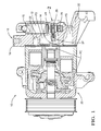
- Figs. 1 and 2 illustrate a non-limiting example of a variable displacement compressor, hereafter referred to as the compressor 10.
- the compressor 10 includes a control valve 12 for controlling the effective displacement of the compressor 10, as will be recognized by those in the art.
- the control valve 12 is in fluidic communication with a discharge chamber 14 of the compressor 10.
- the discharge chamber 14 couples compressed refrigerant to a discharge connection 16 which is illustrated as being plugged with a shipping cap 18.
- the control valve 12 is also in fluidic communication with a crankcase 20 of the compressor 10.
- the control valve 12 in this example controls or regulates a crankcase pressure PC in the crankcase 20 by applying varying portions of the discharge pressure PD from the discharge chamber 14, and the suction pressure PS from the suction chamber 22.
- the control valve defines a suction port 24 that is fluidicly coupled to the suction chamber 22, a discharge port 26 that is fluidicly coupled to the discharge chamber 14, and a crankcase port 28 that is fluidicly coupled to the crankcase 20.
- the control valve 12 typically has or defines a bleed path 30 ( Fig. 2 ) between the discharge port 26 and the crankcase port.
- the bleed path 30 is provided as a failsafe mechanism if the control valve 12 fails to operate. It is through the bleed path 30 that oil from the crankcase can reach the discharge port 26 during shipping and handling.
- the shipping cap 18 When the compressor 10 is installed in a vehicle (not shown), the shipping cap 18 is removed and an appropriate connection is made with, for example, a condenser (not shown) installed in the vehicle. While the discharge connection 16 is illustrated in an upward orientation such that an accumulation of oil in the discharge chamber 14 would not seem to be a problem, some applications install the compressor 10 such that the discharge connection 16 is oriented downward. In this situation, if oil has passed through the bleed path 30 and accumulated in the discharge chamber 14, that oil in the discharge chamber 14 may undesirably drain from the compressor 10 when the shipping cap 18 is removed. While the level of oil in the compressor 10 is not illustrated, those in the art will recognize that the oil level is a design choice and is typically selected such that less than half of the crankcase 20 is filled with oil when the compressor 10 is prepared for shipping.
- the compressor is equipped with a check valve 32 interposed between the control valve 12 and the discharge chamber 14.
- the check valve 32 is configured to allow flow of refrigerant from the discharge chamber 14 to the control valve 12, as is expected during normal operation.
- the check valve 32 is configured to prevent flow of, for example, oil from the control valve 12 (i.e. the crankcase 20) to the discharge chamber 14.
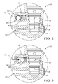
- Fig. 2 illustrates a non-limiting example of close-up of the check valve 32.
- the check valve 32 includes a ball 34, and a spring 36 configured to urge the ball 34 toward a closed position 38.
- the ball 34 When the ball 34 is in the closed position 38 as illustrated because, for example, there is no pressure difference between the discharge pressure PD and the crankcase pressure PC (i.e. the compressor 10 is not being operated), the ball 34 cooperates with the body of the check valve 32 to prevent oil in the crankcase 20 from flowing into the discharge chamber 14. This is advantageous as it prevents oil from accumulating in the discharge chamber 14 during shipping which could spill out of the compressor 10 if the shipping cap 18 was removed while the discharge connection 16 was oriented in a downward direction opposite of that illustrated in Fig. 1 .
- the check valve 32 provided an unexpected secondary benefit of reducing de-stroke noise created by a rapid change of the compressor operation to a low displacement state. While not subscribing to any particular theory, it is generally believed that much of the de-stroke noise is caused by the sudden rushing of refrigerant from the discharge chamber 14 to the crankcase 20 and the suction chamber 22 through the control valve 12, and/or the sudden change in position of various mechanical components within the compressor 10 related to varying the displacement of the compressor 10.
- Springs are characterized by a spring-rate or rate of the spring, and a free-length of the spring. Those in the art will recognize that both free-length and rate control the force that the spring 36 applies to the ball 34. It was recognized that if the rate of the spring 36 too high and/or the free-length of the spring 36 was too long, it would cause an undesirably high restriction through the check valve 32 and potentially make the response time of the compressor 10 too slow. However, if the rate is too low, and/or the free-length is too short, there is a risk of the spring 36 completely collapsing as illustrated in Fig. 3 , which could also lead to an undesirably slow compressor response time to changes in displacement.
- the rate and the free-length of the spring 36 are selected through empirical testing so that the de-stroke noise created by a rapid change of the compressor operation to a low displacement state is minimized, and so the check valve 32 does not undesirably reduce the time response characteristics when the compressor 10 varies the operational displacement of the compressor 10.
- the slow response time problem could be avoided at least in part by providing a small by-pass port around the check valve or around the ball/spring assembly when the spring 36 is collapsed as shown in Fig. 3 .
- adding a bypass port undesirably increases manufacturing cost, so the preferred solution is to properly select the rate of the spring 36 and the size of the check valve 32.
- a compressor 10 equipped with a check valve 32 to prevent undesirable flow of oil is provided.
- the check valve 32 also provides the unexpected secondary benefit of reducing de-stroke noise caused by a rapid change of the compressor operation to a low displacement state.
Landscapes
- Engineering & Computer Science (AREA)
- General Engineering & Computer Science (AREA)
- Mechanical Engineering (AREA)
- Check Valves (AREA)
- Compressor (AREA)
- Compressors, Vaccum Pumps And Other Relevant Systems (AREA)
Abstract
Description
- This disclosure generally relates to variable displacement compressor, and more particularly relates to a check valve configured to prevent the flow of oil from the crankcase into the discharge chamber via a control valve of the compressor.
- It is known to equip a variable displacement compressor for an air-conditioner system with an electronic control valve (ECV). The compressor provides various passageways so pressure in various chambers within the compressor can be sensed by the ECV for the purpose of controlling the degree of displacement of the compressor. The chambers include a suction chamber having a suction pressure (PS), a discharge chamber having a discharge pressure (PD), and a crankcase having a crankcase pressure (PC).
- The crankcase typically contains oil for lubricating various moving parts within the crankcase. However, the passageways and the configuration of the ECV create a path that oil from the crankcase can flow into the discharge chamber during shipping and handling of a new (i.e. not installed in a vehicle) compressor. When the compressor is installed on a vehicle, a discharge port plug is removed so the compressor can be connected to the rest of the air-conditioner system. If oil from the crankcase has accumulated in the discharge chamber, that oil may leak out of the compressor during the installation process and undesirably deposit on the vehicle or the person installing the compressor, and undesirably reduce the amount of oil in the compressor.
- In accordance with one embodiment, a variable displacement compressor is provided. The variable displacement includes a control valve and a check valve. The control valve is in fluidic communication with a discharge chamber of the compressor and a crankcase of the compressor. The check valve is interposed between the control valve and the discharge chamber. The check valve is configured to allow flow from the discharge chamber to the control valve and to prevent flow from the control valve to the discharge chamber.
- In accordance with one embodiment, the check valve includes a ball and a spring. The spring is configured to urge the ball toward a closed position. The spring is characterized by a rate of the spring and a free-length of the spring, and the rate and the free length are selected to minimize de-stroke noise caused by a rapid change of the compressor operation to a low displacement state.
- Further features and advantages will appear more clearly on a reading of the following detailed description of the preferred embodiment, which is given by way of non-limiting example only and with reference to the accompanying drawings.
- The present invention will now be described, by way of example with reference to the accompanying drawings, in which:
-
Fig. 1 is a sectional side view of a variable displacement compressor in accordance with one embodiment; -
Fig. 2 is a close-up sectional side view of a check valve in the compressor ofFig. 1 in accordance with one embodiment; and -
Fig. 3 is a close-up sectional side view of a check valve in the compressor ofFig. 1 in accordance with one embodiment. -
Figs. 1 and2 illustrate a non-limiting example of a variable displacement compressor, hereafter referred to as thecompressor 10. Thecompressor 10 includes acontrol valve 12 for controlling the effective displacement of thecompressor 10, as will be recognized by those in the art. Thecontrol valve 12 is in fluidic communication with adischarge chamber 14 of thecompressor 10. Thedischarge chamber 14 couples compressed refrigerant to adischarge connection 16 which is illustrated as being plugged with ashipping cap 18. - The
control valve 12 is also in fluidic communication with acrankcase 20 of thecompressor 10. Thecontrol valve 12 in this example controls or regulates a crankcase pressure PC in thecrankcase 20 by applying varying portions of the discharge pressure PD from thedischarge chamber 14, and the suction pressure PS from thesuction chamber 22. As such, it expected by design that the crankcase pressure PC is less than the discharge pressure PD during normal operation. Accordingly, the control valve defines asuction port 24 that is fluidicly coupled to thesuction chamber 22, adischarge port 26 that is fluidicly coupled to thedischarge chamber 14, and acrankcase port 28 that is fluidicly coupled to thecrankcase 20. Thecontrol valve 12 typically has or defines a bleed path 30 (Fig. 2 ) between thedischarge port 26 and the crankcase port. Thebleed path 30 is provided as a failsafe mechanism if thecontrol valve 12 fails to operate. It is through thebleed path 30 that oil from the crankcase can reach thedischarge port 26 during shipping and handling. - When the
compressor 10 is installed in a vehicle (not shown), theshipping cap 18 is removed and an appropriate connection is made with, for example, a condenser (not shown) installed in the vehicle. While thedischarge connection 16 is illustrated in an upward orientation such that an accumulation of oil in thedischarge chamber 14 would not seem to be a problem, some applications install thecompressor 10 such that thedischarge connection 16 is oriented downward. In this situation, if oil has passed through thebleed path 30 and accumulated in thedischarge chamber 14, that oil in thedischarge chamber 14 may undesirably drain from thecompressor 10 when theshipping cap 18 is removed. While the level of oil in thecompressor 10 is not illustrated, those in the art will recognize that the oil level is a design choice and is typically selected such that less than half of thecrankcase 20 is filled with oil when thecompressor 10 is prepared for shipping. - To prevent accumulation of oil in the
discharge chamber 14, the compressor is equipped with acheck valve 32 interposed between thecontrol valve 12 and thedischarge chamber 14. In general, thecheck valve 32 is configured to allow flow of refrigerant from thedischarge chamber 14 to thecontrol valve 12, as is expected during normal operation. However, in order to prevent accumulation of oil in the discharge chamber, thecheck valve 32 is configured to prevent flow of, for example, oil from the control valve 12 (i.e. the crankcase 20) to thedischarge chamber 14. -
Fig. 2 illustrates a non-limiting example of close-up of thecheck valve 32. Thecheck valve 32 includes aball 34, and aspring 36 configured to urge theball 34 toward a closedposition 38. When theball 34 is in the closedposition 38 as illustrated because, for example, there is no pressure difference between the discharge pressure PD and the crankcase pressure PC (i.e. thecompressor 10 is not being operated), theball 34 cooperates with the body of thecheck valve 32 to prevent oil in thecrankcase 20 from flowing into thedischarge chamber 14. This is advantageous as it prevents oil from accumulating in thedischarge chamber 14 during shipping which could spill out of thecompressor 10 if theshipping cap 18 was removed while thedischarge connection 16 was oriented in a downward direction opposite of that illustrated inFig. 1 . - During testing of the
compressor 10 equipped with thecheck valve 32, it was discovered that thecheck valve 32 provided an unexpected secondary benefit of reducing de-stroke noise created by a rapid change of the compressor operation to a low displacement state. While not subscribing to any particular theory, it is generally believed that much of the de-stroke noise is caused by the sudden rushing of refrigerant from thedischarge chamber 14 to thecrankcase 20 and thesuction chamber 22 through thecontrol valve 12, and/or the sudden change in position of various mechanical components within thecompressor 10 related to varying the displacement of thecompressor 10. - Springs are characterized by a spring-rate or rate of the spring, and a free-length of the spring. Those in the art will recognize that both free-length and rate control the force that the
spring 36 applies to theball 34. It was recognized that if the rate of thespring 36 too high and/or the free-length of thespring 36 was too long, it would cause an undesirably high restriction through thecheck valve 32 and potentially make the response time of thecompressor 10 too slow. However, if the rate is too low, and/or the free-length is too short, there is a risk of thespring 36 completely collapsing as illustrated inFig. 3 , which could also lead to an undesirably slow compressor response time to changes in displacement. As such, the rate and the free-length of thespring 36 are selected through empirical testing so that the de-stroke noise created by a rapid change of the compressor operation to a low displacement state is minimized, and so thecheck valve 32 does not undesirably reduce the time response characteristics when thecompressor 10 varies the operational displacement of thecompressor 10. - It is contemplated that the slow response time problem could be avoided at least in part by providing a small by-pass port around the check valve or around the ball/spring assembly when the
spring 36 is collapsed as shown inFig. 3 . However, adding a bypass port undesirably increases manufacturing cost, so the preferred solution is to properly select the rate of thespring 36 and the size of thecheck valve 32. - Accordingly, a
compressor 10 equipped with acheck valve 32 to prevent undesirable flow of oil is provided. Thecheck valve 32 also provides the unexpected secondary benefit of reducing de-stroke noise caused by a rapid change of the compressor operation to a low displacement state. - While this invention has been described in terms of the preferred embodiments thereof, it is not intended to be so limited, but rather only to the extent set forth in the claims that follow.
Claims (2)
- A variable displacement compressor comprising:a control valve in fluidic communication with a discharge chamber of the compressor and a crankcase of the compressor; anda check valve interposed between the control valve and the discharge chamber, said check valve configured to allow flow from the discharge chamber to the control valve and to prevent flow from the control valve to the discharge chamber.
- The compressor in accordance with claim 1, wherein the check valve includes a ball, and a spring configured to urge the ball toward a closed position, wherein the spring is characterized by a rate of the spring and a free-length of the spring, and the rate and the free-length are selected to minimize de-stroke noise caused by a rapid change of the compressor operation to a low displacement state.
Applications Claiming Priority (1)
| Application Number | Priority Date | Filing Date | Title |
|---|---|---|---|
| US14/533,686 US10066618B2 (en) | 2014-11-05 | 2014-11-05 | Variable displacement compressor with an oil check valve |
Publications (1)
| Publication Number | Publication Date |
|---|---|
| EP3018347A1 true EP3018347A1 (en) | 2016-05-11 |
Family
ID=54147102
Family Applications (1)
| Application Number | Title | Priority Date | Filing Date |
|---|---|---|---|
| EP15185467.6A Withdrawn EP3018347A1 (en) | 2014-11-05 | 2015-09-16 | Variable displacement compressor with an oil check valve |
Country Status (2)
| Country | Link |
|---|---|
| US (1) | US10066618B2 (en) |
| EP (1) | EP3018347A1 (en) |
Cited By (1)
| Publication number | Priority date | Publication date | Assignee | Title |
|---|---|---|---|---|
| US11339688B2 (en) | 2020-01-29 | 2022-05-24 | Borgwarner, Inc. | Variable camshaft timing valve assembly |
Citations (2)
| Publication number | Priority date | Publication date | Assignee | Title |
|---|---|---|---|---|
| EP1852607A1 (en) * | 2006-05-01 | 2007-11-07 | Halla Climate Control Corporation | Variable capacity swash plate type compressor |
| US20110214564A1 (en) * | 2010-03-08 | 2011-09-08 | Kabushiki Kaisha Toyota Jidoshokki | Variable displacement compressor |
Family Cites Families (15)
| Publication number | Priority date | Publication date | Assignee | Title |
|---|---|---|---|---|
| US5681150A (en) * | 1994-05-12 | 1997-10-28 | Kabushiki Kaisha Toyoda Jidoshokki Seisakusho | Piston type variable displacement compressor |
| JP3432995B2 (en) * | 1996-04-01 | 2003-08-04 | 株式会社豊田自動織機 | Control valve for variable displacement compressor |
| JP3820766B2 (en) * | 1998-03-06 | 2006-09-13 | 株式会社豊田自動織機 | Compressor |
| JP2000145653A (en) * | 1998-11-12 | 2000-05-26 | Toyota Autom Loom Works Ltd | Variable displacement compressor |
| US6352416B1 (en) | 1999-03-15 | 2002-03-05 | Kabushiki Kaisha Toyoda Jidoshokki Seisakusho | Device and method for controlling displacement of variable displacement compressor |
| JP3864673B2 (en) * | 2000-06-27 | 2007-01-10 | 株式会社豊田自動織機 | Compressor |
| JP4081965B2 (en) * | 2000-07-07 | 2008-04-30 | 株式会社豊田自動織機 | Capacity control mechanism of variable capacity compressor |
| US6340293B1 (en) * | 2000-08-25 | 2002-01-22 | Delphi Technologies Inc | Clutchless compressor control valve with integral by pass feature |
| US7014428B2 (en) * | 2002-12-23 | 2006-03-21 | Visteon Global Technologies, Inc. | Controls for variable displacement compressor |
| WO2004065789A1 (en) * | 2003-01-22 | 2004-08-05 | Zexel Valeo Climate Control Corporation | Control valve of variable displacement compressor |
| JP4100254B2 (en) * | 2003-05-23 | 2008-06-11 | 株式会社豊田自動織機 | Capacity control mechanism of variable capacity compressor |
| JP2006105007A (en) * | 2004-10-04 | 2006-04-20 | Toyota Industries Corp | Displacement control mechanism in variable displacement compressor |
| JP2006306320A (en) * | 2005-04-28 | 2006-11-09 | Calsonic Kansei Corp | Air conditioner for vehicles |
| CN101410620B (en) | 2006-03-15 | 2011-03-23 | 伊格尔工业股份有限公司 | Capacity control valve |
| JP4861956B2 (en) * | 2007-10-24 | 2012-01-25 | 株式会社豊田自動織機 | Capacity control valve in variable capacity compressor |
-
2014
- 2014-11-05 US US14/533,686 patent/US10066618B2/en not_active Expired - Fee Related
-
2015
- 2015-09-16 EP EP15185467.6A patent/EP3018347A1/en not_active Withdrawn
Patent Citations (2)
| Publication number | Priority date | Publication date | Assignee | Title |
|---|---|---|---|---|
| EP1852607A1 (en) * | 2006-05-01 | 2007-11-07 | Halla Climate Control Corporation | Variable capacity swash plate type compressor |
| US20110214564A1 (en) * | 2010-03-08 | 2011-09-08 | Kabushiki Kaisha Toyota Jidoshokki | Variable displacement compressor |
Cited By (1)
| Publication number | Priority date | Publication date | Assignee | Title |
|---|---|---|---|---|
| US11339688B2 (en) | 2020-01-29 | 2022-05-24 | Borgwarner, Inc. | Variable camshaft timing valve assembly |
Also Published As
| Publication number | Publication date |
|---|---|
| US20160123321A1 (en) | 2016-05-05 |
| US10066618B2 (en) | 2018-09-04 |
Similar Documents
| Publication | Publication Date | Title |
|---|---|---|
| EP3187730B1 (en) | Variable-capacity compressor control valve | |
| CN102203478B (en) | Oil control system of valve train and oil control valve | |
| US8573249B2 (en) | Relief valve for oil pump | |
| US9764261B2 (en) | Dual media oil filter | |
| CN107054329B (en) | Hydraulic brake system | |
| KR101900965B1 (en) | Fuel injection system of an internal combustion engine | |
| US8978694B2 (en) | Oil relief valve | |
| CN105121852B (en) | Positive displacement pump for automobile | |
| EP2187105A1 (en) | Suck-back valve | |
| WO2013060404A3 (en) | Vent valve | |
| US8667983B2 (en) | Relief valve for oil pump | |
| US10352209B2 (en) | Pressure regulator assemblies | |
| US10066618B2 (en) | Variable displacement compressor with an oil check valve | |
| EP3184817A1 (en) | Variable-capacity compressor control valve | |
| KR101847308B1 (en) | Leveling valve | |
| JP2009036182A (en) | Control valve for variable capacity compressor | |
| EP1251280B1 (en) | Intake control valve for an air compressor | |
| US20150107680A1 (en) | Modulating check valve | |
| JP6991222B2 (en) | Screw compressor for commercial vehicles | |
| US9964105B2 (en) | Diaphragm pump having position control | |
| US20090007974A1 (en) | Valve for Allocating Available Fluid To High Priority Functions of a Hydraulic System | |
| KR101251267B1 (en) | Relief Valve | |
| JP5464033B2 (en) | Oil supply device for internal combustion engine | |
| CN105736381B (en) | Compressor system with variable lubricant injection orifices | |
| JP2013117293A (en) | Flow control valve |
Legal Events
| Date | Code | Title | Description |
|---|---|---|---|
| PUAI | Public reference made under article 153(3) epc to a published international application that has entered the european phase |
Free format text: ORIGINAL CODE: 0009012 |
|
| AK | Designated contracting states |
Kind code of ref document: A1 Designated state(s): AL AT BE BG CH CY CZ DE DK EE ES FI FR GB GR HR HU IE IS IT LI LT LU LV MC MK MT NL NO PL PT RO RS SE SI SK SM TR |
|
| AX | Request for extension of the european patent |
Extension state: BA ME |
|
| STAA | Information on the status of an ep patent application or granted ep patent |
Free format text: STATUS: REQUEST FOR EXAMINATION WAS MADE |
|
| 17P | Request for examination filed |
Effective date: 20161110 |
|
| RBV | Designated contracting states (corrected) |
Designated state(s): AL AT BE BG CH CY CZ DE DK EE ES FI FR GB GR HR HU IE IS IT LI LT LU LV MC MK MT NL NO PL PT RO RS SE SI SK SM TR |
|
| RAP1 | Party data changed (applicant data changed or rights of an application transferred) |
Owner name: MAHLE INTERNATIONAL GMBH |
|
| STAA | Information on the status of an ep patent application or granted ep patent |
Free format text: STATUS: EXAMINATION IS IN PROGRESS |
|
| 17Q | First examination report despatched |
Effective date: 20180102 |
|
| STAA | Information on the status of an ep patent application or granted ep patent |
Free format text: STATUS: THE APPLICATION IS DEEMED TO BE WITHDRAWN |
|
| 18D | Application deemed to be withdrawn |
Effective date: 20210831 |