EP3018316A1 - Chemical heat storage device - Google Patents
Chemical heat storage device Download PDFInfo
- Publication number
- EP3018316A1 EP3018316A1 EP14820349.0A EP14820349A EP3018316A1 EP 3018316 A1 EP3018316 A1 EP 3018316A1 EP 14820349 A EP14820349 A EP 14820349A EP 3018316 A1 EP3018316 A1 EP 3018316A1
- Authority
- EP
- European Patent Office
- Prior art keywords
- valve
- temperature
- exhaust gas
- detector
- predetermined value
- Prior art date
- Legal status (The legal status is an assumption and is not a legal conclusion. Google has not performed a legal analysis and makes no representation as to the accuracy of the status listed.)
- Granted
Links
Images


Classifications
-
- F—MECHANICAL ENGINEERING; LIGHTING; HEATING; WEAPONS; BLASTING
- F01—MACHINES OR ENGINES IN GENERAL; ENGINE PLANTS IN GENERAL; STEAM ENGINES
- F01N—GAS-FLOW SILENCERS OR EXHAUST APPARATUS FOR MACHINES OR ENGINES IN GENERAL; GAS-FLOW SILENCERS OR EXHAUST APPARATUS FOR INTERNAL-COMBUSTION ENGINES
- F01N3/00—Exhaust or silencing apparatus having means for purifying, rendering innocuous, or otherwise treating exhaust
- F01N3/08—Exhaust or silencing apparatus having means for purifying, rendering innocuous, or otherwise treating exhaust for rendering innocuous
- F01N3/10—Exhaust or silencing apparatus having means for purifying, rendering innocuous, or otherwise treating exhaust for rendering innocuous by thermal or catalytic conversion of noxious components of exhaust
- F01N3/18—Exhaust or silencing apparatus having means for purifying, rendering innocuous, or otherwise treating exhaust for rendering innocuous by thermal or catalytic conversion of noxious components of exhaust characterised by methods of operation; Control
- F01N3/20—Exhaust or silencing apparatus having means for purifying, rendering innocuous, or otherwise treating exhaust for rendering innocuous by thermal or catalytic conversion of noxious components of exhaust characterised by methods of operation; Control specially adapted for catalytic conversion
- F01N3/2006—Periodically heating or cooling catalytic reactors, e.g. at cold starting or overheating
-
- F—MECHANICAL ENGINEERING; LIGHTING; HEATING; WEAPONS; BLASTING
- F01—MACHINES OR ENGINES IN GENERAL; ENGINE PLANTS IN GENERAL; STEAM ENGINES
- F01N—GAS-FLOW SILENCERS OR EXHAUST APPARATUS FOR MACHINES OR ENGINES IN GENERAL; GAS-FLOW SILENCERS OR EXHAUST APPARATUS FOR INTERNAL-COMBUSTION ENGINES
- F01N3/00—Exhaust or silencing apparatus having means for purifying, rendering innocuous, or otherwise treating exhaust
- F01N3/08—Exhaust or silencing apparatus having means for purifying, rendering innocuous, or otherwise treating exhaust for rendering innocuous
- F01N3/0807—Exhaust or silencing apparatus having means for purifying, rendering innocuous, or otherwise treating exhaust for rendering innocuous by using absorbents or adsorbents
- F01N3/0871—Exhaust or silencing apparatus having means for purifying, rendering innocuous, or otherwise treating exhaust for rendering innocuous by using absorbents or adsorbents using means for controlling, e.g. purging, the absorbents or adsorbents
-
- F—MECHANICAL ENGINEERING; LIGHTING; HEATING; WEAPONS; BLASTING
- F01—MACHINES OR ENGINES IN GENERAL; ENGINE PLANTS IN GENERAL; STEAM ENGINES
- F01N—GAS-FLOW SILENCERS OR EXHAUST APPARATUS FOR MACHINES OR ENGINES IN GENERAL; GAS-FLOW SILENCERS OR EXHAUST APPARATUS FOR INTERNAL-COMBUSTION ENGINES
- F01N3/00—Exhaust or silencing apparatus having means for purifying, rendering innocuous, or otherwise treating exhaust
- F01N3/08—Exhaust or silencing apparatus having means for purifying, rendering innocuous, or otherwise treating exhaust for rendering innocuous
- F01N3/10—Exhaust or silencing apparatus having means for purifying, rendering innocuous, or otherwise treating exhaust for rendering innocuous by thermal or catalytic conversion of noxious components of exhaust
- F01N3/103—Oxidation catalysts for HC and CO only
-
- F—MECHANICAL ENGINEERING; LIGHTING; HEATING; WEAPONS; BLASTING
- F01—MACHINES OR ENGINES IN GENERAL; ENGINE PLANTS IN GENERAL; STEAM ENGINES
- F01N—GAS-FLOW SILENCERS OR EXHAUST APPARATUS FOR MACHINES OR ENGINES IN GENERAL; GAS-FLOW SILENCERS OR EXHAUST APPARATUS FOR INTERNAL-COMBUSTION ENGINES
- F01N3/00—Exhaust or silencing apparatus having means for purifying, rendering innocuous, or otherwise treating exhaust
- F01N3/08—Exhaust or silencing apparatus having means for purifying, rendering innocuous, or otherwise treating exhaust for rendering innocuous
- F01N3/10—Exhaust or silencing apparatus having means for purifying, rendering innocuous, or otherwise treating exhaust for rendering innocuous by thermal or catalytic conversion of noxious components of exhaust
- F01N3/24—Exhaust or silencing apparatus having means for purifying, rendering innocuous, or otherwise treating exhaust for rendering innocuous by thermal or catalytic conversion of noxious components of exhaust characterised by constructional aspects of converting apparatus
-
- F—MECHANICAL ENGINEERING; LIGHTING; HEATING; WEAPONS; BLASTING
- F01—MACHINES OR ENGINES IN GENERAL; ENGINE PLANTS IN GENERAL; STEAM ENGINES
- F01N—GAS-FLOW SILENCERS OR EXHAUST APPARATUS FOR MACHINES OR ENGINES IN GENERAL; GAS-FLOW SILENCERS OR EXHAUST APPARATUS FOR INTERNAL-COMBUSTION ENGINES
- F01N3/00—Exhaust or silencing apparatus having means for purifying, rendering innocuous, or otherwise treating exhaust
- F01N3/08—Exhaust or silencing apparatus having means for purifying, rendering innocuous, or otherwise treating exhaust for rendering innocuous
- F01N3/10—Exhaust or silencing apparatus having means for purifying, rendering innocuous, or otherwise treating exhaust for rendering innocuous by thermal or catalytic conversion of noxious components of exhaust
- F01N3/24—Exhaust or silencing apparatus having means for purifying, rendering innocuous, or otherwise treating exhaust for rendering innocuous by thermal or catalytic conversion of noxious components of exhaust characterised by constructional aspects of converting apparatus
- F01N3/26—Construction of thermal reactors
-
- F—MECHANICAL ENGINEERING; LIGHTING; HEATING; WEAPONS; BLASTING
- F28—HEAT EXCHANGE IN GENERAL
- F28D—HEAT-EXCHANGE APPARATUS, NOT PROVIDED FOR IN ANOTHER SUBCLASS, IN WHICH THE HEAT-EXCHANGE MEDIA DO NOT COME INTO DIRECT CONTACT
- F28D20/00—Heat storage plants or apparatus in general; Regenerative heat-exchange apparatus not covered by groups F28D17/00 or F28D19/00
- F28D20/003—Heat storage plants or apparatus in general; Regenerative heat-exchange apparatus not covered by groups F28D17/00 or F28D19/00 using thermochemical reactions
-
- F—MECHANICAL ENGINEERING; LIGHTING; HEATING; WEAPONS; BLASTING
- F01—MACHINES OR ENGINES IN GENERAL; ENGINE PLANTS IN GENERAL; STEAM ENGINES
- F01N—GAS-FLOW SILENCERS OR EXHAUST APPARATUS FOR MACHINES OR ENGINES IN GENERAL; GAS-FLOW SILENCERS OR EXHAUST APPARATUS FOR INTERNAL-COMBUSTION ENGINES
- F01N2240/00—Combination or association of two or more different exhaust treating devices, or of at least one such device with an auxiliary device, not covered by indexing codes F01N2230/00 or F01N2250/00, one of the devices being
- F01N2240/02—Combination or association of two or more different exhaust treating devices, or of at least one such device with an auxiliary device, not covered by indexing codes F01N2230/00 or F01N2250/00, one of the devices being a heat exchanger
-
- Y—GENERAL TAGGING OF NEW TECHNOLOGICAL DEVELOPMENTS; GENERAL TAGGING OF CROSS-SECTIONAL TECHNOLOGIES SPANNING OVER SEVERAL SECTIONS OF THE IPC; TECHNICAL SUBJECTS COVERED BY FORMER USPC CROSS-REFERENCE ART COLLECTIONS [XRACs] AND DIGESTS
- Y02—TECHNOLOGIES OR APPLICATIONS FOR MITIGATION OR ADAPTATION AGAINST CLIMATE CHANGE
- Y02E—REDUCTION OF GREENHOUSE GAS [GHG] EMISSIONS, RELATED TO ENERGY GENERATION, TRANSMISSION OR DISTRIBUTION
- Y02E60/00—Enabling technologies; Technologies with a potential or indirect contribution to GHG emissions mitigation
- Y02E60/14—Thermal energy storage
-
- Y—GENERAL TAGGING OF NEW TECHNOLOGICAL DEVELOPMENTS; GENERAL TAGGING OF CROSS-SECTIONAL TECHNOLOGIES SPANNING OVER SEVERAL SECTIONS OF THE IPC; TECHNICAL SUBJECTS COVERED BY FORMER USPC CROSS-REFERENCE ART COLLECTIONS [XRACs] AND DIGESTS
- Y02—TECHNOLOGIES OR APPLICATIONS FOR MITIGATION OR ADAPTATION AGAINST CLIMATE CHANGE
- Y02T—CLIMATE CHANGE MITIGATION TECHNOLOGIES RELATED TO TRANSPORTATION
- Y02T10/00—Road transport of goods or passengers
- Y02T10/10—Internal combustion engine [ICE] based vehicles
- Y02T10/12—Improving ICE efficiencies
Definitions
- the present invention relates to a chemical heat storage device which heats a target object of heating disposed in an exhaust air system of an engine.
- the chemical heat storage device described in Patent Literature 1 includes a first container disposed upstream of a catalyst body in a gas passage pipe and accommodating an adsorbent which adsorbs/desorbs water as an adsorbed medium to generate/absorb heat, a second container disposed externally to the gas passage pipe and accommodating the adsorbed medium, a communicating pipe communicating the first container with the second container, and an on-off valve disposed halfway of the communicating pipe. If an ignition key is turned on (engine is started), and the on-off valve is opened, the catalyst body is heated and activated by the heat generated accompanying adsorption by the adsorbent. If the catalyst body is sufficiently activated, the adsorbent receiving the heat of the catalyst body is desorbed and be regenerated.
- Patent Literature 1 Japanese Patent Application Laid-Open No. 11-311117
- the adsorbed medium accommodated in the second container is fed to the first container to continuously react with the adsorbent until the temperature of the exhaust gas reaches the regenerating temperature; for this reason, the amount (charge quantity) of the adsorbed medium in the second container is reduced.
- An object of the present invention is to provide a chemical heat storage device which can appropriately perform the regeneration reaction and the exothermic reaction according to the temperature of the exhaust gas.
- the present invention is a chemical heat storage device which heats a target object of heating disposed in an exhaust air system of an engine, the chemical heat storage device including a reactor disposed around the target object of heating and having a heat generating material which chemically reacts with a reaction medium to generate heat, a storage connected to the reactor through a pipe to store the reaction medium, an on-off valve disposed in the pipe to open/close a flow path for the reaction medium, a detecting unit detecting a detection target corresponding to the temperature of an exhaust gas passing through the target object of heating, and an on-off valve control unit controlling the on-off valve based on a detected value of the detecting unit.
- the on-off valve by detecting the detection target corresponding to the temperature of the exhaust gas passing through the target object of heating to control the on-off valve based on the detected value, the on-off valve can be appropriately controlled according to the temperature of the exhaust gas passing through the target object of heating during regeneration in which the reaction medium and the heat generating material are separated by the heat from the target object of heating and during generation of heat in which heat is generated by the chemical reaction between the reaction medium and the heat generating material.
- the regeneration reaction and the exothermic reaction can be appropriately performed according to the temperature of the exhaust gas.
- the detection target corresponding to the temperature of the exhaust gas passing through the target object of heating indicates a variety of parameters varying according to the temperature of the exhaust gas, such as the temperature of the exhaust gas itself, the temperature of the target object of heating, the temperature of the reactor, and the pressure of the reactor.
- the on-off valve control unit controls the on-off valve such that the on-off valve opens if the detected value of the detecting unit is greater than a first predetermined value at which the reaction medium desorbs from the heat generating material due to heat, controls the on-off valve such that the on-off valve opens if the detected value of the detecting unit is equal to or less than a second predetermined value lower than the first predetermined value, and controls the on-off valve such that the on-off valve closes if the detected value of the detecting unit is equal to or less than the first predetermined value and greater than the second predetermined value.
- the on-off valve As described above, by controlling the on-off valve such that the on-off valve opens if the detected value of the detecting unit is greater than the first predetermined value at which the reaction medium desorbs from the heat generating material due to heat, the on-off valve is closed if the temperature of the exhaust gas is equal to or less than the first predetermined value; accordingly, the occurrence of the reverse reaction (exothermic reaction) during regeneration can be prevented.
- the on-off valve controls the on-off valve such that the on-off valve opens if the detected value of the detecting unit is equal to or less than the second predetermined value lower than the first predetermined value, the on-off valve is closed and the exothermic reaction is not performed if the detected value of the detecting unit is greater than the second predetermined value during generation of heat; for this reason, the amount (charge quantity) of the reaction medium stored in the storage can be saved.
- the on-off valve control unit controls the on-off valve such that if the detected value of the detecting unit is greater than the first predetermined value and is equal to or less than a third predetermined value greater than the first predetermined value, the on-off valve closes if the amount of change in the detected value of the detecting unit is less than 0, and the on-off valve opens if the amount of change in the detected value of the detecting unit is 0 or more.
- the reverse reaction (exothermic reaction) readily occurs. Then, if the detected value of the detecting unit is equal to or less than the third predetermined value greater than the first predetermined value, by controlling the on-off valve such that the on-off valve closes if the amount of change in the detected value of the detecting unit is less than 0, and the on-off valve opens if the amount of change in the detected value of the detecting unit is 0 or more, the occurrence of the reverse reaction during regeneration can be surely prevented while the regeneration reaction is effectively performed in a wide temperature range.
- the on-off valve control unit controls the on-off valve such that the on-off valve closes if the amount of change in the detected value of the detecting unit is more than 0, and the on-off valve opens if the amount of change in the detected value of the detecting unit is 0 or less.
- the detected value of the detecting unit is less than the second predetermined value and the amount of change in the detected value of the detecting unit is more than 0, for example, if the temperature of the exhaust gas tends to increase, any particular trouble is not caused even if the exothermic reaction is forcibly terminated. If the detected value of the detecting unit is greater than the fourth predetermined value less than the second predetermined value, by controlling the on-off valve such that the on-off valve closes if the amount of change in the detected value of the detecting unit is more than 0, and the on-off valve opens if the amount of change in the detected value of the detecting unit is 0 or less, the amount of the reaction medium stored in the storage can be more significantly saved.
- the on-off valve control unit controls the on-off valve such that the on-off valve closes if the detected value of the detecting unit is equal to or less than the second predetermined value and the detected value of the detecting unit is equal to or less than a fifth predetermined value at which the target object of heating cannot reach the target temperature even if the reaction medium is chemically reacted with the heat generating material.
- the target object of heating is difficult to reach the target temperature even by performing the exothermic reaction. Then, by controlling the on-off valve such that the on-off valve closes if the detected value of the detecting unit is equal to or less than the fifth predetermined value at which the target object of heating cannot reach the target temperature even if the reaction medium is chemically reacted with the heat generating material, exothermic reaction does not occur. Accordingly, an efficient exothermic reaction can be performed.
- the regeneration reaction and the exothermic reaction can be appropriately performed according to the temperature of the exhaust gas.
- the chemical heat storage device can be utilized to the maximum.
- Fig. 1 is a schematic configuration showing an exhaust air purifying system including an embodiment of the chemical heat storage device according to the present invention.
- an exhaust air purifying system 1 is a system disposed in an exhaust air system of a diesel engine 2 (hereinafter simply referred to as engine 2) in a vehicle and purifying hazardous substances (environmental contaminants) contained in the exhaust gas emitted from the engine 2.
- the exhaust air purifying system 1 includes an oxidizing catalyst (DOC: Diesel Oxidation Catalyst) 4, a diesel exhaust air particulate removing filter (DPF: Diesel Particulate Filter) 5, a selective reducing catalyst (SCR: Selective Catalytic Reduction) 6, and an oxidizing catalyst (ASC: Ammonia Slip Catalyst) 7 in sequence from upstream to downstream in the middle of an exhaust air pipe (exhaust air system) 3 connected to the engine 2.
- DOC Diesel Oxidation Catalyst
- DPF Diesel Particulate Filter
- SCR Selective Catalytic Reduction
- ASC Ammonia Slip Catalyst
- the oxidizing catalyst 4 is a catalyst which oxidizes HC, CO and the like contained in the exhaust gas to purify the exhaust gas.
- DPF 5 is a filter which captures PM contained in the exhaust gas to remove PM.
- SCR 6 is a catalyst to which urea or ammonia is fed to reduce NOx contained in the exhaust gas to purify the exhaust gas.
- the oxidizing catalyst 7 is a catalyst which oxidizes NH 3 flowing downstream of the SCR 6.
- the oxidizing catalyst 4 there is a temperature region (active temperature) of the exhaust air catalyst such as the oxidizing catalyst 4 in which the catalyst demonstrate an ability to purify environment contaminants. Accordingly, if the temperature of the exhaust gas is low, for example, immediately after the engine 2 is started, the oxidizing catalyst 4 needs to be heated to increase the temperature of the oxidizing catalyst 4 to the active temperature.
- the exhaust air purifying system 1 is provided with a chemical heat storage device 10 according to the present embodiment as shown in Fig. 2 .
- the chemical heat storage device 10 normally stores the heat (waste heat) of the exhaust gas, and uses the heat when necessary to energy freely heat the oxidizing catalyst 4.
- the chemical heat storage device 10 includes an annular reactor 11 disposed over the circumference of the oxidizing catalyst 4, a storage 13 connected to the reactor 11 through a pipe 12, and an electromagnetic on-off valve 14 disposed in the pipe 12.
- the reactor 11 is not limited to an annular type in particular; the reactor 11 may be partially disposed on the circumference of the oxidizing catalyst 4.
- the reactor 11 contains a heat generating material MgCl 2 which chemically reacts with a reaction medium NH 3 (ammonia) to generate heat.
- the storage 13 stores NH 3 in a state of high pressure (for example, 2 to 8 atmospheric pressure) by adsorbing NH 3 onto activated carbon.
- the on-off valve 14 is a valve which opens/closes the flow path of NH 3 .
- the chemical heat storage device 10 further includes a temperature sensor 15 and a controller 16.
- the temperature sensor 15 is disposed upstream of the oxidizing catalyst 4 or inside the oxidizing catalyst 4 in the exhaust air pipe 3, and detects the temperature of the exhaust gas passing through the oxidizing catalyst 4.
- the controller 16 controls the on-off valve 14 based on the detected value of the temperature sensor 15.
- the controller can include a computer.
- Fig. 3 is a flowchart showing the details of the processing procedure for controlling the on-off valve by the controller 16.
- the heat generating start temperature T L is a temperature corresponding to the timing at which increasing of the temperature of the oxidizing catalyst 4 is started, namely a temperature at which the oxidizing catalyst 4 cannot reach the active temperature even if MgCl 2 and NH 3 are chemically reacted, for example, about 150°C. If it is determined that the temperature of the exhaust gas is equal to or less than the heat generating start temperature T L , the on-off valve 14 is controlled to be closed (procedure S102), and the step returns to procedure S101.
- the temperature of the exhaust gas detected by the temperature sensor 15 is equal to or less than a heat generating end guide temperature T Q (fourth predetermined value) (procedure S103).
- the heat generating end guide temperature T Q is a temperature between the heat generating start temperature T L and a heat generating end temperature T G described later, for example, about 200 to 230°C. If it is determined that the temperature of the exhaust gas is equal to or less than the heat generating end guide temperature T Q , the on-off valve 14 is controlled to be opened (procedure S104), and the step returns to procedure S101.
- the heat generating end temperature T G is a temperature corresponding to the temperature immediately before the saturated state (maximum value) of the active temperature of the oxidizing catalyst 4, for example, about 250°C.
- the amount of change in exhaust gas temperature (the amount of change in the detected value of the temperature sensor 15), ⁇ t, is calculated from the following expression (procedure S106).
- the amount of change in exhaust gas temperature, ⁇ T is calculated, for example, as a rate of variation (differential value) in exhaust gas temperature.
- ⁇ T T ⁇ T 0 / t
- T current (the latest) exhaust gas temperature
- T 0 exhaust gas temperature before t seconds
- regenerating guide temperature T R is a temperature immediately after NH 3 starts desorbing from MgCl 2 due to heat, for example, about 265°C. If it is determined that the temperature of the exhaust gas is equal to or less than the regenerating guide temperature T R , the on-off valve 14 is controlled to be closed (procedure S109), and the step returns to procedure S101.
- the regenerating temperature T H is a temperature at which NH 3 completely desorbs from MgCl 2 due to heat, for example, about 290°C.
- the amount of change in exhaust gas temperature, ⁇ T is calculated from the above expression (B) in the same manner as in procedure S106 (procedure S111). Subsequently, it is determined whether the amount of change in exhaust gas temperature, ⁇ T, is less than 0 (procedure S 112). If it is determined that the amount of change in exhaust gas temperature, ⁇ T, is less than 0, the on-off valve 14 is controlled to be closed (procedure S109), and the step returns to procedure S101. If it is determined that the amount of change in exhaust gas temperature, ⁇ T, is 0 or more, the on-off valve 14 is controlled to be opened (procedure S113).
- the on-off valve 14 is controlled to be opened (procedure S113).
- the procedure S113 it is determined whether the regeneration reaction is terminated or not (procedure S 114).
- the termination of the regeneration reaction can be determined from the integration value of the temperature of the exhaust gas and the regeneration time, or can be determined by detecting the pressure inside the storage 13, for example. If it is determined that the regeneration reaction is terminated, the on-off valve 14 is controlled to be closed (procedure S115), and the processing is terminated.
- the temperature sensor 15 is configured as a detecting unit (detector) detecting the temperature of the exhaust gas passing through the target object of heating (oxidizing catalyst 4).
- the controller 16 is configured as an on-off valve control unit (on-off valve controller) controlling the on-off valve 14 based on the detected value of the detecting unit.
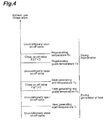
- Fig. 4 is a timing chart showing the relation between the temperature of the exhaust gas and the open/close state of the on-off valve 14.
- the on-off valve 14 is controlled by the processing of the controller 16 as follows.
- the on-off valve 14 is unconditionally closed; if the temperature of the exhaust gas is greater than the heat generating start temperature T L and is equal to or less than the heat generating end guide temperature T Q , the on-off valve 14 is unconditionally opened.
- the on-off valve 14 is closed if the amount of change in exhaust gas temperature, ⁇ T, is more than 0, namely if the temperature of the exhaust gas tends to increase, and the on-off valve 14 is opened if the amount of change in exhaust gas temperature, ⁇ T, is 0 or less, namely, if the temperature of the exhaust gas does not tend to increase. Moreover, if the temperature of the exhaust gas is greater than the heat generating end temperature T G , the on-off valve 14 is unconditionally closed.
- the on-off valve 14 is unconditionally closed. Moreover, if the temperature of the exhaust gas is greater than the regenerating guide temperature T R and is equal to or less than the regenerating temperature T H , the on-off valve 14 is closed if the amount of change in exhaust gas temperature, ⁇ T, is less than 0, namely, the temperature of the exhaust gas tends to decrease, and the on-off valve 14 is opened if the amount of change in exhaust gas temperature, ⁇ T, is 0 or more, namely, the temperature of the exhaust gas does not tend to decrease. Moreover, if the temperature of the exhaust gas is greater than the regenerating temperature T H , the on-off valve 14 is unconditionally opened.
- the on-off valve 14 remains closed if the temperature of the exhaust gas is low, for example, immediately after the engine 2 starts. If the temperature of the exhaust gas increases to reach the heat generating start temperature T L , the on-off valve 14 is opened. Then, because the pressure inside the storage 13 is higher than the pressure inside the reactor 11, NH 3 adsorbed by the storage 13 is fed to the reactor 11 through the pipe 12, and chemically reacts with MgCl 2 in the reactor 11 to be chemically adsorbed, generating heat in the reactor 11. Namely, the exothermic reaction described above occurs. The heat generated in the reactor 11 conducts to the oxidizing catalyst 4 to heat the oxidizing catalyst 4 to the active temperature.
- the on-off valve 14 is closed. Then, because feed of NH 3 from the storage 13 to the reactor 11 is stopped, the exothermic reaction is terminated. Moreover, if the temperature of the exhaust gas reaches the heat generating end guide temperature T Q and the temperature of the exhaust gas does not tend to increase, the on-off valve 14 is kept open; for this reason, the exothermic reaction is continued. Moreover, if the temperature of the exhaust gas further increases to reach the heat generating end temperature T G , the on-off valve 14 is closed irrespective of the amount of change in exhaust gas temperature, ⁇ T; for this reason, the exothermic reaction is terminated.
- the on-off valve 14 is closed until the temperature of the exhaust gas reaches the regenerating temperature T H excluding the case if the temperature of the exhaust gas is greater than the regenerating guide temperature T R and the amount of change in exhaust gas temperature, ⁇ T, is 0 or more; thereby, unintentional occurrence of the reverse reaction (exothermic reaction) can be prevented even if the temperature of the exhaust gas decreases during driving uphill, for example, to fall under a condition not enable regeneration.
- the on-off valve 14 is closed if the temperature of the exhaust gas reaches the heat generating end temperature T G or if the temperature of the exhaust gas reaches the heat generating end guide temperature T Q and the amount of change in exhaust gas temperature, ⁇ T, is more than 0; thereby, the exothermic reaction does not occur beyond necessity, and the charge quantity of NH 3 in the storage 13 can be saved.
- the on-off valve 14 remains closed until the temperature of the exhaust gas reaches the heat generating start temperature T L , activation of the oxidizing catalyst 4 can be promoted without wasting NH 3 in the storage 13.
- the on-off valve 14 is appropriately controlled according to the temperature of the exhaust gas flowing through the oxidizing catalyst 4, the regeneration reaction and the exothermic reaction can be appropriately performed according to the temperature of the exhaust gas. Thereby, loss can be reduced during regeneration and generation of heat, so that the chemical heat storage device 10 can be effectively utilized.
- the present invention is not limited to the embodiment above.
- the temperature sensor 15 directly detecting the temperature of the exhaust gas passing through the oxidizing catalyst 4 has been used in the embodiment above, the target detected by the temperature sensor is not limited to this in particular; the temperature sensor can detect any detection target corresponding to the temperature of the exhaust gas passing through the oxidizing catalyst 4. Examples of such a detection target other than the exhaust gas temperature include the temperature of the oxidizing catalyst 4 as a target object of heating, the temperature of the reactor 11, and the pressure in the reactor 11.
- the procedure shown in Fig. 3 is all performed by the controller 16 in the embodiment above, but the procedure is not limited to such processing in particular.
- the procedures S101 and S102 may not be performed, the procedures S103, S106, and S107 may not be performed, or the procedures S110 to S 112 may not be performed in Fig. 3 .
- at least the procedures S104, S105, S108, S109, and S 113 to S 115 may be performed.
- MgCl 2 has been used as the heat generating material chemically reacted with NH 3 in the embodiment above, other heat generating materials such as CaCl 2 , NiCl 2 , ZnCl 2 , and SrCl 2 can also be used.
- NH 3 has been used as the reaction medium chemically reacted with the heat generating material, the reaction medium is not limited to NH 3 in particular, and H 2 O may be used. In this case, as the heat generating material chemically reacted with H 2 O, CaO, MgO, MnO, CuO, Al 2 O 3 or the like can be used.
- the heat generating start temperature T L , the regenerating guide temperature T R , and the regenerating temperature T H are appropriately determined according to the type and the amount of the reaction medium to be used, the type and the amount of the heat generating material to be used and the like.
- the heat generating end guide temperature T Q and the heat generating end temperature T G are appropriately determined according to the type and the amount of the reaction medium to be used, the type and the amount of the heat generating material to be used, the activation starting temperature of the catalyst as the heating target and the like.
- the embodiment above relates to the chemical heat storage device 10 heating the oxidizing catalyst 4; the chemical heat storage device according to the present invention can be applied to devices heating an exhaust air catalyst disposed in an exhaust air system in diesel engines or gasoline engines, or devices heating other target objects of heating (such as exhaust air pipes) disposed in exhaust air systems.
- 2 ...diesel engine, 3...exhaust air pipe (exhaust air system), 4...oxidizing catalyst (exhaust air catalyst, target object of heating), 10...chemical heat storage device, 11...rector, 12...pipe, 13...storage, 14...on-off valve, 15...temperature sensor (detecting unit, detector), 16...controller (on-off valve control unit, on-off valve controller).
Landscapes
- Engineering & Computer Science (AREA)
- Chemical & Material Sciences (AREA)
- Chemical Kinetics & Catalysis (AREA)
- Mechanical Engineering (AREA)
- General Engineering & Computer Science (AREA)
- Combustion & Propulsion (AREA)
- Toxicology (AREA)
- Health & Medical Sciences (AREA)
- General Chemical & Material Sciences (AREA)
- Physics & Mathematics (AREA)
- Thermal Sciences (AREA)
- Materials Engineering (AREA)
- Exhaust Gas After Treatment (AREA)
- Exhaust Gas Treatment By Means Of Catalyst (AREA)
Abstract
Description
- The present invention relates to a chemical heat storage device which heats a target object of heating disposed in an exhaust air system of an engine.
- As the conventional chemical heat storage devices, for example, a chemical heat storage device described in Patent Literature 1 is known. The chemical heat storage device described in Patent Literature 1 includes a first container disposed upstream of a catalyst body in a gas passage pipe and accommodating an adsorbent which adsorbs/desorbs water as an adsorbed medium to generate/absorb heat, a second container disposed externally to the gas passage pipe and accommodating the adsorbed medium, a communicating pipe communicating the first container with the second container, and an on-off valve disposed halfway of the communicating pipe. If an ignition key is turned on (engine is started), and the on-off valve is opened, the catalyst body is heated and activated by the heat generated accompanying adsorption by the adsorbent. If the catalyst body is sufficiently activated, the adsorbent receiving the heat of the catalyst body is desorbed and be regenerated.
- Patent Literature 1: Japanese Patent Application Laid-Open No.
11-311117 - However, there are the following problems in the conventional techniques. Namely, if the ignition key is turned on, the on-off valve is opened; if the ignition key is turned off, the on-off valve is closed. For this reason, once the ignition key is turned on, the on-off valve remains open until the ignition key is turned off; for this reason, the adsorbed medium goes back and forth between the first container and the second container depending on the temperature of the exhaust gas to perform the exothermic reaction and the regeneration reaction. Accordingly, if the temperature of the exhaust gas tends to decrease during regeneration, for example, the reverse reaction (exothermic reaction) may occur. In generation of heat, the adsorbed medium accommodated in the second container is fed to the first container to continuously react with the adsorbent until the temperature of the exhaust gas reaches the regenerating temperature; for this reason, the amount (charge quantity) of the adsorbed medium in the second container is reduced.
- An object of the present invention is to provide a chemical heat storage device which can appropriately perform the regeneration reaction and the exothermic reaction according to the temperature of the exhaust gas.
- The present invention is a chemical heat storage device which heats a target object of heating disposed in an exhaust air system of an engine, the chemical heat storage device including a reactor disposed around the target object of heating and having a heat generating material which chemically reacts with a reaction medium to generate heat, a storage connected to the reactor through a pipe to store the reaction medium, an on-off valve disposed in the pipe to open/close a flow path for the reaction medium, a detecting unit detecting a detection target corresponding to the temperature of an exhaust gas passing through the target object of heating, and an on-off valve control unit controlling the on-off valve based on a detected value of the detecting unit.
- As described above, in the chemical heat storage device according to the present invention, by detecting the detection target corresponding to the temperature of the exhaust gas passing through the target object of heating to control the on-off valve based on the detected value, the on-off valve can be appropriately controlled according to the temperature of the exhaust gas passing through the target object of heating during regeneration in which the reaction medium and the heat generating material are separated by the heat from the target object of heating and during generation of heat in which heat is generated by the chemical reaction between the reaction medium and the heat generating material. Thereby, the regeneration reaction and the exothermic reaction can be appropriately performed according to the temperature of the exhaust gas. Here, the detection target corresponding to the temperature of the exhaust gas passing through the target object of heating indicates a variety of parameters varying according to the temperature of the exhaust gas, such as the temperature of the exhaust gas itself, the temperature of the target object of heating, the temperature of the reactor, and the pressure of the reactor.
- Preferably, the on-off valve control unit controls the on-off valve such that the on-off valve opens if the detected value of the detecting unit is greater than a first predetermined value at which the reaction medium desorbs from the heat generating material due to heat, controls the on-off valve such that the on-off valve opens if the detected value of the detecting unit is equal to or less than a second predetermined value lower than the first predetermined value, and controls the on-off valve such that the on-off valve closes if the detected value of the detecting unit is equal to or less than the first predetermined value and greater than the second predetermined value.
- As described above, by controlling the on-off valve such that the on-off valve opens if the detected value of the detecting unit is greater than the first predetermined value at which the reaction medium desorbs from the heat generating material due to heat, the on-off valve is closed if the temperature of the exhaust gas is equal to or less than the first predetermined value; accordingly, the occurrence of the reverse reaction (exothermic reaction) during regeneration can be prevented. Moreover, by controlling the on-off valve such that the on-off valve opens if the detected value of the detecting unit is equal to or less than the second predetermined value lower than the first predetermined value, the on-off valve is closed and the exothermic reaction is not performed if the detected value of the detecting unit is greater than the second predetermined value during generation of heat; for this reason, the amount (charge quantity) of the reaction medium stored in the storage can be saved.
- Moreover, preferably, the on-off valve control unit controls the on-off valve such that if the detected value of the detecting unit is greater than the first predetermined value and is equal to or less than a third predetermined value greater than the first predetermined value, the on-off valve closes if the amount of change in the detected value of the detecting unit is less than 0, and the on-off valve opens if the amount of change in the detected value of the detecting unit is 0 or more.
- If the amount of change in the detected value of the detecting unit is less than 0 during regeneration, for example, if the temperature of the exhaust gas tends to decrease, the reverse reaction (exothermic reaction) readily occurs. Then, if the detected value of the detecting unit is equal to or less than the third predetermined value greater than the first predetermined value, by controlling the on-off valve such that the on-off valve closes if the amount of change in the detected value of the detecting unit is less than 0, and the on-off valve opens if the amount of change in the detected value of the detecting unit is 0 or more, the occurrence of the reverse reaction during regeneration can be surely prevented while the regeneration reaction is effectively performed in a wide temperature range.
- Furthermore, preferably, if the detected value of the detecting unit is equal to or less than the second predetermined value and is greater than a fourth predetermined value less than the second predetermined value, the on-off valve control unit controls the on-off valve such that the on-off valve closes if the amount of change in the detected value of the detecting unit is more than 0, and the on-off valve opens if the amount of change in the detected value of the detecting unit is 0 or less.
- If the detected value of the detecting unit is less than the second predetermined value and the amount of change in the detected value of the detecting unit is more than 0, for example, if the temperature of the exhaust gas tends to increase, any particular trouble is not caused even if the exothermic reaction is forcibly terminated. If the detected value of the detecting unit is greater than the fourth predetermined value less than the second predetermined value, by controlling the on-off valve such that the on-off valve closes if the amount of change in the detected value of the detecting unit is more than 0, and the on-off valve opens if the amount of change in the detected value of the detecting unit is 0 or less, the amount of the reaction medium stored in the storage can be more significantly saved.
- Moreover, preferably, the on-off valve control unit controls the on-off valve such that the on-off valve closes if the detected value of the detecting unit is equal to or less than the second predetermined value and the detected value of the detecting unit is equal to or less than a fifth predetermined value at which the target object of heating cannot reach the target temperature even if the reaction medium is chemically reacted with the heat generating material.
- If the temperature of the exhaust gas is excessively low, the target object of heating is difficult to reach the target temperature even by performing the exothermic reaction. Then, by controlling the on-off valve such that the on-off valve closes if the detected value of the detecting unit is equal to or less than the fifth predetermined value at which the target object of heating cannot reach the target temperature even if the reaction medium is chemically reacted with the heat generating material, exothermic reaction does not occur. Accordingly, an efficient exothermic reaction can be performed.
- According to the present invention, the regeneration reaction and the exothermic reaction can be appropriately performed according to the temperature of the exhaust gas. Thereby, the chemical heat storage device can be utilized to the maximum.
-
- [
Fig. 1] Fig. 1 is a schematic configuration showing an exhaust air purifying system including an embodiment of the chemical heat storage device according to the present invention. - [
Fig. 2] Fig. 2 is a schematic configuration showing an embodiment of the chemical heat storage device according to the present invention. - [
Fig. 3] Fig. 3 is a flowchart showing the details of a processing procedure for controlling an on-off valve by a controller shown inFig. 2 . - [
Fig. 4] Fig. 4 is a timing chart showing the relation between the temperature of the exhaust gas and the open/close state of the on-off valve obtained by the control procedure shown inFig. 3 . - Hereinafter, a suitable embodiment of the chemical heat storage device according to the present invention will be described in detail with reference to the drawings.
-
Fig. 1 is a schematic configuration showing an exhaust air purifying system including an embodiment of the chemical heat storage device according to the present invention. In the drawing, an exhaust air purifying system 1 is a system disposed in an exhaust air system of a diesel engine 2 (hereinafter simply referred to as engine 2) in a vehicle and purifying hazardous substances (environmental contaminants) contained in the exhaust gas emitted from theengine 2. - The exhaust air purifying system 1 includes an oxidizing catalyst (DOC: Diesel Oxidation Catalyst) 4, a diesel exhaust air particulate removing filter (DPF: Diesel Particulate Filter) 5, a selective reducing catalyst (SCR: Selective Catalytic Reduction) 6, and an oxidizing catalyst (ASC: Ammonia Slip Catalyst) 7 in sequence from upstream to downstream in the middle of an exhaust air pipe (exhaust air system) 3 connected to the
engine 2. - The oxidizing
catalyst 4 is a catalyst which oxidizes HC, CO and the like contained in the exhaust gas to purify the exhaust gas.DPF 5 is a filter which captures PM contained in the exhaust gas to remove PM. SCR 6 is a catalyst to which urea or ammonia is fed to reduce NOx contained in the exhaust gas to purify the exhaust gas. The oxidizingcatalyst 7 is a catalyst which oxidizes NH3 flowing downstream of the SCR 6. - By the way, there is a temperature region (active temperature) of the exhaust air catalyst such as the oxidizing
catalyst 4 in which the catalyst demonstrate an ability to purify environment contaminants. Accordingly, if the temperature of the exhaust gas is low, for example, immediately after theengine 2 is started, the oxidizingcatalyst 4 needs to be heated to increase the temperature of the oxidizingcatalyst 4 to the active temperature. - Then, the exhaust air purifying system 1 is provided with a chemical
heat storage device 10 according to the present embodiment as shown inFig. 2 . The chemicalheat storage device 10 normally stores the heat (waste heat) of the exhaust gas, and uses the heat when necessary to energy freely heat the oxidizingcatalyst 4. - The chemical
heat storage device 10 includes anannular reactor 11 disposed over the circumference of the oxidizingcatalyst 4, astorage 13 connected to thereactor 11 through apipe 12, and an electromagnetic on-offvalve 14 disposed in thepipe 12. Thereactor 11 is not limited to an annular type in particular; thereactor 11 may be partially disposed on the circumference of the oxidizingcatalyst 4. - The
reactor 11 contains a heat generating material MgCl2 which chemically reacts with a reaction medium NH3 (ammonia) to generate heat. Thestorage 13 stores NH3 in a state of high pressure (for example, 2 to 8 atmospheric pressure) by adsorbing NH3 onto activated carbon. The on-offvalve 14 is a valve which opens/closes the flow path of NH3. - If MgCl2 contained in the
reactor 11 are chemically reacted with NH3 to form chemical adsorption (coordination bond), heat generates in thereactor 11. Namely, the reaction (exothermic reaction) from the left side to the right side in the following reaction equation (A) occurs. In contrast, if the heat (waste heat) of the exhaust gas is given to thereactor 11, MgCl2 and NH3 are separated (desorbed). Namely, the reaction (regeneration reaction) from the right side to the left side in the following reaction equation (A) occurs.
MgCl2(NH3)2 + 4NH3 ⇔ Mg(NH3)6Cl2 + heat ... (A)
- Moreover, the chemical
heat storage device 10 further includes atemperature sensor 15 and acontroller 16. Thetemperature sensor 15 is disposed upstream of the oxidizingcatalyst 4 or inside the oxidizingcatalyst 4 in theexhaust air pipe 3, and detects the temperature of the exhaust gas passing through the oxidizingcatalyst 4. Thecontroller 16 controls the on-offvalve 14 based on the detected value of thetemperature sensor 15. The controller can include a computer. -
Fig. 3 is a flowchart showing the details of the processing procedure for controlling the on-off valve by thecontroller 16. In the drawing, first, it is determined whether the temperature of the exhaust gas detected by thetemperature sensor 15 is equal to or less than a heat generating start temperature TL (fifth predetermined value) (procedure S101). The heat generating start temperature TL is a temperature corresponding to the timing at which increasing of the temperature of the oxidizingcatalyst 4 is started, namely a temperature at which the oxidizingcatalyst 4 cannot reach the active temperature even if MgCl2 and NH3 are chemically reacted, for example, about 150°C. If it is determined that the temperature of the exhaust gas is equal to or less than the heat generating start temperature TL, the on-offvalve 14 is controlled to be closed (procedure S102), and the step returns to procedure S101. - If it is determined that the temperature of the exhaust gas is greater than the heat generating start temperature TL, it is determined whether the temperature of the exhaust gas detected by the
temperature sensor 15 is equal to or less than a heat generating end guide temperature TQ (fourth predetermined value) (procedure S103). The heat generating end guide temperature TQ is a temperature between the heat generating start temperature TL and a heat generating end temperature TG described later, for example, about 200 to 230°C. If it is determined that the temperature of the exhaust gas is equal to or less than the heat generating end guide temperature TQ, the on-offvalve 14 is controlled to be opened (procedure S104), and the step returns to procedure S101. - If it is determined that the temperature of the exhaust gas is greater than the heat generating end guide temperature TQ, it is determined whether the temperature of the exhaust gas detected by the
temperature sensor 15 is equal to or less than a heat generating end temperature TG (second predetermined value) (procedure S105). The heat generating end temperature TG is a temperature corresponding to the temperature immediately before the saturated state (maximum value) of the active temperature of the oxidizingcatalyst 4, for example, about 250°C. - If it is determined that the temperature of the exhaust gas is equal to or less than the heat generating end temperature TG, the amount of change in exhaust gas temperature (the amount of change in the detected value of the temperature sensor 15), Δt, is calculated from the following expression (procedure S106). The amount of change in exhaust gas temperature, ΔT, is calculated, for example, as a rate of variation (differential value) in exhaust gas temperature.

- Subsequently, it is determined whether the amount of change in exhaust gas temperature, ΔT, is more than 0 (procedure S107). If it is determined that the amount of change in exhaust gas temperature, ΔT, is more than 0, the on-off
valve 14 is controlled to be closed (procedure S102), and the step returns to procedure S101. If it is determined that the amount of change in exhaust gas temperature, ΔT, is 0 or less, the on-offvalve 14 is controlled to be opened (procedure S104), and the step returns to procedure S101. - If it is determined at procedure S105 that the temperature of the exhaust gas is greater than the heat generating end temperature TG, it is determined whether the temperature of the exhaust gas detected by the
temperature sensor 15 is equal to or less than a regenerating guide temperature TR (first predetermined value) (procedure S108). The regenerating guide temperature TR is a temperature immediately after NH3 starts desorbing from MgCl2 due to heat, for example, about 265°C. If it is determined that the temperature of the exhaust gas is equal to or less than the regenerating guide temperature TR, the on-offvalve 14 is controlled to be closed (procedure S109), and the step returns to procedure S101. - If it is determined that the temperature of the exhaust gas is greater than the regenerating guide temperature TR, it is determined whether the temperature of the exhaust gas detected by the
temperature sensor 15 is equal to or less than a regenerating temperature TH (third predetermined value) (procedure S110). The regenerating temperature TH is a temperature at which NH3 completely desorbs from MgCl2 due to heat, for example, about 290°C. - If it is determined that the temperature of the exhaust gas is equal to or less than the regenerating temperature TH, the amount of change in exhaust gas temperature, ΔT, is calculated from the above expression (B) in the same manner as in procedure S106 (procedure S111). Subsequently, it is determined whether the amount of change in exhaust gas temperature, ΔT, is less than 0 (procedure S 112). If it is determined that the amount of change in exhaust gas temperature, ΔT, is less than 0, the on-off
valve 14 is controlled to be closed (procedure S109), and the step returns to procedure S101. If it is determined that the amount of change in exhaust gas temperature, ΔT, is 0 or more, the on-offvalve 14 is controlled to be opened (procedure S113). - If it is determined that the temperature of the exhaust gas is greater than the regenerating temperature TH in procedure S110, the on-off
valve 14 is controlled to be opened (procedure S113). - After the procedure S113 is performed, it is determined whether the regeneration reaction is terminated or not (procedure S 114). The termination of the regeneration reaction can be determined from the integration value of the temperature of the exhaust gas and the regeneration time, or can be determined by detecting the pressure inside the
storage 13, for example. If it is determined that the regeneration reaction is terminated, the on-offvalve 14 is controlled to be closed (procedure S115), and the processing is terminated. - In the above procedure, the
temperature sensor 15 is configured as a detecting unit (detector) detecting the temperature of the exhaust gas passing through the target object of heating (oxidizing catalyst 4). Thecontroller 16 is configured as an on-off valve control unit (on-off valve controller) controlling the on-offvalve 14 based on the detected value of the detecting unit. -
Fig. 4 is a timing chart showing the relation between the temperature of the exhaust gas and the open/close state of the on-offvalve 14. In the drawing, the on-offvalve 14 is controlled by the processing of thecontroller 16 as follows. - Namely, during generation of heat, if the temperature of the exhaust gas is equal to or less than the heat generating start temperature TL, the on-off
valve 14 is unconditionally closed; if the temperature of the exhaust gas is greater than the heat generating start temperature TL and is equal to or less than the heat generating end guide temperature TQ, the on-offvalve 14 is unconditionally opened. Moreover, if the temperature of the exhaust gas is greater than the heat generating end guide temperature TQ and is equal to or less than the heat generating end temperature TG, the on-offvalve 14 is closed if the amount of change in exhaust gas temperature, ΔT, is more than 0, namely if the temperature of the exhaust gas tends to increase, and the on-offvalve 14 is opened if the amount of change in exhaust gas temperature, ΔT, is 0 or less, namely, if the temperature of the exhaust gas does not tend to increase. Moreover, if the temperature of the exhaust gas is greater than the heat generating end temperature TG, the on-offvalve 14 is unconditionally closed. - In contrast, during regeneration, if the temperature of the exhaust gas is equal to or less than the regenerating guide temperature TR, the on-off
valve 14 is unconditionally closed. Moreover, if the temperature of the exhaust gas is greater than the regenerating guide temperature TR and is equal to or less than the regenerating temperature TH, the on-offvalve 14 is closed if the amount of change in exhaust gas temperature, ΔT, is less than 0, namely, the temperature of the exhaust gas tends to decrease, and the on-offvalve 14 is opened if the amount of change in exhaust gas temperature, ΔT, is 0 or more, namely, the temperature of the exhaust gas does not tend to decrease. Moreover, if the temperature of the exhaust gas is greater than the regenerating temperature TH, the on-offvalve 14 is unconditionally opened. - In the exhaust air purifying system 1 including the chemical
heat storage device 10 described above, the on-offvalve 14 remains closed if the temperature of the exhaust gas is low, for example, immediately after theengine 2 starts. If the temperature of the exhaust gas increases to reach the heat generating start temperature TL, the on-offvalve 14 is opened. Then, because the pressure inside thestorage 13 is higher than the pressure inside thereactor 11, NH3 adsorbed by thestorage 13 is fed to thereactor 11 through thepipe 12, and chemically reacts with MgCl2 in thereactor 11 to be chemically adsorbed, generating heat in thereactor 11. Namely, the exothermic reaction described above occurs. The heat generated in thereactor 11 conducts to the oxidizingcatalyst 4 to heat the oxidizingcatalyst 4 to the active temperature. - Then, if the temperature of the exhaust gas further increases to reach the heat generating end guide temperature TQ, and if the amount of change in exhaust gas temperature, ΔT, is more than 0 and the temperature of the exhaust gas tends to increase, the on-off
valve 14 is closed. Then, because feed of NH3 from thestorage 13 to thereactor 11 is stopped, the exothermic reaction is terminated. Moreover, if the temperature of the exhaust gas reaches the heat generating end guide temperature TQ and the temperature of the exhaust gas does not tend to increase, the on-offvalve 14 is kept open; for this reason, the exothermic reaction is continued. Moreover, if the temperature of the exhaust gas further increases to reach the heat generating end temperature TG, the on-offvalve 14 is closed irrespective of the amount of change in exhaust gas temperature, ΔT; for this reason, the exothermic reaction is terminated. - Subsequently, if the temperature of the exhaust gas further increases to reach the regenerating guide temperature TR, the heat (waste heat) of the exhaust gas is given from the oxidizing
catalyst 4 to thereactor 11 to separate MgCl2 from NH3, causing the regeneration reaction described above. At this time, if the amount of change in exhaust gas temperature, ΔT, is less than 0 and the temperature of the exhaust gas tends to decrease, the on-offvalve 14 remains closed. - In contrast, if the amount of change in exhaust gas temperature, ΔT, is 0 or more and the temperature of the exhaust gas does not tend to decrease, the on-off
valve 14 is opened. Then, because the pressure of thereactor 11 is higher than the pressure of thestorage 13, NH3 separated from MgCl2 passes through thepipe 12 to return to thestorage 13; NH3 is adsorbed by activated carbon to be recovered. Moreover, if the temperature of the exhaust gas further increases to reach the regenerating temperature TH, separation (regeneration) of MgCl2 and NH3 is promoted to open the on-offvalve 14 irrespective of the amount of change in exhaust gas temperature, ΔT; for this reason, NH3 is recovered in thestorage 13. - Subsequently, if the regeneration reaction is terminated, the on-off
valve 14 is closed; for this reason, recovery of NH3 to thestorage 13 is terminated, and NH3 is stored (charged) in thestorage 13 under high pressure. - As described above, in the present embodiment, during regeneration, the on-off
valve 14 is closed until the temperature of the exhaust gas reaches the regenerating temperature TH excluding the case if the temperature of the exhaust gas is greater than the regenerating guide temperature TR and the amount of change in exhaust gas temperature, ΔT, is 0 or more; thereby, unintentional occurrence of the reverse reaction (exothermic reaction) can be prevented even if the temperature of the exhaust gas decreases during driving uphill, for example, to fall under a condition not enable regeneration. - In contrast, during generation of heat, the on-off
valve 14 is closed if the temperature of the exhaust gas reaches the heat generating end temperature TG or if the temperature of the exhaust gas reaches the heat generating end guide temperature TQ and the amount of change in exhaust gas temperature, ΔT, is more than 0; thereby, the exothermic reaction does not occur beyond necessity, and the charge quantity of NH3 in thestorage 13 can be saved. - Moreover, if the temperature of the exhaust gas is excessively low and the exothermic reaction occurs, the temperature of the exhaust gas does not reach the active temperature of the oxidizing
catalyst 4, and the oxidizingcatalyst 4 is barely activated. In the present embodiment, however, the on-offvalve 14 remains closed until the temperature of the exhaust gas reaches the heat generating start temperature TL, activation of the oxidizingcatalyst 4 can be promoted without wasting NH3 in thestorage 13. - As described above, because the on-off
valve 14 is appropriately controlled according to the temperature of the exhaust gas flowing through the oxidizingcatalyst 4, the regeneration reaction and the exothermic reaction can be appropriately performed according to the temperature of the exhaust gas. Thereby, loss can be reduced during regeneration and generation of heat, so that the chemicalheat storage device 10 can be effectively utilized. - It should be noted that the present invention is not limited to the embodiment above. For example, the
temperature sensor 15 directly detecting the temperature of the exhaust gas passing through the oxidizingcatalyst 4 has been used in the embodiment above, the target detected by the temperature sensor is not limited to this in particular; the temperature sensor can detect any detection target corresponding to the temperature of the exhaust gas passing through the oxidizingcatalyst 4. Examples of such a detection target other than the exhaust gas temperature include the temperature of the oxidizingcatalyst 4 as a target object of heating, the temperature of thereactor 11, and the pressure in thereactor 11. - Moreover, the procedure shown in
Fig. 3 is all performed by thecontroller 16 in the embodiment above, but the procedure is not limited to such processing in particular. For example, the procedures S101 and S102 may not be performed, the procedures S103, S106, and S107 may not be performed, or the procedures S110 toS 112 may not be performed inFig. 3 . In short, inFig. 3 , at least the procedures S104, S105, S108, S109, and S 113 toS 115 may be performed. - Moreover, although MgCl2 has been used as the heat generating material chemically reacted with NH3 in the embodiment above, other heat generating materials such as CaCl2, NiCl2, ZnCl2, and SrCl2 can also be used. Moreover, although NH3 has been used as the reaction medium chemically reacted with the heat generating material, the reaction medium is not limited to NH3 in particular, and H2O may be used. In this case, as the heat generating material chemically reacted with H2O, CaO, MgO, MnO, CuO, Al2O3 or the like can be used. At this time, the heat generating start temperature TL, the regenerating guide temperature TR, and the regenerating temperature TH are appropriately determined according to the type and the amount of the reaction medium to be used, the type and the amount of the heat generating material to be used and the like. The heat generating end guide temperature TQ and the heat generating end temperature TG are appropriately determined according to the type and the amount of the reaction medium to be used, the type and the amount of the heat generating material to be used, the activation starting temperature of the catalyst as the heating target and the like.
- Moreover, the embodiment above relates to the chemical
heat storage device 10 heating the oxidizingcatalyst 4; the chemical heat storage device according to the present invention can be applied to devices heating an exhaust air catalyst disposed in an exhaust air system in diesel engines or gasoline engines, or devices heating other target objects of heating (such as exhaust air pipes) disposed in exhaust air systems. - 2...diesel engine, 3...exhaust air pipe (exhaust air system), 4...oxidizing catalyst (exhaust air catalyst, target object of heating), 10...chemical heat storage device, 11...rector, 12...pipe, 13...storage, 14...on-off valve, 15...temperature sensor (detecting unit, detector), 16...controller (on-off valve control unit, on-off valve controller).
Claims (5)
- A chemical heat storage device heating a target object of heating disposed in an exhaust air system of an engine, the chemical heat storage device comprising
a reactor disposed around the target object of heating, the reactor having a heat generating material which chemically reacts with a reaction medium to generate heat,
a storage connected to the reactor through a pipe to store the reaction medium,
an on-off valve disposed in the pipe to open and close a flow path for the reaction medium,
a detector detecting a detection target corresponding to a temperature of an exhaust gas passing through the target object of heating, and
an on-off valve controller controlling the on-off valve based on a detected value of the detector. - The chemical heat storage device according to claim 1, wherein the on-off valve controller controls the on-off valve such that the on-off valve opens if a detected value of the detector is greater than a first predetermined value at which the reaction medium desorbs from the heat generating material due to heat, and controls the on-off valve such that the on-off valve opens if the detected value of the detector is equal to or less than a second predetermined value lower than the first predetermined value, and controls the on-off valve such that the on-off valve closes if the detected value of the detector is equal to or less than the first predetermined value and is greater than the second predetermined value.
- The chemical heat storage device according to claim 2, wherein the on-off valve controller controls the on-off valve such that if the detected value of the detector is greater than the first predetermined value and the detected value of the detector is equal to or less than a third predetermined value greater than the first predetermined value, the on-off valve closes if the amount of change in the detected value of the detector is less than 0, and the on-off valve opens if the amount of change in the detected value of the detector is 0 or more.
- The chemical heat storage device according to claim 2 or 3, wherein the on-off valve controller controls the on-off valve such that if the detected value of the detector is equal to or less than the second predetermined value and the detected value of the detector is greater than a fourth predetermined value lower than the second predetermined value, the on-off valve closes if the amount of change in the detected value of the detector is more than 0, and the on-off valve opens if the amount of change in the detected value of the detector is 0 or less.
- The chemical heat storage device according to any one of claims 2 to 4, wherein the on-off valve controller controls the on-off valve such that the on-off valve closes if the detected value of the detector is equal to or less than the second predetermined value and the detected value of the detector is equal to or less than a fifth predetermined value at which the target object of heating cannot reach a target temperature even if the reaction medium is chemically reacted with the heat generating material.
Applications Claiming Priority (2)
| Application Number | Priority Date | Filing Date | Title |
|---|---|---|---|
| JP2013140772A JP6111905B2 (en) | 2013-07-04 | 2013-07-04 | Chemical heat storage device |
| PCT/JP2014/065142 WO2015001910A1 (en) | 2013-07-04 | 2014-06-06 | Chemical heat storage device |
Publications (3)
| Publication Number | Publication Date |
|---|---|
| EP3018316A1 true EP3018316A1 (en) | 2016-05-11 |
| EP3018316A4 EP3018316A4 (en) | 2017-03-15 |
| EP3018316B1 EP3018316B1 (en) | 2018-04-11 |
Family
ID=52143496
Family Applications (1)
| Application Number | Title | Priority Date | Filing Date |
|---|---|---|---|
| EP14820349.0A Not-in-force EP3018316B1 (en) | 2013-07-04 | 2014-06-06 | Chemical heat storage device |
Country Status (4)
| Country | Link |
|---|---|
| US (1) | US9726060B2 (en) |
| EP (1) | EP3018316B1 (en) |
| JP (1) | JP6111905B2 (en) |
| WO (1) | WO2015001910A1 (en) |
Families Citing this family (2)
| Publication number | Priority date | Publication date | Assignee | Title |
|---|---|---|---|---|
| JP2016200321A (en) * | 2015-04-09 | 2016-12-01 | 株式会社豊田自動織機 | Chemical heat storage device |
| JP7490341B2 (en) * | 2019-06-24 | 2024-05-27 | 住友重機械工業株式会社 | Chemical heat storage device and method for storing heat in chemical heat storage material |
Family Cites Families (12)
| Publication number | Priority date | Publication date | Assignee | Title |
|---|---|---|---|---|
| JPH04347320A (en) * | 1991-05-21 | 1992-12-02 | Toyota Motor Corp | Catalyst heating device |
| JPH0913960A (en) * | 1995-06-28 | 1997-01-14 | Nippondenso Co Ltd | Combine system of catalyst heating device and cooling device |
| JPH11311117A (en) * | 1998-04-28 | 1999-11-09 | Denso Corp | Catalyst heating device |
| JP2001289039A (en) * | 2000-04-06 | 2001-10-19 | Nissan Motor Co Ltd | Exhaust gas purification device for internal combustion engine |
| US6951099B2 (en) * | 2001-04-03 | 2005-10-04 | John Dickau | Heated insulated catalytic converter with air cooling |
| JP5381861B2 (en) | 2010-03-29 | 2014-01-08 | 株式会社デンソー | Chemical heat storage device |
| DE112011100535B4 (en) * | 2011-03-22 | 2022-02-24 | Toyota Jidosha Kabushiki Kaisha | Heat storage device for a vehicle |
| JP5698056B2 (en) * | 2011-03-31 | 2015-04-08 | 株式会社豊田中央研究所 | Chemical heat storage device |
| KR20130024079A (en) * | 2011-08-30 | 2013-03-08 | 현대자동차주식회사 | Solid scr system and heating method of solid reductant using the same |
| KR101305199B1 (en) * | 2011-12-09 | 2013-09-12 | 한양대학교 에리카산학협력단 | Heat storage device of vehicle |
| US9228472B2 (en) * | 2013-06-19 | 2016-01-05 | Ford Global Technologies, Llc | System for thermal management of a vehicle and method for vehicle cold start |
| JP2015004457A (en) * | 2013-06-19 | 2015-01-08 | 株式会社豊田自動織機 | Chemical heat storage device |
-
2013
- 2013-07-04 JP JP2013140772A patent/JP6111905B2/en not_active Expired - Fee Related
-
2014
- 2014-06-06 US US14/902,372 patent/US9726060B2/en not_active Expired - Fee Related
- 2014-06-06 WO PCT/JP2014/065142 patent/WO2015001910A1/en not_active Ceased
- 2014-06-06 EP EP14820349.0A patent/EP3018316B1/en not_active Not-in-force
Non-Patent Citations (1)
| Title |
|---|
| See references of WO2015001910A1 * |
Also Published As
| Publication number | Publication date |
|---|---|
| EP3018316B1 (en) | 2018-04-11 |
| US20160369675A1 (en) | 2016-12-22 |
| JP2015014234A (en) | 2015-01-22 |
| WO2015001910A1 (en) | 2015-01-08 |
| JP6111905B2 (en) | 2017-04-12 |
| US9726060B2 (en) | 2017-08-08 |
| EP3018316A4 (en) | 2017-03-15 |
Similar Documents
| Publication | Publication Date | Title |
|---|---|---|
| RU2736984C2 (en) | Method and device for operation of exhaust gas neutralization system | |
| US9476341B2 (en) | Exhaust treatment system that generates debounce duration for NOx sensor offset | |
| EP2925978B1 (en) | Method and apparatus to control selective catalytic reduction (scr) catalyst ammonia slip during high temperature transition phases | |
| USRE48658E1 (en) | Exhaust gas purification apparatus for an internal combustion engine | |
| WO2010065963A2 (en) | Apparatus, system, and method for estimating an nox conversion efficiency of a selective catalytic reduction catalyst | |
| CN104379889B (en) | Exhaust purification device for internal combustion engines | |
| US20130213008A1 (en) | Method and system for improving the robustness of aftertreatment systems | |
| JP5348539B2 (en) | Exhaust gas purification device for internal combustion engine | |
| JP5954123B2 (en) | Exhaust gas purification system | |
| KR102383213B1 (en) | Exhaust gas purification device of vehicle and control method thereof | |
| EP3018316B1 (en) | Chemical heat storage device | |
| US20130014493A1 (en) | System for purifying exhaust gas and method for controlling the same | |
| JP6070402B2 (en) | Chemical heat storage device | |
| JP6102527B2 (en) | Chemical heat storage device | |
| EP2806126B1 (en) | Exhaust gas purification apparatus for internal combustion engine | |
| JP6131777B2 (en) | Chemical heat storage device | |
| JP2007100572A (en) | Exhaust gas purification device for internal combustion engine | |
| EP3217133A1 (en) | Chemical heat storage apparatus | |
| JP2010261387A (en) | Exhaust gas purification device for internal combustion engine | |
| EP3104108A1 (en) | Chemical thermal storage device | |
| JP2015183635A (en) | Chemical heat storage device | |
| WO2016163289A1 (en) | Chemical heat-storage device | |
| CN110118116A (en) | Method and system for exhaust gas treatment device | |
| CN108332918B (en) | Self-checking method of vehicle tail gas treatment system | |
| JP2014066162A (en) | Exhaust emission control device |
Legal Events
| Date | Code | Title | Description |
|---|---|---|---|
| PUAI | Public reference made under article 153(3) epc to a published international application that has entered the european phase |
Free format text: ORIGINAL CODE: 0009012 |
|
| 17P | Request for examination filed |
Effective date: 20151214 |
|
| AK | Designated contracting states |
Kind code of ref document: A1 Designated state(s): AL AT BE BG CH CY CZ DE DK EE ES FI FR GB GR HR HU IE IS IT LI LT LU LV MC MK MT NL NO PL PT RO RS SE SI SK SM TR |
|
| AX | Request for extension of the european patent |
Extension state: BA ME |
|
| DAX | Request for extension of the european patent (deleted) | ||
| A4 | Supplementary search report drawn up and despatched |
Effective date: 20170210 |
|
| RIC1 | Information provided on ipc code assigned before grant |
Ipc: F01N 3/24 20060101ALI20170206BHEP Ipc: F01N 3/08 20060101ALI20170206BHEP Ipc: F01N 3/20 20060101ALI20170206BHEP Ipc: F28D 20/00 20060101ALI20170206BHEP Ipc: F01N 3/10 20060101ALI20170206BHEP Ipc: F01N 3/26 20060101ALI20170206BHEP Ipc: F01N 5/02 20060101AFI20170206BHEP |
|
| GRAP | Despatch of communication of intention to grant a patent |
Free format text: ORIGINAL CODE: EPIDOSNIGR1 |
|
| RIC1 | Information provided on ipc code assigned before grant |
Ipc: F01N 3/24 20060101ALI20170801BHEP Ipc: F01N 3/20 20060101ALI20170801BHEP Ipc: F01N 5/02 20060101AFI20170801BHEP Ipc: F01N 3/08 20060101ALI20170801BHEP Ipc: F01N 3/10 20060101ALI20170801BHEP Ipc: F28D 20/00 20060101ALI20170801BHEP Ipc: F01N 3/26 20060101ALI20170801BHEP |
|
| INTG | Intention to grant announced |
Effective date: 20170907 |
|
| RIN1 | Information on inventor provided before grant (corrected) |
Inventor name: MORI, KENJI Inventor name: HARIU, SATOSHI Inventor name: YAMASAKI, TAKAFUMI |
|
| GRAS | Grant fee paid |
Free format text: ORIGINAL CODE: EPIDOSNIGR3 |
|
| GRAA | (expected) grant |
Free format text: ORIGINAL CODE: 0009210 |
|
| AK | Designated contracting states |
Kind code of ref document: B1 Designated state(s): AL AT BE BG CH CY CZ DE DK EE ES FI FR GB GR HR HU IE IS IT LI LT LU LV MC MK MT NL NO PL PT RO RS SE SI SK SM TR |
|
| REG | Reference to a national code |
Ref country code: GB Ref legal event code: FG4D |
|
| REG | Reference to a national code |
Ref country code: CH Ref legal event code: EP |
|
| REG | Reference to a national code |
Ref country code: AT Ref legal event code: REF Ref document number: 988259 Country of ref document: AT Kind code of ref document: T Effective date: 20180415 |
|
| REG | Reference to a national code |
Ref country code: IE Ref legal event code: FG4D |
|
| REG | Reference to a national code |
Ref country code: DE Ref legal event code: R096 Ref document number: 602014023871 Country of ref document: DE |
|
| REG | Reference to a national code |
Ref country code: FR Ref legal event code: PLFP Year of fee payment: 5 |
|
| REG | Reference to a national code |
Ref country code: NL Ref legal event code: MP Effective date: 20180411 |
|
| REG | Reference to a national code |
Ref country code: LT Ref legal event code: MG4D |
|
| PGFP | Annual fee paid to national office [announced via postgrant information from national office to epo] |
Ref country code: FR Payment date: 20180625 Year of fee payment: 5 |
|
| PG25 | Lapsed in a contracting state [announced via postgrant information from national office to epo] |
Ref country code: NL Free format text: LAPSE BECAUSE OF FAILURE TO SUBMIT A TRANSLATION OF THE DESCRIPTION OR TO PAY THE FEE WITHIN THE PRESCRIBED TIME-LIMIT Effective date: 20180411 |
|
| PG25 | Lapsed in a contracting state [announced via postgrant information from national office to epo] |
Ref country code: PL Free format text: LAPSE BECAUSE OF FAILURE TO SUBMIT A TRANSLATION OF THE DESCRIPTION OR TO PAY THE FEE WITHIN THE PRESCRIBED TIME-LIMIT Effective date: 20180411 Ref country code: NO Free format text: LAPSE BECAUSE OF FAILURE TO SUBMIT A TRANSLATION OF THE DESCRIPTION OR TO PAY THE FEE WITHIN THE PRESCRIBED TIME-LIMIT Effective date: 20180711 Ref country code: ES Free format text: LAPSE BECAUSE OF FAILURE TO SUBMIT A TRANSLATION OF THE DESCRIPTION OR TO PAY THE FEE WITHIN THE PRESCRIBED TIME-LIMIT Effective date: 20180411 Ref country code: LT Free format text: LAPSE BECAUSE OF FAILURE TO SUBMIT A TRANSLATION OF THE DESCRIPTION OR TO PAY THE FEE WITHIN THE PRESCRIBED TIME-LIMIT Effective date: 20180411 Ref country code: AL Free format text: LAPSE BECAUSE OF FAILURE TO SUBMIT A TRANSLATION OF THE DESCRIPTION OR TO PAY THE FEE WITHIN THE PRESCRIBED TIME-LIMIT Effective date: 20180411 Ref country code: BG Free format text: LAPSE BECAUSE OF FAILURE TO SUBMIT A TRANSLATION OF THE DESCRIPTION OR TO PAY THE FEE WITHIN THE PRESCRIBED TIME-LIMIT Effective date: 20180711 Ref country code: SE Free format text: LAPSE BECAUSE OF FAILURE TO SUBMIT A TRANSLATION OF THE DESCRIPTION OR TO PAY THE FEE WITHIN THE PRESCRIBED TIME-LIMIT Effective date: 20180411 Ref country code: FI Free format text: LAPSE BECAUSE OF FAILURE TO SUBMIT A TRANSLATION OF THE DESCRIPTION OR TO PAY THE FEE WITHIN THE PRESCRIBED TIME-LIMIT Effective date: 20180411 |
|
| PGFP | Annual fee paid to national office [announced via postgrant information from national office to epo] |
Ref country code: DE Payment date: 20180629 Year of fee payment: 5 |
|
| PG25 | Lapsed in a contracting state [announced via postgrant information from national office to epo] |
Ref country code: LV Free format text: LAPSE BECAUSE OF FAILURE TO SUBMIT A TRANSLATION OF THE DESCRIPTION OR TO PAY THE FEE WITHIN THE PRESCRIBED TIME-LIMIT Effective date: 20180411 Ref country code: RS Free format text: LAPSE BECAUSE OF FAILURE TO SUBMIT A TRANSLATION OF THE DESCRIPTION OR TO PAY THE FEE WITHIN THE PRESCRIBED TIME-LIMIT Effective date: 20180411 Ref country code: HR Free format text: LAPSE BECAUSE OF FAILURE TO SUBMIT A TRANSLATION OF THE DESCRIPTION OR TO PAY THE FEE WITHIN THE PRESCRIBED TIME-LIMIT Effective date: 20180411 Ref country code: GR Free format text: LAPSE BECAUSE OF FAILURE TO SUBMIT A TRANSLATION OF THE DESCRIPTION OR TO PAY THE FEE WITHIN THE PRESCRIBED TIME-LIMIT Effective date: 20180712 |
|
| REG | Reference to a national code |
Ref country code: AT Ref legal event code: MK05 Ref document number: 988259 Country of ref document: AT Kind code of ref document: T Effective date: 20180411 |
|
| PG25 | Lapsed in a contracting state [announced via postgrant information from national office to epo] |
Ref country code: PT Free format text: LAPSE BECAUSE OF FAILURE TO SUBMIT A TRANSLATION OF THE DESCRIPTION OR TO PAY THE FEE WITHIN THE PRESCRIBED TIME-LIMIT Effective date: 20180813 |
|
| REG | Reference to a national code |
Ref country code: DE Ref legal event code: R097 Ref document number: 602014023871 Country of ref document: DE |
|
| PG25 | Lapsed in a contracting state [announced via postgrant information from national office to epo] |
Ref country code: AT Free format text: LAPSE BECAUSE OF FAILURE TO SUBMIT A TRANSLATION OF THE DESCRIPTION OR TO PAY THE FEE WITHIN THE PRESCRIBED TIME-LIMIT Effective date: 20180411 Ref country code: DK Free format text: LAPSE BECAUSE OF FAILURE TO SUBMIT A TRANSLATION OF THE DESCRIPTION OR TO PAY THE FEE WITHIN THE PRESCRIBED TIME-LIMIT Effective date: 20180411 Ref country code: SK Free format text: LAPSE BECAUSE OF FAILURE TO SUBMIT A TRANSLATION OF THE DESCRIPTION OR TO PAY THE FEE WITHIN THE PRESCRIBED TIME-LIMIT Effective date: 20180411 Ref country code: RO Free format text: LAPSE BECAUSE OF FAILURE TO SUBMIT A TRANSLATION OF THE DESCRIPTION OR TO PAY THE FEE WITHIN THE PRESCRIBED TIME-LIMIT Effective date: 20180411 Ref country code: CZ Free format text: LAPSE BECAUSE OF FAILURE TO SUBMIT A TRANSLATION OF THE DESCRIPTION OR TO PAY THE FEE WITHIN THE PRESCRIBED TIME-LIMIT Effective date: 20180411 Ref country code: EE Free format text: LAPSE BECAUSE OF FAILURE TO SUBMIT A TRANSLATION OF THE DESCRIPTION OR TO PAY THE FEE WITHIN THE PRESCRIBED TIME-LIMIT Effective date: 20180411 |
|
| REG | Reference to a national code |
Ref country code: CH Ref legal event code: PL |
|
| PLBE | No opposition filed within time limit |
Free format text: ORIGINAL CODE: 0009261 |
|
| STAA | Information on the status of an ep patent application or granted ep patent |
Free format text: STATUS: NO OPPOSITION FILED WITHIN TIME LIMIT |
|
| PG25 | Lapsed in a contracting state [announced via postgrant information from national office to epo] |
Ref country code: SM Free format text: LAPSE BECAUSE OF FAILURE TO SUBMIT A TRANSLATION OF THE DESCRIPTION OR TO PAY THE FEE WITHIN THE PRESCRIBED TIME-LIMIT Effective date: 20180411 Ref country code: IT Free format text: LAPSE BECAUSE OF FAILURE TO SUBMIT A TRANSLATION OF THE DESCRIPTION OR TO PAY THE FEE WITHIN THE PRESCRIBED TIME-LIMIT Effective date: 20180411 |
|
| REG | Reference to a national code |
Ref country code: BE Ref legal event code: MM Effective date: 20180630 |
|
| 26N | No opposition filed |
Effective date: 20190114 |
|
| REG | Reference to a national code |
Ref country code: IE Ref legal event code: MM4A |
|
| GBPC | Gb: european patent ceased through non-payment of renewal fee |
Effective date: 20180711 |
|
| PG25 | Lapsed in a contracting state [announced via postgrant information from national office to epo] |
Ref country code: MC Free format text: LAPSE BECAUSE OF FAILURE TO SUBMIT A TRANSLATION OF THE DESCRIPTION OR TO PAY THE FEE WITHIN THE PRESCRIBED TIME-LIMIT Effective date: 20180411 Ref country code: LU Free format text: LAPSE BECAUSE OF NON-PAYMENT OF DUE FEES Effective date: 20180606 |
|
| PG25 | Lapsed in a contracting state [announced via postgrant information from national office to epo] |
Ref country code: LI Free format text: LAPSE BECAUSE OF NON-PAYMENT OF DUE FEES Effective date: 20180630 Ref country code: GB Free format text: LAPSE BECAUSE OF NON-PAYMENT OF DUE FEES Effective date: 20180711 Ref country code: IE Free format text: LAPSE BECAUSE OF NON-PAYMENT OF DUE FEES Effective date: 20180606 Ref country code: CH Free format text: LAPSE BECAUSE OF NON-PAYMENT OF DUE FEES Effective date: 20180630 |
|
| PG25 | Lapsed in a contracting state [announced via postgrant information from national office to epo] |
Ref country code: SI Free format text: LAPSE BECAUSE OF FAILURE TO SUBMIT A TRANSLATION OF THE DESCRIPTION OR TO PAY THE FEE WITHIN THE PRESCRIBED TIME-LIMIT Effective date: 20180411 Ref country code: BE Free format text: LAPSE BECAUSE OF NON-PAYMENT OF DUE FEES Effective date: 20180630 |
|
| REG | Reference to a national code |
Ref country code: DE Ref legal event code: R119 Ref document number: 602014023871 Country of ref document: DE |
|
| PG25 | Lapsed in a contracting state [announced via postgrant information from national office to epo] |
Ref country code: MT Free format text: LAPSE BECAUSE OF NON-PAYMENT OF DUE FEES Effective date: 20180606 |
|
| PG25 | Lapsed in a contracting state [announced via postgrant information from national office to epo] |
Ref country code: TR Free format text: LAPSE BECAUSE OF FAILURE TO SUBMIT A TRANSLATION OF THE DESCRIPTION OR TO PAY THE FEE WITHIN THE PRESCRIBED TIME-LIMIT Effective date: 20180411 |
|
| PG25 | Lapsed in a contracting state [announced via postgrant information from national office to epo] |
Ref country code: DE Free format text: LAPSE BECAUSE OF NON-PAYMENT OF DUE FEES Effective date: 20200101 |
|
| PG25 | Lapsed in a contracting state [announced via postgrant information from national office to epo] |
Ref country code: CY Free format text: LAPSE BECAUSE OF FAILURE TO SUBMIT A TRANSLATION OF THE DESCRIPTION OR TO PAY THE FEE WITHIN THE PRESCRIBED TIME-LIMIT Effective date: 20180411 Ref country code: FR Free format text: LAPSE BECAUSE OF NON-PAYMENT OF DUE FEES Effective date: 20190630 Ref country code: HU Free format text: LAPSE BECAUSE OF FAILURE TO SUBMIT A TRANSLATION OF THE DESCRIPTION OR TO PAY THE FEE WITHIN THE PRESCRIBED TIME-LIMIT; INVALID AB INITIO Effective date: 20140606 Ref country code: MK Free format text: LAPSE BECAUSE OF NON-PAYMENT OF DUE FEES Effective date: 20180411 |
|
| PG25 | Lapsed in a contracting state [announced via postgrant information from national office to epo] |
Ref country code: IS Free format text: LAPSE BECAUSE OF FAILURE TO SUBMIT A TRANSLATION OF THE DESCRIPTION OR TO PAY THE FEE WITHIN THE PRESCRIBED TIME-LIMIT Effective date: 20180811 |