EP3017921A1 - Robot, arm structure for robot, and actuating device - Google Patents
Robot, arm structure for robot, and actuating device Download PDFInfo
- Publication number
- EP3017921A1 EP3017921A1 EP13888568.6A EP13888568A EP3017921A1 EP 3017921 A1 EP3017921 A1 EP 3017921A1 EP 13888568 A EP13888568 A EP 13888568A EP 3017921 A1 EP3017921 A1 EP 3017921A1
- Authority
- EP
- European Patent Office
- Prior art keywords
- driving
- hollow
- robot
- arm
- shafts
- Prior art date
- Legal status (The legal status is an assumption and is not a legal conclusion. Google has not performed a legal analysis and makes no representation as to the accuracy of the status listed.)
- Granted
Links
Images


Classifications
-
- B—PERFORMING OPERATIONS; TRANSPORTING
- B25—HAND TOOLS; PORTABLE POWER-DRIVEN TOOLS; MANIPULATORS
- B25J—MANIPULATORS; CHAMBERS PROVIDED WITH MANIPULATION DEVICES
- B25J9/00—Program-controlled manipulators
- B25J9/10—Program-controlled manipulators characterised by positioning means for manipulator elements
- B25J9/102—Gears specially adapted therefor, e.g. reduction gears
-
- B—PERFORMING OPERATIONS; TRANSPORTING
- B25—HAND TOOLS; PORTABLE POWER-DRIVEN TOOLS; MANIPULATORS
- B25J—MANIPULATORS; CHAMBERS PROVIDED WITH MANIPULATION DEVICES
- B25J17/00—Joints
-
- B—PERFORMING OPERATIONS; TRANSPORTING
- B25—HAND TOOLS; PORTABLE POWER-DRIVEN TOOLS; MANIPULATORS
- B25J—MANIPULATORS; CHAMBERS PROVIDED WITH MANIPULATION DEVICES
- B25J18/00—Arms
-
- B—PERFORMING OPERATIONS; TRANSPORTING
- B25—HAND TOOLS; PORTABLE POWER-DRIVEN TOOLS; MANIPULATORS
- B25J—MANIPULATORS; CHAMBERS PROVIDED WITH MANIPULATION DEVICES
- B25J9/00—Program-controlled manipulators
- B25J9/0009—Constructional details, e.g. manipulator supports, bases
-
- B—PERFORMING OPERATIONS; TRANSPORTING
- B25—HAND TOOLS; PORTABLE POWER-DRIVEN TOOLS; MANIPULATORS
- B25J—MANIPULATORS; CHAMBERS PROVIDED WITH MANIPULATION DEVICES
- B25J9/00—Program-controlled manipulators
- B25J9/10—Program-controlled manipulators characterised by positioning means for manipulator elements
- B25J9/104—Program-controlled manipulators characterised by positioning means for manipulator elements with cables, chains or ribbons
-
- B—PERFORMING OPERATIONS; TRANSPORTING
- B25—HAND TOOLS; PORTABLE POWER-DRIVEN TOOLS; MANIPULATORS
- B25J—MANIPULATORS; CHAMBERS PROVIDED WITH MANIPULATION DEVICES
- B25J9/00—Program-controlled manipulators
- B25J9/10—Program-controlled manipulators characterised by positioning means for manipulator elements
- B25J9/12—Program-controlled manipulators characterised by positioning means for manipulator elements electric
- B25J9/126—Rotary actuators
-
- Y—GENERAL TAGGING OF NEW TECHNOLOGICAL DEVELOPMENTS; GENERAL TAGGING OF CROSS-SECTIONAL TECHNOLOGIES SPANNING OVER SEVERAL SECTIONS OF THE IPC; TECHNICAL SUBJECTS COVERED BY FORMER USPC CROSS-REFERENCE ART COLLECTIONS [XRACs] AND DIGESTS
- Y10—TECHNICAL SUBJECTS COVERED BY FORMER USPC
- Y10S—TECHNICAL SUBJECTS COVERED BY FORMER USPC CROSS-REFERENCE ART COLLECTIONS [XRACs] AND DIGESTS
- Y10S901/00—Robots
- Y10S901/19—Drive system for arm
- Y10S901/21—Flaccid drive element
-
- Y—GENERAL TAGGING OF NEW TECHNOLOGICAL DEVELOPMENTS; GENERAL TAGGING OF CROSS-SECTIONAL TECHNOLOGIES SPANNING OVER SEVERAL SECTIONS OF THE IPC; TECHNICAL SUBJECTS COVERED BY FORMER USPC CROSS-REFERENCE ART COLLECTIONS [XRACs] AND DIGESTS
- Y10—TECHNICAL SUBJECTS COVERED BY FORMER USPC
- Y10S—TECHNICAL SUBJECTS COVERED BY FORMER USPC CROSS-REFERENCE ART COLLECTIONS [XRACs] AND DIGESTS
- Y10S901/00—Robots
- Y10S901/19—Drive system for arm
- Y10S901/23—Electric motor
-
- Y—GENERAL TAGGING OF NEW TECHNOLOGICAL DEVELOPMENTS; GENERAL TAGGING OF CROSS-SECTIONAL TECHNOLOGIES SPANNING OVER SEVERAL SECTIONS OF THE IPC; TECHNICAL SUBJECTS COVERED BY FORMER USPC CROSS-REFERENCE ART COLLECTIONS [XRACs] AND DIGESTS
- Y10—TECHNICAL SUBJECTS COVERED BY FORMER USPC
- Y10S—TECHNICAL SUBJECTS COVERED BY FORMER USPC CROSS-REFERENCE ART COLLECTIONS [XRACs] AND DIGESTS
- Y10S901/00—Robots
- Y10S901/19—Drive system for arm
- Y10S901/25—Gearing
Definitions
- the embodiment of the disclosure relates to a robot, a robot arm structure, and a driving device.
- robots with an arm part that has a plurality of arms rotatably connected via joints have been known in the art.
- Some of such robots include their arms having a hollow structure so that cables and the like are arranged inside the arm part, for example.
- Rotation shafts, rotation transmission mechanisms, and the like for the arms and a wrist are arranged inside the hollow arms.
- the joints or the like are loaded with driving devices that have motors serving as drive sources to rotate the arms and the wrist (e.g., see Patent Literature 1).
- the driving device loaded onto the 'industrial robot' disclosed in Patent Literature 1 drives one axis of an arm by using a plurality of motors.
- Patent Literature 1 Japanese Patent No. 4291344
- the conventional art as mentioned above further has room for improvement in having the robot shaped into a slimmer appearance, yet securing hollow regions inside its arms.
- the inside of the above-mentioned hollow arms requires space where the rotation shafts and the rotation transmission mechanisms for multiple axes are arranged, and thus it becomes difficult to secure the hollow region where the cables and the like are arranged.
- the requirements for the drive sources for multiple axes are easy to increase the arrangement space of the driving device.
- the arm part and thus the robot, as a whole are unavoidably increased in dimensions.
- Such an increase in dimensions of the robot is not desirable because the robot during operation is easy to interfere with other instruments and the like.
- An aspect of the embodiment has been achieved in the light of the aforementioned, and it is an object of the embodiment to provide a robot, a robot arm structure, and a driving device, in which its arm can be shaped in a slimmer appearance, yet securing a hollow region inside therein.
- a robot includes a driving body including a driving device that drives a driven body.
- the driving device includes a plurality of hollow shafts and a plurality of driving units.
- the plurality of hollow shafts are disposed concentrically.
- the plurality of driving units are disposed along a circumferential direction of the hollow shafts.
- the output shafts of the driving units are connected to the hollow shafts via gears.
- the driving body can be shaped in a slimmer appearance, yet securing the hollow region inside therein.
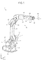
- FIG. 1 is a perspective schematic view illustrating a structure of a robot 1 according to the embodiment.
- FIG. 1 illustrates three-dimensional Cartesian coordinates with the Z-axis along which the vertically upward direction designates a positive direction. Such Cartesian coordinates are used as required in some other drawings in conjunction with the following explanation.
- the robot 1 is a single-arm multi-axis robot, and includes a base 10, a pivoting part 11 pivotably connected to the base 10, and an arm part 20.
- the arm part 20 includes arms, a wrist, a distal movable unit, and the like, the arms being rotatably connected via joints.
- the arm part 20 includes a first joint 21, a first arm 22, a second joint 23, a second arm 24, a wrist 25, and a distal movable unit 26.
- the first joint 21 and the second joint 23 are joints described simply by way of example, and the details about them will be discussed with reference to FIG. 2A and the next drawings.
- the base 10 is fixed to a floor surface or the like.
- the first arm 22 has its proximal end connected to the pivoting part 11 via the first joint 21. This enables the first arm 22 to be supported at its proximal end pivotably around axis S and rotatably around axis L (see arrows A1 and A2 in the drawing).
- the second arm 24 has its proximal end connected to a distal end of the first arm 22 via the second joint 23. This enables the second arm 24 to be supported at its proximal end rotatably around axis U (see an arrow A3 in the drawing). Also, the second arm 24 is provided to be rotatable around axis R (see an arrow A4 in the drawing).
- an end-effector according to the use is attached to the distal movable unit 26.
- the end-effector includes, for example, a robot hand, a welding torch, a laser cutter, or the like.
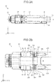
- FIG. 2A is a transparent plan view illustrating the second arm 24.
- FIG. 2B is an enlarged view illustrating a driving device 28 and the surrounding of the same shown in FIG. 2A .
- the second arm 24 is a hollow arm having a hollow part 27 inside.
- the hollow part 27 is an example of a hollow region.
- the hollow part 27 is formed to be communicated with the second joint 23 so as to permit cables to be pulled therein from the second joint 23 or the like.
- the second arm 24 is provided with the driving device 28 that rotates the wrist 25, the distal movable unit 26, and the like.
- the driving device 28 is disposed around the hollow part 27.
- the second arm 24 is a driving body
- the wrist 25 or the distal movable unit 26 is a driven body.
- the driving device 28 includes a first driving unit 281 and a second driving unit 282.
- the first driving unit 281 and the second driving unit 282 include, for example, their respective motors M, brakes Br, and encoders En.
- the brakes and encoders are disposed concentrically with the respective motors M.
- the motors M are not limited to electrical motors, but may be motors such as hydraulic motors.
- the first driving unit 281 has an output shaft 01.
- the second driving unit 282 has an output shaft 02.
- the driving device 28 includes a first hollow shaft 283 and a second hollow shaft 284.
- the first hollow shaft 283 and the second hollow shaft 284 are disposed concentrically with each other.
- the second hollow shaft 284 is disposed outside of the first hollow shaft 283.
- first hollow shaft 283 and the second hollow shaft 284 are arranged concentrically with the center of axis R.
- the axis is not limited to the axis R.
- the 'concentric arrangement' described herein includes any arrangement in which the centers of the shafts slightly deviate from each other, for example, within a range that is acceptable by geometric tolerance.
- FIG. 3A is a schematic sectional view taken along the line A-A of FIG. 2B .
- FIG. 3B is a transparent side view illustrating the second arm 24.
- first hollow shaft 283 and the second hollow shaft 284 are arranged concentrically with the center of the axis R.
- the first driving unit 281 and the second driving unit 282 are disposed along a circumferential direction of the first hollow shaft 283 and the second hollow shaft 284. This can, above all, result in securing the hollow part 27.
- the first hollow shaft 283 has external teeth 283a formed at its outer circumference.
- the output shaft 01 of the first driving unit 281 has a gear 285 that is engaged with the external teeth 283a. With the gear 285 and the external teeth 283a being engaged together, the output shaft 01 of the first driving unit 281 is connected with the first hollow shaft 283.
- the second hollow shaft 284 has internal teeth 284a at its inner circumference.
- the output shaft 02 of the second driving unit 282 also has a gear 286 that is engaged with the internal teeth 284a. With the gear 286 and the internal teeth 284a being engaged together, the output shaft 02 of the second driving unit 282 is connected with the second hollow shaft 284.
- a casing of the second arm 24 can be thinned down tightly (see arrows A7 in the drawing), yet securing the hollow part 27 inside.
- the second arm 24 can be shaped in a slimmer appearance, yet securing the hollow region inside.
- the first hollow shaft 283 further has a tooth surface 287.
- the arm part 20 includes a gear 289 that is engaged with the tooth surface 287.
- the power derived from the first driving unit 281 is consequently output from a final output shaft LO1
- the second hollow shaft 284 further has a tooth surface 288.
- the second arm 24 includes a gear 290 that is engaged with the tooth surface 288.
- the gear 290 being engaged with the tooth surface 288, the power derived from the second driving unit 282 is consequently output from a final output shaft L02.
- each of the first driving unit 281 and the second driving unit 282 includes the single motor M has been described so far.
- the corresponding driving unit may include two or more motors M. Such a modification will now be described, with reference to FIG. 4A to FIG. 5B .
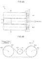
- FIG. 4A is a schematic plan view illustrating a first driving unit 281' according to a modification of the embodiment.
- FIG. 4B is a schematic view illustrating the first driving unit 281' according to the modification when viewed along an arrow C.
- FIG. 4A and FIG. 4B illustrate primarily the first driving unit 281' by way of example, a second driving unit 282' may have the same configuration as the first driving unit 281' in the modification.
- the first driving unit 281' includes a first motor M1, a second motor M2, a brake Br, an encoder En, and a power coupling unit Pc.
- the first motor M1. is provided with an output shaft MO1.
- the second motor M2 is provided with an output shaft MO2
- the brake Br and the encoder En are connected to the output shaft O1 of the first driving unit 281' so that rotation shafts of them are arranged concentrically with the output shaft O1.
- the connected brake Br and encoder En are referred collectively to as 'brake-encoder unit' hereinafter on some occasion.
- the first motor M1, the second motor M2, and the brake-encoder unit provided separately can be located in a side-by-side arrangement, as shown in FIG. 4A by way of example. That is to say, the first driving unit 281' can be reduced in height, or in other words, can be a thinned unit.
- first motor M1, the second motor M2, and the brake-encoder unit are separated from one another, they can be arranged in accordance with the shape of the configuration space or the like without being limited to the side-by-side arrangement. For instance, they may be arranged along the circumferential direction of the first hollow shaft 283 and the second hollow shaft 284. An example of such an arrangement will be described later, referring to FIG. 5A and FIG. 5B .
- the power coupling unit Pc includes a first pulley 281a, a second pulley 281b, a third pulley 281c, and a belt 281d.
- the first pulley 281a is connected to the output shaft MO1 of the first motor M1.
- the second pulley 281b is connected to the output shaft MO2 of the second motor M2.
- the third pulley 281c is connected to the output shaft 01 of the first driving unit 281'.
- the first pulley 281a, the second pulley 281b, and the third pulley 281c are linked together by the belt 281d in such a manner as shown in FIG. 4B by way of example.
- the power derived from the first motor M1 and the second motor M2 can be transmitted to the output shaft 01 of the first driving unit 281' and further output from the output shaft O1.
- the resultant power of 100W can be obtained from the output shaft O1 of the first driving unit 281'. That is to say, the driving unit can be thinned, its components can be arranged in accordance with the shape of the configuration space or the like, and the driving unit can still gain a high output power.
- the third pulley 281c is formed with a reduced pulley ratio, thereby enabling the rotations of the first motor M1 and the second motor M2 to be transmitted to the rotation shaft of the brake-encoder unit with increased speed.
- the encoder En can detect the rotations of the first motor M1. and the second motor M2 at high resolution.
- FIG. 5A is a transparent plan view illustrating the second arm 24 including the driving device 28' according to the modification.
- FIG. 5B is a schematic sectional view taken along the line A'-A' shown in FIG. 5A .
- FIG. 5A corresponds to FIG. 2A and FIG. 5B corresponds to FIG. 3A , explanations for overlapped components are sometimes omitted or otherwise simplified.
- the second arm 24 can mount therein the driving device 28', yet securing the hollow part 27.
- the first driving unit 281' and the second driving unit 282' are arranged along the circumferential direction of the first hollow shaft 283 and the second hollow shaft 284 that are disposed concentrically with the center of axis R.
- the first driving unit 281' is placed at the side opposed to the second driving unit 282' while placing the hollow part 27 therebetween, i.e., is placed at the right side in the drawing.
- the first motor M1. and the second motor M2 are respectively arranged at the lower and upper sides, and the brake-encoder unit (see the reference alphanumeric symbols Br and En) connected to the output shaft O1 is placed at the middle between them.
- first pulley 281a, the second pulley 281b, and the third pulley 281c are linked together by the belt 281d (see FIG. 4B ).
- the second driving unit 282' is placed at the side opposed to the second driving unit 282' while placing the hollow part 27 therebetween, i.e., is placed at the left side in the drawing.
- the first motor M1. and the second motor M2 are respectively arranged at the upper and lower sides, and the brake-encoder unit connected to the output shaft 02 is placed at the middle between them.
- the first pulley 281a, the second pulley 281b, and the third pulley 281c are linked together by the belt 281d (see FIG. 4B ).
- the high-power drive sources, the rotation shafts, and the rotation transmission mechanisms can be accommodated in a compact arrangement around the hollow part 27.
- a frame of the second arm 24 can be thinned down tightly, yet securing the hollow part 27.
- the second arm 24 can be shaped in a slimmer appearance, yet securing the hollow region inside.
- the description in conjunction with FIG. 4A to FIG. 5B provides the exemplary arrangement where the brake-encoder unit is disposed between the first motor M1. and the second motor M2, the embodiment is not limited to this, and alternatively, the brake-encoder unit may be placed in an end.
- the manner in which the belt 281d links the components in the power coupling unit Pc is not limited to the example shown in FIG. 4B , but may be replaced with any alternative if the alternative can correspond to relative arrangement between the first motor M1, the second motor M2, and the brake-encoder unit En.
- the positions of the output shafts 01 and 02 of the first and second driving units 281' and 282' can be freely arranged depending on the relative arrangement between the first motor M1, the second motor M2, and the brake-encoder En and/or the linkage manner of the belt 281d.
- the robot according to the embodiment includes a driving body that includes a driving device that drives a driven body.
- the driving device includes a plurality of hollow shafts and driving units.
- the plurality of hollow shafts are concentrically arranged one another.
- the driving units are disposed along the circumferential direction of the hollow shafts.
- Output shafts of the driving units are connected with the hollow shafts via gears.
- the second arm can be shaped in a slimmer appearance, yet securing its hollow region inside.
- the two driving units namely, the first and second driving units are connected to the two concentric hollow shafts via the gears
- the number of shafts of the final output shaft is not limited to the case.
- three driving units are disposed along the circumferential direction of three concentric hollow shafts and are respectively connected to the three hollow shafts via the gears.
- first and second driving units may be respectively arranged at upper and lower sides in the drawing while placing the hollow region therebetween.
- both the drawings are not intended to limit the number of teeth of the actual gear.
- the drawings are also not intended to limit the shape of the teeth of the gear, and thus the shape of the teeth can be appropriately selected in accordance to desired specifications of spur gears, helical gears, and the like.
- the aforementioned embodiment is described by primarily using the second arm as the example, there is no intention to limit arms that constitute the arm part.
- the aforementioned embodiment may be applied to the first arm.
- the first arm is a driving body
- the second arm is a driven body.
- the aforementioned embodiment may be applied to the pivoting part.
- the pivoting part is a driving body
- the first arm is a driven body.
- the single arm part has two arms, namely, the first arm and the second arm.
- the number of the arms is not limited to two.
- the multi-axis robot where one arm part has six axes. However, it is not intended to limit the number of the axes.
- the multi-axis robot may have seven axes.
- the robot may be a dual-arm robot, or a multi-arm robot that includes three or more arm parts.
Landscapes
- Engineering & Computer Science (AREA)
- Robotics (AREA)
- Mechanical Engineering (AREA)
- Manipulator (AREA)
Abstract
Description
- The embodiment of the disclosure relates to a robot, a robot arm structure, and a driving device. Background
- Conventionally, robots with an arm part that has a plurality of arms rotatably connected via joints have been known in the art. Some of such robots include their arms having a hollow structure so that cables and the like are arranged inside the arm part, for example.
- Rotation shafts, rotation transmission mechanisms, and the like for the arms and a wrist are arranged inside the hollow arms. The joints or the like are loaded with driving devices that have motors serving as drive sources to rotate the arms and the wrist (e.g., see Patent Literature 1).
- The driving device loaded onto the 'industrial robot' disclosed in Patent Literature 1 drives one axis of an arm by using a plurality of motors.
- Patent Literature 1:
Japanese Patent No. 4291344 - However, the conventional art as mentioned above further has room for improvement in having the robot shaped into a slimmer appearance, yet securing hollow regions inside its arms.
- Specifically, under the recent circumstances where multi-axis robots with multiple axes have been widely used, the inside of the above-mentioned hollow arms requires space where the rotation shafts and the rotation transmission mechanisms for multiple axes are arranged, and thus it becomes difficult to secure the hollow region where the cables and the like are arranged.
- The requirements for the drive sources for multiple axes are easy to increase the arrangement space of the driving device. Hence, the arm part and thus the robot, as a whole, are unavoidably increased in dimensions. Such an increase in dimensions of the robot is not desirable because the robot during operation is easy to interfere with other instruments and the like.
- An aspect of the embodiment has been achieved in the light of the aforementioned, and it is an object of the embodiment to provide a robot, a robot arm structure, and a driving device, in which its arm can be shaped in a slimmer appearance, yet securing a hollow region inside therein. Solution to Problem
- A robot according to an aspect of an embodiment includes a driving body including a driving device that drives a driven body. The driving device includes a plurality of hollow shafts and a plurality of driving units. The plurality of hollow shafts are disposed concentrically. The plurality of driving units are disposed along a circumferential direction of the hollow shafts. The output shafts of the driving units are connected to the hollow shafts via gears.
- According to the aspect of the embodiment, the driving body can be shaped in a slimmer appearance, yet securing the hollow region inside therein.
-
-
FIG. 1 is a perspective schematic view illustrating a structure of a robot according to an embodiment. -
FIG. 2A is a transparent plan view illustrating a second arm. -
FIG. 2B is an enlarged view illustrating a driving device and the surrounding of the same shown inFIG. 2A . -
FIG. 3A is a schematic sectional view taken along the line A - A ofFIG. 2B . -
FIG. 3B is a transparent side view illustrating the second arm. -
FIG. 4A is a schematic plan view illustrating a first driving unit according to a modification of the embodiment. -
FIG. 4B is a schematic view illustrating the first driving unit according to the modification when viewed along an arrow C. -
FIG. 5A is a transparent plan view illustrating the second arm including the driving device according to the modification. -
FIG. 5B is a schematic sectional view taken along the line A'-A' ofFIG. 5A . - With reference to the accompanying drawings, an embodiment of a robot, a robot art structure, and a driving device will now be described in detail below. It should not be interpreted that the present embodiment is limited to the embodiment set forth below.
-
FIG. 1 is a perspective schematic view illustrating a structure of a robot 1 according to the embodiment. For the purpose of providing easy-to-understand explanations,FIG. 1 illustrates three-dimensional Cartesian coordinates with the Z-axis along which the vertically upward direction designates a positive direction. Such Cartesian coordinates are used as required in some other drawings in conjunction with the following explanation. - In the following explanation, simply for the convenience of explanation, positional relations of components in the robot 1 will be described on the assumption that the swiveled position of the robot 1 is just as illustrated in
FIG. 1 . - As illustrated in
FIG. 1 , the robot 1 is a single-arm multi-axis robot, and includes abase 10, apivoting part 11 pivotably connected to thebase 10, and anarm part 20. Thearm part 20 includes arms, a wrist, a distal movable unit, and the like, the arms being rotatably connected via joints. - Specifically, the
arm part 20 includes afirst joint 21, afirst arm 22, asecond joint 23, asecond arm 24, awrist 25, and a distalmovable unit 26. Thefirst joint 21 and thesecond joint 23 are joints described simply by way of example, and the details about them will be discussed with reference toFIG. 2A and the next drawings. - The
base 10 is fixed to a floor surface or the like. Thefirst arm 22 has its proximal end connected to thepivoting part 11 via thefirst joint 21. This enables thefirst arm 22 to be supported at its proximal end pivotably around axis S and rotatably around axis L (see arrows A1 and A2 in the drawing). - The
second arm 24 has its proximal end connected to a distal end of thefirst arm 22 via thesecond joint 23. This enables thesecond arm 24 to be supported at its proximal end rotatably around axis U (see an arrow A3 in the drawing). Also, thesecond arm 24 is provided to be rotatable around axis R (see an arrow A4 in the drawing). - Additionally, the
second arm 24, at its distal end, supports a proximal end of thewrist 25 to be rotatable around axis B (see an arrow A5 in the drawing). - Furthermore, the
wrist 25, at its distal end, supports the distalmovable unit 26 so as to be rotatable around axis T (see an arrow A6 in the drawing). Although not shown inFIG. 1 , an end-effector according to the use is attached to the distalmovable unit 26. The end-effector includes, for example, a robot hand, a welding torch, a laser cutter, or the like. - An inner structure of the
arm part 20 will be described. By way of example only, a structure, primarily, of thesecond arm 24 will be described with reference toFIG. 2A and FIG. 2B. FIG. 2A is a transparent plan view illustrating thesecond arm 24.FIG. 2B is an enlarged view illustrating a drivingdevice 28 and the surrounding of the same shown inFIG. 2A . - As shown in
FIG. 2A , thesecond arm 24 is a hollow arm having ahollow part 27 inside. Thehollow part 27 is an example of a hollow region. Thehollow part 27 is formed to be communicated with the second joint 23 so as to permit cables to be pulled therein from the second joint 23 or the like. - The
second arm 24 is provided with the drivingdevice 28 that rotates thewrist 25, the distalmovable unit 26, and the like. The drivingdevice 28 is disposed around thehollow part 27. In this case, thesecond arm 24 is a driving body, and thewrist 25 or the distalmovable unit 26 is a driven body. - The driving
device 28 and the surrounding will be further specifically described. As shown inFIG. 2B , the drivingdevice 28 includes afirst driving unit 281 and asecond driving unit 282. Thefirst driving unit 281 and thesecond driving unit 282 include, for example, their respective motors M, brakes Br, and encoders En. The brakes and encoders are disposed concentrically with the respective motors M. The motors M are not limited to electrical motors, but may be motors such as hydraulic motors. - The
first driving unit 281 has anoutput shaft 01. Thesecond driving unit 282 has anoutput shaft 02. - The driving
device 28 includes a firsthollow shaft 283 and a secondhollow shaft 284. The firsthollow shaft 283 and the secondhollow shaft 284 are disposed concentrically with each other. In the embodiment, the secondhollow shaft 284 is disposed outside of the firsthollow shaft 283. - Herein, the first
hollow shaft 283 and the secondhollow shaft 284 are arranged concentrically with the center of axis R. However, the axis is not limited to the axis R. The 'concentric arrangement' described herein includes any arrangement in which the centers of the shafts slightly deviate from each other, for example, within a range that is acceptable by geometric tolerance. - A structure of connections that connect the first and second
hollow shafts second driving units FIG. 3A and FIG. 3B . -
FIG. 3A is a schematic sectional view taken along the line A-A ofFIG. 2B .FIG. 3B is a transparent side view illustrating thesecond arm 24. - As has been described above, and, as can be seen in
FIG. 3A , the firsthollow shaft 283 and the secondhollow shaft 284 are arranged concentrically with the center of the axis R. Thefirst driving unit 281 and thesecond driving unit 282 are disposed along a circumferential direction of the firsthollow shaft 283 and the secondhollow shaft 284. This can, above all, result in securing thehollow part 27. - Also, as shown in
FIG. 3A , the firsthollow shaft 283 hasexternal teeth 283a formed at its outer circumference. Theoutput shaft 01 of thefirst driving unit 281 has agear 285 that is engaged with theexternal teeth 283a. With thegear 285 and theexternal teeth 283a being engaged together, theoutput shaft 01 of thefirst driving unit 281 is connected with the firsthollow shaft 283. - Meanwhile, the second
hollow shaft 284 hasinternal teeth 284a at its inner circumference. Theoutput shaft 02 of thesecond driving unit 282 also has agear 286 that is engaged with theinternal teeth 284a. With thegear 286 and theinternal teeth 284a being engaged together, theoutput shaft 02 of thesecond driving unit 282 is connected with the secondhollow shaft 284. - The above-mentioned connections structured in this manner can bring about a compact accommodation of the drive sources, the rotation shafts, and the rotation transmission mechanisms for the multiple axes, at the periphery of the
hollow part 27. Thus, as can be seen inFIG. 3B by way of example, a casing of thesecond arm 24 can be thinned down tightly (see arrows A7 in the drawing), yet securing thehollow part 27 inside. In other words, thesecond arm 24 can be shaped in a slimmer appearance, yet securing the hollow region inside. - Referring back to
FIG. 2B , the discussion will be continued. As shown inFIG. 2B , the firsthollow shaft 283 further has atooth surface 287. Thearm part 20 includes agear 289 that is engaged with thetooth surface 287.
Thus, with thegear 289 being engaged with thetooth surface 287, the power derived from thefirst driving unit 281 is consequently output from a final output shaft LO1 - Meanwhile, the second
hollow shaft 284 further has atooth surface 288. Thesecond arm 24 includes agear 290 that is engaged with thetooth surface 288. Thus, with thegear 290 being engaged with thetooth surface 288, the power derived from thesecond driving unit 282 is consequently output from a final output shaft L02. - The example where each of the
first driving unit 281 and thesecond driving unit 282 includes the single motor M has been described so far. However, in case the output power of thefirst driving unit 281 or thesecond driving unit 282 should be increased, the corresponding driving unit may include two or more motors M. Such a modification will now be described, with reference toFIG. 4A to FIG. 5B . -
FIG. 4A is a schematic plan view illustrating a first driving unit 281' according to a modification of the embodiment.FIG. 4B is a schematic view illustrating the first driving unit 281' according to the modification when viewed along an arrow C. AlthoughFIG. 4A and FIG. 4B illustrate primarily the first driving unit 281' by way of example, a second driving unit 282' may have the same configuration as the first driving unit 281' in the modification. - As shown in
FIG. 4A , the first driving unit 281' according to the modification includes a first motor M1, a second motor M2, a brake Br, an encoder En, and a power coupling unit Pc. - The first motor M1. is provided with an output shaft MO1. The second motor M2 is provided with an output shaft MO2 The brake Br and the encoder En are connected to the output shaft O1 of the first driving unit 281' so that rotation shafts of them are arranged concentrically with the output shaft O1. The connected brake Br and encoder En are referred collectively to as 'brake-encoder unit' hereinafter on some occasion.
- The first motor M1, the second motor M2, and the brake-encoder unit provided separately can be located in a side-by-side arrangement, as shown in
FIG. 4A by way of example. That is to say, the first driving unit 281' can be reduced in height, or in other words, can be a thinned unit. - Furthermore, because the first motor M1, the second motor M2, and the brake-encoder unit are separated from one another, they can be arranged in accordance with the shape of the configuration space or the like without being limited to the side-by-side arrangement. For instance, they may be arranged along the circumferential direction of the first
hollow shaft 283 and the secondhollow shaft 284. An example of such an arrangement will be described later, referring toFIG. 5A and FIG. 5B . - As illustrated in
FIG. 4B , the power coupling unit Pc includes afirst pulley 281a, asecond pulley 281b, athird pulley 281c, and abelt 281d. - The
first pulley 281a is connected to the output shaft MO1 of the first motor M1. Thesecond pulley 281b is connected to the output shaft MO2 of the second motor M2. Thethird pulley 281c is connected to theoutput shaft 01 of the first driving unit 281'. - The
first pulley 281a, thesecond pulley 281b, and thethird pulley 281c are linked together by thebelt 281d in such a manner as shown inFIG. 4B by way of example. In this manner, the power derived from the first motor M1 and the second motor M2 can be transmitted to theoutput shaft 01 of the first driving unit 281' and further output from the output shaft O1. - In the event that each of the first motor M1. and the second motor M2 has the identical rated power of 50W (Watts), the resultant power of 100W can be obtained from the output shaft O1 of the first driving unit 281'. That is to say, the driving unit can be thinned, its components can be arranged in accordance with the shape of the configuration space or the like, and the driving unit can still gain a high output power.
- Also, as shown in
FIG. 4B , in comparison with thefirst pulley 281a and thesecond pulley 281b, thethird pulley 281c is formed with a reduced pulley ratio, thereby enabling the rotations of the first motor M1 and the second motor M2 to be transmitted to the rotation shaft of the brake-encoder unit with increased speed. - Thus, a brake capacity of the brake Br can be reduced, or the brake Br can have compact structure. The encoder En can detect the rotations of the first motor M1. and the second motor M2 at high resolution.
- Hereinafter, the driving device loaded with the first driving unit 281' (and the second driving unit 282') described in conjunction with
FIG. 4A and FIG. 4B will be denoted by the reference numeric symbol "28'". - Then, an exemplary case where the driving device is loaded with the first driving unit 281' and the second driving unit 282' will be set forth.
FIG. 5A is a transparent plan view illustrating thesecond arm 24 including the driving device 28' according to the modification.FIG. 5B is a schematic sectional view taken along the line A'-A' shown inFIG. 5A . - Because
FIG. 5A corresponds toFIG. 2A andFIG. 5B corresponds toFIG. 3A , explanations for overlapped components are sometimes omitted or otherwise simplified. - As shown in
FIG. 5A , thesecond arm 24 can mount therein the driving device 28', yet securing thehollow part 27. - Specifically, as shown in
FIG. 5B , the first driving unit 281' and the second driving unit 282' are arranged along the circumferential direction of the firsthollow shaft 283 and the secondhollow shaft 284 that are disposed concentrically with the center of axis R. - For instance, the first driving unit 281' is placed at the side opposed to the second driving unit 282' while placing the
hollow part 27 therebetween, i.e., is placed at the right side in the drawing. Moreover, the first motor M1. and the second motor M2 are respectively arranged at the lower and upper sides, and the brake-encoder unit (see the reference alphanumeric symbols Br and En) connected to the output shaft O1 is placed at the middle between them. - Although not shown in that drawing, the
first pulley 281a, thesecond pulley 281b, and thethird pulley 281c are linked together by thebelt 281d (seeFIG. 4B ). - On the other hand, as shown in
FIG. 5B , the second driving unit 282' is placed at the side opposed to the second driving unit 282' while placing thehollow part 27 therebetween, i.e., is placed at the left side in the drawing. Moreover, the first motor M1. and the second motor M2 are respectively arranged at the upper and lower sides, and the brake-encoder unit connected to theoutput shaft 02 is placed at the middle between them. - Although not shown in the drawing, similar to the first driving unit 281', in the second driving unit 282', the
first pulley 281a, thesecond pulley 281b, and thethird pulley 281c are linked together by thebelt 281d (seeFIG. 4B ). - In this manner, the high-power drive sources, the rotation shafts, and the rotation transmission mechanisms can be accommodated in a compact arrangement around the
hollow part 27. Thus, as shown inFIG. 3B , for instance, a frame of thesecond arm 24 can be thinned down tightly, yet securing thehollow part 27. In other word, thesecond arm 24 can be shaped in a slimmer appearance, yet securing the hollow region inside. - Although the description in conjunction with
FIG. 4A to FIG. 5B provides the exemplary arrangement where the brake-encoder unit is disposed between the first motor M1. and the second motor M2, the embodiment is not limited to this, and alternatively, the brake-encoder unit may be placed in an end. - Also, the manner in which the
belt 281d links the components in the power coupling unit Pc is not limited to the example shown inFIG. 4B , but may be replaced with any alternative if the alternative can correspond to relative arrangement between the first motor M1, the second motor M2, and the brake-encoder unit En. - In other words, the positions of the
output shafts belt 281d. - As has been described, the robot according to the embodiment includes a driving body that includes a driving device that drives a driven body. The driving device includes a plurality of hollow shafts and driving units. The plurality of hollow shafts are concentrically arranged one another. The driving units are disposed along the circumferential direction of the hollow shafts. Output shafts of the driving units are connected with the hollow shafts via gears.
- Thus, in the robot according to the embodiment, the second arm can be shaped in a slimmer appearance, yet securing its hollow region inside.
- In the aforementioned embodiment, there has been described the exemplary case where the two driving units, namely, the first and second driving units are connected to the two concentric hollow shafts via the gears, in other words, the case where the final output shaft corresponding to two shafts is obtained. However, the number of shafts of the final output shaft is not limited to the case.
- For example, if desired to have the final output shaft corresponding to three shafts, it is sufficient that three driving units are disposed along the circumferential direction of three concentric hollow shafts and are respectively connected to the three hollow shafts via the gears.
- Also, in the aforementioned embodiment, there has been described the exemplary case where the first and second driving units are respectively arranged at right and left sides in the drawing while placing the hollow region therebetween (see
FIG. 3A orFIG. 5B ). However, it is not intended to limit the arrangement of the driving units. - For example, the first and second driving units may be respectively arranged at upper and lower sides in the drawing while placing the hollow region therebetween.
- Further, although, in the aforementioned embodiment, the exemplary engagement of the gears in the driving device is depicted in
FIG. 3A orFIG. 5B , both the drawings are not intended to limit the number of teeth of the actual gear. The drawings are also not intended to limit the shape of the teeth of the gear, and thus the shape of the teeth can be appropriately selected in accordance to desired specifications of spur gears, helical gears, and the like. - Moreover, in the aforementioned embodiment, there has been described the example where the brake and the encoder are disposed in a concentric arrangement. However, they may not necessarily be concentric.
- Furthermore, although the aforementioned embodiment is described by primarily using the second arm as the example, there is no intention to limit arms that constitute the arm part. Thus, the aforementioned embodiment may be applied to the first arm. In such a case, the first arm is a driving body, and the second arm is a driven body. The aforementioned embodiment may be applied to the pivoting part. In such a case, the pivoting part is a driving body, and the first arm is a driven body.
- Also, in the aforementioned embodiment, there has been described an exemplary case where the single arm part has two arms, namely, the first arm and the second arm. However, the number of the arms is not limited to two.
- Moreover, in the aforementioned embodiment, there has been described the example of the multi-axis robot where one arm part has six axes. However, it is not intended to limit the number of the axes. For example, the multi-axis robot may have seven axes.
- Also, although the aforementioned embodiment is described by using the single arm robot as the example, it is not intended to be limited to this. The robot may be a dual-arm robot, or a multi-arm robot that includes three or more arm parts.
- Additional advantages and modifications will readily occur to those skilled in the art. Therefore, the invention in its broader aspects is not limited to the specific details and representative embodiments shown and described herein. Accordingly, various modifications may be made without departing from the spirit or scrape of the general inventive concept as defined by the appended claims and their equivalents.
-
- 1
- Robot
- 10
- Base
- 11
- Pivoting Part
- 20
- Arm Part
- 21
- First Joint
- 22
- First Arm
- 23
- Second Joint
- 24
- Second Arm
- 25
- Wrist
- 26
- Distal Movable Unit
- 27
- Hollow Part
- 28
- Driving Device
- 281
- First Driving Unit
- 281a
- First Pulley
- 281b
- Second Pulley
- 281c
- Third Pulley
- 281d
- Belt
- 282
- Second Driving Unit
- 283
- First Hollow Shaft
- 283a
- External teeth
- 284
- Second Hollow Shaft
- 284a
- Internal teeth
- 285
- Gear
- 286
- Gear
- 287
- Tooth Surface
- 288
- Tooth Surface
- 289
- Gear
- 290
- Gear
- A to A7
- Arrows
- B
- Axis
- Br
- Brake
- En
- Encoder
- L
- Axis
- LO1, LO2
- Final Output Shaft
- M
- Motor
- M1
- First Motor
- M2
- Second Motor
- MO1, MO2
- Output Shaft
- 01, 02
- Output Shaft
- Pc
- Power Coupling Unit
- R
- Axis
- S
- Axis
- T
- Axis
- U
- Axis
Claims (7)
- A robot comprising
a driving body including a driving device that drives a driven body,
the driving device comprising:a plurality of hollow shafts disposed concentrically; anda plurality of driving units disposed along a circumferential direction of the plurality of the hollow shafts, whereinoutput shafts of the driving units are connected to the hollow shafts via gears. - The robot according to claim 1, wherein the driving device comprises:a first hollow shaft having external teeth at its outer circumference;a second hollow shaft disposed outside of the first hollow shaft and having internal teeth at its inner circumference;a first driving unit of which the output shaft has a gear engaged with the external teeth; anda second driving unit of which the output shaft has a gear engaged with the internal teeth.
- The robot according to claim 1 or claim 2, wherein
the driving unit includes:a plurality of motors; anda power coupling unit coupling powers from the plurality of motors to enable the output shaft to output the coupled powers, andthe plurality of motors are arranged along the circumferential direction of the hollow shafts. - The robot according to claim 3, wherein the power coupling unit is composed of a combination of pulleys and a belt.
- A robot arm structure including a driving device, the driving device comprising:a plurality of hollow shafts disposed concentrically; anda plurality of driving units disposed along a circumferential direction of the hollow shafts, whereinoutput shafts of the driving units are connected to the hollow shafts via gears.
- A driving device comprising:a plurality of hollow shafts disposed concentrically; anda plurality of driving units disposed along a circumferential direction of the hollow shafts, whereinoutput shafts of the driving units are connected to the hollow shafts via gears.
- The driving device according to claim 6, wherein
the driving unit includes:a plurality of motors; anda power coupling unit coupling powers from the plurality of motors to enable the output shaft to output the coupled powers, andthe plurality of motors are arranged along the circumferential direction of the hollow shafts.
Applications Claiming Priority (1)
| Application Number | Priority Date | Filing Date | Title |
|---|---|---|---|
| PCT/JP2013/068373 WO2015001643A1 (en) | 2013-07-04 | 2013-07-04 | Robot, arm structure for robot, and actuating device |
Publications (3)
| Publication Number | Publication Date |
|---|---|
| EP3017921A1 true EP3017921A1 (en) | 2016-05-11 |
| EP3017921A4 EP3017921A4 (en) | 2017-07-05 |
| EP3017921B1 EP3017921B1 (en) | 2019-10-16 |
Family
ID=52143262
Family Applications (1)
| Application Number | Title | Priority Date | Filing Date |
|---|---|---|---|
| EP13888568.6A Active EP3017921B1 (en) | 2013-07-04 | 2013-07-04 | Robot, arm structure for robot, and actuating device |
Country Status (5)
| Country | Link |
|---|---|
| US (1) | US20160101518A1 (en) |
| EP (1) | EP3017921B1 (en) |
| JP (1) | JP6256470B2 (en) |
| CN (1) | CN105246657B (en) |
| WO (1) | WO2015001643A1 (en) |
Cited By (1)
| Publication number | Priority date | Publication date | Assignee | Title |
|---|---|---|---|---|
| CN106034770A (en) * | 2016-06-24 | 2016-10-26 | 天津迈克重工有限公司 | 360-degree rotating device for multifunctional trimming robot |
Families Citing this family (16)
| Publication number | Priority date | Publication date | Assignee | Title |
|---|---|---|---|---|
| KR101643392B1 (en) * | 2015-05-19 | 2016-07-27 | 주식회사 민트로봇 | Hollow Type Actuator Having Parallel Structure |
| GB2541369B (en) * | 2015-07-22 | 2021-03-31 | Cmr Surgical Ltd | Drive mechanisms for robot arms |
| GB2540756B (en) * | 2015-07-22 | 2021-03-31 | Cmr Surgical Ltd | Gear packaging for robot arms |
| US10926404B2 (en) | 2015-07-22 | 2021-02-23 | Cmr Surgical Limited | Gear packaging for robot arms |
| KR101714505B1 (en) * | 2015-11-13 | 2017-03-09 | 서강대학교산학협력단 | Actuating Device And Multi-Joint Walking Robot Having The Same |
| JP6174107B2 (en) * | 2015-12-21 | 2017-08-02 | 上銀科技股▲分▼有限公司 | Drive transmission device |
| KR101764157B1 (en) * | 2016-06-30 | 2017-08-02 | 주식회사 민트로봇 | Hollow Type Actuator Having Parallel Structure |
| IT201600130715A1 (en) * | 2016-12-23 | 2018-06-23 | Comau Spa | "Functional device, in particular robots, with modular modules for educational use" |
| US10022861B1 (en) | 2017-04-27 | 2018-07-17 | Engineering Services Inc. | Two joint module and arm using same |
| USD802041S1 (en) * | 2017-04-27 | 2017-11-07 | Engineering Services Inc | Robotic arm |
| USD929481S1 (en) * | 2018-04-27 | 2021-08-31 | Staubli Faverges | Industrial robots |
| US10857677B2 (en) * | 2018-10-04 | 2020-12-08 | Caterpillar Inc. | Tip attachment to aid in programming a collaborative robot |
| JP7101134B2 (en) | 2019-03-11 | 2022-07-14 | ファナック株式会社 | robot |
| US20250114948A1 (en) * | 2023-10-05 | 2025-04-10 | Lockheed Martin Corporation | Marking end effectors for robotic systems |
| USD1109205S1 (en) * | 2023-12-28 | 2026-01-13 | Kuka Robotics Guangdong Co., Ltd. | Industrial robot |
| USD1112405S1 (en) * | 2023-12-28 | 2026-02-10 | Kuka Robotics Guangdong Co., Ltd. | Industrial robot |
Family Cites Families (15)
| Publication number | Priority date | Publication date | Assignee | Title |
|---|---|---|---|---|
| JPS61152381A (en) * | 1984-12-27 | 1986-07-11 | 株式会社デンソー | Industrial robot |
| JPS62140794A (en) * | 1985-12-17 | 1987-06-24 | フアナツク株式会社 | Cable treater for industrial robot |
| JP2772863B2 (en) * | 1990-08-21 | 1998-07-09 | 住友重機械工業株式会社 | Stirrer with concentric 2-output shaft reducer |
| US5293107A (en) * | 1993-02-24 | 1994-03-08 | Fanuc Robotics North America, Inc. | Motorized rotary joint and method of constructing a modular robot utilizing same |
| IT1292275B1 (en) * | 1997-04-23 | 1999-01-29 | Comau Spa | INDUSTRIAL ROBOT WRIST, AND ROBOT INCLUDING SUCH WRIST. |
| JP2001277176A (en) * | 2000-03-30 | 2001-10-09 | Shibaura Mechatronics Corp | Turning device |
| ITPI20040077A1 (en) * | 2004-10-14 | 2005-01-14 | Univ Pisa | GEAR MOTOR MECHANISM WITH VARIABLE AND QUICKLY CONTROLLABLE RIGIDITY |
| JP4291344B2 (en) * | 2006-08-31 | 2009-07-08 | ファナック株式会社 | Industrial robot |
| CN102079089A (en) * | 2009-11-30 | 2011-06-01 | 鸿富锦精密工业(深圳)有限公司 | Robot |
| KR101687627B1 (en) * | 2010-01-12 | 2016-12-21 | 삼성전자주식회사 | Robot joint driving apparatus and robot having the same |
| JP2012147541A (en) * | 2011-01-11 | 2012-08-02 | Seiko Epson Corp | Electromechanical device, and actuator, motor, robot, and robot hand using the same |
| WO2012104785A1 (en) * | 2011-01-31 | 2012-08-09 | Csir | Drive apparatus |
| CN103084293A (en) * | 2011-10-31 | 2013-05-08 | 鸿富锦精密工业(深圳)有限公司 | Robot arm part |
| CH706455A2 (en) * | 2012-04-30 | 2013-10-31 | Trimos S A | articulated mechanical arm equipped with a passive device of the gravity compensation. |
| TWI480139B (en) * | 2012-10-15 | 2015-04-11 | Delta Electronics Inc | Robot joint and robot arm using the same |
-
2013
- 2013-07-04 JP JP2015524972A patent/JP6256470B2/en active Active
- 2013-07-04 CN CN201380076884.2A patent/CN105246657B/en active Active
- 2013-07-04 EP EP13888568.6A patent/EP3017921B1/en active Active
- 2013-07-04 WO PCT/JP2013/068373 patent/WO2015001643A1/en not_active Ceased
-
2015
- 2015-12-16 US US14/970,540 patent/US20160101518A1/en not_active Abandoned
Non-Patent Citations (1)
| Title |
|---|
| See references of WO2015001643A1 * |
Cited By (1)
| Publication number | Priority date | Publication date | Assignee | Title |
|---|---|---|---|---|
| CN106034770A (en) * | 2016-06-24 | 2016-10-26 | 天津迈克重工有限公司 | 360-degree rotating device for multifunctional trimming robot |
Also Published As
| Publication number | Publication date |
|---|---|
| CN105246657B (en) | 2018-10-09 |
| EP3017921A4 (en) | 2017-07-05 |
| EP3017921B1 (en) | 2019-10-16 |
| JPWO2015001643A1 (en) | 2017-02-23 |
| CN105246657A (en) | 2016-01-13 |
| US20160101518A1 (en) | 2016-04-14 |
| JP6256470B2 (en) | 2018-01-10 |
| WO2015001643A1 (en) | 2015-01-08 |
Similar Documents
| Publication | Publication Date | Title |
|---|---|---|
| EP3017921B1 (en) | Robot, arm structure for robot, and actuating device | |
| JP5462064B2 (en) | Industrial robot | |
| JP6963152B2 (en) | Robot wrist structure and robot | |
| US11597102B2 (en) | Gear packaging for robotic joints | |
| US9095982B2 (en) | Drive apparatus and robot | |
| US9752665B2 (en) | Compliance motor structure and manufacturing method thereof | |
| JP6088362B2 (en) | Industrial robot wrist drive structure with 3 degrees of freedom of rotation | |
| JPH04226882A (en) | Industrial robots and their manufacturing methods | |
| JPH04256593A (en) | Industrial robot arm structure | |
| CN102594010A (en) | Electric machine device, actuator using the same, motor, robot, and robot hand | |
| US20110154932A1 (en) | Robot arm assembly and robot using the same | |
| CN113520602A (en) | A mechanical arm structure, pre-positioning structure and surgical robot | |
| JP2018075675A (en) | Operation device and double arm type operation device | |
| US20130125690A1 (en) | Robot arm assembly | |
| JP2015085446A (en) | robot | |
| JP5158710B2 (en) | Interference drive joint mechanism | |
| US20250162137A1 (en) | Robot and method for manufacturing robot | |
| CN108524002A (en) | A kind of mechanically decoupled single hole surgical robot quick replacement mechanism with linear joint | |
| CN112549071B (en) | Robotic arms and robots | |
| WO2015001602A1 (en) | Robot, arm structure for robot, and actuating device | |
| JP2010214527A (en) | Arm structure of industrial robot | |
| CN209793719U (en) | Manipulator connecting support assembly | |
| WO2021087457A1 (en) | Harmonic drive actuator gearhead | |
| CN209793720U (en) | Manipulator connecting support assembly | |
| CN210173609U (en) | Robot wrist |
Legal Events
| Date | Code | Title | Description |
|---|---|---|---|
| PUAI | Public reference made under article 153(3) epc to a published international application that has entered the european phase |
Free format text: ORIGINAL CODE: 0009012 |
|
| 17P | Request for examination filed |
Effective date: 20151216 |
|
| AK | Designated contracting states |
Kind code of ref document: A1 Designated state(s): AL AT BE BG CH CY CZ DE DK EE ES FI FR GB GR HR HU IE IS IT LI LT LU LV MC MK MT NL NO PL PT RO RS SE SI SK SM TR |
|
| AX | Request for extension of the european patent |
Extension state: BA ME |
|
| DAX | Request for extension of the european patent (deleted) | ||
| A4 | Supplementary search report drawn up and despatched |
Effective date: 20170602 |
|
| RIC1 | Information provided on ipc code assigned before grant |
Ipc: B25J 9/12 20060101ALI20170529BHEP Ipc: B25J 18/00 20060101ALI20170529BHEP Ipc: B25J 9/10 20060101ALI20170529BHEP Ipc: B25J 17/00 20060101AFI20170529BHEP |
|
| STAA | Information on the status of an ep patent application or granted ep patent |
Free format text: STATUS: EXAMINATION IS IN PROGRESS |
|
| 17Q | First examination report despatched |
Effective date: 20180907 |
|
| RIC1 | Information provided on ipc code assigned before grant |
Ipc: B25J 9/00 20060101ALI20190502BHEP Ipc: B25J 9/12 20060101ALI20190502BHEP Ipc: B25J 17/00 20060101AFI20190502BHEP Ipc: B25J 18/00 20060101ALI20190502BHEP Ipc: B25J 9/10 20060101ALI20190502BHEP |
|
| GRAJ | Information related to disapproval of communication of intention to grant by the applicant or resumption of examination proceedings by the epo deleted |
Free format text: ORIGINAL CODE: EPIDOSDIGR1 |
|
| STAA | Information on the status of an ep patent application or granted ep patent |
Free format text: STATUS: GRANT OF PATENT IS INTENDED |
|
| GRAP | Despatch of communication of intention to grant a patent |
Free format text: ORIGINAL CODE: EPIDOSNIGR1 |
|
| INTG | Intention to grant announced |
Effective date: 20190621 |
|
| RIN1 | Information on inventor provided before grant (corrected) |
Inventor name: ICHIBANGASE, ATSUSHI Inventor name: SAITO, HIROSHI Inventor name: TANAKA, KENTARO |
|
| GRAS | Grant fee paid |
Free format text: ORIGINAL CODE: EPIDOSNIGR3 |
|
| GRAA | (expected) grant |
Free format text: ORIGINAL CODE: 0009210 |
|
| STAA | Information on the status of an ep patent application or granted ep patent |
Free format text: STATUS: THE PATENT HAS BEEN GRANTED |
|
| AK | Designated contracting states |
Kind code of ref document: B1 Designated state(s): AL AT BE BG CH CY CZ DE DK EE ES FI FR GB GR HR HU IE IS IT LI LT LU LV MC MK MT NL NO PL PT RO RS SE SI SK SM TR |
|
| REG | Reference to a national code |
Ref country code: GB Ref legal event code: FG4D |
|
| REG | Reference to a national code |
Ref country code: DE Ref legal event code: R096 Ref document number: 602013061880 Country of ref document: DE Ref country code: CH Ref legal event code: EP |
|
| REG | Reference to a national code |
Ref country code: IE Ref legal event code: FG4D |
|
| REG | Reference to a national code |
Ref country code: AT Ref legal event code: REF Ref document number: 1190842 Country of ref document: AT Kind code of ref document: T Effective date: 20191115 |
|
| REG | Reference to a national code |
Ref country code: NL Ref legal event code: MP Effective date: 20191016 |
|
| REG | Reference to a national code |
Ref country code: LT Ref legal event code: MG4D |
|
| REG | Reference to a national code |
Ref country code: AT Ref legal event code: MK05 Ref document number: 1190842 Country of ref document: AT Kind code of ref document: T Effective date: 20191016 |
|
| PG25 | Lapsed in a contracting state [announced via postgrant information from national office to epo] |
Ref country code: BG Free format text: LAPSE BECAUSE OF FAILURE TO SUBMIT A TRANSLATION OF THE DESCRIPTION OR TO PAY THE FEE WITHIN THE PRESCRIBED TIME-LIMIT Effective date: 20200116 Ref country code: FI Free format text: LAPSE BECAUSE OF FAILURE TO SUBMIT A TRANSLATION OF THE DESCRIPTION OR TO PAY THE FEE WITHIN THE PRESCRIBED TIME-LIMIT Effective date: 20191016 Ref country code: GR Free format text: LAPSE BECAUSE OF FAILURE TO SUBMIT A TRANSLATION OF THE DESCRIPTION OR TO PAY THE FEE WITHIN THE PRESCRIBED TIME-LIMIT Effective date: 20200117 Ref country code: PT Free format text: LAPSE BECAUSE OF FAILURE TO SUBMIT A TRANSLATION OF THE DESCRIPTION OR TO PAY THE FEE WITHIN THE PRESCRIBED TIME-LIMIT Effective date: 20200217 Ref country code: LT Free format text: LAPSE BECAUSE OF FAILURE TO SUBMIT A TRANSLATION OF THE DESCRIPTION OR TO PAY THE FEE WITHIN THE PRESCRIBED TIME-LIMIT Effective date: 20191016 Ref country code: AT Free format text: LAPSE BECAUSE OF FAILURE TO SUBMIT A TRANSLATION OF THE DESCRIPTION OR TO PAY THE FEE WITHIN THE PRESCRIBED TIME-LIMIT Effective date: 20191016 Ref country code: NL Free format text: LAPSE BECAUSE OF FAILURE TO SUBMIT A TRANSLATION OF THE DESCRIPTION OR TO PAY THE FEE WITHIN THE PRESCRIBED TIME-LIMIT Effective date: 20191016 Ref country code: PL Free format text: LAPSE BECAUSE OF FAILURE TO SUBMIT A TRANSLATION OF THE DESCRIPTION OR TO PAY THE FEE WITHIN THE PRESCRIBED TIME-LIMIT Effective date: 20191016 Ref country code: LV Free format text: LAPSE BECAUSE OF FAILURE TO SUBMIT A TRANSLATION OF THE DESCRIPTION OR TO PAY THE FEE WITHIN THE PRESCRIBED TIME-LIMIT Effective date: 20191016 Ref country code: SE Free format text: LAPSE BECAUSE OF FAILURE TO SUBMIT A TRANSLATION OF THE DESCRIPTION OR TO PAY THE FEE WITHIN THE PRESCRIBED TIME-LIMIT Effective date: 20191016 Ref country code: NO Free format text: LAPSE BECAUSE OF FAILURE TO SUBMIT A TRANSLATION OF THE DESCRIPTION OR TO PAY THE FEE WITHIN THE PRESCRIBED TIME-LIMIT Effective date: 20200116 |
|
| PG25 | Lapsed in a contracting state [announced via postgrant information from national office to epo] |
Ref country code: IS Free format text: LAPSE BECAUSE OF FAILURE TO SUBMIT A TRANSLATION OF THE DESCRIPTION OR TO PAY THE FEE WITHIN THE PRESCRIBED TIME-LIMIT Effective date: 20200224 Ref country code: RS Free format text: LAPSE BECAUSE OF FAILURE TO SUBMIT A TRANSLATION OF THE DESCRIPTION OR TO PAY THE FEE WITHIN THE PRESCRIBED TIME-LIMIT Effective date: 20191016 Ref country code: HR Free format text: LAPSE BECAUSE OF FAILURE TO SUBMIT A TRANSLATION OF THE DESCRIPTION OR TO PAY THE FEE WITHIN THE PRESCRIBED TIME-LIMIT Effective date: 20191016 |
|
| PG25 | Lapsed in a contracting state [announced via postgrant information from national office to epo] |
Ref country code: AL Free format text: LAPSE BECAUSE OF FAILURE TO SUBMIT A TRANSLATION OF THE DESCRIPTION OR TO PAY THE FEE WITHIN THE PRESCRIBED TIME-LIMIT Effective date: 20191016 |
|
| REG | Reference to a national code |
Ref country code: DE Ref legal event code: R097 Ref document number: 602013061880 Country of ref document: DE |
|
| PG2D | Information on lapse in contracting state deleted |
Ref country code: IS |
|
| PG25 | Lapsed in a contracting state [announced via postgrant information from national office to epo] |
Ref country code: ES Free format text: LAPSE BECAUSE OF FAILURE TO SUBMIT A TRANSLATION OF THE DESCRIPTION OR TO PAY THE FEE WITHIN THE PRESCRIBED TIME-LIMIT Effective date: 20191016 Ref country code: RO Free format text: LAPSE BECAUSE OF FAILURE TO SUBMIT A TRANSLATION OF THE DESCRIPTION OR TO PAY THE FEE WITHIN THE PRESCRIBED TIME-LIMIT Effective date: 20191016 Ref country code: CZ Free format text: LAPSE BECAUSE OF FAILURE TO SUBMIT A TRANSLATION OF THE DESCRIPTION OR TO PAY THE FEE WITHIN THE PRESCRIBED TIME-LIMIT Effective date: 20191016 Ref country code: EE Free format text: LAPSE BECAUSE OF FAILURE TO SUBMIT A TRANSLATION OF THE DESCRIPTION OR TO PAY THE FEE WITHIN THE PRESCRIBED TIME-LIMIT Effective date: 20191016 Ref country code: DK Free format text: LAPSE BECAUSE OF FAILURE TO SUBMIT A TRANSLATION OF THE DESCRIPTION OR TO PAY THE FEE WITHIN THE PRESCRIBED TIME-LIMIT Effective date: 20191016 Ref country code: IS Free format text: LAPSE BECAUSE OF FAILURE TO SUBMIT A TRANSLATION OF THE DESCRIPTION OR TO PAY THE FEE WITHIN THE PRESCRIBED TIME-LIMIT Effective date: 20200216 |
|
| PLBE | No opposition filed within time limit |
Free format text: ORIGINAL CODE: 0009261 |
|
| STAA | Information on the status of an ep patent application or granted ep patent |
Free format text: STATUS: NO OPPOSITION FILED WITHIN TIME LIMIT |
|
| PG25 | Lapsed in a contracting state [announced via postgrant information from national office to epo] |
Ref country code: SK Free format text: LAPSE BECAUSE OF FAILURE TO SUBMIT A TRANSLATION OF THE DESCRIPTION OR TO PAY THE FEE WITHIN THE PRESCRIBED TIME-LIMIT Effective date: 20191016 Ref country code: IT Free format text: LAPSE BECAUSE OF FAILURE TO SUBMIT A TRANSLATION OF THE DESCRIPTION OR TO PAY THE FEE WITHIN THE PRESCRIBED TIME-LIMIT Effective date: 20191016 Ref country code: SM Free format text: LAPSE BECAUSE OF FAILURE TO SUBMIT A TRANSLATION OF THE DESCRIPTION OR TO PAY THE FEE WITHIN THE PRESCRIBED TIME-LIMIT Effective date: 20191016 |
|
| 26N | No opposition filed |
Effective date: 20200717 |
|
| PG25 | Lapsed in a contracting state [announced via postgrant information from national office to epo] |
Ref country code: SI Free format text: LAPSE BECAUSE OF FAILURE TO SUBMIT A TRANSLATION OF THE DESCRIPTION OR TO PAY THE FEE WITHIN THE PRESCRIBED TIME-LIMIT Effective date: 20191016 |
|
| PG25 | Lapsed in a contracting state [announced via postgrant information from national office to epo] |
Ref country code: MC Free format text: LAPSE BECAUSE OF FAILURE TO SUBMIT A TRANSLATION OF THE DESCRIPTION OR TO PAY THE FEE WITHIN THE PRESCRIBED TIME-LIMIT Effective date: 20191016 |
|
| REG | Reference to a national code |
Ref country code: CH Ref legal event code: PL |
|
| GBPC | Gb: european patent ceased through non-payment of renewal fee |
Effective date: 20200704 |
|
| REG | Reference to a national code |
Ref country code: BE Ref legal event code: MM Effective date: 20200731 |
|
| PG25 | Lapsed in a contracting state [announced via postgrant information from national office to epo] |
Ref country code: LU Free format text: LAPSE BECAUSE OF NON-PAYMENT OF DUE FEES Effective date: 20200704 Ref country code: FR Free format text: LAPSE BECAUSE OF NON-PAYMENT OF DUE FEES Effective date: 20200731 Ref country code: CH Free format text: LAPSE BECAUSE OF NON-PAYMENT OF DUE FEES Effective date: 20200731 Ref country code: IE Free format text: LAPSE BECAUSE OF NON-PAYMENT OF DUE FEES Effective date: 20200704 Ref country code: GB Free format text: LAPSE BECAUSE OF NON-PAYMENT OF DUE FEES Effective date: 20200704 Ref country code: LI Free format text: LAPSE BECAUSE OF NON-PAYMENT OF DUE FEES Effective date: 20200731 |
|
| PG25 | Lapsed in a contracting state [announced via postgrant information from national office to epo] |
Ref country code: BE Free format text: LAPSE BECAUSE OF NON-PAYMENT OF DUE FEES Effective date: 20200731 |
|
| PG25 | Lapsed in a contracting state [announced via postgrant information from national office to epo] |
Ref country code: TR Free format text: LAPSE BECAUSE OF FAILURE TO SUBMIT A TRANSLATION OF THE DESCRIPTION OR TO PAY THE FEE WITHIN THE PRESCRIBED TIME-LIMIT Effective date: 20191016 Ref country code: MT Free format text: LAPSE BECAUSE OF FAILURE TO SUBMIT A TRANSLATION OF THE DESCRIPTION OR TO PAY THE FEE WITHIN THE PRESCRIBED TIME-LIMIT Effective date: 20191016 Ref country code: CY Free format text: LAPSE BECAUSE OF FAILURE TO SUBMIT A TRANSLATION OF THE DESCRIPTION OR TO PAY THE FEE WITHIN THE PRESCRIBED TIME-LIMIT Effective date: 20191016 |
|
| PG25 | Lapsed in a contracting state [announced via postgrant information from national office to epo] |
Ref country code: MK Free format text: LAPSE BECAUSE OF FAILURE TO SUBMIT A TRANSLATION OF THE DESCRIPTION OR TO PAY THE FEE WITHIN THE PRESCRIBED TIME-LIMIT Effective date: 20191016 |
|
| PGFP | Annual fee paid to national office [announced via postgrant information from national office to epo] |
Ref country code: DE Payment date: 20230531 Year of fee payment: 11 |
|
| REG | Reference to a national code |
Ref country code: DE Ref legal event code: R119 Ref document number: 602013061880 Country of ref document: DE |
|
| PG25 | Lapsed in a contracting state [announced via postgrant information from national office to epo] |
Ref country code: DE Free format text: LAPSE BECAUSE OF NON-PAYMENT OF DUE FEES Effective date: 20250201 |