EP3017761B1 - System for functional balance assessment - Google Patents
System for functional balance assessment Download PDFInfo
- Publication number
- EP3017761B1 EP3017761B1 EP14382441.5A EP14382441A EP3017761B1 EP 3017761 B1 EP3017761 B1 EP 3017761B1 EP 14382441 A EP14382441 A EP 14382441A EP 3017761 B1 EP3017761 B1 EP 3017761B1
- Authority
- EP
- European Patent Office
- Prior art keywords
- sensor
- orientation
- person
- platform
- estimating
- Prior art date
- Legal status (The legal status is an assumption and is not a legal conclusion. Google has not performed a legal analysis and makes no representation as to the accuracy of the status listed.)
- Active
Links
- 238000000034 method Methods 0.000 claims description 39
- 230000000007 visual effect Effects 0.000 claims description 27
- 230000001133 acceleration Effects 0.000 claims description 13
- 238000012545 processing Methods 0.000 claims description 10
- 238000013519 translation Methods 0.000 claims description 4
- 238000007670 refining Methods 0.000 claims description 2
- 238000005259 measurement Methods 0.000 description 21
- 230000001144 postural effect Effects 0.000 description 16
- 238000012549 training Methods 0.000 description 10
- 230000008569 process Effects 0.000 description 9
- 239000011159 matrix material Substances 0.000 description 8
- 238000012360 testing method Methods 0.000 description 8
- 230000009466 transformation Effects 0.000 description 8
- 238000004458 analytical method Methods 0.000 description 7
- 238000013459 approach Methods 0.000 description 7
- 239000013598 vector Substances 0.000 description 6
- 238000005516 engineering process Methods 0.000 description 5
- 230000000295 complement effect Effects 0.000 description 4
- 238000012544 monitoring process Methods 0.000 description 3
- 230000003287 optical effect Effects 0.000 description 3
- 238000000844 transformation Methods 0.000 description 3
- 238000004364 calculation method Methods 0.000 description 2
- 230000008859 change Effects 0.000 description 2
- 238000013079 data visualisation Methods 0.000 description 2
- 238000010586 diagram Methods 0.000 description 2
- 230000000694 effects Effects 0.000 description 2
- 230000007246 mechanism Effects 0.000 description 2
- 101000657326 Homo sapiens Protein TANC2 Proteins 0.000 description 1
- 208000016285 Movement disease Diseases 0.000 description 1
- 102100034784 Protein TANC2 Human genes 0.000 description 1
- 241000519995 Stachys sylvatica Species 0.000 description 1
- 238000005452 bending Methods 0.000 description 1
- 230000015572 biosynthetic process Effects 0.000 description 1
- 238000004422 calculation algorithm Methods 0.000 description 1
- 230000001447 compensatory effect Effects 0.000 description 1
- 238000013523 data management Methods 0.000 description 1
- 230000001419 dependent effect Effects 0.000 description 1
- 238000009795 derivation Methods 0.000 description 1
- 238000013461 design Methods 0.000 description 1
- -1 dimensions Substances 0.000 description 1
- 238000011156 evaluation Methods 0.000 description 1
- 238000000605 extraction Methods 0.000 description 1
- 238000001914 filtration Methods 0.000 description 1
- 230000005021 gait Effects 0.000 description 1
- 230000005484 gravity Effects 0.000 description 1
- 238000003709 image segmentation Methods 0.000 description 1
- 239000000463 material Substances 0.000 description 1
- 230000037230 mobility Effects 0.000 description 1
- 238000012805 post-processing Methods 0.000 description 1
- 238000007781 pre-processing Methods 0.000 description 1
- 238000011160 research Methods 0.000 description 1
- 238000005070 sampling Methods 0.000 description 1
- 230000001953 sensory effect Effects 0.000 description 1
- 238000001228 spectrum Methods 0.000 description 1
- 230000002123 temporal effect Effects 0.000 description 1
- 239000010409 thin film Substances 0.000 description 1
- 230000001131 transforming effect Effects 0.000 description 1
Images


Classifications
-
- A—HUMAN NECESSITIES
- A61—MEDICAL OR VETERINARY SCIENCE; HYGIENE
- A61B—DIAGNOSIS; SURGERY; IDENTIFICATION
- A61B5/00—Measuring for diagnostic purposes; Identification of persons
- A61B5/72—Signal processing specially adapted for physiological signals or for diagnostic purposes
- A61B5/7271—Specific aspects of physiological measurement analysis
- A61B5/7278—Artificial waveform generation or derivation, e.g. synthesising signals from measured signals
-
- A—HUMAN NECESSITIES
- A61—MEDICAL OR VETERINARY SCIENCE; HYGIENE
- A61B—DIAGNOSIS; SURGERY; IDENTIFICATION
- A61B5/00—Measuring for diagnostic purposes; Identification of persons
- A61B5/103—Detecting, measuring or recording devices for testing the shape, pattern, colour, size or movement of the body or parts thereof, for diagnostic purposes
- A61B5/1036—Measuring load distribution, e.g. podologic studies
-
- A—HUMAN NECESSITIES
- A61—MEDICAL OR VETERINARY SCIENCE; HYGIENE
- A61B—DIAGNOSIS; SURGERY; IDENTIFICATION
- A61B5/00—Measuring for diagnostic purposes; Identification of persons
- A61B5/40—Detecting, measuring or recording for evaluating the nervous system
- A61B5/4005—Detecting, measuring or recording for evaluating the nervous system for evaluating the sensory system
- A61B5/4023—Evaluating sense of balance
-
- A—HUMAN NECESSITIES
- A61—MEDICAL OR VETERINARY SCIENCE; HYGIENE
- A61B—DIAGNOSIS; SURGERY; IDENTIFICATION
- A61B5/00—Measuring for diagnostic purposes; Identification of persons
- A61B5/68—Arrangements of detecting, measuring or recording means, e.g. sensors, in relation to patient
- A61B5/6801—Arrangements of detecting, measuring or recording means, e.g. sensors, in relation to patient specially adapted to be attached to or worn on the body surface
- A61B5/6813—Specially adapted to be attached to a specific body part
- A61B5/6823—Trunk, e.g., chest, back, abdomen, hip
-
- A—HUMAN NECESSITIES
- A61—MEDICAL OR VETERINARY SCIENCE; HYGIENE
- A61B—DIAGNOSIS; SURGERY; IDENTIFICATION
- A61B5/00—Measuring for diagnostic purposes; Identification of persons
- A61B5/68—Arrangements of detecting, measuring or recording means, e.g. sensors, in relation to patient
- A61B5/6887—Arrangements of detecting, measuring or recording means, e.g. sensors, in relation to patient mounted on external non-worn devices, e.g. non-medical devices
-
- A—HUMAN NECESSITIES
- A61—MEDICAL OR VETERINARY SCIENCE; HYGIENE
- A61B—DIAGNOSIS; SURGERY; IDENTIFICATION
- A61B2562/00—Details of sensors; Constructional details of sensor housings or probes; Accessories for sensors
- A61B2562/02—Details of sensors specially adapted for in-vivo measurements
- A61B2562/0219—Inertial sensors, e.g. accelerometers, gyroscopes, tilt switches
-
- A—HUMAN NECESSITIES
- A61—MEDICAL OR VETERINARY SCIENCE; HYGIENE
- A61B—DIAGNOSIS; SURGERY; IDENTIFICATION
- A61B2562/00—Details of sensors; Constructional details of sensor housings or probes; Accessories for sensors
- A61B2562/02—Details of sensors specially adapted for in-vivo measurements
- A61B2562/0247—Pressure sensors
-
- A—HUMAN NECESSITIES
- A61—MEDICAL OR VETERINARY SCIENCE; HYGIENE
- A61B—DIAGNOSIS; SURGERY; IDENTIFICATION
- A61B5/00—Measuring for diagnostic purposes; Identification of persons
- A61B5/103—Detecting, measuring or recording devices for testing the shape, pattern, colour, size or movement of the body or parts thereof, for diagnostic purposes
- A61B5/1036—Measuring load distribution, e.g. podologic studies
- A61B5/1038—Measuring plantar pressure during gait
-
- A—HUMAN NECESSITIES
- A61—MEDICAL OR VETERINARY SCIENCE; HYGIENE
- A61B—DIAGNOSIS; SURGERY; IDENTIFICATION
- A61B5/00—Measuring for diagnostic purposes; Identification of persons
- A61B5/103—Detecting, measuring or recording devices for testing the shape, pattern, colour, size or movement of the body or parts thereof, for diagnostic purposes
- A61B5/11—Measuring movement of the entire body or parts thereof, e.g. head or hand tremor, mobility of a limb
- A61B5/112—Gait analysis
-
- A—HUMAN NECESSITIES
- A61—MEDICAL OR VETERINARY SCIENCE; HYGIENE
- A61B—DIAGNOSIS; SURGERY; IDENTIFICATION
- A61B5/00—Measuring for diagnostic purposes; Identification of persons
- A61B5/103—Detecting, measuring or recording devices for testing the shape, pattern, colour, size or movement of the body or parts thereof, for diagnostic purposes
- A61B5/11—Measuring movement of the entire body or parts thereof, e.g. head or hand tremor, mobility of a limb
- A61B5/1126—Measuring movement of the entire body or parts thereof, e.g. head or hand tremor, mobility of a limb using a particular sensing technique
- A61B5/1127—Measuring movement of the entire body or parts thereof, e.g. head or hand tremor, mobility of a limb using a particular sensing technique using markers
-
- A—HUMAN NECESSITIES
- A63—SPORTS; GAMES; AMUSEMENTS
- A63B—APPARATUS FOR PHYSICAL TRAINING, GYMNASTICS, SWIMMING, CLIMBING, OR FENCING; BALL GAMES; TRAINING EQUIPMENT
- A63B2220/00—Measuring of physical parameters relating to sporting activity
- A63B2220/80—Special sensors, transducers or devices therefor
- A63B2220/806—Video cameras
Description
- The present invention relates to the field of kinematic and kinetic non-invasive sensing technologies and, more particularly, to sensing technologies for estimating, monitoring and/or training the relative position, motion and/or resultant forces of different human body parts. This invention pertains to methods and devices for assessing, training, and aiding in the rehabilitation of postural balance including those providing feedback of postural information to the subject.
- Among others, the invention is applicable to certain diagnostic devices, such as force platforms, stabilometric and/or baropodometric platforms or sensorized walkways; to certain training devices, such as dynamic balance platforms; and to sporting goods, such as surfboards, snowboards, etc.
- Clinical assessment scales in relation to motion and balance have been developed and are currently daily used by clinicians. Evaluation criteria are very (clinically) relevant but, at the same time, they are subjective and consequently practitioner-dependent. Therefore, there is a need to have quantitative assessment tools.
- During the last 30 years, instrumental tools have been suggested to evaluate quantitatively postural balance parameters. It has been observed that directly measuring stability is impossible because stability is not a magnitude, but merely an aptitude, enabling the body to return close to its position of equilibrium whenever strays from it. Nonetheless, Human stability has characteristics that can be measured. The most complete approach to describe and quantify human stability is the angular momentum approach [Herr 2008]. It however requires the measurements of the full body dynamics (both all body segments kinematics and external forces) or full body kinematic knowing inertia properties of all body segments. Such equipment and time consuming procedures are only used for research purposes. Indeed, stabilometric platform, which measures Center of Pressure (CoP), is currently the device the most used by professionals.
- Apart from these two approaches which correspond to the two ends of the spectrum, namely devices based only on CoP measures and devices based on full body dynamics, there are intermediate devices that can provide complete enough information and still meet professional requirements (cost, diagnostics time). Aligned with this approach several studies have analyzed the relationship between subsets of data (Center of Pressure (CoP) alone [Spaepen 1977, Winter 1995], Center of Mass (CoM) alone [Hof 2005], CoP-CoM [Hahn 2004], CoM-Foot placement [Pai 1997, Slobounov 1977]) and their relationship with clinical scales (Timed Get-up-and-go, Berg Balance Scale, Tinetti Balance Scale, One Leg Stance). Scientific evidences support the paradigm that a joint analysis of Center of Mass (CoM)-Center of Pressure (CoP) and/or Center of Mass (CoM)-Foot placement reflects human functional stability.
- Several proposals have been made for assessing or analyzing the equilibrium state of a person. There are conventional proposals based on sensors which, either attached to the body of the user or integrated in a mobile terminal carried by the user, provide information about his/her stability.
- For example,
United States patent application US2011092860A1 discloses a system for clinical assessment of movement disorders which comprises a plurality of wearable sensors including accelerometers, gyroscopes, magnetometers, optical sensors, and goniometers to record kinematics data obtained from a patient. In turn,European patent application EP2578151A1 describes a mobile terminal device for acquiring walking posture loci. It has an angular velocity sensor, an acceleration sensor and a storage unit for storing a walking posture reference locu.International patent application WO2004103176A1 discloses a system for diagnosing balance based on a motion sensor wearable on a user Besides,European patent application EP1527734A1 discloses an apparatus for analysing an equilibrium state based on acceleration information detecting means attached to the trunk of the human body, motion information storing means and equilibrium state analysing means. - Other well-known proposals comprise image capturing devices for helping to estimate the balance state of the person. For example,
International patent application WO2007135462A1 discloses a system and method for monitoring a person's balance which comprises a unit bearing one indicium and an image capture device. One of both is attached to the person at his/her center of balance. Movement of the indicium is recorded with reference to the subject's center of balance. - On the other hand, there are systems for monitoring the movements of a person based on pressure changes. For example,
United States patent application US201117573A1 describes a method and system for measuring and analysing human body balance signals caused by pressure change. From these signals, the human body center of gravity offset is evaluated to obtain the CoP (center of pressure) offset and CoP offset velocity. AlsoUnited States patent US8011229B2 discloses a method for determining postural stability of a person by acquiring a plurality of pressure data points over a period of time from several pressure sensors placed, for example, al the soles of the person's shoes. -
United States patent application US2010/0035727A1 discloses an apparatus for gait analysis using a treadmill, having a sensor system for determining a pressure/force distribution on a measurement plate located underneath the belt. -
International patent application WO2012/052697A1 discloses a method and system for assessing the quality of balance based on a plate for receiving the feet of a subject and mounted on a plurality of pressure sensors. -
United States patent application US2013/0296740A1 discloses a method and apparatus for helping corrective footwear professionals determine a need for corrective footwear based on an electronic scanner.WO 99/053838 A1 - These well-known methods and systems normally measure the Center of Pressure (CoP) or the plantar pressure distribution, which are compensatory mechanisms (at the level of the feet) to maintain postural stability. However, they are unable to identify the causes of instability. Besides, it is not possible to establish a relationship between a center of pressure and a body position, taking into account that the person under observation tends to move due to his/her stability problems. As a consequence, there is a need to have instrumental measures closer to functional criteria.
- Therefore, even if technologies exist which enable to quantitatively measure functional stability, there is a need for an integrated technology that can be largely deployed among clinicians and/or balance professionals.
- Systems and methods are herein described for assessing human postural stability based on the measurements and analysis of the simultaneous and relative evolution of at least two parameters of Human kinematics and/or kinetics. As will be apparent from the description of exemplary embodiments, these two parameters can be the relative position of the feet (e.g. Base of Support) and the whole human center of mass (CoM) of a person, or the relative position of human center of mass (CoM) with respect to the Center of Pressure (CoP), or the relative position of human center of mass (CoM) with respect to both BoS and CoP. Based on the simultaneous measurements of this complementary information, various features are calculated or estimated to be merged and provide a Stability Index (SI) value.
- It is an object of the present invention to provide a system according to
claim 1. - Preferably, the at least one sensor connected to the body of the person situated on the platform comprises a camera and the at least one reference module disposed at a fixed location with respect to the platform is a visual pattern. More preferably, the at least one visual pattern is an infrared visual pattern and the at least one camera is configured to capture images in the infrared range of light.
- Preferably, the platform is a plantar pressure distribution system or a force platform).
- In a preferred embodiment, the stability index is a function of the position and orientation of the at least one sensor connected to the body of the person situated on the platform and at least one of the following inputs: a base of support, a center of pressure, a ground reaction force and one or more features derived from those inputs.
- In a preferred embodiment, the at least one sensor connected to the body of the person situated on the platform is adapted to be connected to the trunk of the person.
- In a particular embodiment, the at least one sensor connected to the body of the person situated on the platform comprises at least one acceleration transducer for measuring the sensor acceleration or at least one angular velocity transducer for measuring the sensor angular velocity.
- The at least one reference module can be placed either on or outside the platform.
- In a particular embodiment, the orientation of the at least one sensor connected to the body is actuated by at least one servo motor.
- It is another object of the present invention to provide a method according to
claim 10. - Preferably, the stage of estimating the position and/or orientation of the body of the person is done as follows:
- extracting a point of interest from the at least one image;
- estimating the relative position of the sensor with respect to the visual pattern and the orientation of the sensor;
- estimating the center of mass of the person from the relative position and orientation of the sensor.
- In a particular embodiment, the sensor acceleration and/or the sensor angular velocity and/or the magnetic orientation of the sensor is measured. In this case, the stage of estimating the position and/or orientation of the at least one sensor is refined as follows:
- acquiring the acceleration and/or angular velocity and/or magnetic orientation of the sensor;
- estimating the sensor relative translation and orientation;
- refining the estimation of the sensor position and orientation by combining the initial estimation with the additional information available.
- Additional advantages and features of the invention will become apparent from the detail description that follows and will be particularly pointed out in the appended claims.
- To complete the description and in order to provide for a better understanding of the invention, a set of drawings is provided. Said drawings form an integral part of the description and illustrate an embodiment of the invention, which should not be interpreted as restricting the scope of the invention, but just as an example of how the invention can be carried out. The drawings comprise the following figures:
-
Figure 1 shows a system according to a first embodiment of the invention. -
Figure 2 represents a schematic view of a pattern of eight elements, including the reordering function. -
Figure 3 shows an example of a camera mounted into a box. -
Figure 4 shows a system according to an alternative embodiment of the invention. -
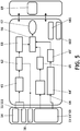
Figure 5 shows the block modules of the system. -
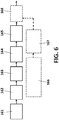
Figure 6 shows a block diagram describing the process to estimate the position and orientation of a wearable module. -
Figure 7 shows an illustration of the type of image recorded by the camera. Height white Pol corresponding to the height infrared LEDs of the visual pattern. - .
Figure 8 shows a non-limiting example of the various frame coordinates used in one embodiment of the invention. -
Figures 9A and 9B represent an example of the acquired data for calculating a base of support. -
Figures 10A and 10B represent an example of a binarised image for calculating a base of support -
Figures 11A and 11B represent an example of the convex hull obtained from the binarised image offigures 10A and 10B . -
Figures 12 shows an example of information used to estimate de SI. - Systems and methods are described for assessing human postural stability based on the measurements and analysis of the simultaneous and relative evolution of at least two parameters of human kinematics and/or kinetics. The same apparatus can be used for training human postural stability. The at least two parameters may be the relative position of the feet (e.g. Base of Support) and the whole human center of mass (CoM) of a person. The at least two parameters may also be the relative position of human center of mass (CoM) with respect to the Center of Pressure (CoP). The parameters may also be the relative position of human center of mass (CoM) with respect to both BoS and CoP.
- Based on the simultaneous measurements of this complementary information, various features are calculated or estimated to be merged and provide a Stability Index (SI) value.
-
Figure 5 shows the block modules of the system and method according to different embodiments. On the left, the blocks corresponding to the hardware components are shown (plantar pressure distribution (also named baropodometric)system 13 53 or alternatively force/ stabilometric platforms 13' or equipment which combines both baropodometric and stabilometric technologies,wearable module 11,reference module 14, and optionally a sensor actuator 16 (for example a servo motor). In the middle, the blocks corresponding to the software components, in charge of processing the information received from the hardware components, thus estimating astability index 67. Also additional blocks forsystem configuration 681 and/ordata management 682 are included. On the right, a block representing thegraphical user interface 69 which enables the user to interact with the system (e.g. data visualization, assessment, training games, etc.). The different embodiments introduced infigure 5 are explained next. -
Figure 1 shows asystem 10 according to a first embodiment of the invention. This system enables to carry out the inventive method. This first embodiment refers to a system for being used to assess and train people during tasks that take place in a limited space where walking is not possible (referred to as "non-nomad"). In this embodiment, the user is allowed to make any activity or motion within a specific platform or surface, that is to say, without leaving that platform or surface. In other words, the user can make dynamic standing activities, such as bending down, on leg balance, and crouching for example. In another embodiment (referred to as "semi-nomad"), the platform covers a larger area and is, therefore, suitable for short walking. - The
system 10 comprises three main parts: at least onereference module 14, at least onewearable device 11 and at least oneplatform 13. It can additional have a remote computer, not illustrated infigure 1 . The computer can be a laptop and runs the main software application which enables to carry out the method of the invention. - The at least one reference signal provided by a
reference module 14 is used. Eachreference module 14 is located at a fixed and known position with a determined orientation. The reference signal can be of one or several physical characteristics such as electromagnetic waves, (ultra) sounds, light, etc. In the particular implementation offigure 1 only onereference module 14 is shown. - In a preferred embodiment, the
reference module 14 is located outside theplatform 13, for example on the floor or on a wall. In an alternative embodiment, thereference system 14 is superimposed or embedded on theplatform 13, as illustrated infigure 1 . - In a preferred embodiment the reference signal uses infrared light. The
reference module 14 providing the reference signal comprises a visual pattern formed by a plurality of infrared sources. In a particular embodiment, it is formed by a plurality of high intensity infrared LEDs mounted on a planar surface. In a non-limiting example, there are eight high intensity infrared LEDs (e.g. conventional elements for example VSMF4720) of dimensions 2.8x3.5x1.75 mm. The elements or items of thepattern 14 can be separated from each other by a distance which can vary between 2 and 20 cm. Power is supplied to the elements of the pattern by either a conventional power supply unit, such as a wall adapter or a battery.Figure 2 represents a schematic view of a pattern of eight elements. - Alternatively, the
visual pattern 14 can be any visual information (e.g. picture, reflective markers, or natural environment) capable of serving as a reference. - The reference module 14 (for example visual pattern) serves as a reference in the subsequent determination of the position of the
wearable devices 11. Since the position of thisreference module 14 and theplatform 13 are known and constant, any position of features estimated from the platform (e.g. Base ofSupport 12, ground reaction force & Centre of Pressure 17) is also known (see sceneTplate later). - The at least one wearable device 11 (also referred to as wearable sensor 11) relates its position and orientation with respect to the platform(s) 13 by means of the reference signals provided by the
reference module 14. The ultimate goal is to relate the position and orientation the Human Center of Mass to information extracted from the platform (e.g. Base of Support and/or Centre of Pressure). Therefore the number and location ofwearable devices 11 must be taken into account especially when considering both system usability and CoM estimation accuracy issues. In general, the more wearable sensors used, the more accurate the CoM position estimation will be. - In a particular embodiment, shown in
figure 1 , there are two wearable devices or sensors 11: one attached to the user's trunk and one attached to the user's arm. In this particular embodiment, they are respectively fixed to a belt and bracelet worn by the user. - As an example, in an embodiment requiring a minimal sensor configuration, a single wearable device might be used. In this case it is preferable to locate it as close as possible to the Center of Mass (CoM) of its wearer: meaning attached to the user's chest or trunk. It can be attached by means of a belt or by means of any conventional alternative fixing or attaching means.
- In a preferred embodiment, the at least one
wearable device 11 is made of a miniaturized (possibly low-cost)camera 11 which is mounted into a box 15 and connected to a processor board (not illustrated) which, in use, is configured for extracting image features in order to estimate the position of the camera based on techniques such as SLAM, or planar Homagraphy (Direct Linear Transform (DLT) algorithm).Figure 3 shows an example of a camera 111 (and its reference frame) mounted into a box 115 (wherein its reference frame is also outlined). The wearable device orsensor 11 is preferably actuated by actuating means 16, such as a servo motor, schematically shown infigures 3 and5 . For example, the orientation of the sensor connected to the body is actuated by at least one servo motor. The at least one servo motor preferably has two DoF (degrees of freedom). The actuating means 16 is used to warranty that the wearable sensor is oriented towards the reference system. - As presented earlier, the preferred embodiment of the
reference module 14 uses an infrared pattern, therefore thecamera 11 embedded into the wearable device is preferably configured for capturing only the infrared light. For these reasons, thecamera 11 preferably comprises a light filter which captures only light information in a certain wavelength range. More preferably, the light filter is an IR band-pass filter centered on 850nm inserted in the mount of the camera between the lens and the image sensor. - Having an infrared
visual pattern 14 and a band-pass IR filter in the camera, the images recorded are almost binary images (white spots or blobs over a black background), thus simplifying the image segmentation and therefore reducing image post-processing time. - In use, when the body segment where the
wearable sensor 11 is attached to is performing an important rotation, it is possible that the wearable sensor(s) is getting less optimally oriented toward the reference signal (in the preferred embodiment it means that thevisual pattern 14 is moving toward an edge of the image captured by the camera). In order not to lose the reception of the reference signal two non-exclusive solutions have been implemented. First, the selection of an optical lens (of the camera 11) that provides a good compromise between the field of view (FOV) and pose estimation accuracy. Second, the use of a lightweight tilt and pan set actuated by micro servos. When the reference signal (e.g. the visual pattern) is about to get outside the field of view of the receiver (e.g. the camera), the servo motors are actuated to better orientate the receiver toward the reference signal. - Optionally, an Inertial Measurement Unit (IMU) can be embedded into the
wearable sensor 11 in order to improve the sensor pose estimation in terms of accuracy but also sampling rate. IMU are composed of 3D accelerometers and gyroscope measuring both the linear acceleration (m.s-2) and angular velocity (rad.s-1) with a sample rate around 1000Hz. Compared to the 30Hz of regular (low cost) camera, the IMU provides measurements and then estimation of the wearable position and orientation between two captured images. In practice we use an extended Kalman filter (EKF) to fuse the vision and inertial measurement [Hol 2011]. The EKF handles the different sample rates. It runs at the high data rate of the IMU and the vision updates are only performed when a new image is available. The IMU gives very accurate short-term predictions of the sensor pose while vision based estimation provides absolute pose estimation (allowing IMU drift cancelation). - The at least one wearable sensor(s) 11 preferably embeds a preferably low cost, low power and small-sized processing board which acquires and sends images or features to a computer (not illustrated) preferably wirelessly.
- The at least one
platform 13 comprises a plurality of sensors (not illustrated infigure 1 ) for measuring the forces/pressures below the user's feet. - In the embodiment shown in
figure 1 there is oneplatform 13. It is preferably a plantar pressure distribution system (also referred to as PPD system and also named baropodometric device). In a preferred embodiment, it comprises an array of M x M sensors (at least a total of 3 sensors) distributed on a certain area (within the dimensions of the platform 13). Each one of these sensors measures the force and or momentum applied on it. In a particular embodiment, in which a conventional PPD system is used, thePPD system 13 comprises 1024 thin-film force sensors (32x32) for a total dimension of 50x50 cm. These devices measure the pressure distribution over the entire plantar surface (matrix type). - In an alternative embodiment, not shown in the figures, instead of using a plantar pressure distribution system, which permits to calculate a base of
support 12, a force plate (or stabilometric platform) is used and allows estimating the Center of Pressure (CoP) and/or ground reaction force (GRF). By combining CoP (and/or GRF) and Center of Mass (CoM), a stability index can be obtained. In other words, the force plate or stabilometric system provides an alternative way of estimating the postural stability of a user. - As a remark, there are systems that combine both baropodometric and stabilometric measurements. There are also sensorized platforms as described above which are not immobile but that can move (e.g. change of orientation).
-
Figure 4 shows asystem 50 according to a second embodiment of the invention. This system also enables to carry out the inventive method. This second embodiment refers to a system for being used with a moving person (also referred to as "semi-nomad"), that is to say, the measurements are taken while the person under examination walks along a sensorised walkway (frontwards or backwards), or a treadmill or similar device. The system either comprises asingle platform 53 which is long enough so as to allow a person to walk on it, or it comprises a plurality ofplatforms 53 preferably disposed in a row. This system differs from the one described in the embodiment referring tofigure 1 in that, while infigure 1 thesystem 10 could work with onereference module 14, thesystem 50 needs at least two reference modules 54 (such as visual patterns) to cover both the "go" and the "return" walks. Thesystem 50 also comprises some hardware components, which are described next, for capturing sensory inputs which are processed. Like in the first embodiment, from the processed signals it is possible to estimate a stability index. This second embodiment represents an approach which can be considered as a natural extension of the first one ("non-nomad approach"). It is an interesting new functionality, as walking postural control mechanisms and skills are different from the ones derived from the limited possibilities of the first embodiment. Like in the first embodiment, the platform orplatforms 53 can be pressure distribution systems (PPD systems), baropodometric devices or force platforms. - The
system 50 also comprises at least one wearable device 51 (sensor device) attached to the user's body, such as a camera, which is similar to thecamera 11 of the former embodiment and also preferably placed into a box and attached the chest of the user. The at least two reference modules 54 are located within thesensor device 51 field of view. Like in the system offigure 1 , the reference modules 54 are preferably infrared visual patterns. There are as many visual patterns as necessary for fulfilling the requirement that always one visual pattern is within the field of view of thewearable device 51. In a possible embodiment, a first visual pattern 54 is located at a first end of the sensorized walkway comprising the platform orplatforms 53 and a second visual pattern 55 is located at a second end (opposite to the first end) of walkway. This allows taking measurements while the person walks back and forth. Alternatively, thesystem 50 can have one or more visual patterns located along one or both sides of the walkway. -
Figure 4 also shows thecomputer 56 which processes the image features provided by the processor board associated to thewearable device 51. Thesystem 50 also preferably comprises a graphical user interface (GUI) not shown infigure 4 , which enables system configuration, data visualization and training games. It is similar to the one described in relation to thesystem 10 offigure 1 . - Next, methods are described for assessing and training the postural stability of a Human body based on complementary information (such as CoM, CoP, BoS) provided by at least two measurement systems that can relate their positions through a reference signal.
- As a generic description based on the scheme of
figure 5 , aStability Index 67 is derived from the relative position and orientation of CoM and from either the BoS or CoP: - 1- CoM position and orientation is estimated 63 from the wearable sensors position and
orientation 62. The wearable sensor position and orientation are estimated 61 with respect to thereference module 14. - 2- BoS is estimated from the
plantar distribution system 13 when available. - 3- CoP is estimated from the
platform 13 when available. - A Stability Index (SI) 67 is obtained by combining the position and orientation of the wearable sensor(s) 11 111 1011 with the Center of Pressure (CoP) and/or the Base of Support (BoS) are/or derived features from them. SI can be expressed as follow:
SI = f (wearable sensor(s) position and orientation, BoS, CoP, GRF, derived features) - The function f allows to (a) combine the information using different techniques, (b) give different importance (weight) to the various inputs, (c) normalize data according to user/patient characteristics. In particular, one or more of said various inputs can be assigned a weight equal to zero, what means that said one or more inputs are not included in the calculation of the SI. However, the information derived from the position and orientation of the wearable sensor(s) 11 111 1011 is always taken into account.
- The center of pressure (CoP) is the point on a body where the total sum of a pressure field acts, causing a force and no moment about that point. The total force vector acting at the center of pressure is the value of the integrated vectorial pressure field. The ground reaction force (GRF) and center of pressure location produce equivalent force and moment on the body as the original pressure field. In postural control assessment, CoP is usually measured with a force platform (planar surface equipped with at least three force and moment transducers). The relevant CoP information is a 2D position (x, y) while its vertical component (z) remains constant.
- The Base of Support (BoS) is defined as the possible range the centre of pressure (CoP) can cover in order to compensate or control movements of the CoM. In principle, the BoS is an area delimited by a perimeter defined by the position of a person's parts of the body (i.e. feet) that are in contact with a supporting surface. In other words, the BoS represent all the points (x, y) within said perimeter.
- The Human Center of Mass (CoM) can be estimated from the position and orientation of the wearable sensor(s). CoM is the unique point where the weighted relative position of the distributed mass sums to zero. In other words, it is the point in an extended body at which the mass of the body may be considered to be concentrated and at which external forces may be considered to be applied. The CoM is represented by a 3D point (x, y, z).
- The method of calculating a stability index is described using a preferred embodiment where the wearable module is made of a camera filtering out the visible light and the visual pattern is made of small infrared emitting LEDs. In one embodiment, a platform providing plantar pressure distribution is used. In another embodiment, a force plate is used.
- Publications have demonstrated the usefulness of both CoM and foot placement to assess human postural stability [Pai 1997]. We describe now how (i) CoM and foot placement (or BoS) are measured, (ii) how these two positions are related and (iii) how they are combined into a stability index, later on used for assessment or training purposes.
- As an illustrative example, in an embodiment requiring a minimal sensor configuration, a single wearable device is used and attached to the chest. A method is described, that allows the estimation of the wearable sensor position and orientation. This is then used to estimate the
CoM position 63 where, in a possible embodiment and as a first approach, a series of homogeneous spatial transformations are applied. For that purpose a set of coordinate systems is defined, as well as homogenous coordinate transformations between these coordinated systems. A homogeneous coordinate transformation matrix is represented as bold letter T. - The coordinate system from which the transformation is applied is represented by a lower case subscript which appears after the matrix symbol. The resulting coordinate system is denoted by lower case superscript which precedes the symbol. Vectors will be illustrated with capital letter preceded by a lower case superscript which represents the coordinate system in which they are expressed. For example ( scene COM ) is the Center of Mass vector (x,y,z) expressed in the scene coordinates.
- The various reference frames are illustrated on
figure 8 . The concerned transformations are the following: - scene T cam: from Camera (1011) to Scene reference frame (1014)
- cam T box: from Box Point of Interest (1015) to Camera (1011)
- box T sac: from Human Sacrum (116) to Box Point of Interest (1015)
- sac T com: from Human CoM (163) to Human Sacrum (116)
- scene T plat: from Platform (1013) to Scene reference frame (1014)
- The final goal is to estimate the CoM position and orientation expressed in the scene reference frame 1014 ( scene COM ). It can be expressed in the following manner:

- From the above equation most transformation matrices are known:
cam T box: Known but can vary over time. Based on the mechanical design of thewearable sensor 1011 and the known orientation of the servo motors as shown infigure 9A , which shows the rigid transformation applied relating the position and orientation of the origin of thecamera 1011 with respect to a point of interest of thebox 1015. - box T sac: Known and fixed.
Wearable sensors 1011 are positioned at a known location with respect to thesacrum 116 of the subject. - sac T com: Model learned from motion analysis data sets.
- scene T plat: Known and fixed position of the
platform 1013 with respect to the reference module 1014. If needed, a wearable sensor (14) can also be placed on the platform in order to measure its position with respect to the reference module. - Then only scene T cam is unknown and has to be estimated at every moment.
- Estimating the position and orientation of the
camera 1011 in the scene coordinates (scene T cam) requires a model of the image formation process. Such a model is expressed as a composition of the intrinsic (K), extrinsic camera (scene T cam) parameters and projection matrix P 0 of the camera leading to


- In order to estimate camTscene from
Equation 2, the strategy is to have a known pattern (composed of point or any 3d features, known in term of dimension, location...), and apply a process to extract from the image the projection of this pattern. The example we provide now is an illustration of how it can be done: vector scenePOI is known and corresponds to the pattern described infigure 2 . Vector camPOI is estimated from the image provided by the camera pointing toward the reference pattern (seefigure 9A ). Among other possibilities it can be achieved by applying the following process (outlined infigure 6 ). - As outlined in
figure 6 , from the images provided by thecamera 11 1011 at a predefined rate (for example, 30 pictures per second or more) afirst preprocessing 161 is applied, transforming the input image (usually composed of three channels when considering color images or on1 channel when considering gray-level images) into a single one (e.g. by keeping one channel or combining several ones). This is preferably done in order to decrease the processing time while keeping most of the information. A thresholding process is further and preferably applied for image binarisation. A compromise must be considered: if the threshold applied is very low, too much noise can be introduced in the image. On the other hand, if it is very high, it can cause information losses. - The binary image extracted should only contain points (Pol) corresponding to the height infrared LEDs of the visual pattern (
figure 7 ). - It might happen that additional elements are still present in the image. It is therefore preferable to detect 162 the region of interest (Rol), being the area where a concentration of points is expected. First a closing operation is applied to the whole image with an appropriate number of steps to assure that the different image points get merged. Among several potential Rols, the Rol selected is the one that matches constraint related to its size and shape and temporal consistency (meaning that Region of Interests at time t and t+1 frame are spatially close).
- Once the Rol is selected it is then possible to detect 163 the location, in the image, of the point of interest (Pol).
- When Pol are localised 163, they are reordered 164 (see for example
figure 2 ). - Once the Pols have been reordered 164, the camera pose (sceneTcam) is estimated 165 using a minimisation process (extrinsic parameters estimation). In this process, the vector scenePOI is re-projected onto the camera reference frame


Equation 1. In parallel to the camera position andorientation estimation 165,complementary measurements 166 can be performed inside the wearable device in order to estimate its relative motion 167 (e.g. incremental translation and rotation) and therefore refine the camera position andorientation estimation 165 by fusing both sources ofinformation 168. - In a possible embodiment the following measurements are additionally taken: the sensor acceleration and/or the sensor angular velocity and/or the magnetic orientation of the sensor. If these additional measurements are taken, the estimation of the relative position of the
sensor 11 111 1011 can be refined 168 as follows: First, the acceleration and/or angular velocity and/or magnetic orientation of the sensor is acquired 166; then the sensor relative translation and orientation is estimated 167; finally the estimation of the sensor position and orientation is refined 168 by combining theinitial estimation 165 with the additional information available. - The output of the minimisation process (extrinsic parameters estimation) 165 (168 if available) is sceneTcam. From sceneTcam , sceneCOM is then computed using the
Equation 1. One innovation of this disclosure is to relate the position of the Human CoM ( sceneCOM) or other body parts to foot related information (e.g. BoS, CoP). - For that purpose and as represented in the block diagram of
figure 5 , if a plantar pressure distribution system or abaropodometric system 13 53 is used, a base of support BoS can be calculated (blocks 64, 65). Conventional platforms provide, through a software API (e.g. a dll file), real-time access to the data. In this case it is a matrix
-
Figures 9A and 9B represent an example of the acquired data for respectively one foot and two feet. In a particular implementation, the information is stored in a 32x32 matrix. - Next the extraction of the BoS (stage 65) is described: Once acquired this pressure data matrix, a binarisation function is applied with a certain threshold. The threshold value is defined in order to discard sensor noise (pressure below threshold is reassigned to zero) and assign a value of one when a real pressure is applied.
Figures 10A and 10B represent an example of the binarised image for respectively one foot and two feet. - Once the image is binary, a function for calculating the convex hull of the points is executed. A convex hull of a set X of points in the Euclidean plane is the smallest convex set that contains X. The BoS is obtained from the points ( platBOS) describing the convex hull (stage 65).
Figures 11A and 11B represent an example of the convex hull obtained from the binarised image. Knowing the physical dimension of the sensor cell, the position of BoS points ( platBOS) are converted into a metric dimension (e.g meters) and are expressed in the reference frame of the platform. Finally, the sequence of points is expressed in the scene reference frame by applying the following transformation:
- Note that from the plantar pression distribution matrix is it possible to extract a so called Centre of Force (CoF) defined as the barycentric coordinate considering that each sensor i has a spatial position (xi, yi ) and pressure value Pi:

- With

- Similarly sceneCOF = sceneTplat · plat COF
- If, alternatively, a force plate or a stabilometric system 13' is used, the system delivers 6 DoF measurements: 3D ground reaction forces


- At
stage 66 infigure 5 , all measurements are expressed in the scene reference frame: sceneCOM; sceneBOS; sceneCOF; sceneCOP, sceneGRF. It is therefore possible to analyse 66 the relative positions and evolution of these human postural stability descriptors and create astability Index 67. It is important to note again that depending of the platform used one may have access to sceneBOS only or scene COP only or both. This is why SI is expressed as follows:
SI = f (wearable sensor(s) position and orientation, BoS, CoP, GRF, derived features) Where function f allows to (a) combine the information using different techniques, (b) give different importance (weight) to the various inputs, (c) normalize data according to user/patient characteristics. In particular, one or more of said various inputs can be assigned a weight equal to zero, what means that said one or more inputs are not included in the calculation of the SI. However, the information derived from the position and orientation of the wearable sensor(s) 11 111 1011 is always taken into account. - As an example, if CoP is not available, the function f will assign zero to the weight associated with CoP (e.g.).

-
Figures 12 shows an example of the information used to estimate de SI. In this case, the Center of Mass (CoM), the vertical projection of the Center of Mass (CoMv) and the Base of Support (BoS) are used. - Finally, the software and graphical user interface mentioned in the present disclosure is used to (1) visualize instantaneously the measurements performed (e.g. position(s) of the wearable sensor(s), BoS, CoP ,CoM, SI), (2) store/retrieve past recording, (3) guide the user (patient or professional) to run an assessment procedure, (4) engage the user into a training procedure (e.g. impose user foot placement and then request the user to follow a path with his/her Center of Mass, train CoM-CoP distance).
- The stability index has many applications. For example, a doctor or clinician can evaluate from it the evolution of the patient or his/her lack of stability. For this purpose standard tests such as Romberg test, Functional Reach Test (FRT), Short Form Berg Balance Scale (SF-BBS), One-leg stance test, "Balance part" of the Tinetti Performance Oriented Mobility Assessment (POMA), Nudge Test, Postural Stress Test (PST) can be performed while using the system and method of the present disclosure.
- During the execution of the test, the clinician sees on graphical user interface the real-time evolution of relevant parameters (e.g. CoM, BoS, CoP, or derived features) and/or the stability index itself. After completion of the test, a report is generated with plots, tables of values, etc.
- In addition, specific and new training sessions can also be prescribed using the possibility to jointly measure and feedback information about both CoM and foot placement. As an example, the software application will ask the user to position their feet at a specific location on the platform. The user sees on the GUI the targeted foot placement and tries to match these positions. A real-time visual feedback of the current feet positions is provided. When feet positions match the targets (normal, semi-tandem, tandem, others) the user is instructed not to move its feet and to move its CoM in order to follow a spiral path. The execution time is recorded as well as a score that is based on the number of time the CoM goes out of the path for example.
- With the described system and method for assessing human postural stability based on the measurements and analysis of the simultaneous and relative evolution of at least two parameters of Human kinematics and/or kinetics, a stability index can be obtained from a parameter related to the center of mass (CoM) of a person and at least one parameter related to the relative position of the feet (e.g. Base of Support) or the Center of Pressure (CoP) of the person.
- Please note that in this document, the term "comprises" and its derivations (such as "comprising", etc.) should not be understood in an excluding sense, that is, these terms should not be interpreted as excluding the possibility that what is described and defined may include further elements, steps, etc.
- On the other hand, the invention is obviously not limited to the specific embodiment(s) described herein, but also encompasses any variations that may be considered by any person skilled in the art (for example, as regards the choice of materials, dimensions, components, configuration, etc.), within the scope of the invention as defined in the claims.
Claims (13)
- A system comprising:- at least one platform (13, 53, 13') configured for, in use, having a person on it, said platform (13, 53, 13') comprising a plurality of sensors configured for capturing information of forces/pressures applied by the feet of the person or of the position of the person's feet;- means for, from said captured information, respectively extracting (65, 65') either a center of pressure or the position of the feet;- at least one reference module (14) disposed at a fixed location with respect to said platform (13, 53, 13');- at least one sensor (11 111 1011) which, in use, is connected to the body of the person situated on said platform (13, 53, 13'), the sensor being configured for capturing at least one reference signal provided by said at least one reference module (14);the system (10, 20) further comprising:- processing means for extracting information from said at least one captured reference signal and for estimating (63) from said reference signal the position and orientation of said at least one sensor with respect to the at least one reference module;- processing means for estimating the position and orientation of the body of said person from said determined position and orientation of the at least one sensor in turn obtained from said at least one reference signal;- processing means for calculating a stability index (67) from said position and orientation of the body of said person and from said extracted feet position or center of pressure.
- The system of claim 1, wherein said at least one sensor connected to the body of the person situated on said platform (13, 53, 13') comprises a camera (11) and said at least one reference signal provided by said at least one reference module disposed at a fixed location with respect to said platform (13, 53, 13') is a visual pattern (14, 54).
- The system of claim 2, wherein said at least one visual pattern (14) is an infrared visual pattern and said at least one camera (11) is configured to capture images in the infrared range of light.
- The system of any preceding claim, wherein said platform is a plantar pressure distribution system (13, 53) or a force platform (13').
- The system of any preceding claim, wherein said stability index (67) is a function of the position and orientation of said at least one sensor connected to the body of the person situated on said platform (13, 53, 13') and at least one of the following inputs: a base of support (BoS), a center of pressure (CoP), a ground reaction force (GRF) and one or more features derived from said inputs.
- The system of any preceding claim, wherein said at least one sensor connected to the body of the person situated on said platform (13, 53, 13') is adapted to be connected to the trunk of said person.
- The system of any preceding claim, wherein said at least one sensor connected to the body of the person situated on said platform (13, 53, 13') comprises at least one acceleration transducer for measuring the sensor acceleration or at least one angular velocity transducer for measuring the sensor angular velocity.
- The system of any preceding claim, wherein said at least one reference module is placed on or outside said platform (13, 53).
- The system of any preceding claim, wherein the orientation of the at least one sensor connected to the body is actuated by at least one servo motor.
- A method to obtain a stability index of a person, comprising the steps:- by means of a plurality of sensors located at a platform (13, 53, 13') on which a person is situated, capturing information of the pressure applied by the feet of the person or of the position of the person's feet;- from said captured information, respectively extracting (65, 65') either a center of pressure or a feet position;- by means of at least one sensor connected to the body of the person situated on said platform (13, 53, 13'), capturing at least one reference signal provided by at least one reference module disposed at a fixed location with respect to said platform (13, 53, 13');the method further comprising the steps of:- extracting by processing means information from said at least one captured reference signal;- from said reference signal, estimating (62, 165) by processing means the position and orientation of said at least one sensor with respect to the at least one reference module;- from said determined position and orientation of said at least one sensor, estimating by processing means the position and orientation of the body of said person (63);- calculating by processing means a stability index (67) from said position and orientation of the body of said person and from said extracted feet position or center of pressure.
- The method of claim 10, wherein said stage of estimating (63) the position and orientation of the body of said person is done as follows:- extracting (61) a point of interest from said at least one image;- estimating (62) the relative position of the sensor (11, 111, 1011) with respect to the visual pattern (14) and the orientation of the sensor (11, 111, 1011);- estimating (63) the center of mass (CoM) of the person from said relative position and orientation of the sensor (11, 111, 1011).
- The method of either claim 10 or 11, further comprising the step of measuring the sensor acceleration and/or the sensor angular velocity and/or the magnetic orientation of the sensor.
- The method of claim 12, wherein said stage of estimating (62) the position and orientation of the at least one sensor (11 111) is refined (168) as follows:- acquiring (166) the acceleration and/or angular velocity and/or magnetic orientation of the sensor;- estimating (167) the sensor relative translation and orientation;- refining (168) the estimation of the sensor position and orientation by combining the initial estimation (165) with the additional information available (167).
Priority Applications (4)
| Application Number | Priority Date | Filing Date | Title |
|---|---|---|---|
| ES14382441T ES2892354T3 (en) | 2014-11-06 | 2014-11-06 | Method and system for the evaluation of functional balance |
| EP14382441.5A EP3017761B1 (en) | 2014-11-06 | 2014-11-06 | System for functional balance assessment |
| CA2911537A CA2911537A1 (en) | 2014-11-06 | 2015-11-05 | Method and system for functional balance assessment |
| US14/934,531 US10376222B2 (en) | 2014-11-06 | 2015-11-06 | Method and system for functional balance assessment |
Applications Claiming Priority (1)
| Application Number | Priority Date | Filing Date | Title |
|---|---|---|---|
| EP14382441.5A EP3017761B1 (en) | 2014-11-06 | 2014-11-06 | System for functional balance assessment |
Publications (2)
| Publication Number | Publication Date |
|---|---|
| EP3017761A1 EP3017761A1 (en) | 2016-05-11 |
| EP3017761B1 true EP3017761B1 (en) | 2021-07-21 |
Family
ID=51900834
Family Applications (1)
| Application Number | Title | Priority Date | Filing Date |
|---|---|---|---|
| EP14382441.5A Active EP3017761B1 (en) | 2014-11-06 | 2014-11-06 | System for functional balance assessment |
Country Status (4)
| Country | Link |
|---|---|
| US (1) | US10376222B2 (en) |
| EP (1) | EP3017761B1 (en) |
| CA (1) | CA2911537A1 (en) |
| ES (1) | ES2892354T3 (en) |
Families Citing this family (12)
| Publication number | Priority date | Publication date | Assignee | Title |
|---|---|---|---|---|
| KR20160075118A (en) * | 2014-12-19 | 2016-06-29 | 한국산업기술대학교산학협력단 | System for Estimating the Center of Pressure in Gait Rehabilitation Robots and method thereof |
| US11030918B2 (en) * | 2015-09-10 | 2021-06-08 | Kinetic Telemetry, LLC | Identification and analysis of movement using sensor devices |
| US20170258388A1 (en) * | 2016-03-08 | 2017-09-14 | Ana Cecilia Gomez del Campo | Devices and methods for measuring balance |
| KR101813043B1 (en) * | 2016-09-30 | 2017-12-28 | 대한민국 | Balance ability evaluation and training method using righting reflex |
| KR102093185B1 (en) * | 2017-12-28 | 2020-03-25 | (주)맨엔텔 | Berg balance testing apparatus and method for the same |
| US11007398B2 (en) * | 2018-05-14 | 2021-05-18 | Florida Institute For Human & Machine Cognition, Inc. | Parallel cable exercise device |
| CN108968965A (en) * | 2018-06-11 | 2018-12-11 | 郑州大学 | Portable body balance evaluation and test training system |
| RU2692148C1 (en) * | 2018-06-22 | 2019-06-21 | Юрий Иванович Колягин | Device for diagnosing postural disorders |
| IT201800010151A1 (en) * | 2018-11-08 | 2020-05-08 | Tecnobody S R L | ROBOTIC PROPRIOCEPTIVE-POSTURAL SYSTEM WITH INTEGRATED THREE-DIMENSIONAL CAMERA |
| EP3785627A1 (en) * | 2019-08-29 | 2021-03-03 | Politechnika Lodzka | A device and a method for dynamic posturography |
| KR102460802B1 (en) * | 2019-10-18 | 2022-10-31 | 주식회사 네오펙트 | Apparatus for sensing, method and program for processing sensing data |
| CN111297577B (en) * | 2020-02-19 | 2022-03-01 | 郑州大学体育学院 | Intelligent seat integrating tumble risk prediction and tumble resistance training |
Citations (1)
| Publication number | Priority date | Publication date | Assignee | Title |
|---|---|---|---|---|
| WO1999053838A1 (en) * | 1998-04-17 | 1999-10-28 | Massachusetts Institute Of Technology | Motion tracking system |
Family Cites Families (26)
| Publication number | Priority date | Publication date | Assignee | Title |
|---|---|---|---|---|
| US5744953A (en) * | 1996-08-29 | 1998-04-28 | Ascension Technology Corporation | Magnetic motion tracker with transmitter placed on tracked object |
| EP1527734A4 (en) | 2002-08-09 | 2009-04-15 | Panasonic Corp | Balance state analysis device |
| JP4471588B2 (en) | 2003-05-22 | 2010-06-02 | 有限会社ジーエムアンドエム | Equilibrium sensory function diagnostic system and apparatus used therefor |
| US7292151B2 (en) * | 2004-07-29 | 2007-11-06 | Kevin Ferguson | Human movement measurement system |
| EP2004054A2 (en) * | 2006-04-10 | 2008-12-24 | Arneborg Ernst | Portable balance function diagnostic system |
| GB2438167A (en) | 2006-05-19 | 2007-11-21 | Univ Teesside | Balance monitor |
| KR100702898B1 (en) * | 2006-05-29 | 2007-04-03 | 경북대학교 산학협력단 | Gait training system using motion analysis |
| JP2009020780A (en) * | 2007-07-13 | 2009-01-29 | Fujitsu Ltd | Storage control program, storage control apparatus and storage control method |
| US9526946B1 (en) * | 2008-08-29 | 2016-12-27 | Gary Zets | Enhanced system and method for vibrotactile guided therapy |
| DE102007049323A1 (en) * | 2007-10-15 | 2009-04-23 | Zebris Medical Gmbh | Vertebrate movement analyzing device for use with treadmill, has signal processing stage processing output signals of base sensor for calibrating and correcting signal processing of output signals of pressure/force sensors |
| US20090137933A1 (en) | 2007-11-28 | 2009-05-28 | Ishoe | Methods and systems for sensing equilibrium |
| US7997405B2 (en) | 2009-07-22 | 2011-08-16 | Arrowhead Systems, Inc. | Sanitary conveyor |
| JP5392671B2 (en) * | 2008-12-02 | 2014-01-22 | 学校法人早稲田大学 | Walking measurement device |
| US8845556B1 (en) * | 2009-03-06 | 2014-09-30 | Pamela Schickler | Method and apparatus for body balance and alignment correction and measurement |
| US8876739B2 (en) | 2009-07-24 | 2014-11-04 | Oregon Health & Science University | System for clinical assessment of movement disorders |
| JP5628560B2 (en) | 2010-06-02 | 2014-11-19 | 富士通株式会社 | Portable electronic device, walking trajectory calculation program, and walking posture diagnosis method |
| FR2966336B1 (en) * | 2010-10-21 | 2013-12-27 | Univ De Technologies De Troyes | EQUILIBRIUM QUALITY ASSESSMENT PROCESS, DEVICE AND SYSTEM |
| US8448056B2 (en) * | 2010-12-17 | 2013-05-21 | Microsoft Corporation | Validation analysis of human target |
| CA2851443C (en) * | 2011-10-09 | 2022-07-12 | The Medical Research, Infrastructure and Health Services Fund of the Tel Aviv Medical Center | Virtual reality for movement disorder diagnosis and/or treatment |
| BR112014017678B1 (en) * | 2012-01-20 | 2021-10-26 | Naf Ab | PNEUMATICLY ACTIONABLE VALVE ACTUATOR AND METHOD OF BLOCKING A VALVE CLOSING ELEMENT IN RELATION TO A VALVE BODY |
| US20130296740A1 (en) * | 2012-05-07 | 2013-11-07 | Kent S. Greenawalt | Method and Apparatus for Analyzing Foot Arch Deterioration |
| DE102012212115B3 (en) * | 2012-07-11 | 2013-08-14 | Zebris Medical Gmbh | Treadmill assembly and method of operating such |
| US10258257B2 (en) * | 2012-07-20 | 2019-04-16 | Kinesis Health Technologies Limited | Quantitative falls risk assessment through inertial sensors and pressure sensitive platform |
| WO2014160451A1 (en) * | 2013-03-13 | 2014-10-02 | Virtusense Technologies | Range of motion system, and method |
| US9801568B2 (en) * | 2014-01-07 | 2017-10-31 | Purdue Research Foundation | Gait pattern analysis for predicting falls |
| US20150208975A1 (en) * | 2014-01-29 | 2015-07-30 | Sync-Think, Inc. | System and Method for Target Independent Neuromotor Analytics |
-
2014
- 2014-11-06 ES ES14382441T patent/ES2892354T3/en active Active
- 2014-11-06 EP EP14382441.5A patent/EP3017761B1/en active Active
-
2015
- 2015-11-05 CA CA2911537A patent/CA2911537A1/en not_active Abandoned
- 2015-11-06 US US14/934,531 patent/US10376222B2/en not_active Expired - Fee Related
Patent Citations (1)
| Publication number | Priority date | Publication date | Assignee | Title |
|---|---|---|---|---|
| WO1999053838A1 (en) * | 1998-04-17 | 1999-10-28 | Massachusetts Institute Of Technology | Motion tracking system |
Also Published As
| Publication number | Publication date |
|---|---|
| EP3017761A1 (en) | 2016-05-11 |
| US20160128642A1 (en) | 2016-05-12 |
| CA2911537A1 (en) | 2016-05-06 |
| US10376222B2 (en) | 2019-08-13 |
| ES2892354T3 (en) | 2022-02-03 |
Similar Documents
| Publication | Publication Date | Title |
|---|---|---|
| EP3017761B1 (en) | System for functional balance assessment | |
| CN107080540B (en) | System and method for analyzing gait and postural balance of a person | |
| US8165844B2 (en) | Motion tracking system | |
| Monnet et al. | Measurement of three-dimensional hand kinematics during swimming with a motion capture system: a feasibility study | |
| Weenk et al. | Ambulatory estimation of relative foot positions by fusing ultrasound and inertial sensor data | |
| KR101118654B1 (en) | rehabilitation device using motion analysis based on motion capture and method thereof | |
| Miezal et al. | Real-time inertial lower body kinematics and ground contact estimation at anatomical foot points for agile human locomotion | |
| Monoli et al. | Land and underwater gait analysis using wearable IMU | |
| Surer et al. | Methods and technologies for gait analysis | |
| Yagi et al. | Gait measurement at home using a single RGB camera | |
| US20110166821A1 (en) | System and method for analysis of ice skating motion | |
| EP2023816B1 (en) | Balance monitor | |
| Duncan et al. | Camera-Based Short Physical Performance Battery and Timed Up and Go Assessment for Older Adults with Cancer | |
| Yang et al. | Empowering a gait feature-rich timed-up-and-go system for complex ecological environments | |
| CN115530815A (en) | Gait time phase recognition method based on angular velocity sensor | |
| Wei et al. | Center of mass estimation for balance evaluation using convolutional neural networks | |
| US11497452B2 (en) | Predictive knee joint loading system | |
| Meigal et al. | Analysis of human gait based on smartphone inertial measurement unit: a feasibility study | |
| KR20230120341A (en) | 3D human body joint angle prediction method and system using 2D image | |
| KR102229071B1 (en) | Apparatus for implementing motion using piezoelectric sensor and method thereof | |
| Ippisch et al. | mVEGAS–mobile smartphone-based spatiotemporal gait analysis in healthy and ataxic gait disorders | |
| Vilas et al. | Gait Analysis in Hereditary Amyloidosis Associated to Variant Transthyretin | |
| Nguyen et al. | A method for estimating text neck while walking using a 3-axis accelerometer | |
| Okkalidis et al. | A review of foot pose and trajectory estimation methods using inertial and auxiliary sensors for kinematic gait analysis | |
| US20240130636A1 (en) | Apparatus and method for motion capture |
Legal Events
| Date | Code | Title | Description |
|---|---|---|---|
| PUAI | Public reference made under article 153(3) epc to a published international application that has entered the european phase |
Free format text: ORIGINAL CODE: 0009012 |
|
| AK | Designated contracting states |
Kind code of ref document: A1 Designated state(s): AL AT BE BG CH CY CZ DE DK EE ES FI FR GB GR HR HU IE IS IT LI LT LU LV MC MK MT NL NO PL PT RO RS SE SI SK SM TR |
|
| AX | Request for extension of the european patent |
Extension state: BA ME |
|
| STAA | Information on the status of an ep patent application or granted ep patent |
Free format text: STATUS: REQUEST FOR EXAMINATION WAS MADE |
|
| 17P | Request for examination filed |
Effective date: 20161102 |
|
| RBV | Designated contracting states (corrected) |
Designated state(s): AL AT BE BG CH CY CZ DE DK EE ES FI FR GB GR HR HU IE IS IT LI LT LU LV MC MK MT NL NO PL PT RO RS SE SI SK SM TR |
|
| GRAP | Despatch of communication of intention to grant a patent |
Free format text: ORIGINAL CODE: EPIDOSNIGR1 |
|
| STAA | Information on the status of an ep patent application or granted ep patent |
Free format text: STATUS: GRANT OF PATENT IS INTENDED |
|
| INTG | Intention to grant announced |
Effective date: 20210211 |
|
| GRAS | Grant fee paid |
Free format text: ORIGINAL CODE: EPIDOSNIGR3 |
|
| GRAA | (expected) grant |
Free format text: ORIGINAL CODE: 0009210 |
|
| STAA | Information on the status of an ep patent application or granted ep patent |
Free format text: STATUS: THE PATENT HAS BEEN GRANTED |
|
| AK | Designated contracting states |
Kind code of ref document: B1 Designated state(s): AL AT BE BG CH CY CZ DE DK EE ES FI FR GB GR HR HU IE IS IT LI LT LU LV MC MK MT NL NO PL PT RO RS SE SI SK SM TR |
|
| REG | Reference to a national code |
Ref country code: GB Ref legal event code: FG4D |
|
| REG | Reference to a national code |
Ref country code: CH Ref legal event code: EP |
|
| REG | Reference to a national code |
Ref country code: DE Ref legal event code: R096 Ref document number: 602014078868 Country of ref document: DE |
|
| REG | Reference to a national code |
Ref country code: AT Ref legal event code: REF Ref document number: 1411835 Country of ref document: AT Kind code of ref document: T Effective date: 20210815 |
|
| REG | Reference to a national code |
Ref country code: IE Ref legal event code: FG4D |
|
| REG | Reference to a national code |
Ref country code: LT Ref legal event code: MG9D |
|
| REG | Reference to a national code |
Ref country code: NL Ref legal event code: MP Effective date: 20210721 |
|
| REG | Reference to a national code |
Ref country code: AT Ref legal event code: MK05 Ref document number: 1411835 Country of ref document: AT Kind code of ref document: T Effective date: 20210721 |
|
| PG25 | Lapsed in a contracting state [announced via postgrant information from national office to epo] |
Ref country code: PT Free format text: LAPSE BECAUSE OF FAILURE TO SUBMIT A TRANSLATION OF THE DESCRIPTION OR TO PAY THE FEE WITHIN THE PRESCRIBED TIME-LIMIT Effective date: 20211122 Ref country code: NO Free format text: LAPSE BECAUSE OF FAILURE TO SUBMIT A TRANSLATION OF THE DESCRIPTION OR TO PAY THE FEE WITHIN THE PRESCRIBED TIME-LIMIT Effective date: 20211021 Ref country code: NL Free format text: LAPSE BECAUSE OF FAILURE TO SUBMIT A TRANSLATION OF THE DESCRIPTION OR TO PAY THE FEE WITHIN THE PRESCRIBED TIME-LIMIT Effective date: 20210721 Ref country code: FI Free format text: LAPSE BECAUSE OF FAILURE TO SUBMIT A TRANSLATION OF THE DESCRIPTION OR TO PAY THE FEE WITHIN THE PRESCRIBED TIME-LIMIT Effective date: 20210721 Ref country code: LT Free format text: LAPSE BECAUSE OF FAILURE TO SUBMIT A TRANSLATION OF THE DESCRIPTION OR TO PAY THE FEE WITHIN THE PRESCRIBED TIME-LIMIT Effective date: 20210721 Ref country code: BG Free format text: LAPSE BECAUSE OF FAILURE TO SUBMIT A TRANSLATION OF THE DESCRIPTION OR TO PAY THE FEE WITHIN THE PRESCRIBED TIME-LIMIT Effective date: 20211021 Ref country code: AT Free format text: LAPSE BECAUSE OF FAILURE TO SUBMIT A TRANSLATION OF THE DESCRIPTION OR TO PAY THE FEE WITHIN THE PRESCRIBED TIME-LIMIT Effective date: 20210721 Ref country code: HR Free format text: LAPSE BECAUSE OF FAILURE TO SUBMIT A TRANSLATION OF THE DESCRIPTION OR TO PAY THE FEE WITHIN THE PRESCRIBED TIME-LIMIT Effective date: 20210721 Ref country code: SE Free format text: LAPSE BECAUSE OF FAILURE TO SUBMIT A TRANSLATION OF THE DESCRIPTION OR TO PAY THE FEE WITHIN THE PRESCRIBED TIME-LIMIT Effective date: 20210721 Ref country code: RS Free format text: LAPSE BECAUSE OF FAILURE TO SUBMIT A TRANSLATION OF THE DESCRIPTION OR TO PAY THE FEE WITHIN THE PRESCRIBED TIME-LIMIT Effective date: 20210721 |
|
| REG | Reference to a national code |
Ref country code: ES Ref legal event code: FG2A Ref document number: 2892354 Country of ref document: ES Kind code of ref document: T3 Effective date: 20220203 |
|
| PG25 | Lapsed in a contracting state [announced via postgrant information from national office to epo] |
Ref country code: PL Free format text: LAPSE BECAUSE OF FAILURE TO SUBMIT A TRANSLATION OF THE DESCRIPTION OR TO PAY THE FEE WITHIN THE PRESCRIBED TIME-LIMIT Effective date: 20210721 Ref country code: LV Free format text: LAPSE BECAUSE OF FAILURE TO SUBMIT A TRANSLATION OF THE DESCRIPTION OR TO PAY THE FEE WITHIN THE PRESCRIBED TIME-LIMIT Effective date: 20210721 Ref country code: GR Free format text: LAPSE BECAUSE OF FAILURE TO SUBMIT A TRANSLATION OF THE DESCRIPTION OR TO PAY THE FEE WITHIN THE PRESCRIBED TIME-LIMIT Effective date: 20211022 |
|
| REG | Reference to a national code |
Ref country code: DE Ref legal event code: R097 Ref document number: 602014078868 Country of ref document: DE |
|
| PG25 | Lapsed in a contracting state [announced via postgrant information from national office to epo] |
Ref country code: DK Free format text: LAPSE BECAUSE OF FAILURE TO SUBMIT A TRANSLATION OF THE DESCRIPTION OR TO PAY THE FEE WITHIN THE PRESCRIBED TIME-LIMIT Effective date: 20210721 |
|
| PLBE | No opposition filed within time limit |
Free format text: ORIGINAL CODE: 0009261 |
|
| STAA | Information on the status of an ep patent application or granted ep patent |
Free format text: STATUS: NO OPPOSITION FILED WITHIN TIME LIMIT |
|
| PG25 | Lapsed in a contracting state [announced via postgrant information from national office to epo] |
Ref country code: SM Free format text: LAPSE BECAUSE OF FAILURE TO SUBMIT A TRANSLATION OF THE DESCRIPTION OR TO PAY THE FEE WITHIN THE PRESCRIBED TIME-LIMIT Effective date: 20210721 Ref country code: SK Free format text: LAPSE BECAUSE OF FAILURE TO SUBMIT A TRANSLATION OF THE DESCRIPTION OR TO PAY THE FEE WITHIN THE PRESCRIBED TIME-LIMIT Effective date: 20210721 Ref country code: RO Free format text: LAPSE BECAUSE OF FAILURE TO SUBMIT A TRANSLATION OF THE DESCRIPTION OR TO PAY THE FEE WITHIN THE PRESCRIBED TIME-LIMIT Effective date: 20210721 Ref country code: EE Free format text: LAPSE BECAUSE OF FAILURE TO SUBMIT A TRANSLATION OF THE DESCRIPTION OR TO PAY THE FEE WITHIN THE PRESCRIBED TIME-LIMIT Effective date: 20210721 Ref country code: CZ Free format text: LAPSE BECAUSE OF FAILURE TO SUBMIT A TRANSLATION OF THE DESCRIPTION OR TO PAY THE FEE WITHIN THE PRESCRIBED TIME-LIMIT Effective date: 20210721 Ref country code: AL Free format text: LAPSE BECAUSE OF FAILURE TO SUBMIT A TRANSLATION OF THE DESCRIPTION OR TO PAY THE FEE WITHIN THE PRESCRIBED TIME-LIMIT Effective date: 20210721 |
|
| 26N | No opposition filed |
Effective date: 20220422 |
|
| PG25 | Lapsed in a contracting state [announced via postgrant information from national office to epo] |
Ref country code: MC Free format text: LAPSE BECAUSE OF FAILURE TO SUBMIT A TRANSLATION OF THE DESCRIPTION OR TO PAY THE FEE WITHIN THE PRESCRIBED TIME-LIMIT Effective date: 20210721 |
|
| PG25 | Lapsed in a contracting state [announced via postgrant information from national office to epo] |
Ref country code: LU Free format text: LAPSE BECAUSE OF NON-PAYMENT OF DUE FEES Effective date: 20211106 Ref country code: BE Free format text: LAPSE BECAUSE OF NON-PAYMENT OF DUE FEES Effective date: 20211130 |
|
| REG | Reference to a national code |
Ref country code: BE Ref legal event code: MM Effective date: 20211130 |
|
| PG25 | Lapsed in a contracting state [announced via postgrant information from national office to epo] |
Ref country code: IE Free format text: LAPSE BECAUSE OF NON-PAYMENT OF DUE FEES Effective date: 20211106 |
|
| PGFP | Annual fee paid to national office [announced via postgrant information from national office to epo] |
Ref country code: GB Payment date: 20220919 Year of fee payment: 9 |
|
| PGFP | Annual fee paid to national office [announced via postgrant information from national office to epo] |
Ref country code: IT Payment date: 20221123 Year of fee payment: 9 Ref country code: DE Payment date: 20221125 Year of fee payment: 9 |
|
| PGFP | Annual fee paid to national office [announced via postgrant information from national office to epo] |
Ref country code: CH Payment date: 20221205 Year of fee payment: 9 |
|
| PG25 | Lapsed in a contracting state [announced via postgrant information from national office to epo] |
Ref country code: HU Free format text: LAPSE BECAUSE OF FAILURE TO SUBMIT A TRANSLATION OF THE DESCRIPTION OR TO PAY THE FEE WITHIN THE PRESCRIBED TIME-LIMIT; INVALID AB INITIO Effective date: 20141106 |
|
| PG25 | Lapsed in a contracting state [announced via postgrant information from national office to epo] |
Ref country code: CY Free format text: LAPSE BECAUSE OF FAILURE TO SUBMIT A TRANSLATION OF THE DESCRIPTION OR TO PAY THE FEE WITHIN THE PRESCRIBED TIME-LIMIT Effective date: 20210721 |
|
| P01 | Opt-out of the competence of the unified patent court (upc) registered |
Effective date: 20230526 |
|
| PGFP | Annual fee paid to national office [announced via postgrant information from national office to epo] |
Ref country code: FR Payment date: 20230821 Year of fee payment: 10 |
|
| PGFP | Annual fee paid to national office [announced via postgrant information from national office to epo] |
Ref country code: ES Payment date: 20231201 Year of fee payment: 10 |