EP3017425B1 - Synchronization of imaging - Google Patents
Synchronization of imaging Download PDFInfo
- Publication number
- EP3017425B1 EP3017425B1 EP14819582.9A EP14819582A EP3017425B1 EP 3017425 B1 EP3017425 B1 EP 3017425B1 EP 14819582 A EP14819582 A EP 14819582A EP 3017425 B1 EP3017425 B1 EP 3017425B1
- Authority
- EP
- European Patent Office
- Prior art keywords
- image
- image frame
- processing device
- data processing
- area
- Prior art date
- Legal status (The legal status is an assumption and is not a legal conclusion. Google has not performed a legal analysis and makes no representation as to the accuracy of the status listed.)
- Active
Links
Images

Classifications
-
- D—TEXTILES; PAPER
- D21—PAPER-MAKING; PRODUCTION OF CELLULOSE
- D21G—CALENDERS; ACCESSORIES FOR PAPER-MAKING MACHINES
- D21G9/00—Other accessories for paper-making machines
- D21G9/0009—Paper-making control systems
-
- H—ELECTRICITY
- H04—ELECTRIC COMMUNICATION TECHNIQUE
- H04N—PICTORIAL COMMUNICATION, e.g. TELEVISION
- H04N7/00—Television systems
- H04N7/18—Closed-circuit television [CCTV] systems, i.e. systems in which the video signal is not broadcast
- H04N7/183—Closed-circuit television [CCTV] systems, i.e. systems in which the video signal is not broadcast for receiving images from a single remote source
-
- G—PHYSICS
- G06—COMPUTING OR CALCULATING; COUNTING
- G06T—IMAGE DATA PROCESSING OR GENERATION, IN GENERAL
- G06T7/00—Image analysis
- G06T7/0002—Inspection of images, e.g. flaw detection
- G06T7/0004—Industrial image inspection
-
- G—PHYSICS
- G01—MEASURING; TESTING
- G01N—INVESTIGATING OR ANALYSING MATERIALS BY DETERMINING THEIR CHEMICAL OR PHYSICAL PROPERTIES
- G01N21/00—Investigating or analysing materials by the use of optical means, i.e. using sub-millimetre waves, infrared, visible or ultraviolet light
- G01N21/84—Systems specially adapted for particular applications
- G01N21/88—Investigating the presence of flaws or contamination
- G01N21/8851—Scan or image signal processing specially adapted therefor, e.g. for scan signal adjustment, for detecting different kinds of defects, for compensating for structures, markings, edges
-
- G—PHYSICS
- G01—MEASURING; TESTING
- G01N—INVESTIGATING OR ANALYSING MATERIALS BY DETERMINING THEIR CHEMICAL OR PHYSICAL PROPERTIES
- G01N21/00—Investigating or analysing materials by the use of optical means, i.e. using sub-millimetre waves, infrared, visible or ultraviolet light
- G01N21/84—Systems specially adapted for particular applications
- G01N21/88—Investigating the presence of flaws or contamination
- G01N21/89—Investigating the presence of flaws or contamination in moving material, e.g. running paper or textiles
-
- G—PHYSICS
- G01—MEASURING; TESTING
- G01N—INVESTIGATING OR ANALYSING MATERIALS BY DETERMINING THEIR CHEMICAL OR PHYSICAL PROPERTIES
- G01N21/00—Investigating or analysing materials by the use of optical means, i.e. using sub-millimetre waves, infrared, visible or ultraviolet light
- G01N21/84—Systems specially adapted for particular applications
- G01N21/88—Investigating the presence of flaws or contamination
- G01N21/89—Investigating the presence of flaws or contamination in moving material, e.g. running paper or textiles
- G01N21/8901—Optical details; Scanning details
-
- G—PHYSICS
- G01—MEASURING; TESTING
- G01N—INVESTIGATING OR ANALYSING MATERIALS BY DETERMINING THEIR CHEMICAL OR PHYSICAL PROPERTIES
- G01N33/00—Investigating or analysing materials by specific methods not covered by groups G01N1/00 - G01N31/00
- G01N33/34—Paper
- G01N33/346—Paper sheets
-
- G—PHYSICS
- G06—COMPUTING OR CALCULATING; COUNTING
- G06T—IMAGE DATA PROCESSING OR GENERATION, IN GENERAL
- G06T7/00—Image analysis
- G06T7/0002—Inspection of images, e.g. flaw detection
- G06T7/0004—Industrial image inspection
- G06T7/001—Industrial image inspection using an image reference approach
-
- G—PHYSICS
- G06—COMPUTING OR CALCULATING; COUNTING
- G06T—IMAGE DATA PROCESSING OR GENERATION, IN GENERAL
- G06T7/00—Image analysis
- G06T7/40—Analysis of texture
-
- H—ELECTRICITY
- H04—ELECTRIC COMMUNICATION TECHNIQUE
- H04N—PICTORIAL COMMUNICATION, e.g. TELEVISION
- H04N1/00—Scanning, transmission or reproduction of documents or the like, e.g. facsimile transmission; Details thereof
- H04N1/00002—Diagnosis, testing or measuring; Detecting, analysing or monitoring not otherwise provided for
- H04N1/00005—Diagnosis, testing or measuring; Detecting, analysing or monitoring not otherwise provided for relating to image data
-
- H—ELECTRICITY
- H04—ELECTRIC COMMUNICATION TECHNIQUE
- H04N—PICTORIAL COMMUNICATION, e.g. TELEVISION
- H04N1/00—Scanning, transmission or reproduction of documents or the like, e.g. facsimile transmission; Details thereof
- H04N1/00127—Connection or combination of a still picture apparatus with another apparatus, e.g. for storage, processing or transmission of still picture signals or of information associated with a still picture
- H04N1/00249—Connection or combination of a still picture apparatus with another apparatus, e.g. for storage, processing or transmission of still picture signals or of information associated with a still picture with a photographic apparatus, e.g. a photographic printer or a projector
- H04N1/00251—Connection or combination of a still picture apparatus with another apparatus, e.g. for storage, processing or transmission of still picture signals or of information associated with a still picture with a photographic apparatus, e.g. a photographic printer or a projector with an apparatus for taking photographic images, e.g. a camera
-
- H—ELECTRICITY
- H04—ELECTRIC COMMUNICATION TECHNIQUE
- H04N—PICTORIAL COMMUNICATION, e.g. TELEVISION
- H04N23/00—Cameras or camera modules comprising electronic image sensors; Control thereof
- H04N23/70—Circuitry for compensating brightness variation in the scene
- H04N23/73—Circuitry for compensating brightness variation in the scene by influencing the exposure time
-
- G—PHYSICS
- G01—MEASURING; TESTING
- G01N—INVESTIGATING OR ANALYSING MATERIALS BY DETERMINING THEIR CHEMICAL OR PHYSICAL PROPERTIES
- G01N21/00—Investigating or analysing materials by the use of optical means, i.e. using sub-millimetre waves, infrared, visible or ultraviolet light
- G01N21/84—Systems specially adapted for particular applications
- G01N21/88—Investigating the presence of flaws or contamination
- G01N21/8851—Scan or image signal processing specially adapted therefor, e.g. for scan signal adjustment, for detecting different kinds of defects, for compensating for structures, markings, edges
- G01N2021/8887—Scan or image signal processing specially adapted therefor, e.g. for scan signal adjustment, for detecting different kinds of defects, for compensating for structures, markings, edges based on image processing techniques
- G01N2021/889—Scan or image signal processing specially adapted therefor, e.g. for scan signal adjustment, for detecting different kinds of defects, for compensating for structures, markings, edges based on image processing techniques providing a bare video image, i.e. without visual measurement aids
-
- G—PHYSICS
- G06—COMPUTING OR CALCULATING; COUNTING
- G06T—IMAGE DATA PROCESSING OR GENERATION, IN GENERAL
- G06T2207/00—Indexing scheme for image analysis or image enhancement
- G06T2207/30—Subject of image; Context of image processing
- G06T2207/30108—Industrial image inspection
- G06T2207/30124—Fabrics; Textile; Paper
Definitions
- the present invention relates to a method for imaging of continuous manufacturing processes, in which method an area-scan camera is used for imaging of an object to be monitored.
- the invention also relates to a system and a computer program product causing an apparatus to carry out the method.
- the monitored process may contain events that need to be captured completely within a single image.
- the capturing of these events is often triggered by an external trigger signal received, for example, from a photoelectric cell, automatic logic, or a pulse sensor.
- US 2008/0001104 discloses a method of detecting unwanted objects or faults in containers containing a fluid or liquid, wherein at least partly transparent or translucent containers are imaged by a first camera. These containers are also imaged by a second camera in order to confirm the result of said first processing.
- the present invention relates to a method for a computing device, for example, an image data processing device of a machine vision system.
- An area image sensor of the machine vision system exposes an image frame of an object to be monitored without external triggering.
- a part of the image frame may be transferred to the image data processing device for analysing.
- the image data processing device detects a predefined event in that part of the image frame, the configuration of the machine vision system is changed so that a bigger part of at least one further image frame is transferred from the area image sensor to a memory of the image data processing device for further analysis.
- Various aspects of the invention include a method for a computing device of a machine vision system, a machine vision system and a computer program product comprising instructions to perform the method.
- a method for exposing an image frame of an object to be monitored by an area image sensor transmitting an image part of said image frame to an image data processing device, and analysing the image part by said image data processing device, and if said received part of said image frame is detected to comprise at least one predefined event, said image data processing device is arranged to transmit a trigger signal for triggering said area image sensor so that said area image sensor is reconfigured to expose a further image frame and to transmit an image part of said further image frame to said image data processing device for further analysis, wherein the image part of said further image frame is bigger than the image part of said image frame, otherwise if said image part is not detected to comprise a predefined event, said area image sensor continues to expose an image frame of the object to be monitored and to transmit an image part to the image data processing device.
- said image part comprises multiple separate sections of said image frame.
- said image part comprises multiple separate sections of said image frame.
- said image part of said further image frame comprise multiple separate sections or is the whole further image frame.
- said image part comprising at least one predefined event determines the size and position of said image part of said further image, or a number of further image frames.
- said area image sensor is exposing image frames and transmitting image parts without an external trigger signal.
- a machine vision system for an object to be monitored comprising an area image sensor and an image data processing device, wherein said area image sensor is arranged to expose an image frame of said object to be monitored and to transmit an image part of the image frame to said image data processing device for analysing; and wherein said image data processing device is arranged to transmit a trigger signal for triggering said area image sensor so that said area image sensor is reconfigured to expose a further image frame and to transmit an image part of said further image frame to said image data processing device for further analysis, which image part of said further image frame is bigger than the image area part of said image frame, if the received part of said image frame is detected to comprise at least one predefined event, otherwise said area image sensor continues back to expose an image frame of the object to be monitored and to transmit an image part of said image frame to the image data processing device.
- said area image sensor and an image data processing device are part of a smart camera.
- said image part of said image frame comprises multiple separate sections.
- said image part of the further image frame comprises multiple separate sections of said image frame or is the whole further image frame.
- said image part of the image frame comprising at least one predefined event determines the size and position of said further image frame, or the number of further image frames.
- said area image sensor is arranged to expose an image frame of the object to be monitored and to transmit an image part of said image frame to said image data processing device after said image part of said further image frame is transmitted to said image data processing device for further analysis.
- said area image sensor is configured to expose image frames and transmit parts of image frames without an external trigger signal.
- a computer program product stored on a computer readable medium and executable in a computing device, wherein the computer program product comprises instructions to expose an image frame of an object to be monitored by an area image sensor, transmit an image part of said image frame to an image data processing device, analyse the image part by said image data processing device, and further if said image part of said image frame is detected to comprise at least one predefined event, said image data processing device is instructed to transmit a trigger signal for triggering said area image sensor so that said area image sensor is reconfigured to expose a further image frame and transmit an image bigger part of said further image frame to said image data processing device for further analysis, which image part of said further image frame is bigger than the image part of said image frame, or if said image part of said image frame is not detected to comprise a predefined event, said area image sensor is instructed to continue expose at least one further image frame of the object to be monitored and to transmit an image part of said image frame to the image data processing device.
- said image part of the image frame comprises multiple separate sections of said image frame.
- said image part of the further image frame comprises multiple separate sections of said image frame or is the whole image frame.
- said image part of said image frame comprising at least one predefined event determines the size and position of said further image frame, or a number of further image frames.
- the computer program product further comprises instructions to expose an image frame of the object to be monitored and to transmit an image part of said image frame to said image data processing device after said image part of said further image frame is transmitted to said image data processing device for further analysis.
- said area image sensor is instructed to expose image frames and transmit image parts of said image frames without an external trigger signal.
- an area image sensor of a machine vision system inspects a moving object and exposes images one image frame, i.e. image matrix at a time as the object being monitored moves past the field of view of the area image sensor. Exposed images are captured images.
- the object to be monitored may be, for example, the web-like material of a paper or cardboard machine, or some other kind of machine comprising moving parts to be monitored, such as a printing machine comprising a moving roll, or an assembly machine.
- Each exposed image is transferred to a processing unit for analysis.
- the image transferring process from the sensor to the processing unit is time consuming, and thus the larger the size of the images being transferred, the lower the frame frequency of the camera system must be.
- events that need to be captured completely within a single image may instead end up being captured only partly, for example so that part of the event is in one image and the rest is in the following image. Therefore, machine vision systems are often externally triggered by an external trigger signal received, for example, from a photoelectric cell, automatic logic or pulse sensor, for giving an indication of when images should be exposed so that the whole event is captured within a single image.
- image matrix sensors in machine vision systems for the aforementioned usage without external triggering if only a part of the image frame i.e. image matrix is read and transferred to an image data processing device such as to a logic circuit, digital signal processor (DSP) or an image data computer.
- DSP digital signal processor
- This read and transferred part of the image frame may be called, for example, a synchronizing image area.
- the configuration of the image sensor is changed so that the whole image frame, or at least a bigger part of the image frame than the synchronizing image area, is read and transferred from the camera to a memory of the image data processing device for further analysis and/or measuring.
- the predefined event may be, for example, a hole that is made on purpose to the moving object and/or a deviation such as a definite change, pattern and/or unwanted hole in the object or any other event that is suitable to be monitored by used camera.
- the predefined event is defined for the image data processing device in advance.
- the detected event acts as a trigger for the machine vision system that causes the transmission of the whole, or at least a bigger part of at least one image frame to the image data processing device and for further analysis of the image in the image data processing device.
- the size and position of the bigger part of the image frame are dependent on conditions in the synchronizing image area, for example so that the bigger part is aligned to contain the detected event in the middle of the transmitted image area.
- the image sensor is not configured to transfer a bigger part of the first image frame after the detected event, but is instead configured to transfer a bigger part of the image frame after, for example, a predetermined number of image frames from the detected event. After transmitting the bigger part of at least one frame, the machine vision system is reconfigured and it resumes reading and transferring only synchronizing image areas until a new predefined event is detected.
- an area image sensor captures images i.e. image frames of a moving object. For capturing an image of the object the image frame area is exposed and exposed image frame area is then captured. In fact capturing includes exposing. After capturing of the image frame area, the area image sensor transmits a part of that image frame to an image data processing device. This transmitted part is so called synchronizing image area part.
- the image data processing device analyses the synchronizing image area part for detecting a predefined event(s). If the image data processing device detect a predefined event(s) it is arranged to transmit a trigger signal for triggering the area image sensor. On the basis of this trigger signal the area image sensor is reconfigured i.e. configuration of the area image sensor is changed. The area image sensor captures a new image frame essentially from the same area of the object as the image frame comprising the synchronizing image area part comprising the detected predefined event(s).
- the area image sensor reads a part of the new image frame.
- This part may be called as a further analysis area part.
- the area image sensor reads more than one parts of the new image frame.
- the further analysis area part is bigger than the synchronizing image area part, for example, so that whole predefined event can be seen from the new part if the predefined event was only partly shown in synchronizing image area part.
- the further analysis area part is smaller or the same size than the synchronizing image area part.
- the further analysis area part may also have different shape. After reading the further analysis area part, the area image sensor transmits this further analysis area part to the image data processing device for further analysis.
- the area image sensor is again reconfigured and it returns to image and transmit synchronizing image area part(s). However, if the area image sensor does not found any predefined event(s), the area image sensor continues to image and transmit synchronizing image area part(s) to the image data processing device that analyses those parts to find predefined event(s).
- a synchronizing image part of the image frame and a further analysis area part of the image frame may comprise multiple separate sections of said image frame i.e. it may consist of several parts.
- the further analysis area part may also be the whole image frame.
- the further analysis area part's size and position relative to the image frame may be determined on the basis of the synchronizing image part comprising at least one predefined event.
- the synchronizing image part comprising at least one predefined event may also determine a number of image frames that are taken for further analysis.
- the area image sensor may capture and transmit synchronizing image parts without an external trigger signal, because the size of the synchronizing image part is predetermined small enough.
- Figures 1a, 1b and 1c show inspection states of a machine vision system according to an example.
- An area image sensor 10 is arranged to expose images from an object to be monitored 11.
- the object to be monitored 11 is movable web-like material.
- Figure 1a shows a first state, a so-called normal state of the machine vision system, where the area image sensor 10 exposes and transfers a synchronizing image area to a memory of an image data processing device (not shown).
- This synchronizing image area 12 is a part of the image frame 13 i.e. image matrix 13 exposed by the sensor 10 from the object to be monitored 11.
- the image data processing device is configured to detect events 14 from the synchronizing image area 12. Events 14 to be detected are defined for the processing device in advance.
- the event 14 to be detected is a deviation on the moving object to be monitored 11, for example, a hole. If the image data processing device detects at least one event 14 in the synchronizing image area 12, the machine vision system changes to a second state shown in figure 1b , where the sensor 10 is re-configured by the image data processing device so that the sensor 10 of the machine vision system reads and transfers a bigger part 15 of at least one image frame 13 to the memory of the image data processing device for more detailed analysis.
- the bigger part 15 of the image frame 13 is so-called further analysis area. In this example, the bigger part 15 is same as the image frame 13.
- the machine vision system After transferring the bigger part 15 of at least one image frame 13, the machine vision system resets to the first state and the sensor 10 continues to expose images from the moving object 11 and to read and transfer synchronizing image areas 12 to the image data processing device. If a new event is detected, the image system switches again to the second state.
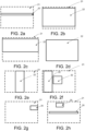
- Figure 2a shows a synchronizing image area 20 of an image frame 21 exposed by an area image sensor (not shown) according to an example.
- an image data processing device detects a predefined event, for example, a defect in the synchronizing image area 20 i.e. in a part of the exposed image
- the sensor is reconfigured to read and transfer a bigger part of at least one image frame i.e. the further analysis area 22 to the image data processing device for further analysis.
- Some possible areas 22 are also shown in figures 2b, 2c, 2d, 2e, 2f, 2g and 2h .
- the area 22 is essentially bigger than synchronizing image area 20, whereas in figure 2c the area 22 is only slightly bigger than synchronizing image area 20.
- FIG 2d the image frame 21 and the further analysis area 22 are the same size.
- the further analysis area 22 is orientated differently and in figure 2f there is two further analysis areas 22.
- Figure 2g shows a synchronizing image area 20 of an image frame 21 exposed by an area image sensor according to an example.
- Figure 2h shows an image frame 21 comprising two synchronizing image areas 20.
- the number, shape or size of synchronizing image areas 20 in one image frame 21 is not restricted, for example, there could be 1, 2, 3, 4 or even more image areas 20 i.e. separate sections in one image frame 21.
- position of synchronizing image area/s 20 in one image frame 21 is not restricted.
- the number, shape or size of further analysis area 22 is not restricted to shown examples, for example, there could be 1, 2, 3, 4 or even more further analysis areas i.e. separate sections that are transmitted to the image data processing device.
- the image data processing device may define the velocity of the object. And on the base of the defined velocity the image data processing device may, for example, in a trigger signal determine for the area image sensor the size, shape, or position of at least one bigger part of at least one image frame.
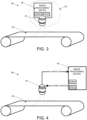
- FIG 3 shows an example, in which an operating principle of an inspection method of a machine vision system 30 is disclosed in conjunction with a moving object 33.
- the machine vision system comprises at least one smart camera 34 comprising an area image sensor 31 and an image data processing device part 32.
- the area image sensor 31 is arranged to expose image frames i.e. image matrixes from the moving object 33 and to transfer a part (i.e. synchronizing image area) of each image frame to the image data processing device part 32 of the smart camera 34.
- the image data processing device part 32 comprises at least one processor, at least one memory including computer program code for one or more program units, and means for receiving image data wirelessly or via wired connection, for example, a receiver or a transceiver and means for transferring trigger signals wirelessly or via wired connection, for example, a transmitter or a transceiver.
- processors e.g. a general purpose processor and a graphics processor and a DSP processor and/or multiple different memories e.g. volatile memory for storing data and programs at run-time and nonvolatile memory like a hard disk for permanently storing data and programs.
- the image data processing device part 32 of the smart camera 34 may be any computing device suitable for handling image data such as a computer.
- the image data processing device part 32 is in electronic communication with the area image sensor 31 via signal lines.
- the smart camera 34 may also include a video controller and an audio controller for generating signals that can be produced to the user with computer accessories.
- the smart camera 34 produces output to the user through output means.
- the video controller may be connected to a display.
- the display may be e.g. a flat panel display or a projector for producing a larger image.
- the audio controller may be connected to a sound source such as loudspeakers or earphones.
- the image data processing device part 32 is configured to receive from the area image sensor 31 a part of the image frame exposed by the area image sensor 31.
- the image data processing device part 32 analyses the above mentioned image frame part and if the image data processing device part 32 detects a predefined event, it may trigger the area image sensor 31 by indicating that a bigger part or the whole image frame must be transferred to the image data processing device part 32 for further analysis i.e. the image data processing device part 32 requests a larger part of the image frame (further analysis area) from the area image sensor 31. It is also possible that the image data processing device part 32 defines the size of the further analysis area to be transferred or the size may be predefined for the area image sensor 31.
- the image data processing device part 32 re-configures the area image sensor 31 so that the size and position of the bigger image area are dependent on conditions in the synchronizing image area, for example, so that the detected event is in the middle of the bigger image area i.e. the further analysis area.
- the number of image frames of which a bigger part is transmitted for further analysis may also be more than one.
- the camera After the area image sensor 31 has transferred the requested or predefined image data, the camera starts to transfer image frame parts until it receives the next trigger signal.
- the image data processing device part 32 may further be arranged to notify a user of the machine comprising the machine vision system 30.
- FIG 4 shows an example, in which an operating principle of an inspection method of a machine vision system 40 is disclosed in conjunction with a moving object to be monitored 43.
- the machine vision system comprises at least one area-scan camera (area image sensor) 41 and an image data processing device 42.
- the area-scan camera 41 is arranged to expose image frames i.e. image matrixes from the object to be monitored 43 and to transfer a part of each image frame to the image data processing device 42.
- the image data processing device 42 comprises at least one processor, at least one memory including computer program code for one or more program units, and means for receiving image data wirelessly or via wired connection, for example, a receiver or a transceiver and means for transferring trigger signals wirelessly or via wired connection, for example, a transmitter or a transceiver.
- processors e.g. a general purpose processor and a graphics processor and a DSP processor and/or multiple different memories e.g. volatile memory for storing data and programs at run-time and nonvolatile memory like a hard disk for permanently storing data and programs.
- the image data processing device 42 may be any computing device suitable for handling image data such as a computer.
- the image data processing device 42 is in electronic communication with the camera 41 via signal lines.
- the image data processing device 42 comprises I/O circuitry.
- the connection between the camera 41 and the image data processing device 42 is a wired or wireless network.
- the image data processing device 42 may also include a video controller and an audio controller for generating signals that can be produced to the user with computer accessories.
- the simulator produces output to the user through output means.
- the video controller may be connected to a display.
- the display may be e.g. a flat panel display or a projector for producing a larger image.
- the audio controller may be connected to a sound source such as loudspeakers or earphones.
- the image data processing device 42 is configured to receive from the camera 41 a part of the image data frame exposed by the camera 41.
- the image data processing device 42 analyses the above mentioned image area part and if the image data processing device 42 detects a predefined event, it forms a trigger signal and transmits it to the camera 41.
- the trigger signal indicates for the camera 41 that a bigger part or the whole image frame must be transferred to the image data processing device 42 for further analysis i.e. the image data processing device 42 requests a larger part of the image frame from the camera 41 by the trigger signal.
- the image data processing device 42 defines the size of the area to be transferred in the trigger signal or the size may be predefined for the camera 41.
- the image data processing device part 42 re-configures the camera 41 so that the size and position of the bigger image area are dependent on conditions in the synchronizing image area, for example so that the detected event is in the middle of the bigger image area i.e. the further analysis area.
- the number of image frames of which a bigger part is transmitted for further analysis may also be more than one.
- the camera 41 After the camera 41 has transferred the requested or predefined image data, the camera starts to transfer small image frame parts until it receives the next trigger signal.
- the image data processing device 42 is further arranged to notify a user of the machine comprising the machine vision system 40.
- Some modern cameras also offer the possibility of having multiple predetermined configuration sets, which if used can speed up the process of re-configuring the camera 41 to the different modes.
- predetermined configuration sets instead of a list of parameters, a simple command from the data processing device 42 will be enough to re-configure the camera 41.
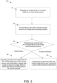
- FIG. 5 shows an example, in which a block diagram of an inspection method 50 of a machine vision system is disclosed.
- an image frame of a moving object to be monitored is exposed by an area image sensor.
- a part of the exposed image frame is transmitted to an image data processing device.
- the received part of an image frame is analysed by the image data processing device. If the received part of the image frame is detected to comprise a predefined event, in step 54, said area image sensor exposes at least one further image frame of the moving object and transmits a bigger part of said at least one further image frame to said image data processing device for further analysis. If the received part of an image frame is not detected to comprise a predefined event, in step 55, said area image sensor continues to expose at least one further image frame and to transmit a part of said at least one exposed image frame.
- a part of the image frame that is transmitted to an image data processing device may determine the size and/or position of said bigger part of the image frame, and/or the number of image frames of which a bigger part is transmitted. For example, conditions (size or placement etc.) of a predefined event in the part of the image frame may determine the size and/or position of said bigger part of the image frame, and/or the number of image frames of which a bigger part is transmitted.
- the image sensor is configured to transfer a bigger part of the first image frame after the detected event, whereas in some examples, the image sensor is configured to transfer a bigger part of the image frame after, for example, a predetermined number of image frames from the detected event.
- an apparatus that is a computing device, for example, an image data processing device may comprise circuitry and electronics for analysing, receiving and transmitting data, a computer program code in a memory, and a processor which, when running the computer program code, causes the apparatus to carry out the features of an example.
- the processor when running the computer program code may carry out all the steps of the following method: exposing an image frame of an object to be monitored by an area image sensor, transmitting a part of said exposed image frame, analysing the received part of said image frame, and if said received part of said image frame is detected to comprise at least one predefined event, said image data processing device is arranged to transmit a trigger signal to said area image sensor, and wherein said area image sensor is arranged to transmit a bigger part of said image frame to said image data processing device for further analysis, or if said received part of said image frame is not detected to comprise a predefined event, said area image sensor continues to expose at least one further image frame and to transmit a part of said at least one further image frame.
Landscapes
- Engineering & Computer Science (AREA)
- Physics & Mathematics (AREA)
- General Physics & Mathematics (AREA)
- Health & Medical Sciences (AREA)
- Life Sciences & Earth Sciences (AREA)
- Chemical & Material Sciences (AREA)
- General Health & Medical Sciences (AREA)
- Immunology (AREA)
- Analytical Chemistry (AREA)
- Biochemistry (AREA)
- Pathology (AREA)
- Computer Vision & Pattern Recognition (AREA)
- Signal Processing (AREA)
- Theoretical Computer Science (AREA)
- Multimedia (AREA)
- Textile Engineering (AREA)
- Quality & Reliability (AREA)
- Food Science & Technology (AREA)
- Medicinal Chemistry (AREA)
- Biomedical Technology (AREA)
- Investigating Materials By The Use Of Optical Means Adapted For Particular Applications (AREA)
- Studio Devices (AREA)
- Image Analysis (AREA)
- General Factory Administration (AREA)
- Image Processing (AREA)
- Closed-Circuit Television Systems (AREA)
Description
- The present invention relates to a method for imaging of continuous manufacturing processes, in which method an area-scan camera is used for imaging of an object to be monitored.
- The invention also relates to a system and a computer program product causing an apparatus to carry out the method.
- In continuous manufacturing processes, there are materials or products constantly running through the machine. In such processes, for example, in paper machines, the product must be monitored in order to detect possible deviations, and to obtain a final product of high quality, for example, by machine vision systems such as camera systems comprising a plurality of area-scan (array) cameras. With an area-scan camera, a matrix of pixels provides an image of the monitored target. As the monitored target moves past the area-scan camera system, images of it are exposed by an area image sensor of the camera and transferred to a processing unit for analysis.
- The monitored process may contain events that need to be captured completely within a single image. The capturing of these events is often triggered by an external trigger signal received, for example, from a photoelectric cell, automatic logic, or a pulse sensor.
-
US 2008/0001104 discloses a method of detecting unwanted objects or faults in containers containing a fluid or liquid, wherein at least partly transparent or translucent containers are imaged by a first camera. These containers are also imaged by a second camera in order to confirm the result of said first processing. - Stephan Hengstler et al: "MeshEye: A Hybrid-Resolution Smart Camera Mote for Applications in Distributed Intelligent Surveillance", INFORMATION PROCESSING IN SENSOR NETWORKS, 2007. IPSN 2007. 6TH INTERN ATIONAL SYMPOSIUM ON, IEEE, PI, 1 April2007 (2007-04-01) discloses a low-power ARM7-based smart camera mote architecture. It is designed for real-time object detection and in-node processing for applications in distributed intelligent surveillance. Its hybrid-resolution vision system deploys two kilopixel imagers to trigger region of interest acquisition through a high-resolution camera module. The underlying image processing algorithms for object detection, tracking, and acquisition were discussed and illustrated on an outdoor scene.
- WILLIAM ROBERT HAAS ET AL: "Automatic image capture method for a digital camera", RESEARCH OISCLOSURE, KENNETH MASON PUBLICATIONS, HAMPSHIRE, UK, GB, vol. 497, no. 81, 1 September 2005 (2005-09-01 ), XP007135476, ISSN: 037 4-4353 discloses a method of triggering a digital camera to capture an image by means of teaching it what the image should look like. A user performs the following steps: 1. creates a scene similar to the one that the camera should trigger on, 2. sets the camera to "teach trigger image" mode, frame the scene, and press the shutter, 3. optionally selects a specific region of the captured image from step 2 to use for comparison, and 4. sets the camera to "auto trigger" mode, frame the scene, and presses the shutter button. When the camera detects a scene similar to the image captured in step 2 it will automatically capture one or more pictures.
- The present invention relates to a method for a computing device, for example, an image data processing device of a machine vision system. An area image sensor of the machine vision system exposes an image frame of an object to be monitored without external triggering. A part of the image frame may be transferred to the image data processing device for analysing. When the image data processing device detects a predefined event in that part of the image frame, the configuration of the machine vision system is changed so that a bigger part of at least one further image frame is transferred from the area image sensor to a memory of the image data processing device for further analysis. The scope of protection sought for various embodiments of the invention is set out by the independent claims. The embodiments, examples and features, if any, described in this specification that do not fall under the scope of the independent claims are to be interpreted as examples useful for understanding various embodiments of the invention.
- Various aspects of the invention include a method for a computing device of a machine vision system, a machine vision system and a computer program product comprising instructions to perform the method.
- According to a first aspect, there is provided a method for exposing an image frame of an object to be monitored by an area image sensor, transmitting an image part of said image frame to an image data processing device, and analysing the image part by said image data processing device, and if said received part of said image frame is detected to comprise at least one predefined event, said image data processing device is arranged to transmit a trigger signal for triggering said area image sensor so that said area image sensor is reconfigured to expose a further image frame and to transmit an image part of said further image frame to said image data processing device for further analysis, wherein the image part of said further image frame is bigger than the image part of said image frame, otherwise if said image part is not detected to comprise a predefined event, said area image sensor continues to expose an image frame of the object to be monitored and to transmit an image part to the image data processing device.
- According to an example, said image part comprises multiple separate sections of said image frame. According to an example, said image part comprises multiple separate sections of said image frame. According to an example, said image part of said further image frame comprise multiple separate sections or is the whole further image frame. According to an example, said image part comprising at least one predefined event determines the size and position of said image part of said further image, or a number of further image frames. According to an example, said area image sensor is exposing image frames and transmitting image parts without an external trigger signal.
- According to a second aspect, there is provided a machine vision system for an object to be monitored comprising an area image sensor and an image data processing device, wherein said area image sensor is arranged to expose an image frame of said object to be monitored and to transmit an image part of the image frame to said image data processing device for analysing; and wherein said image data processing device is arranged to transmit a trigger signal for triggering said area image sensor so that said area image sensor is reconfigured to expose a further image frame and to transmit an image part of said further image frame to said image data processing device for further analysis, which image part of said further image frame is bigger than the image area part of said image frame, if the received part of said image frame is detected to comprise at least one predefined event, otherwise said area image sensor continues back to expose an image frame of the object to be monitored and to transmit an image part of said image frame to the image data processing device.
- According to an example, said area image sensor and an image data processing device are part of a smart camera. According to an example, said image part of said image frame comprises multiple separate sections. According to an example, said image part of the further image frame comprises multiple separate sections of said image frame or is the whole further image frame. According to an example, said image part of the image frame comprising at least one predefined event determines the size and position of said further image frame, or the number of further image frames. According to an example, said area image sensor is arranged to expose an image frame of the object to be monitored and to transmit an image part of said image frame to said image data processing device after said image part of said further image frame is transmitted to said image data processing device for further analysis. According to an example, said area image sensor is configured to expose image frames and transmit parts of image frames without an external trigger signal.
- According to a third aspect, there is provided a computer program product, stored on a computer readable medium and executable in a computing device, wherein the computer program product comprises instructions to expose an image frame of an object to be monitored by an area image sensor, transmit an image part of said image frame to an image data processing device, analyse the image part by said image data processing device, and further if said image part of said image frame is detected to comprise at least one predefined event, said image data processing device is instructed to transmit a trigger signal for triggering said area image sensor so that said area image sensor is reconfigured to expose a further image frame and transmit an image bigger part of said further image frame to said image data processing device for further analysis, which image part of said further image frame is bigger than the image part of said image frame, or if said image part of said image frame is not detected to comprise a predefined event, said area image sensor is instructed to continue expose at least one further image frame of the object to be monitored and to transmit an image part of said image frame to the image data processing device.
- According to an example, said image part of the image frame comprises multiple separate sections of said image frame. According to an example, said image part of the further image frame comprises multiple separate sections of said image frame or is the whole image frame. According to an example, said image part of said image frame comprising at least one predefined event determines the size and position of said further image frame, or a number of further image frames. According to an example, the computer program product further comprises instructions to expose an image frame of the object to be monitored and to transmit an image part of said image frame to said image data processing device after said image part of said further image frame is transmitted to said image data processing device for further analysis. According to an example, said area image sensor is instructed to expose image frames and transmit image parts of said image frames without an external trigger signal.
- In the following, the invention will be described in more detail with reference to the appended drawings, in which
- Figs. 1a-c
- show inspection states of a machine vision system according to an example,
- Figs. 2a-h
- show sizes of inspection image areas of a machine vision system according to an example,
- Fig. 3
- shows an example, in which an operating principle of inspection method of a machine vision system is disclosed,
- Fig. 4
- shows an example, in which an operating principle of inspection method of a machine vision system is disclosed, and
- Fig. 5
- shows an example, in which a block diagram of an inspection method of a machine vision system is disclosed.
- Usually, an area image sensor of a machine vision system inspects a moving object and exposes images one image frame, i.e. image matrix at a time as the object being monitored moves past the field of view of the area image sensor. Exposed images are captured images. The object to be monitored may be, for example, the web-like material of a paper or cardboard machine, or some other kind of machine comprising moving parts to be monitored, such as a printing machine comprising a moving roll, or an assembly machine.
- Each exposed image is transferred to a processing unit for analysis. The image transferring process from the sensor to the processing unit is time consuming, and thus the larger the size of the images being transferred, the lower the frame frequency of the camera system must be. Because of the limited frame frequency, events that need to be captured completely within a single image may instead end up being captured only partly, for example so that part of the event is in one image and the rest is in the following image. Therefore, machine vision systems are often externally triggered by an external trigger signal received, for example, from a photoelectric cell, automatic logic or pulse sensor, for giving an indication of when images should be exposed so that the whole event is captured within a single image.
- However, it is also possible to use area image sensors i.e. image matrix sensors in machine vision systems for the aforementioned usage without external triggering if only a part of the image frame i.e. image matrix is read and transferred to an image data processing device such as to a logic circuit, digital signal processor (DSP) or an image data computer. This read and transferred part of the image frame may be called, for example, a synchronizing image area. When the image data processing device detects a predefined event, such as a definite change, object, or pattern, in the synchronizing image area, the configuration of the image sensor is changed so that the whole image frame, or at least a bigger part of the image frame than the synchronizing image area, is read and transferred from the camera to a memory of the image data processing device for further analysis and/or measuring. The predefined event may be, for example, a hole that is made on purpose to the moving object and/or a deviation such as a definite change, pattern and/or unwanted hole in the object or any other event that is suitable to be monitored by used camera. The predefined event is defined for the image data processing device in advance. Thus, the detected event acts as a trigger for the machine vision system that causes the transmission of the whole, or at least a bigger part of at least one image frame to the image data processing device and for further analysis of the image in the image data processing device. It is also possible, that the size and position of the bigger part of the image frame are dependent on conditions in the synchronizing image area, for example so that the bigger part is aligned to contain the detected event in the middle of the transmitted image area. It is also possible, that the image sensor is not configured to transfer a bigger part of the first image frame after the detected event, but is instead configured to transfer a bigger part of the image frame after, for example, a predetermined number of image frames from the detected event. After transmitting the bigger part of at least one frame, the machine vision system is reconfigured and it resumes reading and transferring only synchronizing image areas until a new predefined event is detected.
- In other words, an area image sensor captures images i.e. image frames of a moving object. For capturing an image of the object the image frame area is exposed and exposed image frame area is then captured. In fact capturing includes exposing. After capturing of the image frame area, the area image sensor transmits a part of that image frame to an image data processing device. This transmitted part is so called synchronizing image area part. The image data processing device analyses the synchronizing image area part for detecting a predefined event(s). If the image data processing device detect a predefined event(s) it is arranged to transmit a trigger signal for triggering the area image sensor. On the basis of this trigger signal the area image sensor is reconfigured i.e. configuration of the area image sensor is changed. The area image sensor captures a new image frame essentially from the same area of the object as the image frame comprising the synchronizing image area part comprising the detected predefined event(s).
- However, due to reconfiguration, the area image sensor reads a part of the new image frame. This part may be called as a further analysis area part. However, it is also possible that the area image sensor reads more than one parts of the new image frame. In many cases the further analysis area part is bigger than the synchronizing image area part, for example, so that whole predefined event can be seen from the new part if the predefined event was only partly shown in synchronizing image area part. It is also possible that the further analysis area part is smaller or the same size than the synchronizing image area part. The further analysis area part may also have different shape. After reading the further analysis area part, the area image sensor transmits this further analysis area part to the image data processing device for further analysis. After this transmission the area image sensor is again reconfigured and it returns to image and transmit synchronizing image area part(s). However, if the area image sensor does not found any predefined event(s), the area image sensor continues to image and transmit synchronizing image area part(s) to the image data processing device that analyses those parts to find predefined event(s).
- A synchronizing image part of the image frame and a further analysis area part of the image frame may comprise multiple separate sections of said image frame i.e. it may consist of several parts. The further analysis area part may also be the whole image frame.
- The further analysis area part's size and position relative to the image frame may be determined on the basis of the synchronizing image part comprising at least one predefined event. The synchronizing image part comprising at least one predefined event may also determine a number of image frames that are taken for further analysis.
- The area image sensor may capture and transmit synchronizing image parts without an external trigger signal, because the size of the synchronizing image part is predetermined small enough.
-
Figures 1a, 1b and 1c show inspection states of a machine vision system according to an example. Anarea image sensor 10 is arranged to expose images from an object to be monitored 11. In this example the object to be monitored 11 is movable web-like material.Figure 1a shows a first state, a so-called normal state of the machine vision system, where thearea image sensor 10 exposes and transfers a synchronizing image area to a memory of an image data processing device (not shown). This synchronizingimage area 12 is a part of theimage frame 13 i.e.image matrix 13 exposed by thesensor 10 from the object to be monitored 11. The image data processing device is configured to detectevents 14 from the synchronizingimage area 12.Events 14 to be detected are defined for the processing device in advance. In this example, theevent 14 to be detected is a deviation on the moving object to be monitored 11, for example, a hole. If the image data processing device detects at least oneevent 14 in the synchronizingimage area 12, the machine vision system changes to a second state shown infigure 1b , where thesensor 10 is re-configured by the image data processing device so that thesensor 10 of the machine vision system reads and transfers abigger part 15 of at least oneimage frame 13 to the memory of the image data processing device for more detailed analysis. Thebigger part 15 of theimage frame 13 is so-called further analysis area. In this example, thebigger part 15 is same as theimage frame 13. After transferring thebigger part 15 of at least oneimage frame 13, the machine vision system resets to the first state and thesensor 10 continues to expose images from the movingobject 11 and to read and transfer synchronizingimage areas 12 to the image data processing device. If a new event is detected, the image system switches again to the second state. -
Figure 2a shows a synchronizingimage area 20 of animage frame 21 exposed by an area image sensor (not shown) according to an example. When an image data processing device (not shown) detects a predefined event, for example, a defect in the synchronizingimage area 20 i.e. in a part of the exposed image, the sensor is reconfigured to read and transfer a bigger part of at least one image frame i.e. thefurther analysis area 22 to the image data processing device for further analysis. Somepossible areas 22 are also shown infigures 2b, 2c, 2d, 2e, 2f, 2g and 2h . Infigure 2b , thearea 22 is essentially bigger than synchronizingimage area 20, whereas infigure 2c thearea 22 is only slightly bigger than synchronizingimage area 20. Infigure 2d theimage frame 21 and thefurther analysis area 22 are the same size. Infigure 2e thefurther analysis area 22 is orientated differently and infigure 2f there is twofurther analysis areas 22.Figure 2g shows a synchronizingimage area 20 of animage frame 21 exposed by an area image sensor according to an example.Figure 2h shows animage frame 21 comprising two synchronizingimage areas 20. The number, shape or size of synchronizingimage areas 20 in oneimage frame 21 is not restricted, for example, there could be 1, 2, 3, 4 or evenmore image areas 20 i.e. separate sections in oneimage frame 21. In addition, position of synchronizing image area/s 20 in oneimage frame 21 is not restricted. Further, the number, shape or size offurther analysis area 22 is not restricted to shown examples, for example, there could be 1, 2, 3, 4 or even more further analysis areas i.e. separate sections that are transmitted to the image data processing device. - In addition, when two or more parts of the exposed image are transmitted to an image data processing device, the image data processing device may define the velocity of the object. And on the base of the defined velocity the image data processing device may, for example, in a trigger signal determine for the area image sensor the size, shape, or position of at least one bigger part of at least one image frame.
-
Figure 3 shows an example, in which an operating principle of an inspection method of amachine vision system 30 is disclosed in conjunction with a movingobject 33. The machine vision system comprises at least onesmart camera 34 comprising anarea image sensor 31 and an image dataprocessing device part 32. Thearea image sensor 31 is arranged to expose image frames i.e. image matrixes from the movingobject 33 and to transfer a part (i.e. synchronizing image area) of each image frame to the image dataprocessing device part 32 of thesmart camera 34. - The image data
processing device part 32 comprises at least one processor, at least one memory including computer program code for one or more program units, and means for receiving image data wirelessly or via wired connection, for example, a receiver or a transceiver and means for transferring trigger signals wirelessly or via wired connection, for example, a transmitter or a transceiver. There may be multiple processors e.g. a general purpose processor and a graphics processor and a DSP processor and/or multiple different memories e.g. volatile memory for storing data and programs at run-time and nonvolatile memory like a hard disk for permanently storing data and programs. The image dataprocessing device part 32 of thesmart camera 34 may be any computing device suitable for handling image data such as a computer. The image dataprocessing device part 32 is in electronic communication with thearea image sensor 31 via signal lines. Thesmart camera 34 may also include a video controller and an audio controller for generating signals that can be produced to the user with computer accessories. Thesmart camera 34 produces output to the user through output means. The video controller may be connected to a display. The display may be e.g. a flat panel display or a projector for producing a larger image. The audio controller may be connected to a sound source such as loudspeakers or earphones. - The image data
processing device part 32 is configured to receive from the area image sensor 31 a part of the image frame exposed by thearea image sensor 31. The image dataprocessing device part 32 analyses the above mentioned image frame part and if the image dataprocessing device part 32 detects a predefined event, it may trigger thearea image sensor 31 by indicating that a bigger part or the whole image frame must be transferred to the image dataprocessing device part 32 for further analysis i.e. the image dataprocessing device part 32 requests a larger part of the image frame (further analysis area) from thearea image sensor 31. It is also possible that the image dataprocessing device part 32 defines the size of the further analysis area to be transferred or the size may be predefined for thearea image sensor 31. In addition, it is possible that the image dataprocessing device part 32 re-configures thearea image sensor 31 so that the size and position of the bigger image area are dependent on conditions in the synchronizing image area, for example, so that the detected event is in the middle of the bigger image area i.e. the further analysis area. The number of image frames of which a bigger part is transmitted for further analysis may also be more than one. After thearea image sensor 31 has transferred the requested or predefined image data, the camera starts to transfer image frame parts until it receives the next trigger signal. The image dataprocessing device part 32 may further be arranged to notify a user of the machine comprising themachine vision system 30. -
Figure 4 shows an example, in which an operating principle of an inspection method of amachine vision system 40 is disclosed in conjunction with a moving object to be monitored 43. The machine vision system comprises at least one area-scan camera (area image sensor) 41 and an imagedata processing device 42. The area-scan camera 41 is arranged to expose image frames i.e. image matrixes from the object to be monitored 43 and to transfer a part of each image frame to the imagedata processing device 42. - The image
data processing device 42 comprises at least one processor, at least one memory including computer program code for one or more program units, and means for receiving image data wirelessly or via wired connection, for example, a receiver or a transceiver and means for transferring trigger signals wirelessly or via wired connection, for example, a transmitter or a transceiver. There may be multiple processors e.g. a general purpose processor and a graphics processor and a DSP processor and/or multiple different memories e.g. volatile memory for storing data and programs at run-time and nonvolatile memory like a hard disk for permanently storing data and programs. The imagedata processing device 42 may be any computing device suitable for handling image data such as a computer. The imagedata processing device 42 is in electronic communication with thecamera 41 via signal lines. For handling the signals to/from the signal lines, the imagedata processing device 42 comprises I/O circuitry. The connection between thecamera 41 and the imagedata processing device 42 is a wired or wireless network. The imagedata processing device 42 may also include a video controller and an audio controller for generating signals that can be produced to the user with computer accessories. The simulator produces output to the user through output means. The video controller may be connected to a display. The display may be e.g. a flat panel display or a projector for producing a larger image. The audio controller may be connected to a sound source such as loudspeakers or earphones. - The image
data processing device 42 is configured to receive from the camera 41 a part of the image data frame exposed by thecamera 41. The imagedata processing device 42 analyses the above mentioned image area part and if the imagedata processing device 42 detects a predefined event, it forms a trigger signal and transmits it to thecamera 41. The trigger signal indicates for thecamera 41 that a bigger part or the whole image frame must be transferred to the imagedata processing device 42 for further analysis i.e. the imagedata processing device 42 requests a larger part of the image frame from thecamera 41 by the trigger signal. It is also possible that the imagedata processing device 42 defines the size of the area to be transferred in the trigger signal or the size may be predefined for thecamera 41. In addition, it is possible that the image dataprocessing device part 42 re-configures thecamera 41 so that the size and position of the bigger image area are dependent on conditions in the synchronizing image area, for example so that the detected event is in the middle of the bigger image area i.e. the further analysis area. The number of image frames of which a bigger part is transmitted for further analysis may also be more than one. After thecamera 41 has transferred the requested or predefined image data, the camera starts to transfer small image frame parts until it receives the next trigger signal. The imagedata processing device 42 is further arranged to notify a user of the machine comprising themachine vision system 40. - Some modern cameras also offer the possibility of having multiple predetermined configuration sets, which if used can speed up the process of re-configuring the
camera 41 to the different modes. In the case of predetermined configuration sets, instead of a list of parameters, a simple command from thedata processing device 42 will be enough to re-configure thecamera 41. -
Figure 5 shows an example, in which a block diagram of aninspection method 50 of a machine vision system is disclosed. Instep 51 an image frame of a moving object to be monitored is exposed by an area image sensor. In step 52 a part of the exposed image frame is transmitted to an image data processing device. Instep 53 the received part of an image frame is analysed by the image data processing device. If the received part of the image frame is detected to comprise a predefined event, instep 54, said area image sensor exposes at least one further image frame of the moving object and transmits a bigger part of said at least one further image frame to said image data processing device for further analysis. If the received part of an image frame is not detected to comprise a predefined event, instep 55, said area image sensor continues to expose at least one further image frame and to transmit a part of said at least one exposed image frame. - In some example, a part of the image frame that is transmitted to an image data processing device may determine the size and/or position of said bigger part of the image frame, and/or the number of image frames of which a bigger part is transmitted. For example, conditions (size or placement etc.) of a predefined event in the part of the image frame may determine the size and/or position of said bigger part of the image frame, and/or the number of image frames of which a bigger part is transmitted.
- In some examples, the image sensor is configured to transfer a bigger part of the first image frame after the detected event, whereas in some examples, the image sensor is configured to transfer a bigger part of the image frame after, for example, a predetermined number of image frames from the detected event.
- The various examples can be implemented with the help of computer program code that resides in a memory and causes an apparatus to carry out the invention. For example, the apparatus that is a computing device, for example, an image data processing device may comprise circuitry and electronics for analysing, receiving and transmitting data, a computer program code in a memory, and a processor which, when running the computer program code, causes the apparatus to carry out the features of an example. The processor, when running the computer program code may carry out all the steps of the following method: exposing an image frame of an object to be monitored by an area image sensor, transmitting a part of said exposed image frame, analysing the received part of said image frame, and if said received part of said image frame is detected to comprise at least one predefined event, said image data processing device is arranged to transmit a trigger signal to said area image sensor, and wherein said area image sensor is arranged to transmit a bigger part of said image frame to said image data processing device for further analysis, or if said received part of said image frame is not detected to comprise a predefined event, said area image sensor continues to expose at least one further image frame and to transmit a part of said at least one further image frame.
- Considerable advantages are achieved by the present invention when compared to methods and systems of existing machine vision systems comprising at least one area-scan camera. By means of the arrangement according to the invention it is possible to use area-scan cameras without a need of an external trigger signal. In addition, by means of the arrangement according to the invention it is also possible to utilize the data of the whole image frame whenever needed. The present invention is not limited to the above-presented examples, but it can be modified within the scope of the appended claims.
- It is obvious that the present invention is not limited solely to the above-presented examples, but it can be modified within the scope of the appended claims.
Claims (11)
- A one camera monitoring method, comprising:exposing an image frame (13) of an object to be monitored (11) by an area image sensor (10, 31, 41);transmitting an image part (12) of said image frame (13) to an image data processing device;analysing said image part (12) by said image data processing device (32, 42), characterised in that;- if said image part (12) is detected to comprise at least one predefined event (14) of at least two different predefined events (14), said image data processing device (32, 42) is arranged to transmit a trigger signal for triggering said area image sensor (10, 31, 41) so that said area image sensor (10, 31, 41) is reconfigured to expose a further image frame and to transmit an image part (15) of said further image frame to said image data processing device (32, 42) for further analysis, wherein the image part (15) of said further image frame is bigger than the image part (12) of said image frame (13), and wherein each of said at least two predefined events (14) is configured to determine a particular size and position for the image part (15) of said further image frame, and- if said image part (12) is not detected to comprise a predefined event (14) of said at least two different predefined events (14), said area image sensor (10, 31, 41) continues back to expose an image frame (13) of the object to be monitored (11) and to transmit an image part (12) of said image frame to the image data processing device (32, 42).
- The method according to claim 1, characterized in that said image part (12) comprises multiple separate sections.
- The method according to claim 1 or 2, characterized in that said image part (15) of said further image frame comprise multiple separate sections or is the whole further image frame.
- The method according to any of the claims 1 to 3, characterized in that said area image sensor (10, 31, 41) is exposing image frames (13) and transmitting image parts (12) of image frames (13) without an external trigger signal.
- A one camera machine vision system for an object to be monitored (11) comprising an area image sensor (10, 31, 41) and an image data processing device (32, 42), wherein said area image sensor (10, 31, 41) is arranged to expose an image frame (13) of said object to be monitored (11) and to transmit an image part (12) of the image frame (13) to said image data processing device (32, 42) for analysing;
characterised in that- if said image part (12) is detected to comprise at least one predefined event (14) of at least two different predefined events (14), said image data processing device (32, 42) is arranged to transmit a trigger signal for triggering said area image sensor (10, 31, 41) so that said area image sensor (10, 31, 41) is reconfigured to expose a further image frame and to transmit an image part (15) of said further image frame to said image data processing device (32, 42) for further analysis, wherein the image part (15) of said further image frame is bigger than the image area part (12) of said image frame (13), and wherein each of said at least two predefined events (14) is configured to determine a particular size and position for the image part (15) of said further image frame, and- if said image part (12) of said image frame (13) is not detected to comprise a predefined event (14) of said at least two different predefined events (14), said area image sensor (10, 31, 41) continues back to expose an image frame of the object to be monitored (11) and to transmit an image part (12) of said image frame (13) to the image data processing device (32, 42). - The machine vision system according to claim 5, characterized in that said image part (12) of said image frame (13) comprise multiple separate sections.
- The machine vision system according to claim 5 or 6, characterized in that said image part (15) of said further image frame comprise multiple separate sections or is the whole further image frame.
- The machine vision system according to any of the claims 5 to 7, characterized in that the said area image sensor (10, 31, 41) is arranged to expose an image frame (13) of the object to be monitored (11) and to transmit an image part (12) of said image frame (13) to said image data processing device (32, 42) after said image part (15) of said further image frame is transmitted to said image data processing device (32, 42) for further analysis.
- A computer program product of one camera machine vision system, stored on a computer readable medium and being executable in a computing device, wherein the computer program product comprises instructions to:expose an image frame (13) of an object to be monitored (11) by an area image sensor (10, 31, 41);transmit an image part (12) of said image frame (13) to an image data processing device (32, 42);analyse said image part (12) by said image data processing device (32, 42), characterised in that;- if said image part (12) of said image frame (13) is detected to comprise at least one predefined event (14) of at least two different predefined events (14), said image data processing device (32, 42) is instructed to transmit a trigger signal for triggering said area image sensor (10, 31, 41) so that said area image sensor (10, 31, 41) is reconfigured to expose a further image frame and to transmit an image part (15) of said further image frame to said image data processing device (32, 42) for further analysis, wherein the image part (15) of said further image frame is bigger than the image part (12) of said image frame (13), and wherein each of said at least two predefined events (14) is configured to determine a particular size and position for the image part (15) of said further image frame, and- if said image part (12) of said image frame (13) is not detected to comprise a predefined event (14) of said at least two different predefined events (14), said area image sensor (10, 31, 41) is instructed to expose an image frame (13) of the object to be monitored (11) and to transmit an image part (12) of said image frame (13) of the object to be monitored (11) to the image data processing device (32, 42).
- The computer program product according to claim 9, characterized in that said image part (15) of said further image frame comprise multiple separate sections or that said image part (15) of said further image frame of said at least one predefined event (14) is the whole image frame.
- The computer program product according to claims 9 or 10, characterized in that the computer program product further comprises instructions to;
expose an image frame (13) of the object to be monitored (11) and transmit an image part (12) of said image frame (13) to said image data processing device (32, 42) after said image part (15) of said further image frame is transmitted to said image data processing device (32, 42) for further analysis.
Applications Claiming Priority (2)
| Application Number | Priority Date | Filing Date | Title |
|---|---|---|---|
| FI20135749A FI128403B (en) | 2013-07-05 | 2013-07-05 | Synchronize shooting |
| PCT/FI2014/050564 WO2015001196A1 (en) | 2013-07-05 | 2014-07-07 | Synchronization of imaging |
Publications (4)
| Publication Number | Publication Date |
|---|---|
| EP3017425A1 EP3017425A1 (en) | 2016-05-11 |
| EP3017425A4 EP3017425A4 (en) | 2018-08-15 |
| EP3017425B1 true EP3017425B1 (en) | 2024-03-20 |
| EP3017425C0 EP3017425C0 (en) | 2024-03-20 |
Family
ID=52143169
Family Applications (1)
| Application Number | Title | Priority Date | Filing Date |
|---|---|---|---|
| EP14819582.9A Active EP3017425B1 (en) | 2013-07-05 | 2014-07-07 | Synchronization of imaging |
Country Status (7)
| Country | Link |
|---|---|
| US (1) | US9532015B2 (en) |
| EP (1) | EP3017425B1 (en) |
| JP (1) | JP2016532099A (en) |
| KR (1) | KR102038181B1 (en) |
| CN (1) | CN105917379B (en) |
| FI (1) | FI128403B (en) |
| WO (1) | WO2015001196A1 (en) |
Families Citing this family (7)
| Publication number | Priority date | Publication date | Assignee | Title |
|---|---|---|---|---|
| US20160364525A1 (en) * | 2015-06-09 | 2016-12-15 | Toshiba Medical Systems Corporation | Medical image processing apparatus and medical image transfer system |
| FI20155643A (en) | 2015-09-08 | 2017-03-09 | Procemex Oy Ltd | Optical detection of fluorescent liquid from a wood fiber web |
| FI128850B (en) | 2016-05-06 | 2021-01-29 | Procemex Oy Ltd | Procedure for computer vision and systems for monitoring manufacturing processes |
| FI128735B (en) * | 2016-05-06 | 2020-11-13 | Procemex Oy Ltd | A machine vision method and system |
| US11920299B2 (en) | 2020-03-06 | 2024-03-05 | Ibs Of America | Formation detection system and a process of controlling |
| FI129971B (en) | 2020-06-24 | 2022-11-30 | Procemex Oy Ltd | Smart synchronization method of a web inspection system |
| CN113445201B (en) * | 2021-07-20 | 2022-09-27 | 大易智慧信息科技(苏州)有限公司 | Double needle bar warp knitting machine broken yarn on-line detection system based on camera array and method thereof |
Family Cites Families (30)
| Publication number | Priority date | Publication date | Assignee | Title |
|---|---|---|---|---|
| JPH05240805A (en) * | 1992-02-27 | 1993-09-21 | Kawasaki Steel Corp | Surface defect inspection device |
| JPH1065940A (en) * | 1996-06-13 | 1998-03-06 | Olympus Optical Co Ltd | Image pickup device |
| JP3015325B2 (en) * | 1996-06-26 | 2000-03-06 | 東芝エンジニアリング株式会社 | Streak inspection method and device |
| JPH1194760A (en) * | 1997-09-24 | 1999-04-09 | Olympus Optical Co Ltd | Microscope for detecting defect |
| US5935285A (en) * | 1997-12-30 | 1999-08-10 | Coors Brewing Company | Method for inspecting manufactured articles |
| US6947587B1 (en) * | 1998-04-21 | 2005-09-20 | Hitachi, Ltd. | Defect inspection method and apparatus |
| EP0979995A1 (en) | 1998-08-12 | 2000-02-16 | Hildeco OY Ltd. | Method and system for monitoring a paper web, a paper pulp or a wire travelling in a paper machine |
| FI990159L (en) * | 1999-01-28 | 2000-07-29 | Valmet Automation Inc | Method for controlling the quality of a non-woven web |
| FI114741B (en) * | 2001-05-11 | 2004-12-15 | Metso Automation Oy | Procedure for checking quality and condition on the basis of thermography |
| DE10260464A1 (en) * | 2002-12-21 | 2004-07-01 | Voith Paper Patent Gmbh | Method and device for operating a machine for producing and / or finishing a material web |
| US7027934B2 (en) * | 2003-09-24 | 2006-04-11 | 3M Innovative Properties Company | Apparatus and method for automated web inspection |
| US20050117017A1 (en) | 2003-12-01 | 2005-06-02 | Baer Richard L. | System and method for imaging regions of interest |
| JP2005308464A (en) * | 2004-04-20 | 2005-11-04 | Dainippon Screen Mfg Co Ltd | Flaw detector and flaw detecting method |
| EP1630550A1 (en) * | 2004-08-27 | 2006-03-01 | Moller & Devicon A/S | Methods and apparatuses of detecting foreign particles or faults in a plurality of filled containers |
| WO2006067547A1 (en) * | 2004-12-23 | 2006-06-29 | Nokia Corporation | Method for extracting of multiple sub-windows of a scanning area by means of a digital video camera |
| CN101208042B (en) * | 2005-06-28 | 2010-11-17 | 柯尼卡美能达医疗印刷器材株式会社 | Abnormal shadow candidate detection method and abnormal shadow candidate detection device |
| JP2007049673A (en) * | 2005-07-13 | 2007-02-22 | Ricoh Co Ltd | Image reading apparatus, image forming apparatus, image inspection apparatus, and image forming system |
| JP2007240432A (en) * | 2006-03-10 | 2007-09-20 | Omron Corp | Defect inspection apparatus and defect inspection method |
| US8014586B2 (en) * | 2007-05-24 | 2011-09-06 | Applied Vision Corporation | Apparatus and methods for container inspection |
| WO2009003702A1 (en) * | 2007-07-04 | 2009-01-08 | Thermosensorik Gmbh | Method for the automatic inspection of a welding seam using heat flow thermography |
| JP5344492B2 (en) * | 2008-07-18 | 2013-11-20 | 国立大学法人東北大学 | Structure defect imaging method, structure defect imaging device, bubble imaging method, and bubble or lesion imaging device |
| AT508159B1 (en) | 2009-06-05 | 2010-11-15 | Starlinger & Co Gmbh | ERROR DETECTION SET |
| US20110141269A1 (en) | 2009-12-16 | 2011-06-16 | Stephen Michael Varga | Systems And Methods For Monitoring On-Line Webs Using Line Scan Cameras |
| US8345949B2 (en) * | 2010-03-09 | 2013-01-01 | General Electric Company | Sequential approach for automatic defect recognition |
| FR2978831A1 (en) * | 2011-08-05 | 2013-02-08 | St Microelectronics Sa | DEFECT DETECTION THROUGH FREQUENCY IMAGING. |
| US20120293623A1 (en) * | 2011-05-17 | 2012-11-22 | Gii Acquisition, Llc Dba General Inspection, Llc | Method and system for inspecting small manufactured objects at a plurality of inspection stations and sorting the inspected objects |
| JP2013190309A (en) * | 2012-03-13 | 2013-09-26 | Toshiba Corp | Defect inspection device |
| JP5944189B2 (en) * | 2012-03-15 | 2016-07-05 | 株式会社東芝 | Mask substrate defect inspection method and defect inspection apparatus, photomask manufacturing method and semiconductor device manufacturing method |
| US9390491B2 (en) * | 2013-01-30 | 2016-07-12 | Taiwan Semiconductor Manufacturing Co., Ltd. | System and method for automatic quality control for assembly line processes |
| JP6241052B2 (en) * | 2013-03-29 | 2017-12-06 | オムロン株式会社 | Image processing system and image processing program |
-
2013
- 2013-07-05 FI FI20135749A patent/FI128403B/en active IP Right Grant
-
2014
- 2014-07-07 EP EP14819582.9A patent/EP3017425B1/en active Active
- 2014-07-07 CN CN201480038286.0A patent/CN105917379B/en active Active
- 2014-07-07 KR KR1020157036631A patent/KR102038181B1/en active Active
- 2014-07-07 JP JP2016522686A patent/JP2016532099A/en active Pending
- 2014-07-07 WO PCT/FI2014/050564 patent/WO2015001196A1/en not_active Ceased
- 2014-07-07 US US14/902,852 patent/US9532015B2/en active Active
Non-Patent Citations (1)
| Title |
|---|
| WILLIAM ROBERT HAAS ET AL: "Automatic image capture method for a digital camera", RESEARCH DISCLOSURE, KENNETH MASON PUBLICATIONS, HAMPSHIRE, UK, GB, vol. 497, no. 81, 1 September 2005 (2005-09-01), XP007135476, ISSN: 0374-4353 * |
Also Published As
| Publication number | Publication date |
|---|---|
| FI20135749L (en) | 2015-01-06 |
| CN105917379A (en) | 2016-08-31 |
| FI20135749A7 (en) | 2015-01-06 |
| CN105917379B (en) | 2019-10-11 |
| FI128403B (en) | 2020-04-30 |
| WO2015001196A1 (en) | 2015-01-08 |
| EP3017425C0 (en) | 2024-03-20 |
| KR102038181B1 (en) | 2019-10-30 |
| JP2016532099A (en) | 2016-10-13 |
| US20160142682A1 (en) | 2016-05-19 |
| US9532015B2 (en) | 2016-12-27 |
| KR20160030116A (en) | 2016-03-16 |
| EP3017425A1 (en) | 2016-05-11 |
| EP3017425A4 (en) | 2018-08-15 |
Similar Documents
| Publication | Publication Date | Title |
|---|---|---|
| US9532015B2 (en) | Synchronization of imaging | |
| EP3452806B1 (en) | A machine vision method and system | |
| EP1134718A3 (en) | Image pickup system and vehicle-mounted-type sensor system | |
| US20050137827A1 (en) | System and method for managing arrangement position and shape of device | |
| KR100989081B1 (en) | Event monitoring system and method using network camera | |
| KR101179131B1 (en) | Monitoring system using synthetic simultaneous monitoring camera with pan/tilt/zoom function | |
| EP0878965A3 (en) | Method for tracking entering object and apparatus for tracking and monitoring entering object | |
| US11032477B2 (en) | Motion stabilized image sensor, camera module and apparatus comprising same | |
| FI129971B (en) | Smart synchronization method of a web inspection system | |
| KR20190118548A (en) | Image sensor, and control system | |
| CN103548033A (en) | Image processing system and related monitoring system | |
| EP3906666A1 (en) | A method of using a machine-readable code for instructing camera for detecting and monitoring objects | |
| US20170371035A1 (en) | Protection and guidance gear or equipment with identity code and ip address | |
| KR101441755B1 (en) | A smart camera with interchangeable image senosr module and main processing module | |
| CN116033090A (en) | A multi-camera-based image acquisition control method and control device | |
| CN114040141B (en) | Data transmission method, camera, and electronic equipment | |
| CN104902224B (en) | The method and system of image data acquiring | |
| WO2004102467A3 (en) | Component fusion for face detection | |
| JP4997430B2 (en) | Captured image transmission apparatus and captured image transmission method | |
| JP4112537B2 (en) | Molding monitoring system and molding monitoring method | |
| JP2003331373A5 (en) | ||
| Faigl et al. | Camera Module for Onboard Relative Localization in SWARM of robots | |
| JP2013152565A (en) | Analyzer, control method, and program | |
| JP2008054041A (en) | Image sensor inspection device |
Legal Events
| Date | Code | Title | Description |
|---|---|---|---|
| PUAI | Public reference made under article 153(3) epc to a published international application that has entered the european phase |
Free format text: ORIGINAL CODE: 0009012 |
|
| 17P | Request for examination filed |
Effective date: 20151229 |
|
| AK | Designated contracting states |
Kind code of ref document: A1 Designated state(s): AL AT BE BG CH CY CZ DE DK EE ES FI FR GB GR HR HU IE IS IT LI LT LU LV MC MK MT NL NO PL PT RO RS SE SI SK SM TR |
|
| AX | Request for extension of the european patent |
Extension state: BA ME |
|
| DAX | Request for extension of the european patent (deleted) | ||
| A4 | Supplementary search report drawn up and despatched |
Effective date: 20180716 |
|
| RIC1 | Information provided on ipc code assigned before grant |
Ipc: H04N 1/00 20060101ALI20180710BHEP Ipc: G06T 7/00 20060101AFI20180710BHEP Ipc: G01N 21/88 20060101ALI20180710BHEP Ipc: G01N 21/89 20060101ALI20180710BHEP |
|
| STAA | Information on the status of an ep patent application or granted ep patent |
Free format text: STATUS: EXAMINATION IS IN PROGRESS |
|
| 17Q | First examination report despatched |
Effective date: 20200331 |
|
| RIC1 | Information provided on ipc code assigned before grant |
Ipc: G01N 21/88 20060101ALI20230925BHEP Ipc: G01N 21/89 20060101ALI20230925BHEP Ipc: G01N 33/34 20060101ALI20230925BHEP Ipc: D21G 9/00 20060101ALI20230925BHEP Ipc: G06T 7/00 20060101AFI20230925BHEP |
|
| GRAP | Despatch of communication of intention to grant a patent |
Free format text: ORIGINAL CODE: EPIDOSNIGR1 |
|
| STAA | Information on the status of an ep patent application or granted ep patent |
Free format text: STATUS: GRANT OF PATENT IS INTENDED |
|
| INTG | Intention to grant announced |
Effective date: 20231122 |
|
| GRAS | Grant fee paid |
Free format text: ORIGINAL CODE: EPIDOSNIGR3 |
|
| GRAA | (expected) grant |
Free format text: ORIGINAL CODE: 0009210 |
|
| STAA | Information on the status of an ep patent application or granted ep patent |
Free format text: STATUS: THE PATENT HAS BEEN GRANTED |
|
| AK | Designated contracting states |
Kind code of ref document: B1 Designated state(s): AL AT BE BG CH CY CZ DE DK EE ES FI FR GB GR HR HU IE IS IT LI LT LU LV MC MK MT NL NO PL PT RO RS SE SI SK SM TR |
|
| REG | Reference to a national code |
Ref country code: GB Ref legal event code: FG4D |
|
| REG | Reference to a national code |
Ref country code: CH Ref legal event code: EP |
|
| REG | Reference to a national code |
Ref country code: DE Ref legal event code: R096 Ref document number: 602014089739 Country of ref document: DE |
|
| REG | Reference to a national code |
Ref country code: IE Ref legal event code: FG4D |
|
| U01 | Request for unitary effect filed |
Effective date: 20240411 |
|
| U07 | Unitary effect registered |
Designated state(s): AT BE BG DE DK EE FI FR IT LT LU LV MT NL PT SE SI Effective date: 20240418 |
|
| PG25 | Lapsed in a contracting state [announced via postgrant information from national office to epo] |
Ref country code: GR Free format text: LAPSE BECAUSE OF FAILURE TO SUBMIT A TRANSLATION OF THE DESCRIPTION OR TO PAY THE FEE WITHIN THE PRESCRIBED TIME-LIMIT Effective date: 20240621 |
|
| PG25 | Lapsed in a contracting state [announced via postgrant information from national office to epo] |
Ref country code: RS Free format text: LAPSE BECAUSE OF FAILURE TO SUBMIT A TRANSLATION OF THE DESCRIPTION OR TO PAY THE FEE WITHIN THE PRESCRIBED TIME-LIMIT Effective date: 20240620 Ref country code: HR Free format text: LAPSE BECAUSE OF FAILURE TO SUBMIT A TRANSLATION OF THE DESCRIPTION OR TO PAY THE FEE WITHIN THE PRESCRIBED TIME-LIMIT Effective date: 20240320 |
|
| U20 | Renewal fee for the european patent with unitary effect paid |
Year of fee payment: 11 Effective date: 20240617 |
|
| PG25 | Lapsed in a contracting state [announced via postgrant information from national office to epo] |
Ref country code: RS Free format text: LAPSE BECAUSE OF FAILURE TO SUBMIT A TRANSLATION OF THE DESCRIPTION OR TO PAY THE FEE WITHIN THE PRESCRIBED TIME-LIMIT Effective date: 20240620 Ref country code: NO Free format text: LAPSE BECAUSE OF FAILURE TO SUBMIT A TRANSLATION OF THE DESCRIPTION OR TO PAY THE FEE WITHIN THE PRESCRIBED TIME-LIMIT Effective date: 20240620 Ref country code: HR Free format text: LAPSE BECAUSE OF FAILURE TO SUBMIT A TRANSLATION OF THE DESCRIPTION OR TO PAY THE FEE WITHIN THE PRESCRIBED TIME-LIMIT Effective date: 20240320 Ref country code: GR Free format text: LAPSE BECAUSE OF FAILURE TO SUBMIT A TRANSLATION OF THE DESCRIPTION OR TO PAY THE FEE WITHIN THE PRESCRIBED TIME-LIMIT Effective date: 20240621 |
|
| PG25 | Lapsed in a contracting state [announced via postgrant information from national office to epo] |
Ref country code: IS Free format text: LAPSE BECAUSE OF FAILURE TO SUBMIT A TRANSLATION OF THE DESCRIPTION OR TO PAY THE FEE WITHIN THE PRESCRIBED TIME-LIMIT Effective date: 20240720 |
|
| PG25 | Lapsed in a contracting state [announced via postgrant information from national office to epo] |
Ref country code: SM Free format text: LAPSE BECAUSE OF FAILURE TO SUBMIT A TRANSLATION OF THE DESCRIPTION OR TO PAY THE FEE WITHIN THE PRESCRIBED TIME-LIMIT Effective date: 20240320 |
|
| PG25 | Lapsed in a contracting state [announced via postgrant information from national office to epo] |
Ref country code: ES Free format text: LAPSE BECAUSE OF FAILURE TO SUBMIT A TRANSLATION OF THE DESCRIPTION OR TO PAY THE FEE WITHIN THE PRESCRIBED TIME-LIMIT Effective date: 20240320 |
|
| PG25 | Lapsed in a contracting state [announced via postgrant information from national office to epo] |
Ref country code: CZ Free format text: LAPSE BECAUSE OF FAILURE TO SUBMIT A TRANSLATION OF THE DESCRIPTION OR TO PAY THE FEE WITHIN THE PRESCRIBED TIME-LIMIT Effective date: 20240320 |
|
| PG25 | Lapsed in a contracting state [announced via postgrant information from national office to epo] |
Ref country code: PL Free format text: LAPSE BECAUSE OF FAILURE TO SUBMIT A TRANSLATION OF THE DESCRIPTION OR TO PAY THE FEE WITHIN THE PRESCRIBED TIME-LIMIT Effective date: 20240320 |
|
| PG25 | Lapsed in a contracting state [announced via postgrant information from national office to epo] |
Ref country code: SK Free format text: LAPSE BECAUSE OF FAILURE TO SUBMIT A TRANSLATION OF THE DESCRIPTION OR TO PAY THE FEE WITHIN THE PRESCRIBED TIME-LIMIT Effective date: 20240320 |
|
| PG25 | Lapsed in a contracting state [announced via postgrant information from national office to epo] |
Ref country code: SM Free format text: LAPSE BECAUSE OF FAILURE TO SUBMIT A TRANSLATION OF THE DESCRIPTION OR TO PAY THE FEE WITHIN THE PRESCRIBED TIME-LIMIT Effective date: 20240320 Ref country code: SK Free format text: LAPSE BECAUSE OF FAILURE TO SUBMIT A TRANSLATION OF THE DESCRIPTION OR TO PAY THE FEE WITHIN THE PRESCRIBED TIME-LIMIT Effective date: 20240320 Ref country code: RO Free format text: LAPSE BECAUSE OF FAILURE TO SUBMIT A TRANSLATION OF THE DESCRIPTION OR TO PAY THE FEE WITHIN THE PRESCRIBED TIME-LIMIT Effective date: 20240320 Ref country code: PL Free format text: LAPSE BECAUSE OF FAILURE TO SUBMIT A TRANSLATION OF THE DESCRIPTION OR TO PAY THE FEE WITHIN THE PRESCRIBED TIME-LIMIT Effective date: 20240320 Ref country code: IS Free format text: LAPSE BECAUSE OF FAILURE TO SUBMIT A TRANSLATION OF THE DESCRIPTION OR TO PAY THE FEE WITHIN THE PRESCRIBED TIME-LIMIT Effective date: 20240720 Ref country code: ES Free format text: LAPSE BECAUSE OF FAILURE TO SUBMIT A TRANSLATION OF THE DESCRIPTION OR TO PAY THE FEE WITHIN THE PRESCRIBED TIME-LIMIT Effective date: 20240320 Ref country code: CZ Free format text: LAPSE BECAUSE OF FAILURE TO SUBMIT A TRANSLATION OF THE DESCRIPTION OR TO PAY THE FEE WITHIN THE PRESCRIBED TIME-LIMIT Effective date: 20240320 |
|
| REG | Reference to a national code |
Ref country code: DE Ref legal event code: R097 Ref document number: 602014089739 Country of ref document: DE |
|
| PLBE | No opposition filed within time limit |
Free format text: ORIGINAL CODE: 0009261 |
|
| STAA | Information on the status of an ep patent application or granted ep patent |
Free format text: STATUS: NO OPPOSITION FILED WITHIN TIME LIMIT |
|
| PG25 | Lapsed in a contracting state [announced via postgrant information from national office to epo] |
Ref country code: MC Free format text: LAPSE BECAUSE OF FAILURE TO SUBMIT A TRANSLATION OF THE DESCRIPTION OR TO PAY THE FEE WITHIN THE PRESCRIBED TIME-LIMIT Effective date: 20240320 |
|
| 26N | No opposition filed |
Effective date: 20241223 |
|
| REG | Reference to a national code |
Ref country code: CH Ref legal event code: PL |
|
| GBPC | Gb: european patent ceased through non-payment of renewal fee |
Effective date: 20240707 |
|
| PG25 | Lapsed in a contracting state [announced via postgrant information from national office to epo] |
Ref country code: CH Free format text: LAPSE BECAUSE OF NON-PAYMENT OF DUE FEES Effective date: 20240731 |
|
| PG25 | Lapsed in a contracting state [announced via postgrant information from national office to epo] |
Ref country code: GB Free format text: LAPSE BECAUSE OF NON-PAYMENT OF DUE FEES Effective date: 20240707 |
|
| PG25 | Lapsed in a contracting state [announced via postgrant information from national office to epo] |
Ref country code: IE Free format text: LAPSE BECAUSE OF NON-PAYMENT OF DUE FEES Effective date: 20240707 |
|
| U20 | Renewal fee for the european patent with unitary effect paid |
Year of fee payment: 12 Effective date: 20250702 |
|
| PG25 | Lapsed in a contracting state [announced via postgrant information from national office to epo] |
Ref country code: CY Free format text: LAPSE BECAUSE OF FAILURE TO SUBMIT A TRANSLATION OF THE DESCRIPTION OR TO PAY THE FEE WITHIN THE PRESCRIBED TIME-LIMIT; INVALID AB INITIO Effective date: 20140707 |
|
| PG25 | Lapsed in a contracting state [announced via postgrant information from national office to epo] |
Ref country code: HU Free format text: LAPSE BECAUSE OF FAILURE TO SUBMIT A TRANSLATION OF THE DESCRIPTION OR TO PAY THE FEE WITHIN THE PRESCRIBED TIME-LIMIT; INVALID AB INITIO Effective date: 20140707 |