EP3017250B1 - An air-gas mixer device for premix burner equipment - Google Patents
An air-gas mixer device for premix burner equipment Download PDFInfo
- Publication number
- EP3017250B1 EP3017250B1 EP14741386.8A EP14741386A EP3017250B1 EP 3017250 B1 EP3017250 B1 EP 3017250B1 EP 14741386 A EP14741386 A EP 14741386A EP 3017250 B1 EP3017250 B1 EP 3017250B1
- Authority
- EP
- European Patent Office
- Prior art keywords
- valve unit
- conduit
- seat
- fan
- cover plate
- Prior art date
- Legal status (The legal status is an assumption and is not a legal conclusion. Google has not performed a legal analysis and makes no representation as to the accuracy of the status listed.)
- Not-in-force
Links
Images




Classifications
-
- F—MECHANICAL ENGINEERING; LIGHTING; HEATING; WEAPONS; BLASTING
- F23—COMBUSTION APPARATUS; COMBUSTION PROCESSES
- F23D—BURNERS
- F23D14/00—Burners for combustion of a gas, e.g. of a gas stored under pressure as a liquid
- F23D14/46—Details
- F23D14/62—Mixing devices; Mixing tubes
-
- F—MECHANICAL ENGINEERING; LIGHTING; HEATING; WEAPONS; BLASTING
- F23—COMBUSTION APPARATUS; COMBUSTION PROCESSES
- F23D—BURNERS
- F23D14/00—Burners for combustion of a gas, e.g. of a gas stored under pressure as a liquid
- F23D14/34—Burners specially adapted for use with means for pressurising the gaseous fuel or the combustion air
- F23D14/36—Burners specially adapted for use with means for pressurising the gaseous fuel or the combustion air in which the compressor and burner form a single unit
-
- F—MECHANICAL ENGINEERING; LIGHTING; HEATING; WEAPONS; BLASTING
- F23—COMBUSTION APPARATUS; COMBUSTION PROCESSES
- F23L—SUPPLYING AIR OR NON-COMBUSTIBLE LIQUIDS OR GASES TO COMBUSTION APPARATUS IN GENERAL ; VALVES OR DAMPERS SPECIALLY ADAPTED FOR CONTROLLING AIR SUPPLY OR DRAUGHT IN COMBUSTION APPARATUS; INDUCING DRAUGHT IN COMBUSTION APPARATUS; TOPS FOR CHIMNEYS OR VENTILATING SHAFTS; TERMINALS FOR FLUES
- F23L5/00—Blast-producing apparatus before the fire
- F23L5/02—Arrangements of fans or blowers
-
- F—MECHANICAL ENGINEERING; LIGHTING; HEATING; WEAPONS; BLASTING
- F23—COMBUSTION APPARATUS; COMBUSTION PROCESSES
- F23K—FEEDING FUEL TO COMBUSTION APPARATUS
- F23K2900/00—Special features of, or arrangements for fuel supplies
- F23K2900/05002—Valves for gaseous fuel supply lines
-
- Y—GENERAL TAGGING OF NEW TECHNOLOGICAL DEVELOPMENTS; GENERAL TAGGING OF CROSS-SECTIONAL TECHNOLOGIES SPANNING OVER SEVERAL SECTIONS OF THE IPC; TECHNICAL SUBJECTS COVERED BY FORMER USPC CROSS-REFERENCE ART COLLECTIONS [XRACs] AND DIGESTS
- Y02—TECHNOLOGIES OR APPLICATIONS FOR MITIGATION OR ADAPTATION AGAINST CLIMATE CHANGE
- Y02B—CLIMATE CHANGE MITIGATION TECHNOLOGIES RELATED TO BUILDINGS, e.g. HOUSING, HOUSE APPLIANCES OR RELATED END-USER APPLICATIONS
- Y02B30/00—Energy efficient heating, ventilation or air conditioning [HVAC]
Definitions
- the present invention relates to an air-gas mixer device for premix gas burner equipment, having the characteristics stated in the preamble to Claim 1, which is the principal claim.
- the invention relates, in particular, to the field of gas burner equipment for premix boilers, in which an air-gas fuel mixture is premixed upstream of the combustion head of the burner.
- the premixing of air and gas is carried out by means of Venturi effect tubular conduits, in which the gas is supplied through a valve unit to the constricted section of the Venturi conduit, in accordance with the pressure drop signal generated by the air flow.
- the premixing is also typically carried out upstream of a fan unit designed so that, in delivery mode, it supplies the premixed air-gas flow to the burner.
- a fan unit designed so that, in delivery mode, it supplies the premixed air-gas flow to the burner.
- a fan unit designed so that, in delivery mode, it supplies the premixed air-gas flow to the burner.
- the principal object of the invention is to provide an air-gas mixer device having a system for interfacing with the other components which is structurally and functionally designed to overcome the aforesaid limits encountered in the cited prior art.
- the number 1 indicates an air-gas mixer, designed particularly for burner equipment using gas fuel with premixing, made according to the present invention.
- the device 1 is designed to receive the air and gas flows introduced into the device, and to mix these flows to form an air-gas fuel mixture to be sent to the intake section 2a of a centrifugal fan 2, which in turn is designed to supply the air-gas fuel mixture, in delivery mode, to the head of a gas burner which is not shown.
- the invention is particularly, but not exclusively, applicable to the premixing of air and gas for burners of condensing boilers.
- the number 3 indicates the whole of a valve unit through which the gas flow is supplied to the mixing area of the mixer device 1.
- the mixer device comprises flow guide means for guiding the air flow into a mixing area into which the gas fuel flow is injected, and for guiding the fuel mixture to the intake section of the fan 3.
- the fan comprises an impeller 4 driven in rotation about an axis indicated by X.
- the impeller 4 is housed in a scroll manifold 5 including a housing 5a for receiving the impeller 4 and a cover plate 5b to close the housing, this cover plate being connectable to the housing in the direction of the axis X.
- a central aperture 7 is formed in the cover plate 5b for communication with the intake section 2a of the fan.
- the flow guide means of the device 1 comprise a Venturi effect tubular conduit 6, with respective converging 6a and diverging 6b portions of conduit which are contiguous to one another and extend so as to prolong one another with an axially symmetrical development about the direction of an axis Y.
- this intermediate area with a constricted cross section is the area in which the air flow passing through the Venturi conduit has a higher speed and a lower pressure, and the pressure drop signal that is generated serves to control the valve unit 3 in a correlated way to deliver a suitable flow of gas to the mixing area.
- the axis of rotation X of the fan 2 does not coincide with the axis Y of axial development of the Venturi conduit 6 of the mixer, this non-coincidence possibly relating to the position of the axes, the direction of the axes, or both the position and the direction, in such a way that the conduit 6 is offset with a predetermined degree of eccentricity from the manifold 5 of the fan with which it is associated.
- the offset between the axes X and Y which are preferably parallel to each other, is chosen so as to allow the mounting on the mixer device 1 of the valve unit 3 with a configuration in which the projection of the overall dimensions of the Venturi effect conduit 6 and of the valve unit 3, is substantially, and mainly, contained in the projection of the cover plate 5b of the fan, these projections being constructed along the axial direction (X).
- FIG. 13 - 15 A configuration of this kind is clearly shown in Figures 13 - 15 , in which, owing to the eccentricity of the mixer 1 relative to the fan 2, the overall dimensions of the mixer device together with the valve unit 3 are contained within the spatial volume occupied by the fan in the direction of the axis X (and of the axis Y where it is parallel to this axis), thus achieving a high degree of compactness for the whole assembly formed by the mixer, fan and valve unit.
- the distance between the axes X and Y, which is a measure of the eccentricity of the mixer 1 relative to the fan 2 is indicated by D.
- the structure of the tubular Venturi effect conduit 6, at least as regards the diverging portion 6b of the conduit, is conveniently made integral with, that is to say made in one piece with, the cover plate 5b that closes the fan manifold 5.
- the tubular conduit 6 is prolonged, downstream of the diverging portion 6b of the conduit, with respect to the direction of flow, into a bell-shaped portion 9 having no axial symmetry about the second axis Y, adapted to connect the diverging portion 6b to the cover plate 5b of the manifold, at the aperture 7 that puts the diverging portion of the Venturi conduit into communication with the intake section 2a of the fan.
- the cover plate 5b for closing the fan manifold 5 has a perimetric profile 5c of regular polygonal or circular shape (the latter of which is shown in the figures), which is concentric with the axis X of the impeller, so as to allow a plurality of possible relative coupling positions between the cover plate 5b and the housing 5a of the fan manifold, so that, in each of these positions, it is possible to provide a respective different orientation of the mixer device 1, and of the valve unit 3 integral therewith, relative to the fan.
- screw fastening means and counter-means are provided between the cover plate 5b and the housing 5a of the fan manifold 5, with a regular angular arrangement of the fastening holes formed in one and/or the other of the housing 5a and cover plate 5b, so as to allow relative fastening in each of the coupling positions of the plurality of possible positions.
- This feature advantageously makes it possible to increase the number of degrees of freedom of the relative positioning between the mixer and the fan, in accordance with the requirements or the constraints of the installation, and according to the space available for each specific application.
- the mixer device 1 is also provided with a block 10 for attaching the valve unit 3 to the device, the block being preferably integral with, that is to say made in one piece with, both the cover plate 5b of the fan and the structure of the Venturi conduit 6, at least as regards the diverging portion 6b of the latter.
- a conduit 11 is formed in the block 10, extending between a first end 11a, communicating with the aperture 8 in the Venturi conduit, and an opposed second end 11b intended to be put into communication with a gas delivery aperture 12 provided in the valve unit 3.
- the offset D between the axes X and Y is chosen so that the structure of the Venturi effect conduit 6 and the attachment block 10 for the valve unit 3 have overall dimensions whose projection in the direction of the axis X is included within the corresponding projection of the cover plate 5b along the same axial direction X. This feature is, for example, clearly shown in Figures 5 to 7 .
- the end 11a of the conduit 11 opens into an annular chamber 13 delimited between the outer shells of the converging and diverging portions 6a, 6b and the inner wall of a cylindrical tubular portion 14 formed outside said portions and coaxial with them.
- the chamber 13 also communicates with the aperture 8 for injecting the gas into the Venturi conduit, as described in greater detail below.
- a seat 15 is formed in the block 10 to engage, with a sealed connection, with a tubular delivery section 12a provided on the valve unit 3 at the gas delivery aperture 12.
- the seat 15 is formed in a cavity of the block extending between a mouth 15a of the seat and an opposed base 15b into which the end 11b of the conduit 11 opens.
- the perimetric contour of the cross section of the seat 15 has a polygonal profile, preferably square (with rounded corners), as shown in Figures 5, 8 and 9 , which is capable of engaging, so as to substantially provide a positive coupling between the profiles, with a respective and corresponding polygonal profile, particularly a square profile, provided on the tubular section 12a of the valve unit 3, the relative coupling between the respective profiles forming means for preventing the rotation of the valve unit 3 relative to the attachment block 10 about the axial direction of insertion and extraction of the valve unit relative to the seat 15.
- the block 10 also has a parallelepipedal shape, in which the seat 15 for the attachment of the valve unit can be formed on at least one of at least four possible faces of the block, indicated by 10a - 10d, these faces being adjacent to one another, so as to provide four respective and different alternative positions of access to the block for the attachment of the valve unit to the mixer device, and, integrally with this device, to the fan. It should also be noted that, for each of these accesses, formed on one of the faces 10a - 10d of the block, the provision of the square profile of the seat 15 allows four possible alternative orientations of the valve with respect to the block, this feature substantially increasing the number of degrees of freedom available to the valve unit 3 for its attachment to the mixer device 1.
- the number 16 indicates the whole of gas-tight locking means provided between the valve unit 3 and the seat 15 of the attachment block 10, which are adapted to provide a gas-tight connection of the valve to the device, the gas-tight locking means also operating independently of the rotation prevention means formed by the polygonal profile of the seat 15.
- These gas-tight locking means comprise a transverse groove 18 provided in the outer shell of the tubular section 12a of the valve unit 3 designed for axial fitting into the attachment seat 15 of the block 10, and at least one retaining means held axially with respect to the seat 15 and extending, in part at least, in the seat 15 with an arrangement such that it engages the groove 18 when the tubular section 12a of the valve unit is received in the seat 15, so as to lock the attachment block 10 and the valve unit 3 together axially.
- a sealing ring 19 of the O-ring type is interposed between the tubular section 12a of the valve unit and the base 15b of the seat 15 to ensure gas-tightness between the coupled parts.
- the sealing ring 19 is housed, at least partially, in a cavity 20 at the free end of the tubular section 12a of the valve unit, the sealing ring being compressible both in the axial direction of fitting into the seat 15 and in the radial direction, as a result of the action by which the valve unit is axially locked in the seat.
- the axial retaining means is also removably engageable in the seat.
- the retaining means comprises a pair cylindrical screws 21 capable of engaging, through respective holes 21a provided in the block 10, the seat 15 transversely to the direction of axial fitting and on diametrically opposite sides of the groove 18, so as to secure the action of axial retention of the valve unit with respect to the attachment block.
- the retaining means is formed by a pair of opposing branches 22, in the form of cylindrical pins, of a resilient fork-shaped clip 23.
- the axial retaining means comprises at least one locking screw 24 engaged by screwing in a threaded hole 21b passing through the block 10 transversely to the direction of axial fitting into the attachment seat 15, the end of the screw 24 being capable of butting against the base of the groove 18 of the tubular section 12a of the valve unit (when this is received in the seat), in order to secure its relative locking.
- the converging portion 6a of the Venturi effect conduit 6 is made structurally independent of the diverging portion 6b and can be fastened to the conduit structure 6 in a removable way.
- a bayonet coupling between the portions 6a and 6b is conveniently provided to form this removable connection.
- the free section of the diverging portion 6b, facing the converging portion has at least a pair of projections 25, diametrically opposed and projecting radially inside the portion 6b, which are capable of engaging, by a bayonet coupling system, in respective axial retention seats 26 formed on the corresponding free end of the converging portion 6a facing the converging portion.
- Each projection 25 is retained axially between a respective pair of stop surfaces 26a, 26b, facing each other in the corresponding seat 26 so as to provide axial retention, in the direction of the axis Y, while allowing free relative sliding in a tangential direction, according to the bayonet coupling system.
- the converging portion 6a can be fitted axially into the cylindrical tubular portion 14 and is provided with a sealing ring 27 acting on the inner side wall of the cylindrical portion 14 to make the annular chamber 13 gas-tight towards the outside, once the converging portion 6a has been fitted by coupling to the diverging portion 6b.
- the end section of the converging portion 6a extends for a certain distance into the end section of the diverging portion 6b, this section of the converging portion having a smaller diameter than the diverging portion, such that an annular section is formed between these portions, creating the aperture 8 for the delivery of the gas flow into the mixing area inside the Venturi conduit.
- the gas flow delivered through the aperture 8 flows into the area of mixing with the air in a direction having a predominantly axial component running parallel to the axis Y of the Venturi conduit.
- the number 28 indicates recesses formed on the free end of the diverging portion 6b and open on the free end of this portion, these recesses being adapted to define the passage cross section of the gas flowing from the annular chamber 13 to the aperture 8 for delivering the gas into the Venturi conduit.
- the converging portion 6a of the Venturi conduit is also designed to be structurally independent of the diverging portion 6b, so as to be replaceable or interchangeable with other converging portions 6a having different dimensions, in particular as regards the size of the constricted cross section at the end of the converging portion, this size being correlated with the size of the aperture 8 for the passage of the gas into the air-gas mixing area of the Venturi conduit (as the diameter of the converging portion 6a decreases, the size of the aperture 8 increases), in order to enable the mixer device to be calibrated according to specific power ranges required in the burner of the boiler.
- a manifold 29 is provided upstream of the converging portion 6a for the air flow sent from outside the mixer device.
- the manifold 29 has a tubular portion 29a having a predominantly longitudinal extension, open towards the outside at one of its ends and connected at its opposite end to the free end of the tubular portion 14, at the position of the entry of air into the converging portion 6a of the Venturi conduit 6.
- the manifold 29 is shaped to impart a 90° deflection to the air flow guided in it, at the entry to the Venturi conduit, as clearly shown in Figure 16 .
- the manifold 29 is configured to be orientated substantially at a right angle to the axis X of the fan.
- a clamp type coupling between cylindrical profiles fitted into one another is conveniently provided.
- the circular coupling profile also enables the manifold 29 to be orientated with respect to the mixer device 1 in a plurality of relative positions, and preferably in two different configurations, angled at 90° to one another, as shown, respectively, in Figures 17 and 18 .
- the perimetric profile 5c of the cover plate is made with a toothed edge 40.
- the toothing of the edge is formed by a plurality of recesses 41, having curved profiles, extending sequentially and contiguously to one another along the profile.
- a predetermined number of fastening holes 42 are provided on the housing 5a to enable the cover plate to locked to the housing by means of screws.
- the locking system is such that the head of each screw can be received in a corresponding recess 41 in the edge, in order to fix a predetermined orientation between the cover plate 5b and the housing 5a, the orientation being selected from a plurality of possible relative orientations provided by the toothed edge. Consequently, there is a plurality of possible orientations between the valve unit 3 (connected to the attachment block 10) and the fan 2.
- Figures 20 and 21 depict, by way of example, two different relative orientations between the cover plate and the housing which can be obtained, from among those made possible by the toothed edge configuration of the profile of the plate.
- the invention also makes it possible to increase substantially the relative positions and orientations between the components of the system, that is to say between the mixer, the fan and the valve unit, by increasing the capacity for mutual interfacing of these components, while preserving their functional characteristics.
- Another advantage is due to the fact that the increased capacity of the mixer device for interfacing with the other components is achieved in combination with a simplification of the construction of the device, with a consequent reduction in the costs of manufacture.
Landscapes
- Engineering & Computer Science (AREA)
- Chemical & Material Sciences (AREA)
- Combustion & Propulsion (AREA)
- Mechanical Engineering (AREA)
- General Engineering & Computer Science (AREA)
- Gas Burners (AREA)
- Accessories For Mixers (AREA)
- Multiple-Way Valves (AREA)
Description
- The present invention relates to an air-gas mixer device for premix gas burner equipment, having the characteristics stated in the preamble to
Claim 1, which is the principal claim. - The invention relates, in particular, to the field of gas burner equipment for premix boilers, in which an air-gas fuel mixture is premixed upstream of the combustion head of the burner.
- In applications of the aforesaid type, the premixing of air and gas is carried out by means of Venturi effect tubular conduits, in which the gas is supplied through a valve unit to the constricted section of the Venturi conduit, in accordance with the pressure drop signal generated by the air flow.
- The premixing is also typically carried out upstream of a fan unit designed so that, in delivery mode, it supplies the premixed air-gas flow to the burner. Such a device is disclosed, for example, in
EP 2597369 A1 . In the applications described above it is apparent that each operating configuration of the whole burner equipment assembly requires the main components of the system, that is to say the Venturi effect tubular mixer, the fan and the valve unit, to be interfaced with one another according to the existing constraints of the installation, or as a function of the space and overall dimensions determined by the specific boiler layout. This results in a proliferation of configurations that can be provided using conventional components, frequently with large overall dimensions, so that the positioning of the components relative to one another has to be custom-designed for each installation according to the available useful space, as a result of which the provision of each specific boiler layout is usually more costly and time-consuming. - In view of this prior art, there is a perceived need to develop a rational integration of the aforesaid components, so that the system for interfacing these components has a greater, and improved, capacity to conform to the configurations that are feasible in the layout of existing boilers and those under development, with the aim of being able to provide interfaces among the components with smaller overall dimensions and high efficiency in terms of the cost and time required for the provision of a specific boiler layout, while offering a modular structure and a substantial increase in the degree of freedom for the development of the system architecture, in accordance with the existing constraints of the installation and the available space.
- The principal object of the invention is to provide an air-gas mixer device having a system for interfacing with the other components which is structurally and functionally designed to overcome the aforesaid limits encountered in the cited prior art.
- This and other objects, which will be more apparent from the following text, are achieved by the invention by means of a device of the aforesaid type made in accordance with the appended claims.
- Owing to the characteristics of the invention, it is advantageously possible to provide configurations requiring the interfacing of air-gas mixers with valve units and fans in which, for example, the change from one configuration to another can be made simply by rotating the aforesaid components about their axes of symmetry according to the rules for accessibility and/or interfacing. Each configuration can also advantageously be provided in a highly compact way, particularly with the use of a minimum of space, and the configurations can be interchanged by movements relative to one another, and without modifications or changes other than in respect of the established interfaces. Furthermore, the capacity of an integration system of this type is improved as a result of the invention, since all the possible configurations can be achieved while maintaining the functional characteristics required by specific applications.
- The features and advantages of the invention will be more apparent from the following detailed description of some preferred examples of embodiment thereof, illustrated, for the purposes of guidance and in a nonlimiting way, with reference to the appended drawings, in which:
-
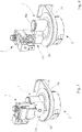
Figure 1 is an exploded perspective view of an air-gas mixer device according to the invention, shown interfaced with a fan and a valve unit for supplying gas to the device, -
Figure 2 is a further exploded perspective view of the assembly ofFigure 1 , -
Figure 3 and 4 are perspective views of the device of the preceding figures, shown in two different operating configurations of interfacing with the components of the assembly connected to it, -
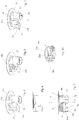
Figure 5 is a perspective view of a detail of the device of the preceding figures, -
Figures 6 and 7 are views, in side elevation and in longitudinal section respectively, of the detail ofFigure 5 , -
Figures 8 and 9 are views corresponding to that ofFigure 5 , in two different variant embodiments of the detail shown inFigure 5 , -
Figure 10 is an enlarged perspective view of a further detail of the device according to the invention, -
Figure 11 is a view in axial section of the mixer device of the invention shown interfaced with the fan and the valve unit; -
Figure 12 is a partial sectional view on an enlarged scale of a detail of the device ofFigure 11 , -
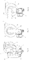
Figures 13 and 14 are views in side elevation of the device of the invention in a configuration of interfacing with a fan and a valve unit, -
Figure 15 is a plan view of the assembly ofFigures 13 and 14 . -
Figure 16 is a perspective view of the device of the invention in a variant embodiment of a detail of the device, -
Figure 17 is a view in side elevation of the device ofFigure 16 , -
Figure 18 is a view in side elevation of the device ofFigure 16 , in a different configuration, -
Figure 19 is a exploded perspective view of the device of the invention in a variant embodiment of a further detail of the device, and -
Figures 20 and 21 are views in front elevation of the device of the preceding figure, shown in two different operating configurations. - With reference to
Figure 1 initially, thenumber 1 indicates an air-gas mixer, designed particularly for burner equipment using gas fuel with premixing, made according to the present invention. - The
device 1 is designed to receive the air and gas flows introduced into the device, and to mix these flows to form an air-gas fuel mixture to be sent to theintake section 2a of acentrifugal fan 2, which in turn is designed to supply the air-gas fuel mixture, in delivery mode, to the head of a gas burner which is not shown. The invention is particularly, but not exclusively, applicable to the premixing of air and gas for burners of condensing boilers. Thenumber 3 indicates the whole of a valve unit through which the gas flow is supplied to the mixing area of themixer device 1. - More specifically, the mixer device comprises flow guide means for guiding the air flow into a mixing area into which the gas fuel flow is injected, and for guiding the fuel mixture to the intake section of the
fan 3. The fan comprises an impeller 4 driven in rotation about an axis indicated by X. The impeller 4 is housed in ascroll manifold 5 including ahousing 5a for receiving the impeller 4 and acover plate 5b to close the housing, this cover plate being connectable to the housing in the direction of the axis X. Acentral aperture 7 is formed in thecover plate 5b for communication with theintake section 2a of the fan. - The flow guide means of the
device 1 comprise a Venturi effecttubular conduit 6, with respective converging 6a and diverging 6b portions of conduit which are contiguous to one another and extend so as to prolong one another with an axially symmetrical development about the direction of an axis Y. An aperture 8, through which gas is injected into the mixing area of the Venturi conduit, extends across the converging and divergingportions 6a, 6b of the Venturi conduit. As is known, this intermediate area with a constricted cross section is the area in which the air flow passing through the Venturi conduit has a higher speed and a lower pressure, and the pressure drop signal that is generated serves to control thevalve unit 3 in a correlated way to deliver a suitable flow of gas to the mixing area. According to a principal characteristic of the invention, the axis of rotation X of thefan 2 does not coincide with the axis Y of axial development of the Venturiconduit 6 of the mixer, this non-coincidence possibly relating to the position of the axes, the direction of the axes, or both the position and the direction, in such a way that theconduit 6 is offset with a predetermined degree of eccentricity from themanifold 5 of the fan with which it is associated. - The offset between the axes X and Y, which are preferably parallel to each other, is chosen so as to allow the mounting on the
mixer device 1 of thevalve unit 3 with a configuration in which the projection of the overall dimensions of the Venturieffect conduit 6 and of thevalve unit 3, is substantially, and mainly, contained in the projection of thecover plate 5b of the fan, these projections being constructed along the axial direction (X). A configuration of this kind is clearly shown inFigures 13 - 15 , in which, owing to the eccentricity of themixer 1 relative to thefan 2, the overall dimensions of the mixer device together with thevalve unit 3 are contained within the spatial volume occupied by the fan in the direction of the axis X (and of the axis Y where it is parallel to this axis), thus achieving a high degree of compactness for the whole assembly formed by the mixer, fan and valve unit. - In the aforesaid figures, the distance between the axes X and Y, which is a measure of the eccentricity of the
mixer 1 relative to thefan 2, is indicated by D. - Returning to the
mixer device 1, in the examples described above, the structure of the tubular Venturieffect conduit 6, at least as regards the divergingportion 6b of the conduit, is conveniently made integral with, that is to say made in one piece with, thecover plate 5b that closes thefan manifold 5. - The
tubular conduit 6 is prolonged, downstream of the divergingportion 6b of the conduit, with respect to the direction of flow, into a bell-shaped portion 9 having no axial symmetry about the second axis Y, adapted to connect the divergingportion 6b to thecover plate 5b of the manifold, at theaperture 7 that puts the diverging portion of the Venturi conduit into communication with theintake section 2a of the fan. - The
cover plate 5b for closing thefan manifold 5 has aperimetric profile 5c of regular polygonal or circular shape (the latter of which is shown in the figures), which is concentric with the axis X of the impeller, so as to allow a plurality of possible relative coupling positions between thecover plate 5b and thehousing 5a of the fan manifold, so that, in each of these positions, it is possible to provide a respective different orientation of themixer device 1, and of thevalve unit 3 integral therewith, relative to the fan. Additionally, screw fastening means and counter-means (not shown) are provided between thecover plate 5b and thehousing 5a of thefan manifold 5, with a regular angular arrangement of the fastening holes formed in one and/or the other of thehousing 5a andcover plate 5b, so as to allow relative fastening in each of the coupling positions of the plurality of possible positions. This feature advantageously makes it possible to increase the number of degrees of freedom of the relative positioning between the mixer and the fan, in accordance with the requirements or the constraints of the installation, and according to the space available for each specific application. - The
mixer device 1 is also provided with ablock 10 for attaching thevalve unit 3 to the device, the block being preferably integral with, that is to say made in one piece with, both thecover plate 5b of the fan and the structure of the Venturiconduit 6, at least as regards thediverging portion 6b of the latter. - A
conduit 11 is formed in theblock 10, extending between a first end 11a, communicating with the aperture 8 in the Venturi conduit, and an opposed second end 11b intended to be put into communication with agas delivery aperture 12 provided in thevalve unit 3. - It should be noted that the offset D between the axes X and Y is chosen so that the structure of the Venturi
effect conduit 6 and theattachment block 10 for thevalve unit 3 have overall dimensions whose projection in the direction of the axis X is included within the corresponding projection of thecover plate 5b along the same axial direction X. This feature is, for example, clearly shown inFigures 5 to 7 . - The end 11a of the
conduit 11 opens into anannular chamber 13 delimited between the outer shells of the converging and divergingportions 6a, 6b and the inner wall of a cylindricaltubular portion 14 formed outside said portions and coaxial with them. Thechamber 13 also communicates with the aperture 8 for injecting the gas into the Venturi conduit, as described in greater detail below. - A
seat 15 is formed in theblock 10 to engage, with a sealed connection, with atubular delivery section 12a provided on thevalve unit 3 at thegas delivery aperture 12. Theseat 15 is formed in a cavity of the block extending between amouth 15a of the seat and anopposed base 15b into which the end 11b of theconduit 11 opens. - The perimetric contour of the cross section of the
seat 15 has a polygonal profile, preferably square (with rounded corners), as shown inFigures 5, 8 and 9 , which is capable of engaging, so as to substantially provide a positive coupling between the profiles, with a respective and corresponding polygonal profile, particularly a square profile, provided on thetubular section 12a of thevalve unit 3, the relative coupling between the respective profiles forming means for preventing the rotation of thevalve unit 3 relative to theattachment block 10 about the axial direction of insertion and extraction of the valve unit relative to theseat 15. - The
block 10 also has a parallelepipedal shape, in which theseat 15 for the attachment of the valve unit can be formed on at least one of at least four possible faces of the block, indicated by 10a - 10d, these faces being adjacent to one another, so as to provide four respective and different alternative positions of access to the block for the attachment of the valve unit to the mixer device, and, integrally with this device, to the fan. It should also be noted that, for each of these accesses, formed on one of thefaces 10a - 10d of the block, the provision of the square profile of theseat 15 allows four possible alternative orientations of the valve with respect to the block, this feature substantially increasing the number of degrees of freedom available to thevalve unit 3 for its attachment to themixer device 1. - The
number 16 indicates the whole of gas-tight locking means provided between thevalve unit 3 and theseat 15 of theattachment block 10, which are adapted to provide a gas-tight connection of the valve to the device, the gas-tight locking means also operating independently of the rotation prevention means formed by the polygonal profile of theseat 15. - These gas-tight locking means comprise a
transverse groove 18 provided in the outer shell of thetubular section 12a of thevalve unit 3 designed for axial fitting into theattachment seat 15 of theblock 10, and at least one retaining means held axially with respect to theseat 15 and extending, in part at least, in theseat 15 with an arrangement such that it engages thegroove 18 when thetubular section 12a of the valve unit is received in theseat 15, so as to lock theattachment block 10 and thevalve unit 3 together axially. - A sealing
ring 19 of the O-ring type is interposed between thetubular section 12a of the valve unit and the base 15b of theseat 15 to ensure gas-tightness between the coupled parts. - The sealing
ring 19 is housed, at least partially, in acavity 20 at the free end of thetubular section 12a of the valve unit, the sealing ring being compressible both in the axial direction of fitting into theseat 15 and in the radial direction, as a result of the action by which the valve unit is axially locked in the seat. - The axial retaining means is also removably engageable in the seat. In a first exemplary embodiment, the retaining means comprises a pair
cylindrical screws 21 capable of engaging, throughrespective holes 21a provided in theblock 10, theseat 15 transversely to the direction of axial fitting and on diametrically opposite sides of thegroove 18, so as to secure the action of axial retention of the valve unit with respect to the attachment block. - In a second exemplary embodiment, the retaining means is formed by a pair of opposing
branches 22, in the form of cylindrical pins, of a resilient fork-shapedclip 23. - As a further alternative, the axial retaining means comprises at least one locking
screw 24 engaged by screwing in a threadedhole 21b passing through theblock 10 transversely to the direction of axial fitting into theattachment seat 15, the end of thescrew 24 being capable of butting against the base of thegroove 18 of thetubular section 12a of the valve unit (when this is received in the seat), in order to secure its relative locking. - It should be noted that the compressive action on the sealing
ring 19 is exerted by thetubular section 12a as a result of the engagement of the retaining means in thegroove 18. - Returning to the structure of the
mixer device 1, the converging portion 6a of theVenturi effect conduit 6 is made structurally independent of the divergingportion 6b and can be fastened to theconduit structure 6 in a removable way. A bayonet coupling between theportions 6a and 6b is conveniently provided to form this removable connection. - In greater detail, the free section of the diverging
portion 6b, facing the converging portion, has at least a pair ofprojections 25, diametrically opposed and projecting radially inside theportion 6b, which are capable of engaging, by a bayonet coupling system, in respective axial retention seats 26 formed on the corresponding free end of the converging portion 6a facing the converging portion. Eachprojection 25 is retained axially between a respective pair ofstop surfaces - The converging portion 6a can be fitted axially into the cylindrical
tubular portion 14 and is provided with a sealingring 27 acting on the inner side wall of thecylindrical portion 14 to make theannular chamber 13 gas-tight towards the outside, once the converging portion 6a has been fitted by coupling to the divergingportion 6b. - It should be noted that the end section of the converging portion 6a extends for a certain distance into the end section of the diverging
portion 6b, this section of the converging portion having a smaller diameter than the diverging portion, such that an annular section is formed between these portions, creating the aperture 8 for the delivery of the gas flow into the mixing area inside the Venturi conduit. - Because of the configuration as described, the gas flow delivered through the aperture 8 flows into the area of mixing with the air in a direction having a predominantly axial component running parallel to the axis Y of the Venturi conduit.
- The
number 28 indicates recesses formed on the free end of the divergingportion 6b and open on the free end of this portion, these recesses being adapted to define the passage cross section of the gas flowing from theannular chamber 13 to the aperture 8 for delivering the gas into the Venturi conduit. - According to the invention, the converging portion 6a of the Venturi conduit is also designed to be structurally independent of the diverging
portion 6b, so as to be replaceable or interchangeable with other converging portions 6a having different dimensions, in particular as regards the size of the constricted cross section at the end of the converging portion, this size being correlated with the size of the aperture 8 for the passage of the gas into the air-gas mixing area of the Venturi conduit (as the diameter of the converging portion 6a decreases, the size of the aperture 8 increases), in order to enable the mixer device to be calibrated according to specific power ranges required in the burner of the boiler. - With particular reference to
Figure 16 , a manifold 29 is provided upstream of the converging portion 6a for the air flow sent from outside the mixer device. The manifold 29 has atubular portion 29a having a predominantly longitudinal extension, open towards the outside at one of its ends and connected at its opposite end to the free end of thetubular portion 14, at the position of the entry of air into the converging portion 6a of theVenturi conduit 6. In the aforesaid connecting area, the manifold 29 is shaped to impart a 90° deflection to the air flow guided in it, at the entry to the Venturi conduit, as clearly shown inFigure 16 . In other words, the manifold 29 is configured to be orientated substantially at a right angle to the axis X of the fan. - For the connection of the manifold 29 to the
tubular portion 14 of the mixer, a clamp type coupling between cylindrical profiles fitted into one another is conveniently provided. The circular coupling profile also enables the manifold 29 to be orientated with respect to themixer device 1 in a plurality of relative positions, and preferably in two different configurations, angled at 90° to one another, as shown, respectively, inFigures 17 and 18 . - With reference to
Figures 19 - 21 , in a variant embodiment of the device according to the invention, in which details corresponding to those of the preceding examples are identified by the same reference numerals, theperimetric profile 5c of the cover plate is made with atoothed edge 40. - The toothing of the edge is formed by a plurality of
recesses 41, having curved profiles, extending sequentially and contiguously to one another along the profile. A predetermined number of fastening holes 42 are provided on thehousing 5a to enable the cover plate to locked to the housing by means of screws. The locking system is such that the head of each screw can be received in acorresponding recess 41 in the edge, in order to fix a predetermined orientation between thecover plate 5b and thehousing 5a, the orientation being selected from a plurality of possible relative orientations provided by the toothed edge. Consequently, there is a plurality of possible orientations between the valve unit 3 (connected to the attachment block 10) and thefan 2. -
Figures 20 and 21 depict, by way of example, two different relative orientations between the cover plate and the housing which can be obtained, from among those made possible by the toothed edge configuration of the profile of the plate. - Thus the invention achieves the proposed objects while yielding the stated advantages by comparison with the known solutions.
- Among the advantages, mention should be made, in the first place, of the fact that, because of the provision of a mixer device configuration which is offset with respect to the fan, the space available for attaching the valve unit to the mixer device is increased, while the assembly of the components of the system has an improved capacity to match the possible configurations found in boiler layouts, determined by the available space and overall dimensions.
- The invention also makes it possible to increase substantially the relative positions and orientations between the components of the system, that is to say between the mixer, the fan and the valve unit, by increasing the capacity for mutual interfacing of these components, while preserving their functional characteristics.
- Another advantage is due to the fact that the increased capacity of the mixer device for interfacing with the other components is achieved in combination with a simplification of the construction of the device, with a consequent reduction in the costs of manufacture.
Claims (23)
- An air-gas mixer device for premix burner equipment of boilers, particularly of condensing boilers, comprising:flow guide means for guiding an air-gas mixture to the intake section (2a) of a centrifugal fan (2) with an impeller (4) driven in rotation about a first axis (X), the guide means including a tubular Venturi effect conduit structure (6) with contiguous converging and diverging portions (6a, 6b) developed in an axially symmetric manner about a second axis (Y), a section being provided between the portions of conduit into which section the gas flow is delivered for mixing with the air flow supplied through the converging portion (6a) of the conduit,the conduit (6) being in communication with the intake section (2a) of the fan, downstream of the diverging portion (6b) with respect to the direction of the flow,the impeller (4) of the fan being housed in a scroll manifold (5) including a housing (5a) for receiving the impeller (4) and a cover plate (5b) to close the housing (5a), a through aperture (7) being formed in the cover plate (5b) to put the Venturi effect conduit (6) into communication with the intake section (2a) of the fan,characterized in that the first axis (X) of rotation of the fan (2) does not coincide with the second axis (Y) of longitudinal development of the Venturi effect conduit (6), the offset between the first and second axes (X, Y) being chosen so as to allow the mixer device to have a valve unit (3) mounted on it for supplying the gas flow into the Venturi effect conduit (6) with a configuration in which the projection of the overall dimensions of the Venturi effect conduit (6) and of the valve unit (3), in the direction of the axis of rotation (X), lies substantially and predominantly within the projection of the cover plate (5b) of the fan in the direction of the first axis (X).
- A device according to Claim 1, wherein the first axis (X) of rotation of the fan (2) and the second axis (Y) of longitudinal development of the Venturi effect conduit structure (6) are parallel to each other, the distance between the first and second axes (X, Y) defining the offset (D) of the Venturi effect conduit from the intake section (2a) of the fan.
- A device according to Claim 1 or 2, wherein the structure of the tubular Venturi effect conduit (6), at least as regards the diverging portion (6b) of the conduit, is integral with the cover plate (5b) that closes the fan manifold (5).
- A device according to any one or more of the preceding claims, comprising a block (10) for the attachment of a valve unit (3) to the device, a conduit (11) being formed in this block (10) and extending between a first end (11a) in communication with the Venturi effect conduit (6) and an opposing second end (11b) designed to be put into communication with an aperture (12) for delivering gas from the valve unit (3), the offset (D) between the first and second axes (X, Y) being chosen so that the Venturi effect conduit structure (6) and the block (10) for attaching the valve unit (3) have total overall dimensions whose projection, at least in the direction of the first axis (X) of rotation, lies within the corresponding projection of the cover plate (5b) of the fan (2) constructed in the same direction as the first axis (X).
- A device according to Claim 4, wherein the attachment block (10) is integral with the Venturi effect conduit structure (6) and with the cover plate (5b) of the fan.
- A device according to any one or more of the preceding claims, wherein the tubular Venturi effect conduit structure (6) is prolonged, downstream of the diverging portion (6b) of the conduit, with respect to the direction of flow, into a bell-shaped portion (9) having no axial symmetry about the second axis (Y), adapted to connect the diverging portion (6b) of the conduit to the cover plate (5b) of the fan, the end section of the bell (9) putting the Venturi conduit of the mixer into communication with the intake section (2a) of the fan.
- A device according to any one or more of the preceding claims, wherein the cover plate (5b) for closing the fan manifold (5) has a perimetric profile (5c) of regular polygonal or circular shape, which is concentric with the axis (X) of the impeller, so as to allow a plurality of possible relative coupling positions between the cover plate (5b) and the housing (5a) of the fan manifold, so that, in each of these positions, it is possible to provide a respective orientation of the mixer device, and of the valve unit integral therewith, relative to the fan.
- A device according to Claim 7, wherein screw fastening means and counter-means are provided between the cover plate (5b) and the housing (5a) of the fan manifold, with a regular angular arrangement of the fastening holes formed in one and/or the other of the housing and cover plate, so as to allow relative fastening in each of the coupling positions of the plurality of possible positions.
- A device according to Claim 4, wherein the block (10) comprises a seat (15) for engaging and forming a sealed connection with a tubular delivery section (12a) provided on the valve unit, the seat (15) being formed in a cavity of the block (10) extending between a mouth (15a) of the seat and a base (15b) into which the auxiliary conduit (11) for communication with the Venturi effect conduit (6) opens, the perimetric contour of the cross section of the seat (15) having a polygonal profile capable of engaging, so as to substantially provide a positive coupling, with a respective and corresponding polygonal profile created on the tubular delivery section (12a) of the valve unit, the relative coupling between these profiles forming means for preventing the rotation of the valve unit (3) with respect to the attachment block (10) about the axial direction of insertion and extraction of the valve unit relative to the seat.
- A device according to Claim 9, wherein the aforesaid profile is square.
- A device according to Claim 9 or 10, wherein the attachment block (10) has a parallelepipedal shape and the seat (15) for engaging and forming a sealed connection with the valve unit is provided on one of at least four possible mutually adjacent faces (10a - d) of the block, so as to allow respective and different orientations of the seat (15), and of the valve unit (3) connected thereto, with respect to the mixer device and to the fan (2) which is integral therewith.
- A device according to Claim 9, wherein sealing locking means (16) are provided between the valve unit (3) and the seat (15) of the attachment block (10), these means being independent of the rotation prevention means formed by the polygonal profile of the seat (15).
- A device according to Claim 12, wherein the locking means comprise a transverse groove (18) provided in the outer shell of the tubular section (12a) of the valve unit designed for axial fitting into the attachment seat (15) of the block, and at least one retaining means held axially with respect to the seat and extending, in part at least, in the seat (15) with an arrangement such that it engages the groove (18) when the tubular section (12a) of the valve unit is received in the seat, so as to lock the attachment block (10) and the valve unit (3) together axially, a sealing means being interposed between the tubular section of the valve unit and the seat to ensure a gas-tight seal between the coupled parts.
- A device according to Claim 13, wherein the sealing means comprises a sealing ring (19), of the O-ring type, housed at least partially in a cavity (20) at the free end of the tubular section (12a) of the valve unit, the sealing ring being compressible both in the axial direction of fitting into the seat (15) and in the radial direction, as a result of the action by which the valve unit is axially locked in the seat.
- A device according to Claim 13, wherein the axial retaining means can be removably engaged in the seat (15).
- A device according to Claim 15, wherein the axial retaining means comprises a pair of retaining elements in the form of cylindrical plugs or screws capable of engaging the seat (15) transversely to the direction of axial fitting and on diametrically opposite sides of the groove (18), so as to secure the action of axial retention of the valve unit with respect to the attachment block.
- A device according to Claim 16, wherein the pair of cylindrical plug elements form the opposing branches (22) of a resilient fork-shaped clip (23).
- A device according to Claim 15, wherein the axial retaining means comprise at least one locking screw (24) engaged by screwing in a threaded hole (21b) passing through the block (10) transversely to the direction of axial fitting into the attachment seat (15), the end of the screw (24) being capable of butting against the outer shell of the tubular section (12a) of the valve unit received in the seat, in order to secure the locking of the valve unit relative to the attachment block.
- A device according to any one or more of the preceding claims, wherein the converging portion (6a) of the Venturi effect conduit is structurally independent of the diverging portion (6b) of the conduit, the converging portion being capable of being fastened removably to the Venturi effect conduit.
- A device according to Claim 19, wherein the converging and diverging portions (6a, 6b) of the Venturi effect conduit are fastened together by a bayonet coupling.
- A device according to any one or more of the preceding claims, wherein the free end of the converging portion (6a), facing the air-gas mixing area, extends inside the diverging portion (6b) and in a coaxial way, the converging portion having an end cross section with a smaller diameter than that of the diverging portion, such that an annular aperture is formed between the portions, through which the gas flow delivered by the valve unit is guided, with a predominantly axial direction of the flow, parallel to the axial direction of the Venturi conduit.
- A device according to Claims 4 and 21, wherein the converging and diverging portions (6a, 6b) of the Venturi effect conduit extend inside a cylindrical tubular portion of the mixer device, an annular chamber (13) being formed between the inner wall of the cylindrical portion and the outer shells of the converging and diverging portions, this chamber communicating, respectively, with the end section of the conduit for delivering gas from the valve unit and the annular aperture for delivering gas into the Venturi conduit.
- A device according to Claim 7 or 8, wherein the perimetric profile (5c) of the cover plate (5b) is provided with a toothed edge (40) including a predetermined number of recesses (41) extending in sequence contiguously to one another along the profile, fastening holes (42) being provided on the housing (5a) for locking the cover plate (5b) on to the housing (5a) by means of screws, the head of each screw being engageable with a corresponding recess (41) in the edge (40), in order to fix a predetermined orientation between the cover plate (5b) and the housing (5a), the predetermined orientation being selectable from a plurality of possible relative orientations provided by the toothed edge (40).
Priority Applications (1)
| Application Number | Priority Date | Filing Date | Title |
|---|---|---|---|
| PL14741386T PL3017250T3 (en) | 2013-07-05 | 2014-06-17 | An air-gas mixer device for premix burner equipment |
Applications Claiming Priority (2)
| Application Number | Priority Date | Filing Date | Title |
|---|---|---|---|
| IT000189A ITPD20130189A1 (en) | 2013-07-05 | 2013-07-05 | AIR-GAS MIXER DEVICE FOR PRE-MIXING BURNER EQUIPMENT |
| PCT/IB2014/062281 WO2015001438A1 (en) | 2013-07-05 | 2014-06-17 | An air-gas mixer device for premix burner equipment |
Publications (2)
| Publication Number | Publication Date |
|---|---|
| EP3017250A1 EP3017250A1 (en) | 2016-05-11 |
| EP3017250B1 true EP3017250B1 (en) | 2017-05-31 |
Family
ID=49118682
Family Applications (1)
| Application Number | Title | Priority Date | Filing Date |
|---|---|---|---|
| EP14741386.8A Not-in-force EP3017250B1 (en) | 2013-07-05 | 2014-06-17 | An air-gas mixer device for premix burner equipment |
Country Status (8)
| Country | Link |
|---|---|
| US (1) | US9677761B2 (en) |
| EP (1) | EP3017250B1 (en) |
| CN (1) | CN105612386B (en) |
| CA (1) | CA2915573A1 (en) |
| ES (1) | ES2638499T3 (en) |
| IT (1) | ITPD20130189A1 (en) |
| PL (1) | PL3017250T3 (en) |
| WO (1) | WO2015001438A1 (en) |
Cited By (1)
| Publication number | Priority date | Publication date | Assignee | Title |
|---|---|---|---|---|
| US11143399B2 (en) * | 2018-05-09 | 2021-10-12 | Paloma Co., Ltd | Premixing device and combustion device |
Families Citing this family (12)
| Publication number | Priority date | Publication date | Assignee | Title |
|---|---|---|---|---|
| US9746176B2 (en) | 2014-06-04 | 2017-08-29 | Lochinvar, Llc | Modulating burner with venturi damper |
| EP3015767B1 (en) * | 2014-10-29 | 2019-03-06 | Honeywell Technologies Sarl | Assembly comprising a gas valve and a gas/air mixer |
| JP6530275B2 (en) * | 2015-08-18 | 2019-06-12 | リンナイ株式会社 | Combustion device |
| EP3270060B1 (en) * | 2016-07-11 | 2019-11-27 | Electrolux Appliances Aktiebolag | Gas burner system for a gas cooking hob |
| TWI643668B (en) * | 2017-02-08 | 2018-12-11 | 關隆股份有限公司 | Gas mixer (1) |
| CN107255273B (en) * | 2017-04-13 | 2023-04-18 | 陈丽霞 | Energy-saving high-heat-efficiency furnace end |
| US10344968B2 (en) | 2017-05-05 | 2019-07-09 | Grand Mate Co., Ltd. | Gas mixer |
| DE102019109369A1 (en) * | 2019-04-09 | 2020-10-15 | Ebm-Papst Landshut Gmbh | Adapter device designed to be attached to a suction opening of a gas blower |
| USD1112623S1 (en) | 2020-05-19 | 2026-02-10 | Pittway Sarl | Jet for a gas burner |
| EP3913284B1 (en) | 2020-05-19 | 2023-10-18 | Pittway Sarl | Gas/air mixing device of a gas burner |
| CN116261625B (en) | 2020-07-28 | 2025-09-23 | 康明斯公司 | Gas fuel-air mixer with high mixing uniformity |
| DE102021108001A1 (en) | 2021-03-30 | 2022-10-06 | Vaillant Gmbh | Method of attaching a gas nozzle to a gas valve, gas nozzle and heater |
Family Cites Families (7)
| Publication number | Priority date | Publication date | Assignee | Title |
|---|---|---|---|---|
| EP0834695B1 (en) * | 1996-10-03 | 1999-09-01 | Siabs Industry S.R.L. | A device for supplying a gas-air mixture to burners, particularly for heating apparatuses |
| DE29803416U1 (en) * | 1998-02-27 | 1998-05-07 | Giersch GmbH, 58675 Hemer | Burners for liquid or gaseous fuels |
| FR2794521B1 (en) * | 1999-06-04 | 2001-07-13 | Geminox | FORCED VENTILATION GAS BURNER FOR BOILER |
| IT1391676B1 (en) * | 2008-11-07 | 2012-01-17 | Sit La Precisa Spa Con Socio Unico | GAS BURNER UNIT WITH PRE-MIXING |
| IT1395189B1 (en) * | 2009-07-22 | 2012-09-05 | Ln 2 Srl Socio Unico | AIR-GAS MIXER DEVICE, PARTICULARLY FOR PRE-MIXING BURNER APPLIANCES. |
| WO2012006166A2 (en) * | 2010-06-29 | 2012-01-12 | A.O. Smith Corporation | Blower assembly for use with gas powered appliance |
| ITPD20110372A1 (en) * | 2011-11-24 | 2013-05-25 | Ln 2 Srl Socio Unico | AIR-GAS MIXER DEVICE FOR COMBUSTIBLE GAS BURNERS WITH PRE-MIXING |
-
2013
- 2013-07-05 IT IT000189A patent/ITPD20130189A1/en unknown
-
2014
- 2014-06-17 WO PCT/IB2014/062281 patent/WO2015001438A1/en not_active Ceased
- 2014-06-17 EP EP14741386.8A patent/EP3017250B1/en not_active Not-in-force
- 2014-06-17 CA CA2915573A patent/CA2915573A1/en not_active Abandoned
- 2014-06-17 ES ES14741386.8T patent/ES2638499T3/en active Active
- 2014-06-17 US US14/902,159 patent/US9677761B2/en not_active Expired - Fee Related
- 2014-06-17 PL PL14741386T patent/PL3017250T3/en unknown
- 2014-06-17 CN CN201480037935.5A patent/CN105612386B/en not_active Expired - Fee Related
Cited By (1)
| Publication number | Priority date | Publication date | Assignee | Title |
|---|---|---|---|---|
| US11143399B2 (en) * | 2018-05-09 | 2021-10-12 | Paloma Co., Ltd | Premixing device and combustion device |
Also Published As
| Publication number | Publication date |
|---|---|
| ITPD20130189A1 (en) | 2015-01-06 |
| CN105612386B (en) | 2017-11-07 |
| CN105612386A (en) | 2016-05-25 |
| WO2015001438A1 (en) | 2015-01-08 |
| CA2915573A1 (en) | 2015-01-08 |
| US9677761B2 (en) | 2017-06-13 |
| ES2638499T3 (en) | 2017-10-23 |
| PL3017250T3 (en) | 2017-12-29 |
| US20160161114A1 (en) | 2016-06-09 |
| EP3017250A1 (en) | 2016-05-11 |
Similar Documents
| Publication | Publication Date | Title |
|---|---|---|
| US9677761B2 (en) | Air-gas mixer device for premix burner equipment | |
| CN107567569B (en) | Improved gas burner with multi-ring main flame | |
| EP2278224B1 (en) | Air-gas mixer device, particularly for premix burner | |
| US5611684A (en) | Fuel-air mixing unit | |
| US20050202361A1 (en) | Multi-gas cooker, with a rotary valve provided with interchangeable regulating means | |
| US20060175566A1 (en) | Rotary valve in a multi-gas cooker | |
| CN108139073A (en) | For the gas burner with multiple flame rings of cooking stove | |
| US12110707B2 (en) | Swimming pool/spa gas heater inlet mixer system and associated methods | |
| CN210107388U (en) | Venturi premixer and combustion apparatus | |
| CA2742758C (en) | A gas burner apparatus with pre-mixing | |
| EP2713037B1 (en) | Venturi insert for a carburetor, and carburetor, system and apparatus incorporating the same | |
| EP3396253B1 (en) | Fuel nozzle module | |
| US10835078B2 (en) | Gas tap for a gas burner, and a gas cooking appliance incorporating said gas tap | |
| JP6124596B2 (en) | Burner nozzle and flame detection structure | |
| CN219318430U (en) | Burner and kitchen range | |
| CN113785159B (en) | Gas Burner | |
| CN104235842A (en) | Dual pilot light burner for a household appliance | |
| CN222732816U (en) | Burner and burner | |
| CN222849232U (en) | Burner with a burner body | |
| CN213362470U (en) | Nozzle seat connection structure and gas stove | |
| CN219674214U (en) | Gas premixer and gas heating water heater thereof | |
| CN223768904U (en) | Annular air inlet combustor and gas stove | |
| KR20230063168A (en) | Burner | |
| CN121229911A (en) | burner | |
| CN119802598A (en) | Burner with annular air inlet and gas stove |
Legal Events
| Date | Code | Title | Description |
|---|---|---|---|
| PUAI | Public reference made under article 153(3) epc to a published international application that has entered the european phase |
Free format text: ORIGINAL CODE: 0009012 |
|
| 17P | Request for examination filed |
Effective date: 20151214 |
|
| AK | Designated contracting states |
Kind code of ref document: A1 Designated state(s): AL AT BE BG CH CY CZ DE DK EE ES FI FR GB GR HR HU IE IS IT LI LT LU LV MC MK MT NL NO PL PT RO RS SE SI SK SM TR |
|
| AX | Request for extension of the european patent |
Extension state: BA ME |
|
| DAX | Request for extension of the european patent (deleted) | ||
| GRAP | Despatch of communication of intention to grant a patent |
Free format text: ORIGINAL CODE: EPIDOSNIGR1 |
|
| INTG | Intention to grant announced |
Effective date: 20170124 |
|
| GRAS | Grant fee paid |
Free format text: ORIGINAL CODE: EPIDOSNIGR3 |
|
| GRAA | (expected) grant |
Free format text: ORIGINAL CODE: 0009210 |
|
| AK | Designated contracting states |
Kind code of ref document: B1 Designated state(s): AL AT BE BG CH CY CZ DE DK EE ES FI FR GB GR HR HU IE IS IT LI LT LU LV MC MK MT NL NO PL PT RO RS SE SI SK SM TR |
|
| REG | Reference to a national code |
Ref country code: CH Ref legal event code: EP Ref country code: GB Ref legal event code: FG4D |
|
| REG | Reference to a national code |
Ref country code: AT Ref legal event code: REF Ref document number: 897844 Country of ref document: AT Kind code of ref document: T Effective date: 20170615 |
|
| REG | Reference to a national code |
Ref country code: IE Ref legal event code: FG4D |
|
| REG | Reference to a national code |
Ref country code: DE Ref legal event code: R096 Ref document number: 602014010336 Country of ref document: DE Ref country code: FR Ref legal event code: PLFP Year of fee payment: 4 |
|
| REG | Reference to a national code |
Ref country code: NL Ref legal event code: FP |
|
| REG | Reference to a national code |
Ref country code: LT Ref legal event code: MG4D |
|
| REG | Reference to a national code |
Ref country code: ES Ref legal event code: FG2A Ref document number: 2638499 Country of ref document: ES Kind code of ref document: T3 Effective date: 20171023 |
|
| PG25 | Lapsed in a contracting state [announced via postgrant information from national office to epo] |
Ref country code: HR Free format text: LAPSE BECAUSE OF FAILURE TO SUBMIT A TRANSLATION OF THE DESCRIPTION OR TO PAY THE FEE WITHIN THE PRESCRIBED TIME-LIMIT Effective date: 20170531 Ref country code: NO Free format text: LAPSE BECAUSE OF FAILURE TO SUBMIT A TRANSLATION OF THE DESCRIPTION OR TO PAY THE FEE WITHIN THE PRESCRIBED TIME-LIMIT Effective date: 20170831 Ref country code: FI Free format text: LAPSE BECAUSE OF FAILURE TO SUBMIT A TRANSLATION OF THE DESCRIPTION OR TO PAY THE FEE WITHIN THE PRESCRIBED TIME-LIMIT Effective date: 20170531 Ref country code: LT Free format text: LAPSE BECAUSE OF FAILURE TO SUBMIT A TRANSLATION OF THE DESCRIPTION OR TO PAY THE FEE WITHIN THE PRESCRIBED TIME-LIMIT Effective date: 20170531 Ref country code: GR Free format text: LAPSE BECAUSE OF FAILURE TO SUBMIT A TRANSLATION OF THE DESCRIPTION OR TO PAY THE FEE WITHIN THE PRESCRIBED TIME-LIMIT Effective date: 20170901 |
|
| PG25 | Lapsed in a contracting state [announced via postgrant information from national office to epo] |
Ref country code: IS Free format text: LAPSE BECAUSE OF FAILURE TO SUBMIT A TRANSLATION OF THE DESCRIPTION OR TO PAY THE FEE WITHIN THE PRESCRIBED TIME-LIMIT Effective date: 20170930 Ref country code: SE Free format text: LAPSE BECAUSE OF FAILURE TO SUBMIT A TRANSLATION OF THE DESCRIPTION OR TO PAY THE FEE WITHIN THE PRESCRIBED TIME-LIMIT Effective date: 20170531 Ref country code: RS Free format text: LAPSE BECAUSE OF FAILURE TO SUBMIT A TRANSLATION OF THE DESCRIPTION OR TO PAY THE FEE WITHIN THE PRESCRIBED TIME-LIMIT Effective date: 20170531 Ref country code: LV Free format text: LAPSE BECAUSE OF FAILURE TO SUBMIT A TRANSLATION OF THE DESCRIPTION OR TO PAY THE FEE WITHIN THE PRESCRIBED TIME-LIMIT Effective date: 20170531 Ref country code: BG Free format text: LAPSE BECAUSE OF FAILURE TO SUBMIT A TRANSLATION OF THE DESCRIPTION OR TO PAY THE FEE WITHIN THE PRESCRIBED TIME-LIMIT Effective date: 20170831 |
|
| PG25 | Lapsed in a contracting state [announced via postgrant information from national office to epo] |
Ref country code: DK Free format text: LAPSE BECAUSE OF FAILURE TO SUBMIT A TRANSLATION OF THE DESCRIPTION OR TO PAY THE FEE WITHIN THE PRESCRIBED TIME-LIMIT Effective date: 20170531 Ref country code: EE Free format text: LAPSE BECAUSE OF FAILURE TO SUBMIT A TRANSLATION OF THE DESCRIPTION OR TO PAY THE FEE WITHIN THE PRESCRIBED TIME-LIMIT Effective date: 20170531 Ref country code: RO Free format text: LAPSE BECAUSE OF FAILURE TO SUBMIT A TRANSLATION OF THE DESCRIPTION OR TO PAY THE FEE WITHIN THE PRESCRIBED TIME-LIMIT Effective date: 20170531 Ref country code: SK Free format text: LAPSE BECAUSE OF FAILURE TO SUBMIT A TRANSLATION OF THE DESCRIPTION OR TO PAY THE FEE WITHIN THE PRESCRIBED TIME-LIMIT Effective date: 20170531 Ref country code: CZ Free format text: LAPSE BECAUSE OF FAILURE TO SUBMIT A TRANSLATION OF THE DESCRIPTION OR TO PAY THE FEE WITHIN THE PRESCRIBED TIME-LIMIT Effective date: 20170531 |
|
| REG | Reference to a national code |
Ref country code: CH Ref legal event code: PL |
|
| PG25 | Lapsed in a contracting state [announced via postgrant information from national office to epo] |
Ref country code: SM Free format text: LAPSE BECAUSE OF FAILURE TO SUBMIT A TRANSLATION OF THE DESCRIPTION OR TO PAY THE FEE WITHIN THE PRESCRIBED TIME-LIMIT Effective date: 20170531 |
|
| REG | Reference to a national code |
Ref country code: DE Ref legal event code: R097 Ref document number: 602014010336 Country of ref document: DE |
|
| REG | Reference to a national code |
Ref country code: IE Ref legal event code: MM4A |
|
| PLBE | No opposition filed within time limit |
Free format text: ORIGINAL CODE: 0009261 |
|
| STAA | Information on the status of an ep patent application or granted ep patent |
Free format text: STATUS: NO OPPOSITION FILED WITHIN TIME LIMIT |
|
| PG25 | Lapsed in a contracting state [announced via postgrant information from national office to epo] |
Ref country code: LU Free format text: LAPSE BECAUSE OF NON-PAYMENT OF DUE FEES Effective date: 20170617 Ref country code: LI Free format text: LAPSE BECAUSE OF NON-PAYMENT OF DUE FEES Effective date: 20170630 Ref country code: CH Free format text: LAPSE BECAUSE OF NON-PAYMENT OF DUE FEES Effective date: 20170630 Ref country code: IE Free format text: LAPSE BECAUSE OF NON-PAYMENT OF DUE FEES Effective date: 20170617 |
|
| 26N | No opposition filed |
Effective date: 20180301 |
|
| PG25 | Lapsed in a contracting state [announced via postgrant information from national office to epo] |
Ref country code: SI Free format text: LAPSE BECAUSE OF FAILURE TO SUBMIT A TRANSLATION OF THE DESCRIPTION OR TO PAY THE FEE WITHIN THE PRESCRIBED TIME-LIMIT Effective date: 20170531 |
|
| REG | Reference to a national code |
Ref country code: FR Ref legal event code: PLFP Year of fee payment: 5 |
|
| PG25 | Lapsed in a contracting state [announced via postgrant information from national office to epo] |
Ref country code: MT Free format text: LAPSE BECAUSE OF NON-PAYMENT OF DUE FEES Effective date: 20170617 |
|
| PG25 | Lapsed in a contracting state [announced via postgrant information from national office to epo] |
Ref country code: HU Free format text: LAPSE BECAUSE OF FAILURE TO SUBMIT A TRANSLATION OF THE DESCRIPTION OR TO PAY THE FEE WITHIN THE PRESCRIBED TIME-LIMIT; INVALID AB INITIO Effective date: 20140617 Ref country code: MC Free format text: LAPSE BECAUSE OF FAILURE TO SUBMIT A TRANSLATION OF THE DESCRIPTION OR TO PAY THE FEE WITHIN THE PRESCRIBED TIME-LIMIT Effective date: 20170531 |
|
| PGFP | Annual fee paid to national office [announced via postgrant information from national office to epo] |
Ref country code: IT Payment date: 20190521 Year of fee payment: 6 Ref country code: PL Payment date: 20190611 Year of fee payment: 6 Ref country code: DE Payment date: 20190619 Year of fee payment: 6 Ref country code: NL Payment date: 20190619 Year of fee payment: 6 |
|
| PGFP | Annual fee paid to national office [announced via postgrant information from national office to epo] |
Ref country code: TR Payment date: 20190611 Year of fee payment: 6 Ref country code: BE Payment date: 20190619 Year of fee payment: 6 Ref country code: FR Payment date: 20190619 Year of fee payment: 6 |
|
| PG25 | Lapsed in a contracting state [announced via postgrant information from national office to epo] |
Ref country code: CY Free format text: LAPSE BECAUSE OF FAILURE TO SUBMIT A TRANSLATION OF THE DESCRIPTION OR TO PAY THE FEE WITHIN THE PRESCRIBED TIME-LIMIT Effective date: 20170531 |
|
| PGFP | Annual fee paid to national office [announced via postgrant information from national office to epo] |
Ref country code: ES Payment date: 20190722 Year of fee payment: 6 Ref country code: GB Payment date: 20190619 Year of fee payment: 6 Ref country code: AT Payment date: 20190621 Year of fee payment: 6 |
|
| PG25 | Lapsed in a contracting state [announced via postgrant information from national office to epo] |
Ref country code: MK Free format text: LAPSE BECAUSE OF FAILURE TO SUBMIT A TRANSLATION OF THE DESCRIPTION OR TO PAY THE FEE WITHIN THE PRESCRIBED TIME-LIMIT Effective date: 20170531 |
|
| REG | Reference to a national code |
Ref country code: AT Ref legal event code: UEP Ref document number: 897844 Country of ref document: AT Kind code of ref document: T Effective date: 20170531 |
|
| PG25 | Lapsed in a contracting state [announced via postgrant information from national office to epo] |
Ref country code: PT Free format text: LAPSE BECAUSE OF FAILURE TO SUBMIT A TRANSLATION OF THE DESCRIPTION OR TO PAY THE FEE WITHIN THE PRESCRIBED TIME-LIMIT Effective date: 20170531 |
|
| PG25 | Lapsed in a contracting state [announced via postgrant information from national office to epo] |
Ref country code: AL Free format text: LAPSE BECAUSE OF FAILURE TO SUBMIT A TRANSLATION OF THE DESCRIPTION OR TO PAY THE FEE WITHIN THE PRESCRIBED TIME-LIMIT Effective date: 20170531 |
|
| REG | Reference to a national code |
Ref country code: DE Ref legal event code: R119 Ref document number: 602014010336 Country of ref document: DE |
|
| REG | Reference to a national code |
Ref country code: NL Ref legal event code: MM Effective date: 20200701 |
|
| REG | Reference to a national code |
Ref country code: AT Ref legal event code: MM01 Ref document number: 897844 Country of ref document: AT Kind code of ref document: T Effective date: 20200617 |
|
| GBPC | Gb: european patent ceased through non-payment of renewal fee |
Effective date: 20200617 |
|
| REG | Reference to a national code |
Ref country code: BE Ref legal event code: MM Effective date: 20200630 |
|
| PG25 | Lapsed in a contracting state [announced via postgrant information from national office to epo] |
Ref country code: FR Free format text: LAPSE BECAUSE OF NON-PAYMENT OF DUE FEES Effective date: 20200630 Ref country code: NL Free format text: LAPSE BECAUSE OF NON-PAYMENT OF DUE FEES Effective date: 20200701 Ref country code: GB Free format text: LAPSE BECAUSE OF NON-PAYMENT OF DUE FEES Effective date: 20200617 |
|
| PG25 | Lapsed in a contracting state [announced via postgrant information from national office to epo] |
Ref country code: BE Free format text: LAPSE BECAUSE OF NON-PAYMENT OF DUE FEES Effective date: 20200630 Ref country code: AT Free format text: LAPSE BECAUSE OF NON-PAYMENT OF DUE FEES Effective date: 20200617 Ref country code: DE Free format text: LAPSE BECAUSE OF NON-PAYMENT OF DUE FEES Effective date: 20210101 |
|
| PG25 | Lapsed in a contracting state [announced via postgrant information from national office to epo] |
Ref country code: IT Free format text: LAPSE BECAUSE OF NON-PAYMENT OF DUE FEES Effective date: 20200617 |
|
| PG25 | Lapsed in a contracting state [announced via postgrant information from national office to epo] |
Ref country code: ES Free format text: LAPSE BECAUSE OF NON-PAYMENT OF DUE FEES Effective date: 20200618 |
|
| PG25 | Lapsed in a contracting state [announced via postgrant information from national office to epo] |
Ref country code: TR Free format text: LAPSE BECAUSE OF NON-PAYMENT OF DUE FEES Effective date: 20200617 |
|
| PG25 | Lapsed in a contracting state [announced via postgrant information from national office to epo] |
Ref country code: PL Free format text: LAPSE BECAUSE OF NON-PAYMENT OF DUE FEES Effective date: 20200617 |