EP3016997B1 - Method and plant for etching a fluoropolymer substrate - Google Patents
Method and plant for etching a fluoropolymer substrate Download PDFInfo
- Publication number
- EP3016997B1 EP3016997B1 EP13815590.8A EP13815590A EP3016997B1 EP 3016997 B1 EP3016997 B1 EP 3016997B1 EP 13815590 A EP13815590 A EP 13815590A EP 3016997 B1 EP3016997 B1 EP 3016997B1
- Authority
- EP
- European Patent Office
- Prior art keywords
- solution
- washing
- adhesion
- inverse osmosis
- acetic acid
- Prior art date
- Legal status (The legal status is an assumption and is not a legal conclusion. Google has not performed a legal analysis and makes no representation as to the accuracy of the status listed.)
- Active
Links
Images



Classifications
-
- C—CHEMISTRY; METALLURGY
- C08—ORGANIC MACROMOLECULAR COMPOUNDS; THEIR PREPARATION OR CHEMICAL WORKING-UP; COMPOSITIONS BASED THEREON
- C08J—WORKING-UP; GENERAL PROCESSES OF COMPOUNDING; AFTER-TREATMENT NOT COVERED BY SUBCLASSES C08B, C08C, C08F, C08G or C08H
- C08J7/00—Chemical treatment or coating of shaped articles made of macromolecular substances
- C08J7/12—Chemical modification
- C08J7/14—Chemical modification with acids, their salts or anhydrides
-
- B—PERFORMING OPERATIONS; TRANSPORTING
- B01—PHYSICAL OR CHEMICAL PROCESSES OR APPARATUS IN GENERAL
- B01D—SEPARATION
- B01D61/00—Processes of separation using semi-permeable membranes, e.g. dialysis, osmosis or ultrafiltration; Apparatus, accessories or auxiliary operations specially adapted therefor
- B01D61/02—Reverse osmosis; Hyperfiltration ; Nanofiltration
- B01D61/025—Reverse osmosis; Hyperfiltration
-
- B—PERFORMING OPERATIONS; TRANSPORTING
- B01—PHYSICAL OR CHEMICAL PROCESSES OR APPARATUS IN GENERAL
- B01D—SEPARATION
- B01D61/00—Processes of separation using semi-permeable membranes, e.g. dialysis, osmosis or ultrafiltration; Apparatus, accessories or auxiliary operations specially adapted therefor
- B01D61/58—Multistep processes
-
- B—PERFORMING OPERATIONS; TRANSPORTING
- B01—PHYSICAL OR CHEMICAL PROCESSES OR APPARATUS IN GENERAL
- B01D—SEPARATION
- B01D69/00—Semi-permeable membranes for separation processes or apparatus characterised by their form, structure or properties; Manufacturing processes specially adapted therefor
- B01D69/10—Supported membranes; Membrane supports
- B01D69/107—Organic support material
- B01D69/1071—Woven, non-woven or net mesh
-
- B—PERFORMING OPERATIONS; TRANSPORTING
- B01—PHYSICAL OR CHEMICAL PROCESSES OR APPARATUS IN GENERAL
- B01D—SEPARATION
- B01D69/00—Semi-permeable membranes for separation processes or apparatus characterised by their form, structure or properties; Manufacturing processes specially adapted therefor
- B01D69/12—Composite membranes; Ultra-thin membranes
- B01D69/1213—Laminated layers
-
- C—CHEMISTRY; METALLURGY
- C08—ORGANIC MACROMOLECULAR COMPOUNDS; THEIR PREPARATION OR CHEMICAL WORKING-UP; COMPOSITIONS BASED THEREON
- C08J—WORKING-UP; GENERAL PROCESSES OF COMPOUNDING; AFTER-TREATMENT NOT COVERED BY SUBCLASSES C08B, C08C, C08F, C08G or C08H
- C08J7/00—Chemical treatment or coating of shaped articles made of macromolecular substances
- C08J7/02—Chemical treatment or coating of shaped articles made of macromolecular substances with solvents, e.g. swelling agents
-
- B—PERFORMING OPERATIONS; TRANSPORTING
- B01—PHYSICAL OR CHEMICAL PROCESSES OR APPARATUS IN GENERAL
- B01D—SEPARATION
- B01D2311/00—Details relating to membrane separation process operations and control
- B01D2311/06—Specific process operations in the permeate stream
-
- B—PERFORMING OPERATIONS; TRANSPORTING
- B01—PHYSICAL OR CHEMICAL PROCESSES OR APPARATUS IN GENERAL
- B01D—SEPARATION
- B01D2311/00—Details relating to membrane separation process operations and control
- B01D2311/26—Further operations combined with membrane separation processes
- B01D2311/263—Chemical reaction
-
- B—PERFORMING OPERATIONS; TRANSPORTING
- B01—PHYSICAL OR CHEMICAL PROCESSES OR APPARATUS IN GENERAL
- B01D—SEPARATION
- B01D2311/00—Details relating to membrane separation process operations and control
- B01D2311/26—Further operations combined with membrane separation processes
- B01D2311/263—Chemical reaction
- B01D2311/2634—Oxidation
-
- B—PERFORMING OPERATIONS; TRANSPORTING
- B01—PHYSICAL OR CHEMICAL PROCESSES OR APPARATUS IN GENERAL
- B01D—SEPARATION
- B01D2311/00—Details relating to membrane separation process operations and control
- B01D2311/26—Further operations combined with membrane separation processes
- B01D2311/2669—Distillation
-
- B—PERFORMING OPERATIONS; TRANSPORTING
- B01—PHYSICAL OR CHEMICAL PROCESSES OR APPARATUS IN GENERAL
- B01D—SEPARATION
- B01D2311/00—Details relating to membrane separation process operations and control
- B01D2311/26—Further operations combined with membrane separation processes
- B01D2311/2688—Biological processes
-
- C—CHEMISTRY; METALLURGY
- C08—ORGANIC MACROMOLECULAR COMPOUNDS; THEIR PREPARATION OR CHEMICAL WORKING-UP; COMPOSITIONS BASED THEREON
- C08J—WORKING-UP; GENERAL PROCESSES OF COMPOUNDING; AFTER-TREATMENT NOT COVERED BY SUBCLASSES C08B, C08C, C08F, C08G or C08H
- C08J2327/00—Characterised by the use of homopolymers or copolymers of compounds having one or more unsaturated aliphatic radicals, each having only one carbon-to-carbon double bond, and at least one being terminated by a halogen; Derivatives of such polymers
- C08J2327/02—Characterised by the use of homopolymers or copolymers of compounds having one or more unsaturated aliphatic radicals, each having only one carbon-to-carbon double bond, and at least one being terminated by a halogen; Derivatives of such polymers not modified by chemical after-treatment
- C08J2327/12—Characterised by the use of homopolymers or copolymers of compounds having one or more unsaturated aliphatic radicals, each having only one carbon-to-carbon double bond, and at least one being terminated by a halogen; Derivatives of such polymers not modified by chemical after-treatment containing fluorine atoms
- C08J2327/18—Homopolymers or copolymers of tetrafluoroethylene
Definitions
- the present invention relates to a method and a plant for treating a fluoropolymer substrate, and in particular, a method/plant for etching a fluoropolymer substrate to increase the surface adhesion of such substrate.
- PTFE polytetrafluoroethylene
- the chemical resistance of polytetrafluoroethylene (PTFE) is a feature which has made such fluoropolymer extremely desirable in the chemical industry, for example for coating reactors or piping, in the presence of reactions by their nature aggressive.
- PTFE has replaced asbestos - today banned by law given its carcinogenic nature - in a plurality of applications, such as for example coating high temperature cables.
- the biocompatibility of PTFE has led the biomedical industry to use it to make implantable elements and in medical devices to be used inside the human body.
- the unique nature of the dielectric properties of fluoropolymers in general, and of PTFE in particular, has allowed the development of a new market in the printed circuit boards sector.
- a first purpose of the present invention is therefore to provide a method, and a relative plant, able to perform the etching of PTFE on an industrial scale and in conditions of extreme safety. It is a further purpose of the present invention to provide a method and a plant integrated within themselves, but above all clean from an environmental point of view, able to drastically reduce the quantity of pollutants released in an act of responsible sacrifice.
- reference numeral 4 refers both to the step of washing the primary surface and to the removal bath in which such step is performed.
- the present etching method which, as said, is used to increase the surface adhesion of a fluoropolymer substrate 10, comprises a first step of feeding 22 such fluoropolymer substrate in the form of a continuous ribbon or film along a feeding direction X, where such substrate defines at least a primary surface 12.
- a substrate is a substrate in polytetrafluoroethylene (PTFE).
- PTFE polytetrafluoroethylene
- the fluoropolymer is selected from the group consisting in PTFE, fluorinated ethylene propylene (FEP), perfluoroalkoxy (PFA), polyvinylidene fluoride (PVDF) - or the like - and mixtures thereof.
- the present method is a (semi)-continuous etching method, which is performed at least on the primary surface which is thus the surface which at the end of the steps discussed below will prove to have improved surface adhesion.
- etching is understood to mean a chemical process suitable for making the fluoropolymer substrate suitable for gluing to other surfaces, by improving its adhesive properties.
- feed direction X is understood to mean directions of supplying the substrate not necessarily rectilinear, though some variants may provide for such. However, such term will also and above all be understood as a direction roughly parallel to the main extension of the fluoropolymer ribbon or film having a "complex" pattern, that is to say a succession of loops, curves, straight sections etc.
- the entire continuous fluoropolymer ribbon or film is subjected to etching, so that in such case not only the primary surface 12 but also an opposite surface 32 delimiting the thickness the ribbon or film will undergo such treatment.
- a connection surface 36 connecting such surfaces 12, 32 may also be etched or not.
- one embodiment provides that the entire substrate is immersed in or at least wetted by the adhesion-promoting solution.
- At least a part of the primary surface 12 is subjected to one or more etching operations 2 by means of an adhesion-promoting solution comprising a complex of an alkali metal in naphthalene.
- an adhesion-promoting solution comprising a complex of an alkali metal in naphthalene.
- the alkali metal used is sodium, in as much as deemed by the authors of the present invention as one of the most reliable chemical abrasives of fluoropolymers.
- Further embodiments may provide for the use of lithium, potassium or mixtures thereof, (including mixtures of the same with sodium).
- the adhesion-promoting solution is produced by means of a solubilisation/reaction 20, 20' which is preferably performed in situ , between diethylene glycol dimethyl ether, the alkali metal and the naphthalene.
- the advantages related to the use of diethylene glycol dimethyl ether are the high level of stability at ambient temperatures (and even slightly over ambient temperatures), the reduced inflammability with a flash point of approximately 57°C, and the viscosity similar to that of water which it gives to the adhesion-promoting solution, such latter being a significant technological advantage. Added to this is a sufficient propensity of such mixture to "wet" the surfaces of the fluoropolymer substrate.
- the part of the primary surface 12 wetted by the adhesion-promoting solution is washed 4 by means of a washing solution 42 comprising aqueous acetic acid or aqueous formic acid.
- a step of winding 34 the continuous ribbon or film of fluoropolymer substrate 10 in one or more collection bobbins is provided for, which can thus be stored.
- the step of washing with the washing solution 42 may be preceded by a first step of pre-washing 14 in an organic phase (comprising or consisting for example of diethylene glycol dimethyl ether), and of a second step of pre-washing 16 in an aqueous phase with water at a temperature above ambient temperature.
- the organic phase may be purified, for example distilled 18, and may be re-introduced in the first pre-washing step 14.
- the washing step may be followed by a step of drying the continuous ribbon or film of fluoropolymer substrate 10, for example at a temperature of approximately 50°C - 100°C, preferably of approximately 60° - 80°C.
- a drying oven downstream of the removal bath 4 discussed below a drying oven could be provided.
- a concentrated solution 24 of acetic acid, or of formic acid for some variants is selectively separated from the washing solution 42 by means of inverse osmosis operations 6, 8 at increasing pressure.
- inverse osmosis operations 6, 8 The use of reverse-osmosis membranes processing highly alkaline solutions for recovering valuable materials and minimize waste generation in processing mine, mineral ore extracts is known in US 2008/277342 .
- the separation step foresees a previous operation of inverse osmosis 6 (at a first pressure P1) and a subsequent operation of inverse osmosis 8 (at a second pressure P2), wherein said latter operation takes place at a higher pressure than the pressure P1 (P2 > P1 or P >>P1).
- the second pressure P2 may be approximately 2-10 times the first pressure P1 used in the previous operation 6.
- the separation step comprises a first (or previous) 6 and a second (or subsequent) 8 operation of inverse osmosis, the second operation being conducted on a concentrated fraction 44 coming from the first operation.
- first (or previous) 6 and a second (or subsequent) 8 operation of inverse osmosis the second operation being conducted on a concentrated fraction 44 coming from the first operation.
- first concentrated fraction 44 proceeds towards the second inverse osmosis operation leaving a first permeated fraction 46 from the first inverse osmosis operation 6, such permeated fraction 46 may be subjected to one or more steps selected from the group consisting in oxidation, bacterial oxidation, ultrafiltration, immersed membrane ultrafiltration, reuse and/or drainage, despite the last being the least preferred of the embodiments.
- a second permeated fraction 48 of the second inverse osmosis operation 8 forms the concentrated solution 24 of acetic acid or of formic acid.
- the presence of an increased pressure in the second operation 8 causes an enrichment of acetic acid (or formic acid) in the second permeated fraction 48, since the latter has a titre substantially corresponding to the concentrated solution 24.
- the second permeated fraction 48 could have an acid concentration even higher than that needed for the washing solution 42. In such case, it could be preferable to dilute the concentrated acid solution, for example by means of the water used in the second pre-washing step 16.
- the method according to the present invention further comprises a step of introducing at least a portion of the concentrated solution of acetic acid 24 or of formic acid in the washing solution 42 to thus create a recirculation.
- the present invention further relates to a (semi-)continuous etching plant 1 for increasing the surface adhesion of a fluoropolymer substrate 10.
- a (semi-)continuous etching plant 1 for increasing the surface adhesion of a fluoropolymer substrate 10.
- such plant has proved particularly suitable for implementing the method just discussed above so that, even where not expressly specified, such plant provides for all the technical means needed to conduct any of the previous steps of the method.
- the plant 1 comprises feeding means 22 of the fluoropolymer substrate 10 in the form of a continuous ribbon or film along a feeding direction X, said substrate delimiting the primary surface 12 and preferably the opposite surface 32
- the feeding means 22 comprise one or more feed bobbins, from which the fluoropolymer substrate is progressively unwound in the direction X.
- the feeding means may comprise a production plant of the substrate in fluoropolymer. Consequently, in such variant, the winding of the aforesaid substrate onto bobbins becomes superfluous, in that the plant according to the present invention may be positioned directly downstream of a fluoropolymer production plant.
- upstream and downstream are understood to mean the apparatus positioned respectively before or after the appliances specified in relation to the feed direction X, or in relation to the flow direction of the specified process fluids.
- the plant 1 further foresees one or more etching tanks 2 containing the adhesion-promoting solution comprising the complex of the alkali metal in naphthalene for the chemical attack of at least a part of the primary surface 12. This way the etching at least of such surface takes place.
- the fluoropolymer ribbon or film may be immersed in said tank 2, or may lick the free surface of the tank so that only one surface undergoes the chemical attack.
- the system disclosed in the publication US4637856 could be used.
- the plant 1 comprises a plurality of return calenders 28, 28' for the continuous fluoropolymer substrate 10, positioned and distanced along the feed direction X to immerse the substrate 10 in the adhesion-promoting solution and/or in the washing solution, and optionally in the organic phase and/or aqueous phase.
- the plant 1 comprises at least one synthesis reactor 20, 20' in which the washing solution is produced by means of an in situ reaction between diethylene glycol dimethyl ether, the alkali metal and the naphthalene.
- Such reactor is preferably fluidically connected to the etching tank 2 or to the plurality thereof.
- a pair of synthesis reactors 20, 20' positioned parallel to each other may be provided.
- the plant 1 further comprises a removal bath 4 of the adhesion-promoting solution from the part of the primary surface 12 wetted by said solution, wherein the removal bath contains the washing solution comprising aqueous acetic acid or aqueous formic acid.
- the plant downstream of the removal bath 4, the plant comprises at least one collection bobbin 34 of the fluoropolymer substrate of increased surface adhesion.
- the plant 1 upstream of the removal bath 4 of the adhesion-promoting solution, may comprise a first pre-washing bath 14 in the organic phase (in particular comprising diethylene glycol dimethyl ether), and a second pre-washing bath 16 in the aqueous phase, for example containing water at a temperature above ambient temperature.
- a first pre-washing bath 14 in the organic phase in particular comprising diethylene glycol dimethyl ether
- a second pre-washing bath 16 in the aqueous phase, for example containing water at a temperature above ambient temperature.
- distillation means 18 of the organic phase may also be provided, fluidically communicating with said first pre-washing bath 14 so as to create a secondary recirculation.
- the organic phase could be withdrawn from the first bath 14 (via the line 38 in figure 1 ), and re-emitted (line 40) following an at least partial purification in said first pre-washing bath 14 in a preferably (semi-)continuous manner.
- the plant 1 further comprises inverse osmosis stations 6, 8 working at increasing pressures P1, P2 configured to selectively separate the concentrated solution 24 of acetic acid or of formic acid from the washing solution.
- At least one inverse osmosis station (6 or 8 but preferably both stations 6, 8) preferably comprises a multi-layer separation membrane comprising a non-woven support layer, an intermediate micro-porous layer, and a protective layer of the intermediate layer.
- the support layer comprises polyester
- the intermediate layer is polysulfonic
- the protective layer is a coating applied to the intermediate layer.
- the protective layer has a thickness of approximately 2500 ⁇ ngstrom (250 nm) or less, and preferably of approximately 2000 ⁇ ngstrom (200 nm).
- one possible membrane which could be used in the aforesaid inverse osmosis station is made by "The Dow Chemical Company" under the brand name "Filmtec® FT30 Membrane”.
- the plant 1 further comprises means for re-introducing 26 at least a portion of the concentrated solution 24 of acetic acid or formic acid in the washing solution to form a recirculation.
- a first 6 and a second 8 inverse osmosis station are respectively positioned upstream and downstream of a second collection environment 30, configured to receive a first concentrated fraction 44 from the first inverse osmosis station 6, and to send to the removal bath 4 a second permeated fraction 48 of the second inverse osmosis operation 8 which forms the concentrated solution 24 of acetic acid or of formic acid.
- the second collection environment 30 creates an intermediate storage area to compensate any deficits (or excesses) which might occur in the mass balance between the flow entering the first concentrated fraction 44 and the flow coming out of the second permeated fraction 48.
- such fraction is preferably drained by the plant, and for example sent for special disposal outside said plant.
- such permeated fraction 50 may be collected in a dedicated drainage environment 64.
- a first collection environment 62 may be provided which receives, on a transitory basis, the used washing solution coming from the removal bath and from which the first inverse osmosis station 6 withdraws such solution.
- a first quantity of diethylene glycol dimethyl ether (technical titre) amounting to approximately 80 - 180 kg (for example 100 - 150 kg), and a second quantity of sodium naphthalene of approximately 5 - 50 kg (for example 15 - 35 kg) with a ratio of sodium-naphthalene of 1:1 or 2:1 are mixed together.
- Such variability of weight is due mainly to the etching quality or target to be achieved.
- the mixture is made to react for a time of approximately 1 - 6 hours or 2 - 4 hours, and is subsequently fed to the etching tank or to the plurality thereof.
- the washing solution is made by mixing in approximately 100 litres of water, a volume of acetic acid at 99.9% until a pH of the solution of approximately 2 - 6, preferably 3 - 5, for example approximately 4, is reached.
- the initial concentration of acetic acid in the removal bath, before start washing of the primary surface, is substantially the same that can be achieved at the end of the second inverse osmosis stage when the plant is operational.
- the plant and method according to the present invention are suitable to prevent mere drainage of the washing waters containing acetic and other acids, any contaminants deriving from the etching process in the external environment, and drastically reduce the use of water and fresh acid.
- the plant and method according to the present invention allow consistent savings in water consumption.
- an average consumption of water in traditional plants was to the order of 50 - 80 m 3 /day.
- such volume can be reduced to approximately 0.5 - 1.5 m 3 /day, with a total annual saving of 12,000 - 20,000 m 3 of water.
- the plant and method described make it possible to re-use other process fluids, with a consequent benefit in productive and environmental terms.
- the plant and method described have been specially designed for the etching of the fluoropolymer, and the separation appliances have been optimised specifically for such purpose.
- the plant and method according to the present invention make it possible to achieve efficient production cycles which, by virtue of the constructive simplicity described above permit a desirable improvement to be achieved compared to the etching methods of the prior art.
Landscapes
- Chemical & Material Sciences (AREA)
- Chemical Kinetics & Catalysis (AREA)
- Engineering & Computer Science (AREA)
- Water Supply & Treatment (AREA)
- Health & Medical Sciences (AREA)
- Medicinal Chemistry (AREA)
- Polymers & Plastics (AREA)
- Organic Chemistry (AREA)
- Nanotechnology (AREA)
- General Chemical & Material Sciences (AREA)
- Separation Using Semi-Permeable Membranes (AREA)
Description
- . The present invention relates to a method and a plant for treating a fluoropolymer substrate, and in particular, a method/plant for etching a fluoropolymer substrate to increase the surface adhesion of such substrate.
- . The chemical resistance of polytetrafluoroethylene (PTFE) is a feature which has made such fluoropolymer extremely desirable in the chemical industry, for example for coating reactors or piping, in the presence of reactions by their nature aggressive. PTFE has replaced asbestos - today banned by law given its carcinogenic nature - in a plurality of applications, such as for example coating high temperature cables. In addition, the biocompatibility of PTFE has led the biomedical industry to use it to make implantable elements and in medical devices to be used inside the human body. The unique nature of the dielectric properties of fluoropolymers in general, and of PTFE in particular, has allowed the development of a new market in the printed circuit boards sector.
- . The above applications require it to be possible to glue the PTFE to an underlying surface.
- . It is precisely the chemical structure of PTFE which plays against its ability to remain firmly attached to respective supports. To obviate this aspect, in the past numerous technical solutions have been attempted to firmly anchor the fluoropolymers to various types of substrate, such as steel appliances or printed circuit boards.
- . One of the available methods involved the reaction between an alkali metal and the fluorine of the polymer, however in reaction conditions which might be unarguably deemed explosive, in particular in the presence of tetrahydrofuran (THF) or anhydrous ammonia. The variant with ammonia did not however permit the safe storage of the etching solution given the low boiling point (approximately -31°C) of the mixture; conversely the THF, although stable at ambient temperature, is extremely inflammable.
- . Even in the methods subsequently proposed, such as in
US5859086 , further improvements are needed from an environmental point of view or as regards the safety of the process. - . A first purpose of the present invention is therefore to provide a method, and a relative plant, able to perform the etching of PTFE on an industrial scale and in conditions of extreme safety. It is a further purpose of the present invention to provide a method and a plant integrated within themselves, but above all clean from an environmental point of view, able to drastically reduce the quantity of pollutants released in an act of responsible sacrifice.
- . These and other purposes are achieved by a method according to
claim 1, and by a plant according toclaim 8. The dependent variants describe preferred or advantageous embodiments. - . The object of the present invention will now be described in detail with the help of the attached drawings, wherein:
-
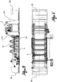
figures 1 and5 respectively show a schematic diagram of the method according to the present invention and a schematic diagram of the selective separation of the concentrated acid solution, according to possible embodiments; -
figures 2 ,3 and 4 respectively show a perspective view, a cross-section lateral view and a view from above, of a part of the etching plant according to the present invention, according to one variant. - . In the aforesaid figures, identical reference numerals will indicate identical or corresponding parts.
- . In particular the explanation of the method which follows will be made with reference to the reference numerals of the corresponding means of the
plant 1 with which a given step is performed. So, merely by way of example, reference numeral 4 refers both to the step of washing the primary surface and to the removal bath in which such step is performed. - . The present etching method which, as said, is used to increase the surface adhesion of a
fluoropolymer substrate 10, comprises a first step of feeding 22 such fluoropolymer substrate in the form of a continuous ribbon or film along a feeding direction X, where such substrate defines at least aprimary surface 12. Preferably, such substrate is a substrate in polytetrafluoroethylene (PTFE). Further embodiments foresee that the fluoropolymer is selected from the group consisting in PTFE, fluorinated ethylene propylene (FEP), perfluoroalkoxy (PFA), polyvinylidene fluoride (PVDF) - or the like - and mixtures thereof. - . Consequently, the present method is a (semi)-continuous etching method, which is performed at least on the primary surface which is thus the surface which at the end of the steps discussed below will prove to have improved surface adhesion.
- . Within the present description the term "etching" is understood to mean a chemical process suitable for making the fluoropolymer substrate suitable for gluing to other surfaces, by improving its adhesive properties.
- . In addition, within the present invention the term "feed direction X" is understood to mean directions of supplying the substrate not necessarily rectilinear, though some variants may provide for such. However, such term will also and above all be understood as a direction roughly parallel to the main extension of the fluoropolymer ribbon or film having a "complex" pattern, that is to say a succession of loops, curves, straight sections etc.
- . According to a shown embodiment, the entire continuous fluoropolymer ribbon or film is subjected to etching, so that in such case not only the
primary surface 12 but also anopposite surface 32 delimiting the thickness the ribbon or film will undergo such treatment. Equally, aconnection surface 36 connectingsuch surfaces - . In other words, one embodiment provides that the entire substrate is immersed in or at least wetted by the adhesion-promoting solution.
- . In a further step, at least a part of the
primary surface 12 is subjected to one ormore etching operations 2 by means of an adhesion-promoting solution comprising a complex of an alkali metal in naphthalene. Such surface treatments of fluoropolymer surfaces, suitable for semiconductor production, are known (see for exampleUS 5 859 086 A ). - . Consequently, such step is essential for the fluoropolymer substrate to adhere firmly to various types of supports, varied according to the desired application, and provides for the partial removal of the atoms of fluorine ("defluorination") from one of the aforesaid surfaces of the substrate.
- . Preferably the alkali metal used is sodium, in as much as deemed by the authors of the present invention as one of the most reliable chemical abrasives of fluoropolymers. Further embodiments may provide for the use of lithium, potassium or mixtures thereof, (including mixtures of the same with sodium).
- . According to one advantageous embodiment, the adhesion-promoting solution is produced by means of a solubilisation/
reaction 20, 20' which is preferably performed in situ, between diethylene glycol dimethyl ether, the alkali metal and the naphthalene. - . The advantages related to the use of diethylene glycol dimethyl ether, are the high level of stability at ambient temperatures (and even slightly over ambient temperatures), the reduced inflammability with a flash point of approximately 57°C, and the viscosity similar to that of water which it gives to the adhesion-promoting solution, such latter being a significant technological advantage. Added to this is a sufficient propensity of such mixture to "wet" the surfaces of the fluoropolymer substrate.
- . In yet a further step of the present method the part of the
primary surface 12 wetted by the adhesion-promoting solution is washed 4 by means of awashing solution 42 comprising aqueous acetic acid or aqueous formic acid. - . This way, all the residues of the adhesion-promoting solution are removed from the primary solution and the etching process is thus stopped. Optionally, subsequent to the washing step 4, a step of winding 34 the continuous ribbon or film of
fluoropolymer substrate 10 in one or more collection bobbins is provided for, which can thus be stored. - . According to a further preferred embodiment, the step of washing with the
washing solution 42 may be preceded by a first step of pre-washing 14 in an organic phase (comprising or consisting for example of diethylene glycol dimethyl ether), and of a second step of pre-washing 16 in an aqueous phase with water at a temperature above ambient temperature. - . Consequently, at the end of the washing and the optional pre-washings, the removal of the adhesion-promoting solution proves virtually to be complete.
- . According to a particularly advantageous embodiment, the organic phase may be purified, for example distilled 18, and may be re-introduced in the
first pre-washing step 14. - . According to a particularly advantageous variant, the washing step may be followed by a step of drying the continuous ribbon or film of
fluoropolymer substrate 10, for example at a temperature of approximately 50°C - 100°C, preferably of approximately 60° - 80°C. To such purpose, downstream of the removal bath 4 discussed below a drying oven could be provided. - . In yet a further step of the method, a
concentrated solution 24 of acetic acid, or of formic acid for some variants, is selectively separated from thewashing solution 42 by means ofinverse osmosis operations US 2008/277342 . - . In other words, the separation step foresees a previous operation of inverse osmosis 6 (at a first pressure P1) and a subsequent operation of inverse osmosis 8 (at a second pressure P2), wherein said latter operation takes place at a higher pressure than the pressure P1 (P2 > P1 or P >>P1). For example, the second pressure P2 may be approximately 2-10 times the first pressure P1 used in the
previous operation 6. - . In a preferred variant of the method, the separation step comprises a first (or previous) 6 and a second (or subsequent) 8 operation of inverse osmosis, the second operation being conducted on a
concentrated fraction 44 coming from the first operation. To such purpose, reference is made for example to the schematic diagram infigure 5 . - . For example, since the first
concentrated fraction 44 proceeds towards the second inverse osmosis operation leaving a first permeatedfraction 46 from the firstinverse osmosis operation 6, such permeatedfraction 46 may be subjected to one or more steps selected from the group consisting in oxidation, bacterial oxidation, ultrafiltration, immersed membrane ultrafiltration, reuse and/or drainage, despite the last being the least preferred of the embodiments. - . In an advantageous variant of the method, a second permeated
fraction 48 of the secondinverse osmosis operation 8 forms theconcentrated solution 24 of acetic acid or of formic acid. - . In fact, the presence of an increased pressure in the
second operation 8 causes an enrichment of acetic acid (or formic acid) in the second permeatedfraction 48, since the latter has a titre substantially corresponding to theconcentrated solution 24. - . Optionally, the second permeated
fraction 48 could have an acid concentration even higher than that needed for thewashing solution 42. In such case, it could be preferable to dilute the concentrated acid solution, for example by means of the water used in thesecond pre-washing step 16. - . Consequently, the method according to the present invention further comprises a step of introducing at least a portion of the concentrated solution of
acetic acid 24 or of formic acid in thewashing solution 42 to thus create a recirculation. - . This way, it is in fact possible to avoid a tout court disposal of such acid in the external environment for example in a water course. In addition, such method virtually eliminates the need to use "fresh" acetic acid or formic acid for the continuation of the (semi-)continuous method.
- . In other words, since the purification yields of the
washing solution 42 are extremely high (2-3% of residual polluted waters to be sent for disposal), with the method and plant discussed the use of new materials can be drastically limited. Advantages of a productive and environmental nature ensue. - . The present invention further relates to a (semi-)
continuous etching plant 1 for increasing the surface adhesion of afluoropolymer substrate 10. Preferably, such plant has proved particularly suitable for implementing the method just discussed above so that, even where not expressly specified, such plant provides for all the technical means needed to conduct any of the previous steps of the method. - . The
plant 1 comprises feeding means 22 of thefluoropolymer substrate 10 in the form of a continuous ribbon or film along a feeding direction X, said substrate delimiting theprimary surface 12 and preferably theopposite surface 32 - . As shown for example schematically in
figure 2 , the feeding means 22 comprise one or more feed bobbins, from which the fluoropolymer substrate is progressively unwound in the direction X. According to a further embodiment (not shown), the feeding means may comprise a production plant of the substrate in fluoropolymer. Consequently, in such variant, the winding of the aforesaid substrate onto bobbins becomes superfluous, in that the plant according to the present invention may be positioned directly downstream of a fluoropolymer production plant. - . Within the present description, the terms "upstream" and "downstream" are understood to mean the apparatus positioned respectively before or after the appliances specified in relation to the feed direction X, or in relation to the flow direction of the specified process fluids.
- . The
plant 1 further foresees one ormore etching tanks 2 containing the adhesion-promoting solution comprising the complex of the alkali metal in naphthalene for the chemical attack of at least a part of theprimary surface 12. This way the etching at least of such surface takes place. - . Consequently, the fluoropolymer ribbon or film may be immersed in said
tank 2, or may lick the free surface of the tank so that only one surface undergoes the chemical attack. Optionally, in order to wet the primary surface with the adhesion-promoting solution the system disclosed in the publicationUS4637856 could be used. - . According to an advantageous variant, the
plant 1 comprises a plurality of return calenders 28, 28' for thecontinuous fluoropolymer substrate 10, positioned and distanced along the feed direction X to immerse thesubstrate 10 in the adhesion-promoting solution and/or in the washing solution, and optionally in the organic phase and/or aqueous phase. - . According to a particularly advantageous variant, the
plant 1 comprises at least onesynthesis reactor 20, 20' in which the washing solution is produced by means of an in situ reaction between diethylene glycol dimethyl ether, the alkali metal and the naphthalene. Such reactor is preferably fluidically connected to theetching tank 2 or to the plurality thereof. For example, as shown schematically in the diagram infigure 1 , a pair ofsynthesis reactors 20, 20' positioned parallel to each other may be provided. - . The
plant 1 further comprises a removal bath 4 of the adhesion-promoting solution from the part of theprimary surface 12 wetted by said solution, wherein the removal bath contains the washing solution comprising aqueous acetic acid or aqueous formic acid. - . According to one embodiment, downstream of the removal bath 4, the plant comprises at least one
collection bobbin 34 of the fluoropolymer substrate of increased surface adhesion. - . According to a further embodiment, upstream of the removal bath 4 of the adhesion-promoting solution, the
plant 1 may comprise afirst pre-washing bath 14 in the organic phase (in particular comprising diethylene glycol dimethyl ether), and asecond pre-washing bath 16 in the aqueous phase, for example containing water at a temperature above ambient temperature. - . For the variants providing for the
first pre-washing bath 14, distillation means 18 of the organic phase may also be provided, fluidically communicating with saidfirst pre-washing bath 14 so as to create a secondary recirculation. - . This way, the organic phase could be withdrawn from the first bath 14 (via the
line 38 infigure 1 ), and re-emitted (line 40) following an at least partial purification in saidfirst pre-washing bath 14 in a preferably (semi-)continuous manner. - . The
plant 1 further comprisesinverse osmosis stations concentrated solution 24 of acetic acid or of formic acid from the washing solution. - . To such purpose, at least one inverse osmosis station (6 or 8 but preferably both
stations 6, 8) preferably comprises a multi-layer separation membrane comprising a non-woven support layer, an intermediate micro-porous layer, and a protective layer of the intermediate layer. - . Given that the support layer gives good dimensional stability but an unsatisfactory separation ability of the acetic acid, and given the aggressive ambient in which the membrane finds itself operating in, the association of the aforesaid layers has proved surprisingly effective in isolating the concentrated acid solution.
- . According to a preferred embodiment, the support layer comprises polyester, the intermediate layer is polysulfonic and the protective layer is a coating applied to the intermediate layer. In particular the protective layer has a thickness of approximately 2500 Ångstrom (250 nm) or less, and preferably of approximately 2000 Ångstrom (200 nm). For example, one possible membrane which could be used in the aforesaid inverse osmosis station is made by "The Dow Chemical Company" under the brand name "Filmtec® FT30 Membrane".
- . The
plant 1 further comprises means for re-introducing 26 at least a portion of theconcentrated solution 24 of acetic acid or formic acid in the washing solution to form a recirculation. - . This way, as said, a considerable quantity of acid can be recovered from the used washing solution (that is to say containing a quantity no longer acceptable of adhesion-promoting solution or of the single components thereof), so as to re-introduce it in the removal bath 4.
- . According to a particularly advantageous embodiment, a first 6 and a second 8 inverse osmosis station are respectively positioned upstream and downstream of a
second collection environment 30, configured to receive a firstconcentrated fraction 44 from the firstinverse osmosis station 6, and to send to the removal bath 4 a second permeatedfraction 48 of the secondinverse osmosis operation 8 which forms theconcentrated solution 24 of acetic acid or of formic acid. - . In other words, the
second collection environment 30 creates an intermediate storage area to compensate any deficits (or excesses) which might occur in the mass balance between the flow entering the firstconcentrated fraction 44 and the flow coming out of the second permeatedfraction 48. - . However, as regards the second permeated
fraction 50 generated by the secondinverse osmosis operation 8, such fraction is preferably drained by the plant, and for example sent for special disposal outside said plant. For example, such permeatedfraction 50 may be collected in adedicated drainage environment 64. - . Optionally, between the removal bath 4 and the second collection environment 30 a
first collection environment 62 may be provided which receives, on a transitory basis, the used washing solution coming from the removal bath and from which the firstinverse osmosis station 6 withdraws such solution. - . The purpose of the present invention will now be illustrated on the basis of several non-limiting examples.
- . In a reactor holding 200 litres, at a temperature of 50 - 60°C and subject to constant stirring, a first quantity of diethylene glycol dimethyl ether (technical titre) amounting to approximately 80 - 180 kg (for example 100 - 150 kg), and a second quantity of sodium naphthalene of approximately 5 - 50 kg (for example 15 - 35 kg) with a ratio of sodium-naphthalene of 1:1 or 2:1 are mixed together. Such variability of weight is due mainly to the etching quality or target to be achieved. The mixture is made to react for a time of approximately 1 - 6 hours or 2 - 4 hours, and is subsequently fed to the etching tank or to the plurality thereof.
- . The washing solution is made by mixing in approximately 100 litres of water, a volume of acetic acid at 99.9% until a pH of the solution of approximately 2 - 6, preferably 3 - 5, for example approximately 4, is reached.
- . The initial concentration of acetic acid in the removal bath, before start washing of the primary surface, is substantially the same that can be achieved at the end of the second inverse osmosis stage when the plant is operational.
- . Innovatively, the plant and method according to the present invention are suitable to prevent mere drainage of the washing waters containing acetic and other acids, any contaminants deriving from the etching process in the external environment, and drastically reduce the use of water and fresh acid.
- . In fact, advantageously, the plant and method according to the present invention allow consistent savings in water consumption. In particular an average consumption of water in traditional plants was to the order of 50 - 80 m3/day. However, by means of the present invention, such volume can be reduced to approximately 0.5 - 1.5 m3/day, with a total annual saving of 12,000 - 20,000 m3 of water.
- . Advantageously, the plant and method described make it possible to re-use other process fluids, with a consequent benefit in productive and environmental terms.
- . Advantageously, the plant and method described have been specially designed for the etching of the fluoropolymer, and the separation appliances have been optimised specifically for such purpose.
- . Advantageously, the plant and method according to the present invention make it possible to achieve efficient production cycles which, by virtue of the constructive simplicity described above permit a desirable improvement to be achieved compared to the etching methods of the prior art.
- . Even if not previously specified, a person skilled in the art may make variations to any of the aforementioned aspects, replacing them with others technically equivalent, resorting to the expertise typical of the sector.
- . These variations or replacements are also contained within the sphere of protection defined by the following claims.
- . In addition, any alternatives illustrated in relation to a particular embodiment may be realised independently of the other variants described.
Claims (15)
- (Semi-)continuous etching method for increasing the surface adhesion of a fluoropolymer substrate (10) comprising, in sequence, the steps of:- feeding (22) a fluoropolymer substrate (10) in the form of continuous ribbon or film along a feeding direction (X), said substrate defining a primary surface (12);- subjecting to one or more etching operations (2) at least a part of the primary surface (12) by means of an adhesion-promoting solution comprising a complex of an alkali metal, such as sodium, in naphthalene;- washing (4) the part of the primary surface (12) wetted by the adhesion-promoting solution by means of a washing solution (42) comprising aqueous acetic acid or formic acid;- selectively separating a concentrated solution (24) of acetic acid or of formic acid from the washing solution (42) by means of inverse osmosis operations (6, 8) at increasing pressure;- re-introducing at least a portion of the concentrated solution (24) of acetic acid or of formic acid in the washing solution (42) to create a recirculation.
- Method according to claim 1, wherein a subsequent operation of inverse osmosis (8) takes place at a pressure 2-10 times the pressure of a previous operation (6).
- Method according to claim 1 or 2, wherein the separation step comprises a first (6) and a second (8) operation of inverse osmosis, the second operation being conducted on a first concentrated fraction (44) coming from the first operation.
- Method according to claim 3, wherein a first permeated fraction (46) of the first inverse osmosis operation (6) is subjected to one or more steps selected from the group consisting in oxidation, bacterial oxidation, ultrafiltration, immersed membrane ultrafiltration, reuse and /or drainage.
- Method according to claim 3 or 4, wherein a second permeated fraction (48) of the second inverse osmosis operation (8) forms the concentrated solution (24) of acetic acid or of formic acid.
- Method according to any of the previous claims, wherein the step of washing (4) with the washing solution (42) is preceded by a first step of pre-washing (14) in an organic phase comprising diethylene glycol dimethyl ether, and by a second step of pre-washing (16) in an aqueous phase, for example with water at a temperature above ambient temperature, wherein said organic phase may optionally be purified by means of distillation (18) and re-introduced in the first pre-washing step (14).
- Method according to any of the previous claims, wherein the adhesion-promoting solution is produced by means of a reaction in situ (20, 20') between diethylene glycol dimethyl ether, the alkali metal and naphthalene.
- (Semi-)continuous etching plant (1) for increasing the surface adhesion of a fluoropolymer substrate (10) comprising:- feeding means (22) of the fluoropolymer substrate (10) in the form of a continuous ribbon or film along a feeding direction (X), said substrate defining a primary surface (12);- one or more etching tanks (2) containing an adhesion-promoting solution comprising a complex of an alkali metal in naphthalene for the chemical etching of at least a part of the primary surface (12);- a removal bath (4) of the adhesion-promoting solution from the part of the primary surface (12) wetted by said solution, said removal bath containing a washing solution (42) comprising aqueous acetic acid or aqueous formic acid;- inverse osmosis stations (6, 8) working at increasing pressure, configured to selectively separate a concentrated solution (24) of acetic acid or of formic acid from the washing solution (42);- means for re-introducing (26) at least a portion of the concentrated solution (24) of acetic acid or of formic acid in the washing solution (42) to create a recirculation.
- Plant according to claim 8, wherein at least one inverse osmosis station (6; 8) comprises a multi-layer separation membrane comprising a non-woven support layer, an intermediate micro-porous layer, and a protective layer of the intermediate layer, wherein the support layer preferably comprises polyester, the intermediate layer is preferably polysulfonic and wherein the protective layer is optionally a coating, preferably having a thickness of approximately 2500 Ångstrom (250 nm) or less, applied to the intermediate layer.
- Plant according to any of the claims 8-9, wherein a first (6) and a second (8) inverse osmosis stations are respectively positioned upstream and downstream of a second collection environment (30), configured to receive a first concentrated fraction (44) from the first inverse osmosis station (6), and to send to the removal bath (4) a second permeated fraction (48) of the second inverse osmosis operation (8) which forms the concentrated solution (24) of acetic acid or of formic acid.
- Plant according to any of the claims 8-10, comprising, upstream of the removal bath (4) of the adhesion-promoting solution, a first pre-washing bath (14) in an organic phase comprising diethylene glycol dimethyl ether, and a second pre-washing bath (16) in an aqueous phase, for example containing water at a temperature above ambient temperature.
- Plant according to any of the claims 8-11, optionally when dependent on claim 11, comprising a plurality of return calenders (28, 28') of the continuous fluoropolymer substrate (10), positioned along the feed direction (X) to immerse said substrate (10) in the adhesion-promoting solution and/or in the washing solution (42), and optionally in the organic phase and/or aqueous phase.
- Plant according to claim 11 or 12, comprising distillation means (18) of the organic phase, fluidically communicating with the first pre-washing bath (14) so as to create a secondary recirculation.
- Plant according to any of the claims 8-13, comprising at least one synthesis reactor (20, 20') wherein the adhesion-promoting solution is produced by means of a reaction in situ between diethylene glycol dimethyl ether, alkali metal and naphthalene, said reactor being fluidically connected to the etching tank (2) or to the plurality thereof.
- Method according to claim 1, or plant according to claim 8, wherein the fluoropolymer is selected from the group consisting in fluorinated ethylene propylene, perfluoroalkoxy, polyvinylidene fluoride and mixtures thereof.
Applications Claiming Priority (1)
| Application Number | Priority Date | Filing Date | Title |
|---|---|---|---|
| PCT/IT2013/000280 WO2015052736A1 (en) | 2013-10-10 | 2013-10-10 | Method and plant for etching a fluoropolymer substrate |
Publications (2)
| Publication Number | Publication Date |
|---|---|
| EP3016997A1 EP3016997A1 (en) | 2016-05-11 |
| EP3016997B1 true EP3016997B1 (en) | 2017-06-21 |
Family
ID=49911766
Family Applications (1)
| Application Number | Title | Priority Date | Filing Date |
|---|---|---|---|
| EP13815590.8A Active EP3016997B1 (en) | 2013-10-10 | 2013-10-10 | Method and plant for etching a fluoropolymer substrate |
Country Status (4)
| Country | Link |
|---|---|
| US (1) | US9481773B2 (en) |
| EP (1) | EP3016997B1 (en) |
| CN (1) | CN105026470B (en) |
| WO (1) | WO2015052736A1 (en) |
Families Citing this family (2)
| Publication number | Priority date | Publication date | Assignee | Title |
|---|---|---|---|---|
| CN115042459A (en) * | 2022-07-20 | 2022-09-13 | 上海翊科聚合物科技有限公司 | A continuous etching system for PTFE tubes |
| CN120096073B (en) * | 2025-05-12 | 2025-07-18 | 海生医疗科技(宁波)有限公司 | PTFE tube continuous etching equipment and continuous etching method |
Family Cites Families (6)
| Publication number | Priority date | Publication date | Assignee | Title |
|---|---|---|---|---|
| US4637856A (en) * | 1985-12-12 | 1987-01-20 | Dixon Industries Corporation | Apparatus and process for etching fluoroplastics |
| US5635071A (en) * | 1995-01-20 | 1997-06-03 | Zenon Airport Enviromental, Inc. | Recovery of carboxylic acids from chemical plant effluents |
| US5859086A (en) * | 1996-08-07 | 1999-01-12 | Competitive Technologies Of Pa, Inc. | Light directed modification fluoropolymers |
| US6077913A (en) * | 1998-03-26 | 2000-06-20 | Beholz Technology, L.L.C. | Process for producing paintable polymeric articles |
| US8092918B2 (en) * | 2005-08-16 | 2012-01-10 | Ge Osmonics, Inc. | Polyamide matrices and methods for their preparation and use |
| CN102199306B (en) * | 2011-05-12 | 2013-01-30 | 苏州斯迪克新材料科技股份有限公司 | Membrane for sealing bag on inner wall of large airplane and surface treatment method thereof |
-
2013
- 2013-10-10 US US15/022,150 patent/US9481773B2/en active Active
- 2013-10-10 CN CN201380024837.3A patent/CN105026470B/en active Active
- 2013-10-10 WO PCT/IT2013/000280 patent/WO2015052736A1/en not_active Ceased
- 2013-10-10 EP EP13815590.8A patent/EP3016997B1/en active Active
Also Published As
| Publication number | Publication date |
|---|---|
| CN105026470A (en) | 2015-11-04 |
| EP3016997A1 (en) | 2016-05-11 |
| WO2015052736A1 (en) | 2015-04-16 |
| US9481773B2 (en) | 2016-11-01 |
| US20160237231A1 (en) | 2016-08-18 |
| CN105026470B (en) | 2018-06-29 |
Similar Documents
| Publication | Publication Date | Title |
|---|---|---|
| JP5419446B2 (en) | Method for preparing chlorohydrin in a corrosion resistant apparatus | |
| JP2012502079A (en) | Method for producing chlorohydrin, epoxide, diol, diol derivative or epoxy derivative | |
| CN101767847B (en) | A method for purification and recovery of acid waste liquid based on membrane technology | |
| CN101208323A (en) | Process for the preparation of epoxides from polyhydroxyaliphatic hydrocarbons and chlorinating agents | |
| KR101167393B1 (en) | Filter wash for chloralkali process | |
| WO2010029153A1 (en) | Process for purifying hydrogen chloride | |
| JP6145909B2 (en) | Electrodeposition paint recovery system and method | |
| CN102161548A (en) | Method for recycling and treating electroplating wastewater and equipment thereof | |
| US9481773B2 (en) | Method and plant for etching a fluoropolymer substrate | |
| CN104645651A (en) | Flexible method for the treatment of a solvent, such as monoethylene glycol, used in the extraction of natural gas | |
| US20150053601A1 (en) | Membrane module and process for producing same | |
| CN108358356A (en) | A method of it recycling copper from cupric brown oxide waste liquid and recycles sulfuric acid | |
| KR20090116730A (en) | Waste solution treatment method | |
| Abejón et al. | Ultrapurification of hydrogen peroxide solution from ionic metals impurities to semiconductor grade by reverse osmosis | |
| JP6267313B2 (en) | Method for producing dichloropropanol | |
| JP2009528917A (en) | Method of distillatively removing dinitrotoluene in process wastewater from the process of producing dinitrotoluene by nitrating toluene with nitration acid | |
| CN105461131A (en) | Electroplating rinse water concentrate treatment method | |
| JP5245626B2 (en) | Method and apparatus for recovering water-soluble organic solvent having amino group | |
| JP6923668B2 (en) | Acid-resistant nanoseparation membrane with improved flow rate and its manufacturing method | |
| JP2016078014A (en) | Treatment method and treatment device for ammonia-containing waste water | |
| CN103657425A (en) | Method for recycling waste polyamide roll type reverse-osmosis membrane elements | |
| CN105683092B (en) | For carrying out IPA concentration and the compound membrane separating method of wastewater treatment to the waste water containing IPA | |
| CN102070217A (en) | Treatment and reuse method of pure terephthalic acid production wastewater | |
| JP2010074109A (en) | Cleaning system | |
| TWI405050B (en) | Process for recovering and purifying tetraalkyl ammonium hydroxide from waste solution containing the same |
Legal Events
| Date | Code | Title | Description |
|---|---|---|---|
| PUAI | Public reference made under article 153(3) epc to a published international application that has entered the european phase |
Free format text: ORIGINAL CODE: 0009012 |
|
| 17P | Request for examination filed |
Effective date: 20151223 |
|
| AK | Designated contracting states |
Kind code of ref document: A1 Designated state(s): AL AT BE BG CH CY CZ DE DK EE ES FI FR GB GR HR HU IE IS IT LI LT LU LV MC MK MT NL NO PL PT RO RS SE SI SK SM TR |
|
| AX | Request for extension of the european patent |
Extension state: BA ME |
|
| GRAP | Despatch of communication of intention to grant a patent |
Free format text: ORIGINAL CODE: EPIDOSNIGR1 |
|
| DAX | Request for extension of the european patent (deleted) | ||
| INTG | Intention to grant announced |
Effective date: 20161221 |
|
| GRAS | Grant fee paid |
Free format text: ORIGINAL CODE: EPIDOSNIGR3 |
|
| GRAA | (expected) grant |
Free format text: ORIGINAL CODE: 0009210 |
|
| AK | Designated contracting states |
Kind code of ref document: B1 Designated state(s): AL AT BE BG CH CY CZ DE DK EE ES FI FR GB GR HR HU IE IS IT LI LT LU LV MC MK MT NL NO PL PT RO RS SE SI SK SM TR |
|
| RAP1 | Party data changed (applicant data changed or rights of an application transferred) |
Owner name: MAFLON S.P.A. |
|
| REG | Reference to a national code |
Ref country code: GB Ref legal event code: FG4D |
|
| REG | Reference to a national code |
Ref country code: CH Ref legal event code: EP |
|
| REG | Reference to a national code |
Ref country code: IE Ref legal event code: FG4D |
|
| REG | Reference to a national code |
Ref country code: AT Ref legal event code: REF Ref document number: 902899 Country of ref document: AT Kind code of ref document: T Effective date: 20170715 |
|
| REG | Reference to a national code |
Ref country code: DE Ref legal event code: R096 Ref document number: 602013022654 Country of ref document: DE |
|
| REG | Reference to a national code |
Ref country code: NL Ref legal event code: MP Effective date: 20170621 |
|
| PG25 | Lapsed in a contracting state [announced via postgrant information from national office to epo] |
Ref country code: NO Free format text: LAPSE BECAUSE OF FAILURE TO SUBMIT A TRANSLATION OF THE DESCRIPTION OR TO PAY THE FEE WITHIN THE PRESCRIBED TIME-LIMIT Effective date: 20170921 Ref country code: FI Free format text: LAPSE BECAUSE OF FAILURE TO SUBMIT A TRANSLATION OF THE DESCRIPTION OR TO PAY THE FEE WITHIN THE PRESCRIBED TIME-LIMIT Effective date: 20170621 Ref country code: LT Free format text: LAPSE BECAUSE OF FAILURE TO SUBMIT A TRANSLATION OF THE DESCRIPTION OR TO PAY THE FEE WITHIN THE PRESCRIBED TIME-LIMIT Effective date: 20170621 Ref country code: GR Free format text: LAPSE BECAUSE OF FAILURE TO SUBMIT A TRANSLATION OF THE DESCRIPTION OR TO PAY THE FEE WITHIN THE PRESCRIBED TIME-LIMIT Effective date: 20170922 Ref country code: HR Free format text: LAPSE BECAUSE OF FAILURE TO SUBMIT A TRANSLATION OF THE DESCRIPTION OR TO PAY THE FEE WITHIN THE PRESCRIBED TIME-LIMIT Effective date: 20170621 |
|
| REG | Reference to a national code |
Ref country code: FR Ref legal event code: PLFP Year of fee payment: 5 |
|
| REG | Reference to a national code |
Ref country code: LT Ref legal event code: MG4D |
|
| REG | Reference to a national code |
Ref country code: AT Ref legal event code: MK05 Ref document number: 902899 Country of ref document: AT Kind code of ref document: T Effective date: 20170621 |
|
| PG25 | Lapsed in a contracting state [announced via postgrant information from national office to epo] |
Ref country code: RS Free format text: LAPSE BECAUSE OF FAILURE TO SUBMIT A TRANSLATION OF THE DESCRIPTION OR TO PAY THE FEE WITHIN THE PRESCRIBED TIME-LIMIT Effective date: 20170621 Ref country code: LV Free format text: LAPSE BECAUSE OF FAILURE TO SUBMIT A TRANSLATION OF THE DESCRIPTION OR TO PAY THE FEE WITHIN THE PRESCRIBED TIME-LIMIT Effective date: 20170621 Ref country code: BG Free format text: LAPSE BECAUSE OF FAILURE TO SUBMIT A TRANSLATION OF THE DESCRIPTION OR TO PAY THE FEE WITHIN THE PRESCRIBED TIME-LIMIT Effective date: 20170921 Ref country code: NL Free format text: LAPSE BECAUSE OF FAILURE TO SUBMIT A TRANSLATION OF THE DESCRIPTION OR TO PAY THE FEE WITHIN THE PRESCRIBED TIME-LIMIT Effective date: 20170621 Ref country code: SE Free format text: LAPSE BECAUSE OF FAILURE TO SUBMIT A TRANSLATION OF THE DESCRIPTION OR TO PAY THE FEE WITHIN THE PRESCRIBED TIME-LIMIT Effective date: 20170621 |
|
| PG25 | Lapsed in a contracting state [announced via postgrant information from national office to epo] |
Ref country code: CZ Free format text: LAPSE BECAUSE OF FAILURE TO SUBMIT A TRANSLATION OF THE DESCRIPTION OR TO PAY THE FEE WITHIN THE PRESCRIBED TIME-LIMIT Effective date: 20170621 Ref country code: SK Free format text: LAPSE BECAUSE OF FAILURE TO SUBMIT A TRANSLATION OF THE DESCRIPTION OR TO PAY THE FEE WITHIN THE PRESCRIBED TIME-LIMIT Effective date: 20170621 Ref country code: EE Free format text: LAPSE BECAUSE OF FAILURE TO SUBMIT A TRANSLATION OF THE DESCRIPTION OR TO PAY THE FEE WITHIN THE PRESCRIBED TIME-LIMIT Effective date: 20170621 Ref country code: AT Free format text: LAPSE BECAUSE OF FAILURE TO SUBMIT A TRANSLATION OF THE DESCRIPTION OR TO PAY THE FEE WITHIN THE PRESCRIBED TIME-LIMIT Effective date: 20170621 Ref country code: RO Free format text: LAPSE BECAUSE OF FAILURE TO SUBMIT A TRANSLATION OF THE DESCRIPTION OR TO PAY THE FEE WITHIN THE PRESCRIBED TIME-LIMIT Effective date: 20170621 |
|
| PG25 | Lapsed in a contracting state [announced via postgrant information from national office to epo] |
Ref country code: PL Free format text: LAPSE BECAUSE OF FAILURE TO SUBMIT A TRANSLATION OF THE DESCRIPTION OR TO PAY THE FEE WITHIN THE PRESCRIBED TIME-LIMIT Effective date: 20170621 Ref country code: ES Free format text: LAPSE BECAUSE OF FAILURE TO SUBMIT A TRANSLATION OF THE DESCRIPTION OR TO PAY THE FEE WITHIN THE PRESCRIBED TIME-LIMIT Effective date: 20170621 Ref country code: IS Free format text: LAPSE BECAUSE OF FAILURE TO SUBMIT A TRANSLATION OF THE DESCRIPTION OR TO PAY THE FEE WITHIN THE PRESCRIBED TIME-LIMIT Effective date: 20171021 Ref country code: SM Free format text: LAPSE BECAUSE OF FAILURE TO SUBMIT A TRANSLATION OF THE DESCRIPTION OR TO PAY THE FEE WITHIN THE PRESCRIBED TIME-LIMIT Effective date: 20170621 |
|
| REG | Reference to a national code |
Ref country code: DE Ref legal event code: R097 Ref document number: 602013022654 Country of ref document: DE |
|
| PLBE | No opposition filed within time limit |
Free format text: ORIGINAL CODE: 0009261 |
|
| STAA | Information on the status of an ep patent application or granted ep patent |
Free format text: STATUS: NO OPPOSITION FILED WITHIN TIME LIMIT |
|
| PG25 | Lapsed in a contracting state [announced via postgrant information from national office to epo] |
Ref country code: DK Free format text: LAPSE BECAUSE OF FAILURE TO SUBMIT A TRANSLATION OF THE DESCRIPTION OR TO PAY THE FEE WITHIN THE PRESCRIBED TIME-LIMIT Effective date: 20170621 |
|
| 26N | No opposition filed |
Effective date: 20180322 |
|
| PG25 | Lapsed in a contracting state [announced via postgrant information from national office to epo] |
Ref country code: MC Free format text: LAPSE BECAUSE OF FAILURE TO SUBMIT A TRANSLATION OF THE DESCRIPTION OR TO PAY THE FEE WITHIN THE PRESCRIBED TIME-LIMIT Effective date: 20170621 |
|
| REG | Reference to a national code |
Ref country code: CH Ref legal event code: PL |
|
| PG25 | Lapsed in a contracting state [announced via postgrant information from national office to epo] |
Ref country code: CH Free format text: LAPSE BECAUSE OF NON-PAYMENT OF DUE FEES Effective date: 20171031 Ref country code: LU Free format text: LAPSE BECAUSE OF NON-PAYMENT OF DUE FEES Effective date: 20171010 Ref country code: LI Free format text: LAPSE BECAUSE OF NON-PAYMENT OF DUE FEES Effective date: 20171031 |
|
| REG | Reference to a national code |
Ref country code: BE Ref legal event code: MM Effective date: 20171031 |
|
| PG25 | Lapsed in a contracting state [announced via postgrant information from national office to epo] |
Ref country code: BE Free format text: LAPSE BECAUSE OF NON-PAYMENT OF DUE FEES Effective date: 20171031 Ref country code: SI Free format text: LAPSE BECAUSE OF FAILURE TO SUBMIT A TRANSLATION OF THE DESCRIPTION OR TO PAY THE FEE WITHIN THE PRESCRIBED TIME-LIMIT Effective date: 20170621 |
|
| PG25 | Lapsed in a contracting state [announced via postgrant information from national office to epo] |
Ref country code: MT Free format text: LAPSE BECAUSE OF NON-PAYMENT OF DUE FEES Effective date: 20171010 |
|
| REG | Reference to a national code |
Ref country code: FR Ref legal event code: PLFP Year of fee payment: 6 |
|
| PG25 | Lapsed in a contracting state [announced via postgrant information from national office to epo] |
Ref country code: HU Free format text: LAPSE BECAUSE OF FAILURE TO SUBMIT A TRANSLATION OF THE DESCRIPTION OR TO PAY THE FEE WITHIN THE PRESCRIBED TIME-LIMIT; INVALID AB INITIO Effective date: 20131010 |
|
| PG25 | Lapsed in a contracting state [announced via postgrant information from national office to epo] |
Ref country code: CY Free format text: LAPSE BECAUSE OF FAILURE TO SUBMIT A TRANSLATION OF THE DESCRIPTION OR TO PAY THE FEE WITHIN THE PRESCRIBED TIME-LIMIT Effective date: 20170621 |
|
| PG25 | Lapsed in a contracting state [announced via postgrant information from national office to epo] |
Ref country code: MK Free format text: LAPSE BECAUSE OF FAILURE TO SUBMIT A TRANSLATION OF THE DESCRIPTION OR TO PAY THE FEE WITHIN THE PRESCRIBED TIME-LIMIT Effective date: 20170621 |
|
| PG25 | Lapsed in a contracting state [announced via postgrant information from national office to epo] |
Ref country code: TR Free format text: LAPSE BECAUSE OF FAILURE TO SUBMIT A TRANSLATION OF THE DESCRIPTION OR TO PAY THE FEE WITHIN THE PRESCRIBED TIME-LIMIT Effective date: 20170621 |
|
| PG25 | Lapsed in a contracting state [announced via postgrant information from national office to epo] |
Ref country code: PT Free format text: LAPSE BECAUSE OF FAILURE TO SUBMIT A TRANSLATION OF THE DESCRIPTION OR TO PAY THE FEE WITHIN THE PRESCRIBED TIME-LIMIT Effective date: 20170621 |
|
| PG25 | Lapsed in a contracting state [announced via postgrant information from national office to epo] |
Ref country code: AL Free format text: LAPSE BECAUSE OF FAILURE TO SUBMIT A TRANSLATION OF THE DESCRIPTION OR TO PAY THE FEE WITHIN THE PRESCRIBED TIME-LIMIT Effective date: 20170621 |
|
| REG | Reference to a national code |
Ref country code: DE Ref legal event code: R081 Ref document number: 602013022654 Country of ref document: DE Owner name: MAFLON S.P.A, IT Free format text: FORMER OWNER: MAFLON S.P.A., CASTELLI CALEPIO (BG), IT |
|
| P01 | Opt-out of the competence of the unified patent court (upc) registered |
Effective date: 20230420 |
|
| PGFP | Annual fee paid to national office [announced via postgrant information from national office to epo] |
Ref country code: DE Payment date: 20251028 Year of fee payment: 13 |
|
| PGFP | Annual fee paid to national office [announced via postgrant information from national office to epo] |
Ref country code: GB Payment date: 20251029 Year of fee payment: 13 |
|
| PGFP | Annual fee paid to national office [announced via postgrant information from national office to epo] |
Ref country code: IT Payment date: 20251030 Year of fee payment: 13 |
|
| PGFP | Annual fee paid to national office [announced via postgrant information from national office to epo] |
Ref country code: FR Payment date: 20251029 Year of fee payment: 13 |
|
| PGFP | Annual fee paid to national office [announced via postgrant information from national office to epo] |
Ref country code: IE Payment date: 20251013 Year of fee payment: 13 |