EP3016895B1 - Vehicle-actuated weather barrier apparatus - Google Patents
Vehicle-actuated weather barrier apparatus Download PDFInfo
- Publication number
- EP3016895B1 EP3016895B1 EP14739656.8A EP14739656A EP3016895B1 EP 3016895 B1 EP3016895 B1 EP 3016895B1 EP 14739656 A EP14739656 A EP 14739656A EP 3016895 B1 EP3016895 B1 EP 3016895B1
- Authority
- EP
- European Patent Office
- Prior art keywords
- vehicle
- seal
- weather barrier
- barrier apparatus
- doorway
- Prior art date
- Legal status (The legal status is an assumption and is not a legal conclusion. Google has not performed a legal analysis and makes no representation as to the accuracy of the status listed.)
- Active
Links
- 230000004888 barrier function Effects 0.000 title claims description 101
- 230000008878 coupling Effects 0.000 claims description 14
- 238000010168 coupling process Methods 0.000 claims description 14
- 238000005859 coupling reaction Methods 0.000 claims description 14
- 238000007789 sealing Methods 0.000 claims description 11
- 239000006260 foam Substances 0.000 description 12
- 239000012528 membrane Substances 0.000 description 9
- 239000004744 fabric Substances 0.000 description 7
- 230000007613 environmental effect Effects 0.000 description 6
- 239000000463 material Substances 0.000 description 6
- 238000000034 method Methods 0.000 description 6
- 238000006243 chemical reaction Methods 0.000 description 5
- 230000006835 compression Effects 0.000 description 5
- 238000007906 compression Methods 0.000 description 5
- 238000013459 approach Methods 0.000 description 3
- 238000005452 bending Methods 0.000 description 3
- 238000010586 diagram Methods 0.000 description 3
- 230000002093 peripheral effect Effects 0.000 description 3
- 230000000694 effects Effects 0.000 description 2
- 239000011152 fibreglass Substances 0.000 description 2
- 230000003116 impacting effect Effects 0.000 description 2
- 241000238631 Hexapoda Species 0.000 description 1
- 241001465754 Metazoa Species 0.000 description 1
- 230000001143 conditioned effect Effects 0.000 description 1
- 238000010276 construction Methods 0.000 description 1
- 239000000356 contaminant Substances 0.000 description 1
- 230000001419 dependent effect Effects 0.000 description 1
- 239000002184 metal Substances 0.000 description 1
- 230000003578 releasing effect Effects 0.000 description 1
- 125000000391 vinyl group Chemical group [H]C([*])=C([H])[H] 0.000 description 1
- 229920002554 vinyl polymer Polymers 0.000 description 1
- 239000002023 wood Substances 0.000 description 1
Images


Classifications
-
- E—FIXED CONSTRUCTIONS
- E04—BUILDING
- E04B—GENERAL BUILDING CONSTRUCTIONS; WALLS, e.g. PARTITIONS; ROOFS; FLOORS; CEILINGS; INSULATION OR OTHER PROTECTION OF BUILDINGS
- E04B1/00—Constructions in general; Structures which are not restricted either to walls, e.g. partitions, or floors or ceilings or roofs
- E04B1/343—Structures characterised by movable, separable, or collapsible parts, e.g. for transport
- E04B1/344—Structures characterised by movable, separable, or collapsible parts, e.g. for transport with hinged parts
-
- B—PERFORMING OPERATIONS; TRANSPORTING
- B65—CONVEYING; PACKING; STORING; HANDLING THIN OR FILAMENTARY MATERIAL
- B65G—TRANSPORT OR STORAGE DEVICES, e.g. CONVEYORS FOR LOADING OR TIPPING, SHOP CONVEYOR SYSTEMS OR PNEUMATIC TUBE CONVEYORS
- B65G69/00—Auxiliary measures taken, or devices used, in connection with loading or unloading
- B65G69/008—Dock- or bumper-seals
-
- B—PERFORMING OPERATIONS; TRANSPORTING
- B65—CONVEYING; PACKING; STORING; HANDLING THIN OR FILAMENTARY MATERIAL
- B65G—TRANSPORT OR STORAGE DEVICES, e.g. CONVEYORS FOR LOADING OR TIPPING, SHOP CONVEYOR SYSTEMS OR PNEUMATIC TUBE CONVEYORS
- B65G69/00—Auxiliary measures taken, or devices used, in connection with loading or unloading
- B65G69/28—Loading ramps; Loading docks
- B65G69/287—Constructional features of deck or surround
-
- E—FIXED CONSTRUCTIONS
- E04—BUILDING
- E04B—GENERAL BUILDING CONSTRUCTIONS; WALLS, e.g. PARTITIONS; ROOFS; FLOORS; CEILINGS; INSULATION OR OTHER PROTECTION OF BUILDINGS
- E04B1/00—Constructions in general; Structures which are not restricted either to walls, e.g. partitions, or floors or ceilings or roofs
- E04B1/343—Structures characterised by movable, separable, or collapsible parts, e.g. for transport
- E04B1/344—Structures characterised by movable, separable, or collapsible parts, e.g. for transport with hinged parts
- E04B1/3441—Structures characterised by movable, separable, or collapsible parts, e.g. for transport with hinged parts with articulated bar-shaped elements
-
- B—PERFORMING OPERATIONS; TRANSPORTING
- B65—CONVEYING; PACKING; STORING; HANDLING THIN OR FILAMENTARY MATERIAL
- B65G—TRANSPORT OR STORAGE DEVICES, e.g. CONVEYORS FOR LOADING OR TIPPING, SHOP CONVEYOR SYSTEMS OR PNEUMATIC TUBE CONVEYORS
- B65G69/00—Auxiliary measures taken, or devices used, in connection with loading or unloading
-
- E—FIXED CONSTRUCTIONS
- E04—BUILDING
- E04H—BUILDINGS OR LIKE STRUCTURES FOR PARTICULAR PURPOSES; SWIMMING OR SPLASH BATHS OR POOLS; MASTS; FENCING; TENTS OR CANOPIES, IN GENERAL
- E04H15/00—Tents or canopies, in general
- E04H15/20—Tents or canopies, in general inflatable, e.g. shaped, strengthened or supported by fluid pressure
-
- E—FIXED CONSTRUCTIONS
- E04—BUILDING
- E04H—BUILDINGS OR LIKE STRUCTURES FOR PARTICULAR PURPOSES; SWIMMING OR SPLASH BATHS OR POOLS; MASTS; FENCING; TENTS OR CANOPIES, IN GENERAL
- E04H15/00—Tents or canopies, in general
- E04H15/32—Parts, components, construction details, accessories, interior equipment, specially adapted for tents, e.g. guy-line equipment, skirts, thresholds
- E04H15/58—Closures; Awnings; Sunshades
Definitions
- the present disclosure relates generally to vehicle-actuated members and, more specifically, to vehicle-actuated weather barrier apparatus.
- Dock weather barriers weather barrier apparatus
- dock seals and dock shelters prevent the ingress of outdoor environmental conditions or contaminants (e.g., rain, snow, wind, hot/cold temperatures, insects, animals, etc.) into the interior of a building and/or cargo area of a vehicle during the loading or unloading of the vehicle.
- Dock shelters and seals also prevent the egress of conditioned air from within a building and/or a vehicle cargo area to the outdoor environment.
- Some known dock seals use side members having a compressible foam core or body surrounded by a coated fabric or vinyl outer layer.
- the foam core provides sufficient structural rigidity to enable the side members to be extended a short distance from the building wall surrounding the loading dock.
- the coated fabric outer layer protects the foam core from outdoor environmental conditions (e.g., moisture), provides wear resistance to repeated impacts from the rear portions of vehicles, and may provide desirable aesthetic qualities.
- a header structure may span between the side members along a top portion of the loading dock opening.
- the header structure may be another compressible member similar in construction to the side members and, in some cases, may include a weighted fabric curtain that hangs downwardly to contact the top of a truck trailer to form an environmental barrier along the top of the trailer.
- a vehicle e.g., a truck trailer
- the side and header members are compressed toward the building wall to form a seal along the lateral and top back edges of the vehicle.
- the head curtain sweeps along the top of the trailer to form a seal at the top of the trailer between the side members.
- Dock seals typically consume a relatively small amount of wall space and can provide a relatively high quality seal between the rear edges of a vehicle and the outside building wall surrounding the dock.
- the dock seal side members when the dock seal side members are compressed, they may be displaced into or otherwise encroach on the opening to the rear of the docked vehicle. As a result, the compressed side member may interfere with operation of a fork lift and/or an operator during loading and unloading activities.
- inflatable dock seals are susceptible to power losses and tears that compromise the ability of the side members to inflate to provide an acceptable seal.
- some known dock shelters use side members that are mounted to the outside building wall surrounding the loading dock.
- the side members are spaced well to the outside of the sides of a docked vehicle.
- the side members are configured to extend (i.e., to be cantilevered) an appreciable distance from the outside building wall, particularly in cases where a dock leveler protrudes from the dock opening.
- the side members may also support flexible seal members or side curtains extending inwardly from the side members across at least a portion of the opening defined by the side members.
- dock shelters When a vehicle such as, for example, a truck trailer, is backed into the opening of the dock shelter, the inwardly facing edges of the seal members or side curtains resiliently deflect and sweep against the lateral sides of the trailer to form an environmental barrier therebetween.
- dock shelters also typically include a header structure, which may include a head curtain, to form an environmental barrier along the top edge of the rear of the vehicle.
- dock shelters In contrast to dock seals, dock shelters typically provide unobstructed access to a vehicle cargo area opening (i.e., there are no foam pads or the like to be compressed and displaced into the opening adjacent the rear of the vehicle).
- most known dock shelter side members are constructed using rigid wood, fiberglass or metal frames capable of supporting the weight of the seal members or side curtains, which are usually held at an appreciable distance (e.g., several feet) from the building wall.
- Such side members may be permanently deformed or damaged if they are impacted by a vehicle.
- bumpers or stops may be mounted to the lower edge of the dock shelter to prevent a vehicle (e.g., a truck trailer) from impacting and damaging the rigid shelter.
- the rigid side members used to implement these known dock shelters are also typically mechanically coupled via the header and/or another rigid member to provide increased lateral rigidity to the dock shelter to minimize the ability of the side members to move from side-to-side. Because of this, the side members typically have to be mounted relatively far apart to accommodate a wide range of possible off-center vehicle positions relative to the opening of the building. This relatively large distance between the rigid side members consumes a significant and, thus, expensive amount of building wall space for each loading dock opening.
- Some example dock shelters employ impactable side members.
- the impactable side members are similar to those used with dock seals and typically use a foam core or body surrounded by a coated fabric outer layer.
- Seal members or side curtains which may be constructed using a fabric and flexible fiberglass stays combination or a foam core and fabric combination, are typically mounted to the side members to extend at least partially across the shelter opening.
- the inwardly facing edges of the seal members or side curtains deflect and sweep against the sides of the vehicle to form an environmental barrier or seal against the sides of the vehicle.
- the foam core or body of the side member is resiliently compressed.
- the foam core of the side member causes the side member to substantially recover or return to its original condition or shape prior to being impacted by the vehicle.
- CH 600 117 A5 discloses a weather barrier apparatus according to the preamble of independent claim 1. More specifically, CH 600 117 A5 shows a vehicle loading dock seal having a portal frame with inflatable vertically adjustable seal elements on both longitudinal sides of the entrance.
- GB 2 115 041 A discloses a dock shelter for installing on the outside of a building around a dock door opening, comprises an inflatable top tube and two inflatable side tubes depend from the top tube, one at each end thereof, and a backing plate for each side tube which ensures that the side tubes will expand towards each other during inflation to seal against the vehicle sides.
- the present invention provides a weather barrier apparatus according to the subject-matter of independent claim 1.
- Preferred embodiments of the invention are set forth in the dependent claims, the following description and the drawings.
- FIGS 1 - 13 show an example weather barrier apparatus 10 constructed in accordance with the teachings disclosed herein.
- the example weather barrier apparatus 10 of Figures 1-13 has various vehicle-actuated members to seal or shelter a vehicle 12 (e.g., truck, trailer, etc.) parked at a loading dock 14 of a building 16.
- Building 16 includes a wall 18 and a doorway 20 through which cargo is transferred between vehicle 12 and an interior dock area 22 of building 16.
- vehicle 12 backs into the weather barrier apparatus 10 in a direction toward doorway 20, vehicle 12 moves and/or lengthens at least one of an upper seal member 24 and a side seal member 26 (e.g., a first side seal member 26a and a second side seal member 26b) such that seal members 24 and 26 seek and seal the vehicle's rearward facing edge 28 and rear corners 30.
- Rearward facing edge 28 of vehicle 12 includes a first rear edge 32, a second rear edge 34 and an upper rear edge 36.
- the weather barrier apparatus 10 reduces (e.g., minimizes) the seal member's encroachment into and/or obstruction of a cargo passageway 38 running between doorway 20 and a rear door opening 40 ( Fig. 9 ) of vehicle 12.
- Cargo passageway 38 is defined as a projection of doorway 20, where cargo passageway 38 has a passageway height 42 and a passageway width 44 substantially equal to the doorway's height 46 and width 48, respectively.
- the doorway's height 46 and width 48 lie along a plane 50 ( Figs. 3 and 9 ) that is generally parallel to wall 18.
- a line 52 perpendicular to plane 50 extends substantially parallel to the general direction along which cargo travels through passageway 38.
- Wall 18 has an exterior surface 54 facing in a forward direction 56 parallel to line 52.
- plane and “line” means that the plane and the line pertain to geometry as opposed to an actual physical structure.
- upper seal member 24 pivots relative to the side seal members 26 and/or the dock wall (e.g., in a downward direction), and side seal members 26 deflect laterally and/or lengthen vertically to accommodate the position and dimensions of vehicle 12.
- the movement of seal members 24 and 26 is in reaction to vehicle 12 moving from a departed position in which vehicle 12 is spaced apart from or disengaged with the weather barrier apparatus 10(e.g., as shown in Figure 1 ) to a parked position in front of doorway 20 in which vehicle 12 (e.g., fully) engages weather barrier apparatus 10(e.g., as shown in Figure 2 ).
- the weather barrier apparatus 10 is in a relaxed configuration when vehicle 12 is in the departed position (e.g., as shown in Figures 1 , 3 , 9 and 12 ). Vehicle 12 in the parked position causes or forces weather barrier apparatus 10 to an activated configuration, as shown for example in Figures 2 , 6 - 8 , 11 and 13 .
- header structure 58 includes an upper support member 62 attached to the wall's exterior surface 54, a swing arm 64 with an upper end 66 pivotally coupled to upper support member 62, upper seal member 24 being pivotally coupled to a lower end 68 of swing arm 64, and a brace 70 having one end 72 connected to upper support member 62 and an opposite end 74 connected to an intermediate point 76 on swing arm 64.
- upper support member 62 To provide upper support member 62 with the ability to restorably yield, flex or resiliently deform in the event of an impact from a vehicle, some examples of upper support member 62, as shown in Figure 3 , include a frame member 63 pivotal about a pin 65.
- Upper seal member 24 includes an upper edge seal 78 for sealing against the vehicle's upper rear edge 36 and, in some examples, may also include an upper surface seal 80 for sealing against an upper panel 82 of vehicle 12.
- a shiftable connection 84 e.g., a slider
- Shiftable connection 84 (which will be explained later in greater detail) eases the disengagement of upper edge seal 78 and upper rear edge 36 as vehicle 12 departs dock 14 and disengages from weather barrier apparatus 10.
- header structure 58 follows the example sequence illustrated in Figures 3 - 8 .
- Figure 3 shows vehicle 12 in the departed or disengaged position backing toward header structure 58.
- vehicle 12 is separated or disengaged from weather barrier apparatus 10 and header structure 58 such that weather barrier apparatus 10 is in the relaxed configuration (e.g., an initial position) with upper seal member 24 being in a lowered or stored position.
- swing arm 64 hangs downward to a forward position due to the swing arm's weight, the weight of upper seal member 24 and/or the force of brace 70 pushing or biasing swing arm 64 to the forward position (e.g., biasing the lower end 68 of swing arm 64 away from the wall 18).
- brace 70 includes a spring 86 that urges swing arm 64 to the forward position.
- Spring 86 is schematically illustrated to represent any resilient member being part of or coupled to brace 70.
- spring 86 is provided by brace 70 itself being a pneumatic spring.
- header structure 58 include a spring 88 urging upper seal member 24 to the generally upright position, as shown in Figure 3 .
- Spring 88 is schematically illustrated to represent any resilient member (e.g., extension spring, compression spring, pneumatic spring, leaf spring, elastic cord, etc.) that urges upper seal member 24 to the generally upright position.
- spring 88 urges upper seal member 24 to rotate (e.g., upwards) about the swing arm's lower end 68 toward the wall 18.
- the swing arm's lower end 68 is an element that slides, shifts, moves or otherwise travels along respective ends of a slot 90 in shiftable connection 84.
- the element is a pin protruding (e.g., laterally) into slot 90.
- header structure 58 include a seal return member 88' in the form of a pliable elongate member of fixed length extending between one point 87 on upper seal member 24 and an anchor point 89 near the lower end of upper support member 62.
- seal return member 88' include, but are not limited to, a strap, a sheet of pliable material, a cable, a chain, a rope, etc.
- header structure 58 include at least one of a pliable membrane 92a, a front curtain 94 and a back membrane 96.
- Pliable membrane 92a in some examples, extends from upper seal member 24 to a peripheral region 98a of doorway 20 to span an overhead gap 100 that might otherwise exist between seal member 24 and wall 18.
- Front curtain 94 in some examples, hangs from a front edge 102 of upper support member 62 and helps seal gaps that might exist between upper support member 62 and the vehicle's upper panel 82.
- Back membrane 96 in some examples, extends between upper seal member 24 and front curtain 94 to help seal gaps that might exist in that area.
- each of membranes 92a, 94 and 96 are made of a pliable sheet of material.
- pliable as it relates to a sheet of material means that the material is sufficiently flexible to be folded over onto itself without experiencing significant permanent deformation when subsequently unfolded.
- Figure 4 shows the initial movement or reaction of weather barrier apparatus 10 as the vehicle's upper rear edge 36 first engages header structure 58.
- the vehicle's upper rear edge 36 effectively engages upper seal member 24.
- the term, "effectively engages" (and derivatives thereof) as used with reference, for example, to a seal member effectively engaging a vehicle means that the seal member either touches the vehicle directly or with some intermediate element (e.g., a curtain membrane) interposed in compression between the seal member and the vehicle.
- some intermediate element e.g., a curtain membrane
- vehicle 12 pushes upper seal member 24 and swing arm 64 (e.g., the lower end 68) back toward doorway 20 about the pivot 66 of the swing arm 64.
- the vehicle's pushing force overcomes the spring force of brace 70 applied to the swing arm's 64 intermediate point 76.
- vehicle 12 forces upper seal member 24 and swing arm 64 to rotate about the upper end 66 of swing arm 64.
- Vehicle 12 eventually pushes swing arm 64 to its deflected position shown in Figure 6 as vehicle 12 continues to move toward the doorway 20.
- vehicle 12 continues to move back toward doorway 20 from the position shown in Figure 4 to an intermediate position shown in Figure 5 .
- the vehicle's upper rear edge 36 slides along upper seal member 24 until the vehicle's upper rear edge 36 engages upper edge seal 78, thereby placing weather barrier apparatus 10 in an intermediate configuration, as shown in Figure 5 .
- vehicle 12 continues moving back toward wall 18 to the position shown in Figure 6 .
- vehicle 12 is shown in the parked position (e.g., a loading/unloading position) with weather barrier apparatus 10 in an activated configuration and upper seal member 24 in a raised or sealing position.
- parked position e.g., a loading/unloading position
- upper seal member 24 and shiftable link 84 to rotate (e.g., squarely) against the vehicle's upper rear edge 36.
- Upper rear edge 36 is a general region of vehicle 12, where upper rear edge 36, more specifically, includes a rear portion 36a and a top portion 36b ( Fig. 3 ).
- Rear portion 36a generally faces toward doorway 20, and top portion 36b faces generally upward.
- the rotation of upper seal member 24 rotates upper seal member 24 downward toward the vehicle's upper panel 82.
- upper surface seal 80 engages upper panel 82 directly, and in other examples, a lower end of front curtain 94 is (e.g., compressively) interposed between upper surface seal 80 and upper panel 82.
- swing arm 64 is extendable (e.g., telescopic).
- vehicle 12 continued push of upper edge seal 78 and shiftable connection 84 back toward doorway 20 forces swing arm 64 to extend in opposition to a spring or biasing element 104 associated with swing arm 64 and shiftable connection 84.
- Spring 104 is schematically illustrated to represent any means for urging swing arm 64 to the retracted position (e.g., a position providing a minimum length) and/or for urging shiftable connection 84 toward the swing arm's upper end 66.
- spring 64 examples include, but are not limited to, an extension spring, a compression spring, a pneumatic spring, a leaf spring, an elastic cord, etc.
- spring 104 is an extension spring positioned within or inside a housing of swing arm 64 with opposite ends of spring 104 being connected to the swing arm's upper end 66 and shiftable connection 84.
- spring 104 is an extension spring on the exterior of swing arm 64 with opposite ends of spring 104 being connected to the swing arm's upper end 66 and shiftable connection 84.
- upper edge seal 78 effectively engages and seals against the vehicle's upper rear edge 36.
- upper surface seal 80 effectively engages and seals against the vehicle's upper panel 82.
- upper edge seal 78 includes a catch 78a and/or a foot 78b.
- catch 78a effectively engages and seals against rear portion 36a of the vehicle's upper rear edge 36.
- catch 78a effectively engages but does not necessarily seal against rear portion 36a.
- foot 78b effectively engages and seals against top portion 36b of the vehicle's upper rear edge 36.
- foot 78b effectively engages but does necessarily seal against top portion 36b of the vehicle's upper rear edge 36.
- foot 78b, catch 78a and upper surface seal 80 include a sealing element 106 that compliantly seals against the vehicle's upper rear edge 36 and/or upper panel 82.
- Sealing element 106 is schematically illustrated to represent any compliant feature that promotes or effects sealing. Examples of sealing element 106 include, but are not limited to, a rubber pad, a foam pad, a gasket, one or more lips of flexible strips of material, flexible pleats, and a sheet of flexible material formed to create a compressible bulb or loop, etc.
- Figure 7 shows the configuration of header structure 58 when the vehicle's upper panel 82 is lower than the position of the upper panel 82 shown in Figure 6 .
- the upper panel 82 may move to a lower position relative to doorway 20 when heavy cargo and/or a forklift enter the cargo bay of vehicle 12.
- a vehicle having a smaller overall height might enter dock 14.
- brace 70 under spring force extends toward swing arm 64 to hold upper edge seal 78 (e.g., downward) in engagement against the vehicle's upper rear edge 36.
- Swing arm 64 having a variable length 108 provides upper edge seal 78 with a freedom of travel (e.g., vertical travel) that allows upper edge seal 78 to follow the vertical movement of the vehicle's upper rear edge 36.
- the shifting motion at shiftable connection 84 positions the brace's lower end 68 near or behind the rear portion 36a of the vehicle's upper rear edge 36, so upper seal member 24 readily "falls off' or disengages upper rear edge 36 as vehicle 12 departs and moves away from doorway 20.
- slot 90 is at a slight incline to bias the brace's bottom end 68 toward the forward end of slot 90.
- Header structure 58 can be used alone or with various types of side sealing structures.
- some examples of side structure 60 include a side support member 112 attached to wall 18, side seal member 26 pivotally attached to side support member 112, and, in some examples, a pliable membrane 92b extending from side seal member 26 to a peripheral region 98b of doorway 20. Pliable membrane 92b spans a lateral gap 114 that might otherwise exist between side seal member 26 and peripheral region 98b.
- side support member 112 comprises two flexible panels 116 spaced apart at a mounting base 118 and converge or come together at an apex 120 where side seal member 26 connects to side support member 112.
- Apex 120 is at a vertically extending pivotal axis 122 about which side seal member 26 pivots relative to side support member 112.
- a flexible fabric lap joint at apex 120 pivotally connects side seal member 26 to side support member 112.
- resiliently compressible foam fills the space between panels 116.
- side support member 112 is hollow between panels 116.
- side support member 112 includes a window 124.
- Side seal member 26 in some examples, includes a side edge seal 126 and/or a side surface seal 128, where pivotal axis 122 lies between seals 126 and 128.
- side support member 112 responds by bending toward vehicle 12 such that side edge seal 126 effectively engages rear edge 32 and side surface seal 128 engages a side panel 130 of vehicle 12, as shown in Figure 11 .
- the bending motion of side support member 112 positions pivotal axis 122 closer to vehicle 12 when vehicle 12 is at the parked position ( Fig. 11 ) than when vehicle 12 is at the departed position ( Fig. 9 ) or at the intermediate position ( Fig. 10 ).
- Side panel 130 is any vehicular surface that is approximately vertical and facing in a direction that is approximately perpendicular to line 52.
- Examples of side panel 130 include, but are not limited to, the side of vehicle 12 (e.g., where the vehicle has a rear door that operates vertically) and a side (e.g., an inner surface) of a swung-open rear door panel 132 of vehicle 12 (e.g., door panel 132 being hinged to the vehicle's rearward facing edge 28).
- FIG. 9 shows vehicle 12 in the departed position backing or moving toward side structure 60.
- vehicle 12 is separated from weather barrier apparatus 10 and side structure 60, and so weather barrier apparatus 10, as shown in Figure 9 , is in the relaxed configuration and side seal member 26 is in the preparatory or stored position.
- side seal member 26 is biased to position side edge seal 126 within cargo passageway 38.
- Figure 10 shows the vehicle's initial contact with side seal member 26 as vehicle 12 moves toward doorway 20.
- the vehicle's rear edge 32 engages side seal member 26 along a generally vertical line or area of contact 134 between side edge seal 126 and pivotal axis 122. From the position shown in Figure 10 , as vehicle 12 continues moving back toward doorway 20, side seal member 26 and side support member 112 deflect, as shown in Figure 11 .
- Figure 11 shows vehicle 12 at the parked position with weather barrier apparatus 10 in the activated configuration (e.g., vehicle 12 is positioned for loading/unloading operation).
- side edge seal 126 effectively engages the vehicle's rear edge 32
- side surface seal 128 effectively engages the vehicle's side panel 130.
- Side structure 60 can be used alone and/or with various types of header structures.
- side structure 60 can be configured (e.g., positioned horizontally) and used as a header structure, where side structure 60 is generally horizontally elongate and installed above doorway 20.
- header structure 58 can be configured (e.g., turned upright) and used as a side structure, where header structure 58 is generally vertically elongate and installed on either side of doorway 20.
- a coupling 136 between seal members 24 and 26 coordinates the vertical pivotal motion of upper seal member 24 with vertical lengthening or sliding (e.g., vertical positioning) of side structure 60.
- Coupling 136 in combination with side structure 60 being vertically extendable enables the seal members 24 and 26 of weather barrier apparatus 10 to seek and seal against the vehicle's rearward facing edges 28 and corners 30 with minimal obstruction of cargo passageway 38.
- the side seal member 26 includes a lower side seal segment 26a connected to an upper side seal segment 26b such that one segment can slide vertically relative to the other segment.
- lower side seal segment 26a is pivotally attached to side support member 112, and both are of a fixed vertical length (e.g., side support member 112 has a substantially constant vertical length 138 as shown in Fig. 12 ).
- Upper side seal segment 26b is nested within lower side seal segment 26a. Upper side seal segment 26b can slide vertically along lower side seal segment 26a while upper side seal segment 26b is constrained laterally between edges 140 and 142 of lower side seal segment 26a.
- an upper side seal segment similar in function to upper side seal segment 26b is attached to the back face of lower side seal segment 26a.
- Such back-mounted upper side seal segments include guide rods, a vertical slit and/or other features for accommodating the pivotal connection (at axis 122) between side support member 112 and the backside of lower side seal segment 26a.
- Coupling 136 helps hold side edge seal 126 adjacent to upper edge seal 78 at a corner region 144 of weather barrier apparatus 10. Coupling 136 maintains edge seals 78 and 126 in closest proximity at corner region 144 regardless of whether barrier apparatus 10 is in the relaxed or activated configuration.
- Corner region 144 is the area of weather barrier apparatus 10 that moves into position to seal the general area of the vehicle's upper rear corners 30. Specifically, in some examples, corner region 144 is at a first location ( Fig. 12 ) when weather barrier apparatus 10 is in the relaxed configuration, and corner region 144 is at a second location ( Fig. 13 ) when weather barrier apparatus 10 is in the activated configuration.
- the example corner region 144 moves in a first direction (e.g., a vertical direction) and a second direction (e.g., a horizontal direction) different than the first direction when vehicle 12 engages and disengages the weather barrier apparatus 10.
- first location is within or adjacent cargo passageway 38and the second location is higher than the first location such that the second location is further away from the cargo passageway 38.
- Upper edge seal 78 at the second location is interposed between doorway 20 and vehicle 12 when vehicle 12 is at the parked position
- side edge seal 126 at the second location is interposed between doorway 20 and vehicle 12 when vehicle 12 is at the parked position.
- coupling 136 is generally L-shaped with a first leg 146 that is horizontally elongate and slides lengthwise within a tube 148 that is attached directly or indirectly to upper seal member 24.
- Tube 148 provides an axially slidable connection between first leg 146 and upper seal member 24.
- the axially slidable connection enables weather barrier apparatus 10 to accommodate vehicles of various widths.
- the axially slidable connection also provides a rotatable connection between first leg 146 and upper seal member 24. First leg 146 being able to rotate within tube 148 enables weather barrier apparatus 10 to move through the various positions shown in Figures 3 - 6 .
- coupling 136 has a second leg 150 that is vertically elongate and points downward.
- a pivotal link 152 connects second leg 150 to a lug 154 protruding from upper side seal segment 126b.
- a pin 156 pivotally connects pivotal link 152 to lug 154, and a head 158 on the lower end of second leg 150 holds pivotal link 152 engaged to second leg 150.
- upper side seal segment 26b hangs suspended from upper seal member 24, whereby header structure 58 carries at least some weight of upper side seal segment 26b.
- side seal member 26 As vehicle 12 backs into weather barrier apparatus 10 and pushes upper seal member 24 upward, coupling 136 pulls upper side seal segment 26b up with it such that rear edge seal 78 and upper side seal segment 26b rise together. Thus, side seal member 26 lengthens while the length of side support member 112 stays constant. Due to side seal member 26 having an adjustable vertical length 160, side structure 60 has a variable overall length 161 that is significantly greater in the activated configuration ( Fig. 13 ) than in the relaxed configuration ( Fig. 12 ).
- variable overall length that is significantly greater in the activated configuration than in the relaxed configuration means, in some examples, that the variable overall length is at least 15 cm (6 inches) greater in the activated configuration than in the relaxed configuration and that the change in length is not merely the result of inconsequential expansion or distortion due to inflation or foam compression.
- coupling 136 also allows side edge seal 126 to move laterally outward (to seek the vehicle's vertical rear edges 32 and 34) while maintaining side edge seal 126 and upper edge seal 78 in proximity with each other at corner region 144.
- the coupling's leg 146 sliding within tube 148 allows coupling 136 to follow the lateral movement of side edge seal 126.
- pivotal link 152 provides offset pivotal axes 162 and 164, where second leg 150 defines first axis 162 and pin 166 defines second axis 164. Pivotal link 152 renders second leg 150 rotatable about second axis 164.
- the offset between axes 162 and 164 accommodates vehicles having upper rear edge 36 that is horizontally offset to the vehicle's vertical rear edges 32 and 34.
- Figure 3 shows vehicle 12 with an offset distance 168 between upper rear edge 36 and edges 32 and 34.
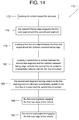
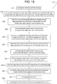
- Figure 14 illustrates an example weather barrier method 170 involving the use of weather barrier apparatus 10.
- block 172 in Figure 14 and arrow 174 in Figure 3 illustrate vehicle 12 moving toward doorway 20.
- Block 176 illustrates rearward facing edge 28 engaging first seal segment 26a and second seal segment 26b of side edge seal 26.
- Block 178 and Figures 2 and 11 illustrate creating or causing a first line of contact 180 between first seal segment 26a and rearward facing edge 28 of vehicle 12.
- Block 182 and Figures 2 and 11 illustrate creating or forming a second line of contact 184 between second seal segment 26b and rearward facing edge 28 of vehicle 12, where second line of contact 184 is substantially collinear with first line of contact 180.
- Block 186 and Figure 2 in comparison to Figure 1 illustrate second seal segment 26b moving relative to first seal segment 26a in a direction substantially parallel to first line of contact 180 and second line of contact 182.
- Block 188 illustrates first seal segment 26a engaging first rear edge 32 of vehicle 12
- block 190 illustrates second seal segment 26b engaging first rear edge 32 of vehicle 12.
- Figure 15 illustrates another example weather barrier method 192 involving the use of weather barrier apparatus 10.
- block 194 and arrow 174 of Figure 3 illustrate vehicle 12 moving toward doorway 20 such that rearward facing edge 28 faces and approaches wall 18 and/or doorway 20.
- Block 196 and Figure 11 illustrate rearward facing edge 28 of vehicle 12 engaging a rear edge seal 198 (e.g., seal 78 and/or 126) of weather barrier apparatus 10.
- Block 200, Figure 13 in comparison to Figure 12 , and arrows 202, 204 and 206 illustrate while backing vehicle 12 toward doorway 20, vehicle 12 shifting weather barrier apparatus 10.
- Block 208, arrow 210 of Figure 13, and Figure 13 in comparison to Figure 12 illustrate in reaction to vehicle 12 shifting weather barrier apparatus 10, upper seal member 24 and/or side seal member 26 increasing in length.
- Arrow 210 of Figure 13 illustrates upper side seal segment 26b sliding along lower side seal segment 26a.
- Figure 16 illustrates another example weather barrier method 212 involving the use of weather barrier apparatus 10.
- block 214 in Figure 16 and arrow 174 of Figure 3 illustrate backing vehicle 12 toward doorway 20.
- Block 216, Figure 5 and Figure 10 illustrate, as a result of backing vehicle 12 toward doorway 20, rearward facing edge 28 engaging rear edge seal 198 (e.g., seal 78 and/or 126) while a surface seal 218 (e.g., seal 80 and/or 128) is spaced apart from vehicle 12.
- rear edge seal 198 e.g., seal 78 and/or 12
- a surface seal 218 e.g., seal 80 and/or 128
- Block 220 and arrow 222 of Figure 10 illustrates after rearward facing edge 28 effectively engages rear edge seal 198 (e.g., seal 78 and/or 126) while a surface seal 224 (e.g., seal 80 and/or 128) is spaced apart from vehicle 12, backing vehicle 12 closer to doorway 20.
- Block 226, comparing Figures 10 and 11 , and comparing Figures 5 and 6 illustrate while backing vehicle 12 closer to doorway 20, pushing rear edge seal 198 closer to doorway 20.
- Block 228, Figures 6 and 11 illustrate in reaction to pushing rear edge seal 198 closer to doorway 20, forcing or causing surface seal 224 into effective engagement with vehicle panel 82 or 130 at a point spaced apart from rear edge seal 198.
- Block 230 and arrow 232 of Figure 10 illustrate while backing vehicle 12 closer to doorway 20, rotating rear edge seal 198 and surface seal 224 about substantially vertical axis 134.
- Block 234 and arrow 236 of Figure 10 illustrate while backing vehicle 12 closer to doorway 20, bending side support member 112 toward vehicle 12.
- Block 238 and arrow 238 of Figure 10 illustrate while backing vehicle 12 closer to doorway 20, moving the substantially vertical axis 122 closer to vehicle panel 130.
- Block 240, a force arrow 242 of Figure 6 and a force arrow 244 of Figure 11 illustrate rear edge seal 198 exerting a first force (force 242 or force 244) against rearward facing edge 28.
- Block 246, a force arrow 248 of Figure 6 and a force arrow 250 of Figure 11 illustrate surface seal 224 exerting a second force (force 248 or 250) against vehicle panel 82 or 130, where first force 242 is greater than second force 248, or first force 244 is greater than second force 250.
- Block 252 illustrates increasing the first force (force 242 or 244).
- Block 254 illustrates increasing the second force (e.g., force 250) in reaction to increasing the first force (e.g., force 244).
Landscapes
- Engineering & Computer Science (AREA)
- Architecture (AREA)
- Mechanical Engineering (AREA)
- Physics & Mathematics (AREA)
- Electromagnetism (AREA)
- Civil Engineering (AREA)
- Structural Engineering (AREA)
- Seal Device For Vehicle (AREA)
- Specific Sealing Or Ventilating Devices For Doors And Windows (AREA)
Description
- The present disclosure relates generally to vehicle-actuated members and, more specifically, to vehicle-actuated weather barrier apparatus.
- Dock weather barriers (weather barrier apparatus), such as dock seals and dock shelters prevent the ingress of outdoor environmental conditions or contaminants (e.g., rain, snow, wind, hot/cold temperatures, insects, animals, etc.) into the interior of a building and/or cargo area of a vehicle during the loading or unloading of the vehicle. Dock shelters and seals also prevent the egress of conditioned air from within a building and/or a vehicle cargo area to the outdoor environment.
- Some known dock seals use side members having a compressible foam core or body surrounded by a coated fabric or vinyl outer layer. The foam core provides sufficient structural rigidity to enable the side members to be extended a short distance from the building wall surrounding the loading dock. The coated fabric outer layer protects the foam core from outdoor environmental conditions (e.g., moisture), provides wear resistance to repeated impacts from the rear portions of vehicles, and may provide desirable aesthetic qualities. Additionally, a header structure may span between the side members along a top portion of the loading dock opening. The header structure may be another compressible member similar in construction to the side members and, in some cases, may include a weighted fabric curtain that hangs downwardly to contact the top of a truck trailer to form an environmental barrier along the top of the trailer.
- Another type of dock seal uses inflatable side members and a header structure having internal compressible resilient pads, which provide some degree of side member compressibility when the side members are in a deflated condition. In either case, when the rear portion of a vehicle (e.g., a truck trailer) is backed into either foam or inflatable dock seal side and header members, the side and header members are compressed toward the building wall to form a seal along the lateral and top back edges of the vehicle. If present, the head curtain sweeps along the top of the trailer to form a seal at the top of the trailer between the side members. Dock seals typically consume a relatively small amount of wall space and can provide a relatively high quality seal between the rear edges of a vehicle and the outside building wall surrounding the dock. However, when the dock seal side members are compressed, they may be displaced into or otherwise encroach on the opening to the rear of the docked vehicle. As a result, the compressed side member may interfere with operation of a fork lift and/or an operator during loading and unloading activities. In addition, inflatable dock seals are susceptible to power losses and tears that compromise the ability of the side members to inflate to provide an acceptable seal.
- In contrast to dock seals, some known dock shelters use side members that are mounted to the outside building wall surrounding the loading dock. The side members are spaced well to the outside of the sides of a docked vehicle. The side members are configured to extend (i.e., to be cantilevered) an appreciable distance from the outside building wall, particularly in cases where a dock leveler protrudes from the dock opening. The side members may also support flexible seal members or side curtains extending inwardly from the side members across at least a portion of the opening defined by the side members. When a vehicle such as, for example, a truck trailer, is backed into the opening of the dock shelter, the inwardly facing edges of the seal members or side curtains resiliently deflect and sweep against the lateral sides of the trailer to form an environmental barrier therebetween. As with dock seals, dock shelters also typically include a header structure, which may include a head curtain, to form an environmental barrier along the top edge of the rear of the vehicle.
- In contrast to dock seals, dock shelters typically provide unobstructed access to a vehicle cargo area opening (i.e., there are no foam pads or the like to be compressed and displaced into the opening adjacent the rear of the vehicle). However, most known dock shelter side members are constructed using rigid wood, fiberglass or metal frames capable of supporting the weight of the seal members or side curtains, which are usually held at an appreciable distance (e.g., several feet) from the building wall. Such side members may be permanently deformed or damaged if they are impacted by a vehicle. Accordingly, bumpers or stops may be mounted to the lower edge of the dock shelter to prevent a vehicle (e.g., a truck trailer) from impacting and damaging the rigid shelter.
- The rigid side members used to implement these known dock shelters are also typically mechanically coupled via the header and/or another rigid member to provide increased lateral rigidity to the dock shelter to minimize the ability of the side members to move from side-to-side. Because of this, the side members typically have to be mounted relatively far apart to accommodate a wide range of possible off-center vehicle positions relative to the opening of the building. This relatively large distance between the rigid side members consumes a significant and, thus, expensive amount of building wall space for each loading dock opening.
- Some example dock shelters employ impactable side members. The impactable side members are similar to those used with dock seals and typically use a foam core or body surrounded by a coated fabric outer layer. Seal members or side curtains, which may be constructed using a fabric and flexible fiberglass stays combination or a foam core and fabric combination, are typically mounted to the side members to extend at least partially across the shelter opening. When a vehicle is backed into the shelter, the inwardly facing edges of the seal members or side curtains deflect and sweep against the sides of the vehicle to form an environmental barrier or seal against the sides of the vehicle. In the event the off-center position of a vehicle results in the rear of the vehicle impacting a side member, the foam core or body of the side member is resiliently compressed. When the vehicle is pulled away from an impacted side member, the foam core of the side member causes the side member to substantially recover or return to its original condition or shape prior to being impacted by the vehicle.
-
CH 600 117 A5 CH 600 117 A5 -
GB 2 115 041 A - The present invention provides a weather barrier apparatus according to the subject-matter of independent claim 1. Preferred embodiments of the invention are set forth in the dependent claims, the following description and the drawings.
-
-
Figure 1 is a perspective view of an example weather barrier apparatus constructed in accordance with the teachings disclosed herein. The example weather barrier apparatus ofFigure 1 is shown in a relaxed configuration and certain curtains and membranes are omitted to show other features of the weather barrier apparatus more clearly. -
Figure 2 is a perspective view similar toFigure 1 but showing the weather barrier apparatus in an activated configuration. -
Figure 3 is a cross-sectional view taken along line 3-3 ofFigure 1 . -
Figure 3a is a cross-sectional view similar toFigure 3 but showing an example seal return member constructed in accordance with the teachings disclosed herein. -
Figure 4 is a cross-sectional view similar toFigure 3 but showing an example vehicle at a position of initial engagement with the example weather barrier apparatus. -
Figure 5 is a cross-sectional view similar toFigures 3 and4 but showing the vehicle further into engagement with the example weather barrier apparatus. -
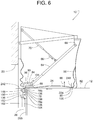
Figure 6 is a cross-sectional view similar toFigures 3 - 5 but showing the vehicle at a parked position and the weather barrier apparatus in an activated configuration. -
Figure 6a is a cross-sectional view similar toFigure 6 but showing the example seal return member illustrated inFigure 3a . -
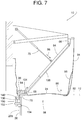
Figure 7 is a cross-sectional view similar toFigures 7 but showing the vehicle at a lower position. -
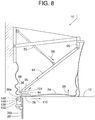
Figure 8 is a cross-sectional view similar toFigure 6 but showing the vehicle departing a loading dock and showing the example weather barrier apparatus in a departing activated configuration. -
Figure 9 is a cross-sectional view taken along line 9-9 ofFigure 1 . -
Figure 10 is a cross-sectional view similar toFigure 9 but showing the vehicle at the position of initial engagement with the example weather barrier apparatus. -
Figure 11 is a cross-sectional view similar toFigures 9 and 10 but showing the vehicle at the parked position with the example weather barrier apparatus in the activated configuration. -
Figure 12 is a front view ofFigure 1 but with the vehicle omitted to show the example weather barrier apparatus more clearly. -
Figure 13 is a front view ofFigure 2 but with the vehicle omitted to show the example weather barrier apparatus more clearly. -
Figure 14 is a block diagram illustrating an example method associated with an example weather barrier apparatus constructed in accordance with teachings disclosed herein. -
Figure 15 is a block diagram illustrating another example method associated with an example weather barrier apparatus constructed in accordance with teachings disclosed herein. -
Figure 16 is a block diagram illustrating another example method associated with an example weather barrier apparatus constructed in accordance with teachings disclosed herein. -
Figures 1 - 13 show an exampleweather barrier apparatus 10 constructed in accordance with the teachings disclosed herein. The exampleweather barrier apparatus 10 ofFigures 1-13 has various vehicle-actuated members to seal or shelter a vehicle 12 (e.g., truck, trailer, etc.) parked at aloading dock 14 of abuilding 16.Building 16 includes awall 18 and adoorway 20 through which cargo is transferred betweenvehicle 12 and aninterior dock area 22 ofbuilding 16. In some examples,vehicle 12 backs into theweather barrier apparatus 10 in a direction towarddoorway 20,vehicle 12 moves and/or lengthens at least one of anupper seal member 24 and a side seal member 26 (e.g., a firstside seal member 26a and a secondside seal member 26b) such thatseal members edge 28 andrear corners 30. Rearward facingedge 28 ofvehicle 12 includes a firstrear edge 32, a secondrear edge 34 and an upperrear edge 36. As a result of theweather barrier apparatus 10 seeking the vehicle's rearward facingedge 28 andcorners 30, theweather barrier apparatus 10 reduces (e.g., minimizes) the seal member's encroachment into and/or obstruction of acargo passageway 38 running betweendoorway 20 and a rear door opening 40 (Fig. 9 ) ofvehicle 12. -
Cargo passageway 38 is defined as a projection ofdoorway 20, wherecargo passageway 38 has apassageway height 42 and apassageway width 44 substantially equal to the doorway'sheight 46 andwidth 48, respectively. The doorway'sheight 46 andwidth 48 lie along a plane 50 (Figs. 3 and9 ) that is generally parallel towall 18. Aline 52 perpendicular to plane 50 extends substantially parallel to the general direction along which cargo travels throughpassageway 38.Wall 18 has anexterior surface 54 facing in aforward direction 56 parallel toline 52. The term, "plane" and "line" means that the plane and the line pertain to geometry as opposed to an actual physical structure. - In some examples, to seek and seal the vehicle's rearward facing
edge 28 andrear corners 30,upper seal member 24 pivots relative to theside seal members 26 and/or the dock wall (e.g., in a downward direction), andside seal members 26 deflect laterally and/or lengthen vertically to accommodate the position and dimensions ofvehicle 12. The movement ofseal members vehicle 12 moving from a departed position in whichvehicle 12 is spaced apart from or disengaged with the weather barrier apparatus 10(e.g., as shown inFigure 1 ) to a parked position in front ofdoorway 20 in which vehicle 12 (e.g., fully) engages weather barrier apparatus 10(e.g., as shown inFigure 2 ). Theweather barrier apparatus 10 is in a relaxed configuration whenvehicle 12 is in the departed position (e.g., as shown inFigures 1 ,3 ,9 and12 ).Vehicle 12 in the parked position causes or forcesweather barrier apparatus 10 to an activated configuration, as shown for example inFigures 2 ,6 - 8 ,11 and13 . - Although the actual structure and function of
weather barrier apparatus 10 may vary, in some examples,upper seal member 24 is part of anoverall header structure 58, andside seal member 26 is part of anoverall side structure 60, wherestructures Figures 3 - 8 ,header structure 58 includes anupper support member 62 attached to the wall'sexterior surface 54, aswing arm 64 with anupper end 66 pivotally coupled toupper support member 62,upper seal member 24 being pivotally coupled to alower end 68 ofswing arm 64, and abrace 70 having oneend 72 connected toupper support member 62 and anopposite end 74 connected to anintermediate point 76 onswing arm 64. To provideupper support member 62 with the ability to restorably yield, flex or resiliently deform in the event of an impact from a vehicle, some examples ofupper support member 62, as shown inFigure 3 , include aframe member 63 pivotal about apin 65.Upper seal member 24 includes anupper edge seal 78 for sealing against the vehicle's upperrear edge 36 and, in some examples, may also include anupper surface seal 80 for sealing against anupper panel 82 ofvehicle 12. In some examples, a shiftable connection 84 (e.g., a slider) couplesupper edge seal 78 to upper seal member'slower end 68. Shiftable connection 84 (which will be explained later in greater detail) eases the disengagement ofupper edge seal 78 and upperrear edge 36 asvehicle 12 departsdock 14 and disengages fromweather barrier apparatus 10. - An example operation of
header structure 58 follows the example sequence illustrated inFigures 3 - 8 .Figure 3 showsvehicle 12 in the departed or disengaged position backing towardheader structure 58. During the approach,vehicle 12 is separated or disengaged fromweather barrier apparatus 10 andheader structure 58 such thatweather barrier apparatus 10 is in the relaxed configuration (e.g., an initial position) withupper seal member 24 being in a lowered or stored position. In the relaxed configuration,swing arm 64 hangs downward to a forward position due to the swing arm's weight, the weight ofupper seal member 24 and/or the force ofbrace 70 pushing or biasingswing arm 64 to the forward position (e.g., biasing thelower end 68 ofswing arm 64 away from the wall 18). In some examples,brace 70 includes aspring 86 that urgesswing arm 64 to the forward position.Spring 86 is schematically illustrated to represent any resilient member being part of or coupled to brace 70. In some examples,spring 86 is provided bybrace 70 itself being a pneumatic spring. - Some examples of
header structure 58 include aspring 88 urgingupper seal member 24 to the generally upright position, as shown inFigure 3 .Spring 88 is schematically illustrated to represent any resilient member (e.g., extension spring, compression spring, pneumatic spring, leaf spring, elastic cord, etc.) that urgesupper seal member 24 to the generally upright position. In the illustrated example,spring 88 urgesupper seal member 24 to rotate (e.g., upwards) about the swing arm'slower end 68 toward thewall 18. In some examples, the swing arm'slower end 68 is an element that slides, shifts, moves or otherwise travels along respective ends of aslot 90 inshiftable connection 84. In some examples, the element is a pin protruding (e.g., laterally) intoslot 90. - In addition or as an alternative to
spring 88, some examples ofheader structure 58 include a seal return member 88' in the form of a pliable elongate member of fixed length extending between onepoint 87 onupper seal member 24 and ananchor point 89 near the lower end ofupper support member 62. Examples of seal return member 88' include, but are not limited to, a strap, a sheet of pliable material, a cable, a chain, a rope, etc. Whenweather barrier apparatus 10 is in the relaxed configuration, as shown inFigure 3a , the linear distance betweenpoints upper seal member 24 to its upright position. Whenweather barrier apparatus 10 is in the activated configuration, as shown inFigure 6a , the distance betweenpoints upper seal member 24 to descend uponvehicle 12. - For greater sealing integrity, some examples of
header structure 58 include at least one of apliable membrane 92a, afront curtain 94 and aback membrane 96.Pliable membrane 92a, in some examples, extends fromupper seal member 24 to aperipheral region 98a ofdoorway 20 to span anoverhead gap 100 that might otherwise exist betweenseal member 24 andwall 18.Front curtain 94, in some examples, hangs from afront edge 102 ofupper support member 62 and helps seal gaps that might exist betweenupper support member 62 and the vehicle'supper panel 82.Back membrane 96, in some examples, extends betweenupper seal member 24 andfront curtain 94 to help seal gaps that might exist in that area. In some examples, each ofmembranes -
Figure 4 shows the initial movement or reaction ofweather barrier apparatus 10 as the vehicle's upperrear edge 36 first engagesheader structure 58. During initial contact, the vehicle's upperrear edge 36 effectively engagesupper seal member 24. The term, "effectively engages" (and derivatives thereof) as used with reference, for example, to a seal member effectively engaging a vehicle means that the seal member either touches the vehicle directly or with some intermediate element (e.g., a curtain membrane) interposed in compression between the seal member and the vehicle. In the illustrated example of, "the vehicle's upperrear edge 36 effectively engagesupper seal member 24," this means that engagement occurs but withfront curtain 94 sometimes being interposed in compression betweenedge 36 andupper seal member 24. During initial engagement,vehicle 12 pushesupper seal member 24 and swing arm 64 (e.g., the lower end 68) back towarddoorway 20 about thepivot 66 of theswing arm 64. The vehicle's pushing force overcomes the spring force ofbrace 70 applied to the swing arm's 64intermediate point 76. As a result,vehicle 12 forcesupper seal member 24 andswing arm 64 to rotate about theupper end 66 ofswing arm 64.Vehicle 12 eventually pushesswing arm 64 to its deflected position shown inFigure 6 asvehicle 12 continues to move toward thedoorway 20. - In the illustrated example,
vehicle 12 continues to move back towarddoorway 20 from the position shown inFigure 4 to an intermediate position shown inFigure 5 . In doing so, the vehicle's upperrear edge 36 slides alongupper seal member 24 until the vehicle's upperrear edge 36 engagesupper edge seal 78, thereby placingweather barrier apparatus 10 in an intermediate configuration, as shown inFigure 5 . From the position shown inFigure 5 ,vehicle 12 continues moving back towardwall 18 to the position shown inFigure 6 . InFigure 6 ,vehicle 12 is shown in the parked position (e.g., a loading/unloading position) withweather barrier apparatus 10 in an activated configuration andupper seal member 24 in a raised or sealing position. Asvehicle 12 moves back toward thedoorway 20 from the position shown inFigure 5 to that shown inFigure 6 , several things happen. - One, the rearward force that
vehicle 12 exerts againstupper seal member 24 coupled with the force that spring 86 exerts againstswing arm 64 causesupper seal member 24 and shiftable link 84 to rotate (e.g., squarely) against the vehicle's upperrear edge 36. Upperrear edge 36 is a general region ofvehicle 12, where upperrear edge 36, more specifically, includes arear portion 36a and atop portion 36b (Fig. 3 ).Rear portion 36a generally faces towarddoorway 20, andtop portion 36b faces generally upward. The rotation ofupper seal member 24 rotatesupper seal member 24 downward toward the vehicle'supper panel 82. This placesupper surface seal 80 ofupper seal member 24 in effective engagement withupper panel 82. In some examples,upper surface seal 80 engagesupper panel 82 directly, and in other examples, a lower end offront curtain 94 is (e.g., compressively) interposed betweenupper surface seal 80 andupper panel 82. - Two,
vehicle 12 pushingupper seal member 24 andshiftable connection 84 back whilebrace 70 attempts holding the swing arm'slower end 68 stationary causes relative sliding motion between the swing link'slower end 68 andshiftable connection 84. The relative sliding motion moves the swing link'slower end 68 to the front end of the shiftable connection's slot 90 (e.g., pin orlower end 68 moves or slides from one end ofslot 90 to the other end of slot 90). - Three, after the swing link's
lower end 68 reaches the forward end of travel withinslot 90,vehicle 12 continues pushingupper edge seal 78 andshiftable connection 84 back towarddoorway 20. In some examples,swing arm 64 is extendable (e.g., telescopic). As a result,vehicle 12 continued push ofupper edge seal 78 andshiftable connection 84 back towarddoorway 20 forces swingarm 64 to extend in opposition to a spring or biasingelement 104 associated withswing arm 64 andshiftable connection 84.Spring 104 is schematically illustrated to represent any means for urgingswing arm 64 to the retracted position (e.g., a position providing a minimum length) and/or for urgingshiftable connection 84 toward the swing arm'supper end 66. Examples ofspring 64 include, but are not limited to, an extension spring, a compression spring, a pneumatic spring, a leaf spring, an elastic cord, etc. In some examples,spring 104 is an extension spring positioned within or inside a housing ofswing arm 64 with opposite ends ofspring 104 being connected to the swing arm'supper end 66 andshiftable connection 84. In some examples,spring 104 is an extension spring on the exterior ofswing arm 64 with opposite ends ofspring 104 being connected to the swing arm'supper end 66 andshiftable connection 84. - With
vehicle 12 in the parked position andweather barrier apparatus 10 in the activated configuration, as shown inFigures 6 and6a ,upper edge seal 78 effectively engages and seals against the vehicle's upperrear edge 36. In addition or alternatively, in some examples,upper surface seal 80 effectively engages and seals against the vehicle'supper panel 82. In some examples,upper edge seal 78 includes acatch 78a and/or afoot 78b. In some examples, catch 78a effectively engages and seals againstrear portion 36a of the vehicle's upperrear edge 36. In some examples, catch 78a effectively engages but does not necessarily seal againstrear portion 36a. In some examples,foot 78b effectively engages and seals againsttop portion 36b of the vehicle's upperrear edge 36. In some examples,foot 78b effectively engages but does necessarily seal againsttop portion 36b of the vehicle's upperrear edge 36. - To enhance sealing, some examples of
foot 78b,catch 78a andupper surface seal 80 include a sealingelement 106 that compliantly seals against the vehicle's upperrear edge 36 and/orupper panel 82.Sealing element 106 is schematically illustrated to represent any compliant feature that promotes or effects sealing. Examples of sealingelement 106 include, but are not limited to, a rubber pad, a foam pad, a gasket, one or more lips of flexible strips of material, flexible pleats, and a sheet of flexible material formed to create a compressible bulb or loop, etc. -
Figure 7 shows the configuration ofheader structure 58 when the vehicle'supper panel 82 is lower than the position of theupper panel 82 shown inFigure 6 . For example, theupper panel 82 may move to a lower position relative todoorway 20 when heavy cargo and/or a forklift enter the cargo bay ofvehicle 12. In other cases, instead ofvehicle 12 being positioned at the height shown inFigure 6 , a vehicle having a smaller overall height might enterdock 14. When the vehicle'supper panel 82 descends or is otherwise at a lower position as shown inFigure 7 , brace 70 under spring force extends towardswing arm 64 to hold upper edge seal 78 (e.g., downward) in engagement against the vehicle's upperrear edge 36.Swing arm 64 having avariable length 108 providesupper edge seal 78 with a freedom of travel (e.g., vertical travel) that allowsupper edge seal 78 to follow the vertical movement of the vehicle's upperrear edge 36. - After loading or unloading
vehicle 12 andvehicle 12 begins departingdock 14, as shown inFigure 8 , the vehicle's initialforward movement 110 away fromdoorway 20 causesrear edge seal 78 andshiftable connection 84 to move forward as well. Lost motion of the brace'slower end 68 relative toshiftable connection 84 shiftslower end 68 to the back end of slot 90 (i.e., causeslower end 68 to move between the forward and rearward ends of the slot 90), as shown inFigure 8 . AlthoughFigures 6 and8 showweather barrier apparatus 10 in the activated configuration,Figure 6 showsweather barrier apparatus 10 in an arriving activated configuration, andFigure 8 showsweather barrier apparatus 10 in a departing activated configuration.Spring 104 acting uponshiftable connection 84 urgesweather barrier apparatus 10 to the departing activated configuration. The shifting motion atshiftable connection 84 positions the brace'slower end 68 near or behind therear portion 36a of the vehicle's upperrear edge 36, soupper seal member 24 readily "falls off' or disengages upperrear edge 36 asvehicle 12 departs and moves away fromdoorway 20. In some examples, to prevent a similar releasing action asvehicle 12 vacillates vertically and/or back-and-forth during loading and unloading operations, slot 90 is at a slight incline to bias the brace'sbottom end 68 toward the forward end ofslot 90. -
Header structure 58 can be used alone or with various types of side sealing structures. Referring toFigures 1 and2 and further toFigures 9 - 11 , some examples ofside structure 60 include aside support member 112 attached to wall 18,side seal member 26 pivotally attached toside support member 112, and, in some examples, apliable membrane 92b extending fromside seal member 26 to aperipheral region 98b ofdoorway 20.Pliable membrane 92b spans alateral gap 114 that might otherwise exist betweenside seal member 26 andperipheral region 98b. - In the illustrated example,
side support member 112 comprises twoflexible panels 116 spaced apart at a mounting base 118 and converge or come together at an apex 120 whereside seal member 26 connects to sidesupport member 112.Apex 120 is at a vertically extendingpivotal axis 122 about whichside seal member 26 pivots relative toside support member 112. In some examples, a flexible fabric lap joint atapex 120 pivotally connectsside seal member 26 toside support member 112. In some examples, resiliently compressible foam fills the space betweenpanels 116. In some examples,side support member 112 is hollow betweenpanels 116. In some examples,side support member 112 includes awindow 124. -
Side seal member 26, in some examples, includes aside edge seal 126 and/or aside surface seal 128, wherepivotal axis 122 lies betweenseals vehicle 12 is in the parked position andweather barrier apparatus 10 is in the activated configuration,side support member 112 responds by bending towardvehicle 12 such thatside edge seal 126 effectively engagesrear edge 32 andside surface seal 128 engages aside panel 130 ofvehicle 12, as shown inFigure 11 . The bending motion ofside support member 112 positionspivotal axis 122 closer tovehicle 12 whenvehicle 12 is at the parked position (Fig. 11 ) than whenvehicle 12 is at the departed position (Fig. 9 ) or at the intermediate position (Fig. 10 ).Side panel 130 is any vehicular surface that is approximately vertical and facing in a direction that is approximately perpendicular toline 52. Examples ofside panel 130 include, but are not limited to, the side of vehicle 12 (e.g., where the vehicle has a rear door that operates vertically) and a side (e.g., an inner surface) of a swung-openrear door panel 132 of vehicle 12 (e.g.,door panel 132 being hinged to the vehicle's rearward facing edge 28). - An example operation of
side structure 60 follows the example sequence illustrated inFigures 9 - 11 .Figure 9 showsvehicle 12 in the departed position backing or moving towardside structure 60. During this approach,vehicle 12 is separated fromweather barrier apparatus 10 andside structure 60, and soweather barrier apparatus 10, as shown inFigure 9 , is in the relaxed configuration andside seal member 26 is in the preparatory or stored position. In the relaxed configuration,side seal member 26 is biased to positionside edge seal 126 withincargo passageway 38. -
Figure 10 shows the vehicle's initial contact withside seal member 26 asvehicle 12 moves towarddoorway 20. In this example, the vehicle'srear edge 32 engagesside seal member 26 along a generally vertical line or area ofcontact 134 betweenside edge seal 126 andpivotal axis 122. From the position shown inFigure 10 , asvehicle 12 continues moving back towarddoorway 20,side seal member 26 andside support member 112 deflect, as shown inFigure 11 . -
Figure 11 showsvehicle 12 at the parked position withweather barrier apparatus 10 in the activated configuration (e.g.,vehicle 12 is positioned for loading/unloading operation). In the activated configuration,side edge seal 126 effectively engages the vehicle'srear edge 32, and in some examples,side surface seal 128 effectively engages the vehicle'sside panel 130.Side structure 60 can be used alone and/or with various types of header structures. In some examples,side structure 60 can be configured (e.g., positioned horizontally) and used as a header structure, whereside structure 60 is generally horizontally elongate and installed abovedoorway 20. In some examples,header structure 58 can be configured (e.g., turned upright) and used as a side structure, whereheader structure 58 is generally vertically elongate and installed on either side ofdoorway 20. - In some examples where
weather barrier apparatus 10 includes bothheader structure 58 andside structure 60, as shown inFigures 1-8 , acoupling 136 betweenseal members upper seal member 24 with vertical lengthening or sliding (e.g., vertical positioning) ofside structure 60. Coupling 136 in combination withside structure 60 being vertically extendable enables theseal members weather barrier apparatus 10 to seek and seal against the vehicle's rearward facingedges 28 andcorners 30 with minimal obstruction ofcargo passageway 38. - To render
side structure 60 vertically extendable, theside seal member 26 includes a lowerside seal segment 26a connected to an upperside seal segment 26b such that one segment can slide vertically relative to the other segment. In some examples, as shown inFigures 1 ,12 and 13 , lowerside seal segment 26a is pivotally attached toside support member 112, and both are of a fixed vertical length (e.g.,side support member 112 has a substantially constantvertical length 138 as shown inFig. 12 ). Upperside seal segment 26b is nested within lowerside seal segment 26a. Upperside seal segment 26b can slide vertically along lowerside seal segment 26a while upperside seal segment 26b is constrained laterally betweenedges side seal segment 26a. In some examples, an upper side seal segment similar in function to upperside seal segment 26b is attached to the back face of lowerside seal segment 26a. Such back-mounted upper side seal segments include guide rods, a vertical slit and/or other features for accommodating the pivotal connection (at axis 122) betweenside support member 112 and the backside of lowerside seal segment 26a. - Coupling 136 helps hold
side edge seal 126 adjacent toupper edge seal 78 at acorner region 144 ofweather barrier apparatus 10. Coupling 136 maintains edge seals 78 and 126 in closest proximity atcorner region 144 regardless of whetherbarrier apparatus 10 is in the relaxed or activated configuration.Corner region 144 is the area ofweather barrier apparatus 10 that moves into position to seal the general area of the vehicle's upperrear corners 30. Specifically, in some examples,corner region 144 is at a first location (Fig. 12 ) whenweather barrier apparatus 10 is in the relaxed configuration, andcorner region 144 is at a second location (Fig. 13 ) whenweather barrier apparatus 10 is in the activated configuration. In other words, theexample corner region 144 moves in a first direction (e.g., a vertical direction) and a second direction (e.g., a horizontal direction) different than the first direction whenvehicle 12 engages and disengages theweather barrier apparatus 10. For example, in the illustrated example, the first location is within or adjacent cargo passageway 38and the second location is higher than the first location such that the second location is further away from thecargo passageway 38.Upper edge seal 78 at the second location is interposed betweendoorway 20 andvehicle 12 whenvehicle 12 is at the parked position, andside edge seal 126 at the second location is interposed betweendoorway 20 andvehicle 12 whenvehicle 12 is at the parked position. - To achieve such function, in some examples,
coupling 136 is generally L-shaped with afirst leg 146 that is horizontally elongate and slides lengthwise within atube 148 that is attached directly or indirectly toupper seal member 24.Tube 148 provides an axially slidable connection betweenfirst leg 146 andupper seal member 24. The axially slidable connection enablesweather barrier apparatus 10 to accommodate vehicles of various widths. In some examples, the axially slidable connection also provides a rotatable connection betweenfirst leg 146 andupper seal member 24.First leg 146 being able to rotate withintube 148 enablesweather barrier apparatus 10 to move through the various positions shown inFigures 3 - 6 . In this example,coupling 136 has asecond leg 150 that is vertically elongate and points downward. Apivotal link 152 connectssecond leg 150 to alug 154 protruding from upper side seal segment 126b. Apin 156 pivotally connectspivotal link 152 to lug 154, and ahead 158 on the lower end ofsecond leg 150 holdspivotal link 152 engaged tosecond leg 150. With this arrangement, upperside seal segment 26b hangs suspended fromupper seal member 24, wherebyheader structure 58 carries at least some weight of upperside seal segment 26b. - As
vehicle 12 backs intoweather barrier apparatus 10 and pushesupper seal member 24 upward,coupling 136 pulls upperside seal segment 26b up with it such thatrear edge seal 78 and upperside seal segment 26b rise together. Thus,side seal member 26 lengthens while the length ofside support member 112 stays constant. Due toside seal member 26 having an adjustablevertical length 160,side structure 60 has a variable overall length 161 that is significantly greater in the activated configuration (Fig. 13 ) than in the relaxed configuration (Fig. 12 ). The expression, "a variable overall length that is significantly greater in the activated configuration than in the relaxed configuration," means, in some examples, that the variable overall length is at least 15 cm (6 inches) greater in the activated configuration than in the relaxed configuration and that the change in length is not merely the result of inconsequential expansion or distortion due to inflation or foam compression. - As
vehicle 12 backs intoweather barrier apparatus 10,coupling 136 also allowsside edge seal 126 to move laterally outward (to seek the vehicle's verticalrear edges 32 and 34) while maintainingside edge seal 126 andupper edge seal 78 in proximity with each other atcorner region 144. The coupling'sleg 146 sliding withintube 148 allows coupling 136 to follow the lateral movement ofside edge seal 126. - In examples where
pivotal coupling 136 includespivotal link 152, as opposed toleg 150 being pivotally connected to lug 154 directly,pivotal link 152 provides offsetpivotal axes second leg 150 definesfirst axis 162 andpin 166 definessecond axis 164.Pivotal link 152 renderssecond leg 150 rotatable aboutsecond axis 164. The offset betweenaxes rear edge 36 that is horizontally offset to the vehicle's verticalrear edges Figure 3 , for example, showsvehicle 12 with an offsetdistance 168 between upperrear edge 36 andedges -
Figure 14 illustrates an exampleweather barrier method 170 involving the use ofweather barrier apparatus 10. In this example, block 172 inFigure 14 andarrow 174 inFigure 3 illustratevehicle 12 moving towarddoorway 20.Block 176 illustrates rearward facingedge 28 engagingfirst seal segment 26a andsecond seal segment 26b ofside edge seal 26.Block 178 andFigures 2 and11 illustrate creating or causing a first line ofcontact 180 betweenfirst seal segment 26a and rearward facingedge 28 ofvehicle 12.Block 182 andFigures 2 and11 illustrate creating or forming a second line ofcontact 184 betweensecond seal segment 26b and rearward facingedge 28 ofvehicle 12, where second line ofcontact 184 is substantially collinear with first line ofcontact 180.Block 186 andFigure 2 in comparison toFigure 1 illustratesecond seal segment 26b moving relative tofirst seal segment 26a in a direction substantially parallel to first line ofcontact 180 and second line ofcontact 182.Block 188 illustratesfirst seal segment 26a engaging firstrear edge 32 ofvehicle 12, and block 190 illustratessecond seal segment 26b engaging firstrear edge 32 ofvehicle 12. -
Figure 15 illustrates another exampleweather barrier method 192 involving the use ofweather barrier apparatus 10. In this example, block 194 andarrow 174 ofFigure 3 illustratevehicle 12 moving towarddoorway 20 such that rearward facingedge 28 faces and approacheswall 18 and/ordoorway 20.Block 196 andFigure 11 illustrate rearward facingedge 28 ofvehicle 12 engaging a rear edge seal 198 (e.g., seal 78 and/or 126) ofweather barrier apparatus 10.Block 200,Figure 13 in comparison toFigure 12 , andarrows vehicle 12 towarddoorway 20,vehicle 12 shiftingweather barrier apparatus 10.Block 208,arrow 210 ofFigure 13, and Figure 13 in comparison toFigure 12 illustrate in reaction tovehicle 12 shiftingweather barrier apparatus 10,upper seal member 24 and/orside seal member 26 increasing in length.Arrow 210 ofFigure 13 illustrates upperside seal segment 26b sliding along lowerside seal segment 26a. -
Figure 16 illustrates another exampleweather barrier method 212 involving the use ofweather barrier apparatus 10. In this example, block 214 inFigure 16 andarrow 174 ofFigure 3 illustrate backingvehicle 12 towarddoorway 20.Block 216,Figure 5 andFigure 10 illustrate, as a result ofbacking vehicle 12 towarddoorway 20, rearward facingedge 28 engaging rear edge seal 198 (e.g., seal 78 and/or 126) while a surface seal 218 (e.g., seal 80 and/or 128) is spaced apart fromvehicle 12.Block 220 andarrow 222 ofFigure 10 illustrates after rearward facingedge 28 effectively engages rear edge seal 198 (e.g., seal 78 and/or 126) while a surface seal 224 (e.g., seal 80 and/or 128) is spaced apart fromvehicle 12, backingvehicle 12 closer todoorway 20.Block 226, comparingFigures 10 and11 , and comparingFigures 5 and6 illustrate while backingvehicle 12 closer todoorway 20, pushingrear edge seal 198 closer todoorway 20.Block 228,Figures 6 and11 illustrate in reaction to pushingrear edge seal 198 closer todoorway 20, forcing or causingsurface seal 224 into effective engagement withvehicle panel rear edge seal 198.Block 230 andarrow 232 ofFigure 10 illustrate while backingvehicle 12 closer todoorway 20, rotatingrear edge seal 198 andsurface seal 224 about substantiallyvertical axis 134.Block 234 and arrow 236 ofFigure 10 illustrate while backingvehicle 12 closer todoorway 20, bendingside support member 112 towardvehicle 12.Block 238 andarrow 238 ofFigure 10 illustrate while backingvehicle 12 closer todoorway 20, moving the substantiallyvertical axis 122 closer tovehicle panel 130.Block 240, aforce arrow 242 ofFigure 6 and aforce arrow 244 ofFigure 11 illustraterear edge seal 198 exerting a first force (force 242 or force 244) against rearward facingedge 28.Block 246, aforce arrow 248 ofFigure 6 and aforce arrow 250 ofFigure 11 illustratesurface seal 224 exerting a second force (force 248 or 250) againstvehicle panel first force 242 is greater thansecond force 248, orfirst force 244 is greater thansecond force 250.Block 252 illustrates increasing the first force (force 242 or 244).Block 254 illustrates increasing the second force (e.g., force 250) in reaction to increasing the first force (e.g., force 244).
Claims (11)
- A weather barrier apparatus for at least one of sealing or sheltering a vehicle (12) parked at a loading dock (14) of a building (16) that has a doorway (20) in a wall, the wall defining a cargo passageway (38) passing through the doorway (20) having a passageway height and a passageway width corresponding to a doorway height and a doorway width, respectively, the vehicle (12) to have selectively a parked position and a departed position, the vehicle (12) in the parked position being in front of the doorway (20) and engaging the weather barrier apparatus, the vehicle (12) in the departed position being separated from the weather barrier apparatus, the weather barrier apparatus being in an activated configuration when the vehicle (12) is in the parked position and a relaxed configuration when the vehicle (12) is in the departed position,
the weather barrier apparatus comprising a side structure (60) to be positioned alongside the doorway (20), the side structure (60) being generally vertically elongate and having a variable overall length (161) that is significantly greater in the activated configuration than in the relaxed configuration, the side structure (60) extending laterally farther into the cargo passageway (38) toward a center of the doorway (20) in the relaxed configuration than in the activated configuration,
wherein the side structure (60) comprises a side support member (112) to be attached to the wall (18) and a side seal member (26) attached to the side support member (112), the side seal member (26) to effectively engage the vehicle (12) when the weather barrier apparatus (10) is in the activated configuration, both the side support member (112) and the side seal member (26) being vertically elongate, the side support member (112) having a substantially constant vertical length, the side seal member (26) having an adjustable vertical length (160) that provides the side structure with the variable overall length (161)
wherein the side seal member (26) includes a lower side seal segment (26a) and an upper side seal segment (26b), and both the lower side seal segment (26a) and the upper side seal segment (26b) engage the vehicle (12) when the weather barrier apparatus is in the activated configuration,
characterized in that the lower side seal segment (26a) is slidingly coupled to the upper side seal segment (26b) to provide the side structure (60) with the variable overall length. - The weather barrier apparatus of claim 1, further comprising a header structure (58) being horizontally elongate, the header structure (58) to be attached to the wall and extending above the doorway (20), the header structure (58) comprising an upper edge seal (78) to engage the vehicle (12) when the weather barrier apparatus is in the activated configuration, the upper edge seal (78) being higher when the weather barrier apparatus is in the activated configuration than when the weather barrier apparatus is in the relaxed configuration whereby the upper edge seal (78) is to rise in response to the vehicle (12) moving from the departed position to the parked position, the upper side seal segment (26b) being proximate the upper edge seal (78) when the weather barrier apparatus is in the relaxed configuration, and the upper side seal segment (26b) being proximate the upper edge seal (78) when the weather barrier apparatus is in the activated configuration whereby the upper side seal segment (26b) is to rise with the upper edge seal (78) in response to the vehicle (12) moving from the departed position to the parked position.
- The weather barrier apparatus of claim 2, wherein the header structure (58) supports at least some weight of the upper side seal segment (26b).
- The weather barrier apparatus of claim 3, wherein the header structure (58) comprises an upper support member (62) to be attached to the wall and an upper seal member (24) suspended from the upper support member (62), the upper edge seal (78) being borne by the upper seal member (24), and the upper side seal segment (26b) being suspended from the upper seal member (24).
- The weather barrier apparatus of claim 4, further comprising a coupling connecting the upper seal member (24) to the upper side seal segment (26b).
- The weather barrier apparatus of claim 5, wherein the coupling includes a first leg connected to the upper seal member (24), the first leg being horizontally elongate, the coupling also includes a second leg connected to the upper side seal segment (26b), the second leg being vertically elongate relative the first leg.
- The weather barrier apparatus of claim 6, wherein the first leg is connected to the upper seal member (24) by way of an axially slidable connection between the first leg and the upper seal member (24).
- The weather barrier apparatus of claim 7, wherein the axially slidable connection further provides a rotatable connection between the first leg and the upper seal member (24).
- The weather barrier apparatus of claim 6, wherein the second leg is connected to the upper side seal segment (26b) by way of a pivotal link, the pivotal link defining a first pivotal axis substantially collinear with the second leg, and the pivot link defining a second pivotal axis offset and substantially parallel to the second leg, the second pivotal axis being adjacent to the upper side seal segment (26b), and the second leg being rotatable about the second pivotal axis.
- The weather barrier apparatus of claim 1, further comprising a header structure (58) being horizontally elongate, the header structure (58) to be attached to the wall and extending above the doorway (20), the header structure (58) comprising an upper edge seal (78) to engage the vehicle (12) when the weather barrier apparatus is in the activated configuration, the side structure (60) including a side edge seal (126) to engage the vehicle (12) when the weather barrier apparatus is in the activated configuration, the side edge seal (126) and the upper edge seal (78) defining a corner region (144) in which the side edge seal (126) and the upper edge seal (78) are in closest proximity with each other, the corner region (144) being at a first location when the weather barrier apparatus is in the relaxed configuration and the corner region (144) being at a second location when the weather barrier apparatus is in the activated configuration, the first location being within the cargo passageway (38), the second location being higher than the first location, the upper edge seal (78) at the second location being interposed between the doorway (20) and the vehicle (12) when the vehicle (12) is at the parked position, and the side edge seal (126) at the second location being interposed between the doorway (20) and the vehicle (12) when the vehicle (12) is at the parked position.
- The weather barrier apparatus of claim 1, wherein the side structure (60) includes a side edge seal (126) that is interposed between the vehicle (12) and the doorway (20) when the weather barrier apparatus is in the activated configuration.
Priority Applications (1)
| Application Number | Priority Date | Filing Date | Title |
|---|---|---|---|
| EP21179984.6A EP3909895A1 (en) | 2013-07-02 | 2014-06-25 | Vehicle-actuated weather barrier apparatus |
Applications Claiming Priority (2)
| Application Number | Priority Date | Filing Date | Title |
|---|---|---|---|
| US13/933,805 US9162832B2 (en) | 2013-07-02 | 2013-07-02 | Vehicle-actuated weather barrier apparatus |
| PCT/US2014/044107 WO2015002785A1 (en) | 2013-07-02 | 2014-06-25 | Vehicle-actuated weather barrier apparatus |
Related Child Applications (2)
| Application Number | Title | Priority Date | Filing Date |
|---|---|---|---|
| EP21179984.6A Division EP3909895A1 (en) | 2013-07-02 | 2014-06-25 | Vehicle-actuated weather barrier apparatus |
| EP21179984.6A Division-Into EP3909895A1 (en) | 2013-07-02 | 2014-06-25 | Vehicle-actuated weather barrier apparatus |
Publications (2)
| Publication Number | Publication Date |
|---|---|
| EP3016895A1 EP3016895A1 (en) | 2016-05-11 |
| EP3016895B1 true EP3016895B1 (en) | 2021-07-21 |
Family
ID=51205621
Family Applications (2)
| Application Number | Title | Priority Date | Filing Date |
|---|---|---|---|
| EP21179984.6A Pending EP3909895A1 (en) | 2013-07-02 | 2014-06-25 | Vehicle-actuated weather barrier apparatus |
| EP14739656.8A Active EP3016895B1 (en) | 2013-07-02 | 2014-06-25 | Vehicle-actuated weather barrier apparatus |
Family Applications Before (1)
| Application Number | Title | Priority Date | Filing Date |
|---|---|---|---|
| EP21179984.6A Pending EP3909895A1 (en) | 2013-07-02 | 2014-06-25 | Vehicle-actuated weather barrier apparatus |
Country Status (6)
| Country | Link |
|---|---|
| US (5) | US9162832B2 (en) |
| EP (2) | EP3909895A1 (en) |
| CN (1) | CN105517926B (en) |
| CA (1) | CA2916510C (en) |
| ES (1) | ES2885677T3 (en) |
| WO (1) | WO2015002785A1 (en) |
Families Citing this family (10)
| Publication number | Priority date | Publication date | Assignee | Title |
|---|---|---|---|---|
| US9162832B2 (en) | 2013-07-02 | 2015-10-20 | Rite-Hite Holding Corporation | Vehicle-actuated weather barrier apparatus |
| US9642315B2 (en) | 2015-03-11 | 2017-05-09 | Emerald Kingdom Greenhouse, Llc | Top furling automated retractable greenhouse cover |
| US10131509B2 (en) * | 2015-03-23 | 2018-11-20 | Nordock, Inc. | Pit seal and 360-degree trailer seal for a telescoping lip dock leveler |
| US9592972B1 (en) | 2015-08-24 | 2017-03-14 | Rite-Hite Holding Corporation | Sealing members for weather barriers |
| US9624049B1 (en) | 2016-03-17 | 2017-04-18 | Rite-Hite Holding Corporation | Puncture resistant seals for loading docks |
| US9914603B2 (en) * | 2016-03-31 | 2018-03-13 | Rite-Hite Holding Corporation | Weather barriers for vehicle loading docks |
| US9944474B2 (en) * | 2016-08-16 | 2018-04-17 | Rite-Hite Holding Corporation | Adjustable lateral seals for dock weather barriers |
| US11230448B2 (en) * | 2018-01-05 | 2022-01-25 | DL Manufacturing, Inc. | Actuated head pad for loading dock |
| US11254527B2 (en) | 2019-04-05 | 2022-02-22 | Safe Rack Llc | Gangway having self-raising assembly |
| US11273999B1 (en) * | 2020-09-04 | 2022-03-15 | Leum Engineering, Inc. | Modular loading dock with integrated leveler |
Family Cites Families (110)
| Publication number | Priority date | Publication date | Assignee | Title |
|---|---|---|---|---|
| US1327807A (en) | 1918-10-26 | 1920-01-13 | Paul B Burleigh | Toothbrush |
| FR545837A (en) | 1922-01-09 | 1922-10-21 | C & E Streisguth | Artificial hand |
| US2087758A (en) | 1936-07-02 | 1937-07-20 | Circo Products Company | Gripping device |
| US2273207A (en) | 1939-08-09 | 1942-02-17 | John W Kuhn | Toothbrush |
| US2688164A (en) | 1952-07-21 | 1954-09-07 | Paul R Grosjean | Bumper door |
| FR1068390A (en) | 1952-12-18 | 1954-06-24 | Jaw pliers with jaws | |
| FR1087906A (en) | 1953-08-08 | 1955-03-01 | Kleber Colombes | Improvements made to elastic bands or plates, in particular for devices for closing openings or orifices |
| US2706825A (en) | 1954-04-02 | 1955-04-26 | Amoron R Blakeman | Toothbrush |
| US2892463A (en) | 1954-05-27 | 1959-06-30 | Dubuque Awning & Tent Co | Loading dock shield |
| US3091808A (en) | 1960-02-19 | 1963-06-04 | Gen Motors Corp | Vacuum forming drum |
| US3322132A (en) | 1964-05-13 | 1967-05-30 | J M Nash Company Inc | Loading dock shelter |
| US3216433A (en) | 1964-06-11 | 1965-11-09 | Azzo Errol P D | Loading dock shelter |
| US3406422A (en) | 1966-08-22 | 1968-10-22 | Joseph J. Nichols | Mop wringer |
| US3352314A (en) | 1967-02-24 | 1967-11-14 | Dubque Awning & Tent Co | Loading dock shelter |
| US3375625A (en) | 1967-05-24 | 1968-04-02 | Medalist Ind Inc | Door seal |
| US3461627A (en) | 1967-09-18 | 1969-08-19 | Gary L Conger | Sealing device for loading docks and the like |
| US3538655A (en) | 1968-04-11 | 1970-11-10 | Dubuque Awning & Tent Co | Loading dock shelters |
| BE754804A (en) | 1969-08-14 | 1971-01-18 | Budd Co | BELLOWS DEVICE FOR MOBILE AIRCRAFT LOADING GATEWAY |
| US3731828A (en) * | 1970-01-07 | 1973-05-08 | E Clarke | Bulk material handling system |
| US3665997A (en) | 1970-02-20 | 1972-05-30 | Overhead Door Corp | Adjustable dock seal assembly |
| US3638667A (en) | 1970-05-05 | 1972-02-01 | Dubuque Awning & Tent Co | Loading dock shelters |
| US3641604A (en) * | 1970-05-27 | 1972-02-15 | Boothe Airside Services | Closure apparatus |
| US3811222A (en) | 1971-01-26 | 1974-05-21 | G Economou | Swinging doors |
| US3750739A (en) | 1972-02-07 | 1973-08-07 | Mc Guire Co Inc | Flexible traffic door |
| DE2238675A1 (en) | 1972-08-05 | 1974-02-14 | Porsche Ag | REST FURNITURE |
| FR2266805A1 (en) | 1974-04-03 | 1975-10-31 | Rolls Royce | Jet engine with noise control platform - having elongate slot nozzles emitting curtain of working medium deflecting part of jet energy |
| US3951395A (en) | 1974-11-25 | 1976-04-20 | Control Data Corporation | Resilient vise jaw |
| US4003170A (en) | 1975-10-15 | 1977-01-18 | W. B. Mcguire Co., Inc. | Loading dock shelter structure |
| CH600117A5 (en) | 1976-02-24 | 1978-06-15 | Kempf & Co Ag | Haulage vehicle loading dock seal |
| US4070801A (en) * | 1976-10-04 | 1978-01-31 | Neal Larry O | Flexible dock seal |
| US4120067A (en) | 1978-03-15 | 1978-10-17 | Abex Corporation | Articulated closure for a passenger loading bridge |
| AU6563380A (en) | 1979-12-19 | 1983-01-06 | Mckinlay, I.B. | Foils operating in fluid medium |
| US4333195A (en) | 1980-11-24 | 1982-06-08 | Lichti Robert D | Fire protective walkway apparatus |
| GB2115041B (en) | 1982-01-25 | 1985-07-31 | Power Loading Limited | Dock shelter |
| US4494341A (en) | 1982-08-26 | 1985-01-22 | Kelley Company Inc. | Dock shelter with improved adjustable head pad |
| DE3233915C2 (en) | 1982-09-13 | 1987-02-12 | Oerlikon-Boehringer GmbH, 7320 Göppingen | Clamping jaw for clamping devices, especially for multi-jaw chucks of machine tools |
| US4554768A (en) | 1983-04-21 | 1985-11-26 | Woodford Manufacturing Company | Dock seal with adjustable top seal |
| US4574543A (en) * | 1983-08-11 | 1986-03-11 | Crosson Robert J | Truck bay door apparatus |
| US5240308A (en) | 1983-11-09 | 1993-08-31 | Goldstein Glenn A | Ergonomic adjustable chair and method |
| US4671029A (en) * | 1985-10-28 | 1987-06-09 | Kelley Company, Inc. | Dock shelter |
| DE8600773U1 (en) * | 1986-01-15 | 1986-03-27 | Gebr. Koch & Co, 4937 Lage | Deformable seal of the gap between a building opening and a vehicle approaching it |
| US4719826A (en) | 1986-06-02 | 1988-01-19 | Dubois Roger D | Light bulb extractor |
| DE3629787A1 (en) | 1986-09-02 | 1988-03-03 | Alten K | DEFORMABLE SEAL OF THE GAP BETWEEN THE EDGE OF A BUILDING OPENING AND THE REAR OF A VEHICLE APPROACHED TO THIS |
| US4805362A (en) * | 1987-09-23 | 1989-02-21 | Frommelt Industries, Inc. | Hook seal for loading dock shelter |
| DE4002972C2 (en) | 1990-02-01 | 1994-06-16 | Guenter Waldherr | Wing with changeable profile, especially for use as a sail |
| DE4111367A1 (en) | 1990-09-25 | 1992-03-26 | Alten K | DEFORMABLE GASKET OF THE GAP BETWEEN THE EDGE OF A BUILDING OPENING AND THE REAR OF A VEHICLE APPROACHED TO THIS |
| DE4038372A1 (en) | 1990-12-01 | 1992-06-04 | Schlerf Coronet Werke | WRING-OUT DEVICE FOR CLEANING ELEMENTS OF WET-CLEANING DEVICES |
| US5125196A (en) | 1991-04-30 | 1992-06-30 | Kelley Company Inc. | Dock seal header construction |
| DE4121768C1 (en) | 1991-07-02 | 1992-10-08 | Grammer Ag, 8450 Amberg, De | Car seat backrest cushion - has support plate with adjustable curvature set by stays fastened to baseplate |
| GB9517450D0 (en) | 1995-08-25 | 1995-10-25 | Lingner & Fischer Gmbh | Toothbrush |
| US5185977A (en) * | 1992-05-08 | 1993-02-16 | Fairborn Usa Inc. | Storage terminal shelter, including side curtain assembly for truck/trailer hinge gap closure |
| US5328245A (en) | 1992-10-30 | 1994-07-12 | Thomas J. Marks | Chair having adjustable back support |
| DE4242087C2 (en) | 1992-12-14 | 1996-06-27 | Alten Geraetebau Gmbh | Deformable seal of the gap between the edge of a building opening and the rear of a vehicle approaching it |
| US5341613A (en) | 1992-12-22 | 1994-08-30 | Fairborn Usa Inc. | Storage terminal shelter, including side curtain assembly for truck/trailer hinge gap closure |
| US5518294A (en) | 1993-04-05 | 1996-05-21 | Ligon Brothers Manufacturing Company | Variable apex back support |
| US5282342A (en) | 1993-06-04 | 1994-02-01 | Fairborn Usa Inc. | Storage terminal shelter, including head pad and side pad assemblies for truck closure at docking stations |
| US5394662A (en) * | 1993-06-17 | 1995-03-07 | Rite-Hite Corporation | Seal assembly for a loading dock shelter |
| US5953868A (en) * | 1993-06-17 | 1999-09-21 | Rite-Hite Holding Corporation | Loading dock seal assembly |
| US5622016A (en) | 1993-10-07 | 1997-04-22 | Rite-Hite Corporation | Gutter and seal assembly |
| FR2715124B1 (en) | 1993-12-01 | 1998-02-27 | Arnaud Ballu | Rigging for sailing boat. |
| DE4411610A1 (en) | 1994-04-02 | 1995-10-05 | Buechler Dirk | Fin drive for watercraft |
| LU88528A1 (en) | 1994-09-01 | 1996-03-18 | Laurent Thirkell | Hydrodynamic structure with variable profile |
| DE4432656B4 (en) | 1994-09-14 | 2010-01-07 | Gotthard Bresch | chair |
| BR9500531A (en) | 1995-02-01 | 1997-03-25 | Johnson & Johnson Ind Com | Toothbrush |
| DE19537320C2 (en) | 1995-10-06 | 2001-05-31 | Deutsch Zentr Luft & Raumfahrt | Gripping device for use preferably in minimally invasive surgery and device for actuating a gripping device provided at the distal end of an insertion tube |
| US5611104A (en) | 1996-05-24 | 1997-03-18 | Demars; Robert A. | Mop head wringer to be used with a bucket |
| US5795002A (en) | 1996-09-10 | 1998-08-18 | Inventionworks, Inc. | Gripping device |
| DE19707392A1 (en) | 1997-02-25 | 1998-08-27 | Deutsch Zentr Luft & Raumfahrt | Aerodynamic component, such as a flap, wing, elevator or vertical tail, with variable curvature |
| DE59700802D1 (en) | 1997-08-14 | 2000-01-05 | Wilhelm Schuster | Molded body |
| JP3416522B2 (en) | 1997-09-18 | 2003-06-16 | 三菱重工業株式会社 | Underwater vehicle with vibrating wings |
| JP3831709B2 (en) | 1997-09-18 | 2006-10-11 | 三菱重工業株式会社 | Underwater vehicle with vibrating wings |
| US6715816B2 (en) | 1997-09-24 | 2004-04-06 | Arjuna Indraeswaran Rajasingham | Easy ejector seat with skeletal crash safety beam |
| US5927025A (en) * | 1997-10-01 | 1999-07-27 | Fairborn Usa Inc. | Mechanical retractable railway dock shelter |
| US6205721B1 (en) | 1997-12-09 | 2001-03-27 | Rite-Hite Holding Corporation | Sealing apparatus for forming a weather seal between a vehicle and a loading dock or the like |
| US5954399A (en) | 1998-07-15 | 1999-09-21 | Hong; Jung-Myung | Lumbar support for a car seat |
| DE29820734U1 (en) | 1998-11-20 | 2000-03-23 | M + C Schiffer GmbH, 53577 Neustadt | Brush, especially toothbrush |
| DE19916411A1 (en) | 1999-04-01 | 2000-11-16 | Leif Kniese | Dynamic lever to improve power transmission |
| DE10066017B4 (en) | 2000-06-19 | 2008-08-21 | Fico Cables, Lda. | lumbar support |
| ATE555877T1 (en) | 2000-11-01 | 2012-05-15 | Leif Kniese | DEVICE FOR ABSORBING FORCES, WITH A FLEXIBLE OUTER SKIN |
| DE10102078C1 (en) | 2001-01-18 | 2002-09-05 | Freudenberg Carl Kg | wringer |
| US20020110423A1 (en) | 2001-02-09 | 2002-08-15 | Miller Jason D. | Loading dock shelter with semi-rigid curtains |
| US6880301B2 (en) | 2001-03-06 | 2005-04-19 | Rite-Hite Holding Corporation | Pivotal and translational dock leveler lip |
| DE10154969B4 (en) | 2001-11-08 | 2007-06-28 | König, Kaspar | Handle for utensils |
| US7254922B2 (en) * | 2002-04-04 | 2007-08-14 | Fairborn Usa, Inc. | Selectively releasable and pivotable side curtain assembly |
| US6746287B2 (en) | 2002-08-30 | 2004-06-08 | Mitsubishi Heavy Industries, Ltd. | Underwater propelling apparatus which stably carries out a propelling operation and a steering operation |
| DE20215674U1 (en) | 2002-10-11 | 2003-01-09 | Möllinger, Claudio, Dipl.-Designer, 60598 Frankfurt | Door leaf for use in building has flexible frame which can swing between open and closed position and can change shape with multiple leaves pivoted together at their edges |
| US6948285B2 (en) | 2003-02-26 | 2005-09-27 | Rite-Hite Holding Corporation | Loading dock shelter with hollow side or head members |
| US6986549B2 (en) | 2003-03-19 | 2006-01-17 | Leif Kniese | Seating element |
| US20060032159A1 (en) * | 2003-05-20 | 2006-02-16 | Eungard William C | Vehicle and docking bay sealing method and apparatus |
| US7444785B2 (en) | 2003-09-10 | 2008-11-04 | Fairborn Usa, Inc. | Bottom pad/bumper assembly for loading docks with leveler |
| DE20318845U1 (en) | 2003-12-02 | 2004-03-25 | Grießbach, Volker, Dr.-Ing. | Multi-purpose holding device, comprising handle attached to long flexible strips with rigid bridges between them |
| ES2238935B2 (en) | 2004-02-27 | 2006-12-01 | Sp Berner Plstic Group, S.L. | ESCURRIDOR FOR BEANS CUBES. |
| US7757442B2 (en) | 2004-11-04 | 2010-07-20 | Rite-Hite Holding Corporation | Flexible structures for use with dock seals and shelters |
| DE102005008199A1 (en) | 2005-02-22 | 2006-08-31 | Glaxosmithkline Consumer Healthcare Gmbh & Co. Kg | Toothbrush includes moulding element with flexible cheeks forming wedge set inside brush to adapt to tooth surface when cleaning pressure is applied |
| DE102005010380B4 (en) | 2005-03-07 | 2007-10-11 | Fraunhofer-Gesellschaft zur Förderung der angewandten Forschung e.V. | Gripping tool with self-adaptive kinematics |
| DE102006009559B3 (en) | 2006-02-28 | 2007-05-31 | Fraunhofer-Gesellschaft zur Förderung der angewandten Forschung e.V. | Gripper device in form of artificial hand, has two fingers attached at frame and is formed like hinge and can bend in area around finger in assigned movement plane |
| DE102007026721A1 (en) | 2006-06-09 | 2008-05-15 | Fachhochschule Münster | Tool i.e. medical gripping tool, for e.g. examining, body part of patient, has two branches provided, where one branch is deformable during movement and is formed of deformable framework and exhibiting flexible flanges |
| US20070283636A1 (en) * | 2006-06-09 | 2007-12-13 | Bernacki Daniel R | Loading dock seal |
| US7695048B2 (en) * | 2006-08-09 | 2010-04-13 | Rite-Hite Holding Corporation | Seal for an open door of a vehicle |
| DE102006045615B3 (en) | 2006-09-25 | 2007-10-11 | Carl Freudenberg Kg | Mop wringing system comprises basket-shaped wringer mounted on bucket, into which mop head is pushed to wring it out, basket being made up of inner and outer strips connected at top and with spacers at base connected to them by film hinges |
| DE102006055701A1 (en) * | 2006-11-23 | 2008-05-29 | Niclas Grunewald | Roof drainage for trucks |
| ATE501925T1 (en) | 2007-04-18 | 2011-04-15 | Rudolf Bannasch | BENDING WING AND DRIVE DEVICE FOR A BENDING WING |
| BRPI0817119B8 (en) | 2007-09-20 | 2022-08-02 | Miller Herman Inc | STRUCTURE FOR LOAD SUPPORT AND METHOD TO MAKE A LOAD SUPPORT STRUCTURE |
| JP5046016B2 (en) * | 2007-10-01 | 2012-10-10 | 株式会社ダイフク | Shielding device in article processing plant |
| US8042307B2 (en) * | 2008-05-29 | 2011-10-25 | Rite-Hite Holding Corporation | Head curtains for dock shelters or dock seals |
| US8327587B2 (en) * | 2008-05-29 | 2012-12-11 | Rite-Hite Holding Corporation | Head curtains for dock shelters or dock seals |
| DE102009017591A1 (en) | 2009-04-19 | 2010-10-21 | Rudolf Dr. Bannasch | Manipulator tool and holding and / or spreading tool with wengistens a manipulator tool |
| US8156995B2 (en) * | 2009-04-20 | 2012-04-17 | Rite-Hite Holding Corporation | Door element |
| ES2362600B1 (en) | 2009-12-22 | 2012-03-07 | Amiserru, S.L. | LOAD SPRING. |
| US9162832B2 (en) | 2013-07-02 | 2015-10-20 | Rite-Hite Holding Corporation | Vehicle-actuated weather barrier apparatus |
-
2013
- 2013-07-02 US US13/933,805 patent/US9162832B2/en active Active
-
2014
- 2014-06-25 CA CA2916510A patent/CA2916510C/en active Active
- 2014-06-25 ES ES14739656T patent/ES2885677T3/en active Active
- 2014-06-25 CN CN201480048274.6A patent/CN105517926B/en active Active
- 2014-06-25 EP EP21179984.6A patent/EP3909895A1/en active Pending
- 2014-06-25 EP EP14739656.8A patent/EP3016895B1/en active Active
- 2014-06-25 WO PCT/US2014/044107 patent/WO2015002785A1/en active Application Filing
-
2015
- 2015-09-02 US US14/843,613 patent/US9797127B2/en active Active
- 2015-09-02 US US14/843,628 patent/US9797128B2/en active Active
- 2015-09-02 US US14/843,622 patent/US9534373B2/en active Active
- 2015-09-02 US US14/843,615 patent/US9534372B2/en active Active
Non-Patent Citations (1)
| Title |
|---|
| None * |
Also Published As
| Publication number | Publication date |
|---|---|
| CN105517926A (en) | 2016-04-20 |
| US9797127B2 (en) | 2017-10-24 |
| US9534372B2 (en) | 2017-01-03 |
| US9534373B2 (en) | 2017-01-03 |
| EP3909895A1 (en) | 2021-11-17 |
| US20150376894A1 (en) | 2015-12-31 |
| WO2015002785A1 (en) | 2015-01-08 |
| US20150007509A1 (en) | 2015-01-08 |
| US9797128B2 (en) | 2017-10-24 |
| CA2916510C (en) | 2017-10-10 |
| EP3016895A1 (en) | 2016-05-11 |
| US9162832B2 (en) | 2015-10-20 |
| CN105517926B (en) | 2017-10-17 |
| US20150368053A1 (en) | 2015-12-24 |
| CA2916510A1 (en) | 2015-01-08 |
| US20150376892A1 (en) | 2015-12-31 |
| US20150376893A1 (en) | 2015-12-31 |
| ES2885677T3 (en) | 2021-12-15 |
Similar Documents
| Publication | Publication Date | Title |
|---|---|---|
| EP3016895B1 (en) | Vehicle-actuated weather barrier apparatus | |
| CA2916435C (en) | Weather barrier apparatuses for sealing or sheltering vehicles at loading docks | |
| US9003725B2 (en) | Weather barrier apparatuses for sealing or sheltering vehicles at loading docks | |
| CA3033898C (en) | Adjustable lateral seals for dock weather barriers | |
| CA2916437C (en) | Loading dock weather barrier apparatus | |
| AU2017234441B2 (en) | Puncture resistant seals for loading docks | |
| US9914603B2 (en) | Weather barriers for vehicle loading docks | |
| CA2960688C (en) | Weather barrier apparatuses for sealing or sheltering vehicles at loading docks |
Legal Events
| Date | Code | Title | Description |
|---|---|---|---|
| PUAI | Public reference made under article 153(3) epc to a published international application that has entered the european phase |
Free format text: ORIGINAL CODE: 0009012 |
|
| 17P | Request for examination filed |
Effective date: 20151222 |
|
| AK | Designated contracting states |
Kind code of ref document: A1 Designated state(s): AL AT BE BG CH CY CZ DE DK EE ES FI FR GB GR HR HU IE IS IT LI LT LU LV MC MK MT NL NO PL PT RO RS SE SI SK SM TR |
|
| AX | Request for extension of the european patent |
Extension state: BA ME |
|
| DAX | Request for extension of the european patent (deleted) | ||
| STAA | Information on the status of an ep patent application or granted ep patent |
Free format text: STATUS: EXAMINATION IS IN PROGRESS |
|
| 17Q | First examination report despatched |
Effective date: 20180706 |
|
| STAA | Information on the status of an ep patent application or granted ep patent |
Free format text: STATUS: EXAMINATION IS IN PROGRESS |
|
| GRAP | Despatch of communication of intention to grant a patent |
Free format text: ORIGINAL CODE: EPIDOSNIGR1 |
|
| STAA | Information on the status of an ep patent application or granted ep patent |
Free format text: STATUS: GRANT OF PATENT IS INTENDED |
|
| INTG | Intention to grant announced |
Effective date: 20210203 |
|
| GRAS | Grant fee paid |
Free format text: ORIGINAL CODE: EPIDOSNIGR3 |
|
| GRAA | (expected) grant |
Free format text: ORIGINAL CODE: 0009210 |
|
| STAA | Information on the status of an ep patent application or granted ep patent |
Free format text: STATUS: THE PATENT HAS BEEN GRANTED |
|
| AK | Designated contracting states |
Kind code of ref document: B1 Designated state(s): AL AT BE BG CH CY CZ DE DK EE ES FI FR GB GR HR HU IE IS IT LI LT LU LV MC MK MT NL NO PL PT RO RS SE SI SK SM TR |
|
| REG | Reference to a national code |
Ref country code: GB Ref legal event code: FG4D |
|
| REG | Reference to a national code |
Ref country code: CH Ref legal event code: EP |
|
| REG | Reference to a national code |
Ref country code: DE Ref legal event code: R096 Ref document number: 602014078887 Country of ref document: DE |
|
| REG | Reference to a national code |
Ref country code: AT Ref legal event code: REF Ref document number: 1412428 Country of ref document: AT Kind code of ref document: T Effective date: 20210815 |
|
| REG | Reference to a national code |
Ref country code: IE Ref legal event code: FG4D Ref country code: NL Ref legal event code: FP |
|
| REG | Reference to a national code |
Ref country code: LT Ref legal event code: MG9D |
|
| REG | Reference to a national code |
Ref country code: ES Ref legal event code: FG2A Ref document number: 2885677 Country of ref document: ES Kind code of ref document: T3 Effective date: 20211215 Ref country code: AT Ref legal event code: MK05 Ref document number: 1412428 Country of ref document: AT Kind code of ref document: T Effective date: 20210721 |
|
| PG25 | Lapsed in a contracting state [announced via postgrant information from national office to epo] |
Ref country code: NO Free format text: LAPSE BECAUSE OF FAILURE TO SUBMIT A TRANSLATION OF THE DESCRIPTION OR TO PAY THE FEE WITHIN THE PRESCRIBED TIME-LIMIT Effective date: 20211021 Ref country code: PT Free format text: LAPSE BECAUSE OF FAILURE TO SUBMIT A TRANSLATION OF THE DESCRIPTION OR TO PAY THE FEE WITHIN THE PRESCRIBED TIME-LIMIT Effective date: 20211122 Ref country code: FI Free format text: LAPSE BECAUSE OF FAILURE TO SUBMIT A TRANSLATION OF THE DESCRIPTION OR TO PAY THE FEE WITHIN THE PRESCRIBED TIME-LIMIT Effective date: 20210721 Ref country code: BG Free format text: LAPSE BECAUSE OF FAILURE TO SUBMIT A TRANSLATION OF THE DESCRIPTION OR TO PAY THE FEE WITHIN THE PRESCRIBED TIME-LIMIT Effective date: 20211021 Ref country code: AT Free format text: LAPSE BECAUSE OF FAILURE TO SUBMIT A TRANSLATION OF THE DESCRIPTION OR TO PAY THE FEE WITHIN THE PRESCRIBED TIME-LIMIT Effective date: 20210721 Ref country code: LT Free format text: LAPSE BECAUSE OF FAILURE TO SUBMIT A TRANSLATION OF THE DESCRIPTION OR TO PAY THE FEE WITHIN THE PRESCRIBED TIME-LIMIT Effective date: 20210721 Ref country code: HR Free format text: LAPSE BECAUSE OF FAILURE TO SUBMIT A TRANSLATION OF THE DESCRIPTION OR TO PAY THE FEE WITHIN THE PRESCRIBED TIME-LIMIT Effective date: 20210721 Ref country code: SE Free format text: LAPSE BECAUSE OF FAILURE TO SUBMIT A TRANSLATION OF THE DESCRIPTION OR TO PAY THE FEE WITHIN THE PRESCRIBED TIME-LIMIT Effective date: 20210721 Ref country code: RS Free format text: LAPSE BECAUSE OF FAILURE TO SUBMIT A TRANSLATION OF THE DESCRIPTION OR TO PAY THE FEE WITHIN THE PRESCRIBED TIME-LIMIT Effective date: 20210721 |
|
| PG25 | Lapsed in a contracting state [announced via postgrant information from national office to epo] |
Ref country code: PL Free format text: LAPSE BECAUSE OF FAILURE TO SUBMIT A TRANSLATION OF THE DESCRIPTION OR TO PAY THE FEE WITHIN THE PRESCRIBED TIME-LIMIT Effective date: 20210721 Ref country code: LV Free format text: LAPSE BECAUSE OF FAILURE TO SUBMIT A TRANSLATION OF THE DESCRIPTION OR TO PAY THE FEE WITHIN THE PRESCRIBED TIME-LIMIT Effective date: 20210721 Ref country code: GR Free format text: LAPSE BECAUSE OF FAILURE TO SUBMIT A TRANSLATION OF THE DESCRIPTION OR TO PAY THE FEE WITHIN THE PRESCRIBED TIME-LIMIT Effective date: 20211022 |
|
| REG | Reference to a national code |
Ref country code: DE Ref legal event code: R097 Ref document number: 602014078887 Country of ref document: DE |
|
| PG25 | Lapsed in a contracting state [announced via postgrant information from national office to epo] |
Ref country code: DK Free format text: LAPSE BECAUSE OF FAILURE TO SUBMIT A TRANSLATION OF THE DESCRIPTION OR TO PAY THE FEE WITHIN THE PRESCRIBED TIME-LIMIT Effective date: 20210721 |
|
| PLBE | No opposition filed within time limit |
Free format text: ORIGINAL CODE: 0009261 |
|
| STAA | Information on the status of an ep patent application or granted ep patent |
Free format text: STATUS: NO OPPOSITION FILED WITHIN TIME LIMIT |
|
| PG25 | Lapsed in a contracting state [announced via postgrant information from national office to epo] |
Ref country code: SM Free format text: LAPSE BECAUSE OF FAILURE TO SUBMIT A TRANSLATION OF THE DESCRIPTION OR TO PAY THE FEE WITHIN THE PRESCRIBED TIME-LIMIT Effective date: 20210721 Ref country code: SK Free format text: LAPSE BECAUSE OF FAILURE TO SUBMIT A TRANSLATION OF THE DESCRIPTION OR TO PAY THE FEE WITHIN THE PRESCRIBED TIME-LIMIT Effective date: 20210721 Ref country code: RO Free format text: LAPSE BECAUSE OF FAILURE TO SUBMIT A TRANSLATION OF THE DESCRIPTION OR TO PAY THE FEE WITHIN THE PRESCRIBED TIME-LIMIT Effective date: 20210721 Ref country code: EE Free format text: LAPSE BECAUSE OF FAILURE TO SUBMIT A TRANSLATION OF THE DESCRIPTION OR TO PAY THE FEE WITHIN THE PRESCRIBED TIME-LIMIT Effective date: 20210721 Ref country code: CZ Free format text: LAPSE BECAUSE OF FAILURE TO SUBMIT A TRANSLATION OF THE DESCRIPTION OR TO PAY THE FEE WITHIN THE PRESCRIBED TIME-LIMIT Effective date: 20210721 Ref country code: AL Free format text: LAPSE BECAUSE OF FAILURE TO SUBMIT A TRANSLATION OF THE DESCRIPTION OR TO PAY THE FEE WITHIN THE PRESCRIBED TIME-LIMIT Effective date: 20210721 |
|
| 26N | No opposition filed |
Effective date: 20220422 |
|
| PG25 | Lapsed in a contracting state [announced via postgrant information from national office to epo] |
Ref country code: MC Free format text: LAPSE BECAUSE OF FAILURE TO SUBMIT A TRANSLATION OF THE DESCRIPTION OR TO PAY THE FEE WITHIN THE PRESCRIBED TIME-LIMIT Effective date: 20210721 |
|
| REG | Reference to a national code |
Ref country code: CH Ref legal event code: PL |
|
| REG | Reference to a national code |
Ref country code: BE Ref legal event code: MM Effective date: 20220630 |
|
| PG25 | Lapsed in a contracting state [announced via postgrant information from national office to epo] |
Ref country code: LU Free format text: LAPSE BECAUSE OF NON-PAYMENT OF DUE FEES Effective date: 20220625 Ref country code: LI Free format text: LAPSE BECAUSE OF NON-PAYMENT OF DUE FEES Effective date: 20220630 Ref country code: IE Free format text: LAPSE BECAUSE OF NON-PAYMENT OF DUE FEES Effective date: 20220625 Ref country code: CH Free format text: LAPSE BECAUSE OF NON-PAYMENT OF DUE FEES Effective date: 20220630 |
|
| PG25 | Lapsed in a contracting state [announced via postgrant information from national office to epo] |
Ref country code: BE Free format text: LAPSE BECAUSE OF NON-PAYMENT OF DUE FEES Effective date: 20220630 |
|
| PG25 | Lapsed in a contracting state [announced via postgrant information from national office to epo] |
Ref country code: IT Free format text: LAPSE BECAUSE OF NON-PAYMENT OF DUE FEES Effective date: 20220625 |
|
| PGFP | Annual fee paid to national office [announced via postgrant information from national office to epo] |
Ref country code: ES Payment date: 20230711 Year of fee payment: 10 |
|
| PG25 | Lapsed in a contracting state [announced via postgrant information from national office to epo] |
Ref country code: HU Free format text: LAPSE BECAUSE OF FAILURE TO SUBMIT A TRANSLATION OF THE DESCRIPTION OR TO PAY THE FEE WITHIN THE PRESCRIBED TIME-LIMIT; INVALID AB INITIO Effective date: 20140625 |
|
| PG25 | Lapsed in a contracting state [announced via postgrant information from national office to epo] |
Ref country code: MK Free format text: LAPSE BECAUSE OF FAILURE TO SUBMIT A TRANSLATION OF THE DESCRIPTION OR TO PAY THE FEE WITHIN THE PRESCRIBED TIME-LIMIT Effective date: 20210721 Ref country code: CY Free format text: LAPSE BECAUSE OF FAILURE TO SUBMIT A TRANSLATION OF THE DESCRIPTION OR TO PAY THE FEE WITHIN THE PRESCRIBED TIME-LIMIT Effective date: 20210721 |
|
| PGFP | Annual fee paid to national office [announced via postgrant information from national office to epo] |
Ref country code: NL Payment date: 20240515 Year of fee payment: 11 |
|
| PGFP | Annual fee paid to national office [announced via postgrant information from national office to epo] |
Ref country code: GB Payment date: 20240402 Year of fee payment: 11 |
|
| PGFP | Annual fee paid to national office [announced via postgrant information from national office to epo] |
Ref country code: DE Payment date: 20240328 Year of fee payment: 11 |
|
| PGFP | Annual fee paid to national office [announced via postgrant information from national office to epo] |
Ref country code: FR Payment date: 20240509 Year of fee payment: 11 |