EP3016617B1 - Apparatus for implanting an interbody device - Google Patents
Apparatus for implanting an interbody device Download PDFInfo
- Publication number
- EP3016617B1 EP3016617B1 EP14819704.9A EP14819704A EP3016617B1 EP 3016617 B1 EP3016617 B1 EP 3016617B1 EP 14819704 A EP14819704 A EP 14819704A EP 3016617 B1 EP3016617 B1 EP 3016617B1
- Authority
- EP
- European Patent Office
- Prior art keywords
- implant
- configuration
- elongate members
- spanning
- interbody
- Prior art date
- Legal status (The legal status is an assumption and is not a legal conclusion. Google has not performed a legal analysis and makes no representation as to the accuracy of the status listed.)
- Active
Links
- 239000007943 implant Substances 0.000 claims description 188
- 238000003780 insertion Methods 0.000 claims description 57
- 230000037431 insertion Effects 0.000 claims description 57
- 230000004927 fusion Effects 0.000 claims description 49
- 230000000153 supplemental effect Effects 0.000 claims description 6
- 238000000034 method Methods 0.000 description 13
- 230000013011 mating Effects 0.000 description 7
- 238000013508 migration Methods 0.000 description 6
- 230000008878 coupling Effects 0.000 description 5
- 238000010168 coupling process Methods 0.000 description 5
- 238000005859 coupling reaction Methods 0.000 description 5
- 210000000988 bone and bone Anatomy 0.000 description 4
- 238000002513 implantation Methods 0.000 description 4
- 239000000463 material Substances 0.000 description 2
- 230000002093 peripheral effect Effects 0.000 description 2
- 230000008569 process Effects 0.000 description 2
- 230000003993 interaction Effects 0.000 description 1
- 230000007246 mechanism Effects 0.000 description 1
- 238000000926 separation method Methods 0.000 description 1
- 238000006467 substitution reaction Methods 0.000 description 1
- 210000001519 tissue Anatomy 0.000 description 1
- 230000007704 transition Effects 0.000 description 1
Images


Classifications
-
- A—HUMAN NECESSITIES
- A61—MEDICAL OR VETERINARY SCIENCE; HYGIENE
- A61F—FILTERS IMPLANTABLE INTO BLOOD VESSELS; PROSTHESES; DEVICES PROVIDING PATENCY TO, OR PREVENTING COLLAPSING OF, TUBULAR STRUCTURES OF THE BODY, e.g. STENTS; ORTHOPAEDIC, NURSING OR CONTRACEPTIVE DEVICES; FOMENTATION; TREATMENT OR PROTECTION OF EYES OR EARS; BANDAGES, DRESSINGS OR ABSORBENT PADS; FIRST-AID KITS
- A61F2/00—Filters implantable into blood vessels; Prostheses, i.e. artificial substitutes or replacements for parts of the body; Appliances for connecting them with the body; Devices providing patency to, or preventing collapsing of, tubular structures of the body, e.g. stents
- A61F2/02—Prostheses implantable into the body
- A61F2/30—Joints
- A61F2/44—Joints for the spine, e.g. vertebrae, spinal discs
- A61F2/4455—Joints for the spine, e.g. vertebrae, spinal discs for the fusion of spinal bodies, e.g. intervertebral fusion of adjacent spinal bodies, e.g. fusion cages
- A61F2/447—Joints for the spine, e.g. vertebrae, spinal discs for the fusion of spinal bodies, e.g. intervertebral fusion of adjacent spinal bodies, e.g. fusion cages substantially parallelepipedal, e.g. having a rectangular or trapezoidal cross-section
-
- A—HUMAN NECESSITIES
- A61—MEDICAL OR VETERINARY SCIENCE; HYGIENE
- A61F—FILTERS IMPLANTABLE INTO BLOOD VESSELS; PROSTHESES; DEVICES PROVIDING PATENCY TO, OR PREVENTING COLLAPSING OF, TUBULAR STRUCTURES OF THE BODY, e.g. STENTS; ORTHOPAEDIC, NURSING OR CONTRACEPTIVE DEVICES; FOMENTATION; TREATMENT OR PROTECTION OF EYES OR EARS; BANDAGES, DRESSINGS OR ABSORBENT PADS; FIRST-AID KITS
- A61F2/00—Filters implantable into blood vessels; Prostheses, i.e. artificial substitutes or replacements for parts of the body; Appliances for connecting them with the body; Devices providing patency to, or preventing collapsing of, tubular structures of the body, e.g. stents
- A61F2/02—Prostheses implantable into the body
- A61F2/30—Joints
- A61F2/44—Joints for the spine, e.g. vertebrae, spinal discs
- A61F2/442—Intervertebral or spinal discs, e.g. resilient
-
- A—HUMAN NECESSITIES
- A61—MEDICAL OR VETERINARY SCIENCE; HYGIENE
- A61F—FILTERS IMPLANTABLE INTO BLOOD VESSELS; PROSTHESES; DEVICES PROVIDING PATENCY TO, OR PREVENTING COLLAPSING OF, TUBULAR STRUCTURES OF THE BODY, e.g. STENTS; ORTHOPAEDIC, NURSING OR CONTRACEPTIVE DEVICES; FOMENTATION; TREATMENT OR PROTECTION OF EYES OR EARS; BANDAGES, DRESSINGS OR ABSORBENT PADS; FIRST-AID KITS
- A61F2/00—Filters implantable into blood vessels; Prostheses, i.e. artificial substitutes or replacements for parts of the body; Appliances for connecting them with the body; Devices providing patency to, or preventing collapsing of, tubular structures of the body, e.g. stents
- A61F2/02—Prostheses implantable into the body
- A61F2/30—Joints
- A61F2/44—Joints for the spine, e.g. vertebrae, spinal discs
- A61F2/4455—Joints for the spine, e.g. vertebrae, spinal discs for the fusion of spinal bodies, e.g. intervertebral fusion of adjacent spinal bodies, e.g. fusion cages
-
- A—HUMAN NECESSITIES
- A61—MEDICAL OR VETERINARY SCIENCE; HYGIENE
- A61F—FILTERS IMPLANTABLE INTO BLOOD VESSELS; PROSTHESES; DEVICES PROVIDING PATENCY TO, OR PREVENTING COLLAPSING OF, TUBULAR STRUCTURES OF THE BODY, e.g. STENTS; ORTHOPAEDIC, NURSING OR CONTRACEPTIVE DEVICES; FOMENTATION; TREATMENT OR PROTECTION OF EYES OR EARS; BANDAGES, DRESSINGS OR ABSORBENT PADS; FIRST-AID KITS
- A61F2/00—Filters implantable into blood vessels; Prostheses, i.e. artificial substitutes or replacements for parts of the body; Appliances for connecting them with the body; Devices providing patency to, or preventing collapsing of, tubular structures of the body, e.g. stents
- A61F2/02—Prostheses implantable into the body
- A61F2/30—Joints
- A61F2/46—Special tools or methods for implanting or extracting artificial joints, accessories, bone grafts or substitutes, or particular adaptations therefor
- A61F2/4603—Special tools or methods for implanting or extracting artificial joints, accessories, bone grafts or substitutes, or particular adaptations therefor for insertion or extraction of endoprosthetic joints or of accessories thereof
- A61F2/4611—Special tools or methods for implanting or extracting artificial joints, accessories, bone grafts or substitutes, or particular adaptations therefor for insertion or extraction of endoprosthetic joints or of accessories thereof of spinal prostheses
-
- A—HUMAN NECESSITIES
- A61—MEDICAL OR VETERINARY SCIENCE; HYGIENE
- A61F—FILTERS IMPLANTABLE INTO BLOOD VESSELS; PROSTHESES; DEVICES PROVIDING PATENCY TO, OR PREVENTING COLLAPSING OF, TUBULAR STRUCTURES OF THE BODY, e.g. STENTS; ORTHOPAEDIC, NURSING OR CONTRACEPTIVE DEVICES; FOMENTATION; TREATMENT OR PROTECTION OF EYES OR EARS; BANDAGES, DRESSINGS OR ABSORBENT PADS; FIRST-AID KITS
- A61F2/00—Filters implantable into blood vessels; Prostheses, i.e. artificial substitutes or replacements for parts of the body; Appliances for connecting them with the body; Devices providing patency to, or preventing collapsing of, tubular structures of the body, e.g. stents
- A61F2/02—Prostheses implantable into the body
- A61F2/30—Joints
- A61F2002/30001—Additional features of subject-matter classified in A61F2/28, A61F2/30 and subgroups thereof
- A61F2002/30003—Material related properties of the prosthesis or of a coating on the prosthesis
- A61F2002/30004—Material related properties of the prosthesis or of a coating on the prosthesis the prosthesis being made from materials having different values of a given property at different locations within the same prosthesis
- A61F2002/30019—Material related properties of the prosthesis or of a coating on the prosthesis the prosthesis being made from materials having different values of a given property at different locations within the same prosthesis differing in mechanical expandability, e.g. in mechanical, self- or balloon expandability
-
- A—HUMAN NECESSITIES
- A61—MEDICAL OR VETERINARY SCIENCE; HYGIENE
- A61F—FILTERS IMPLANTABLE INTO BLOOD VESSELS; PROSTHESES; DEVICES PROVIDING PATENCY TO, OR PREVENTING COLLAPSING OF, TUBULAR STRUCTURES OF THE BODY, e.g. STENTS; ORTHOPAEDIC, NURSING OR CONTRACEPTIVE DEVICES; FOMENTATION; TREATMENT OR PROTECTION OF EYES OR EARS; BANDAGES, DRESSINGS OR ABSORBENT PADS; FIRST-AID KITS
- A61F2/00—Filters implantable into blood vessels; Prostheses, i.e. artificial substitutes or replacements for parts of the body; Appliances for connecting them with the body; Devices providing patency to, or preventing collapsing of, tubular structures of the body, e.g. stents
- A61F2/02—Prostheses implantable into the body
- A61F2/30—Joints
- A61F2002/30001—Additional features of subject-matter classified in A61F2/28, A61F2/30 and subgroups thereof
- A61F2002/30108—Shapes
- A61F2002/3011—Cross-sections or two-dimensional shapes
- A61F2002/30159—Concave polygonal shapes
- A61F2002/30176—V-shaped
-
- A—HUMAN NECESSITIES
- A61—MEDICAL OR VETERINARY SCIENCE; HYGIENE
- A61F—FILTERS IMPLANTABLE INTO BLOOD VESSELS; PROSTHESES; DEVICES PROVIDING PATENCY TO, OR PREVENTING COLLAPSING OF, TUBULAR STRUCTURES OF THE BODY, e.g. STENTS; ORTHOPAEDIC, NURSING OR CONTRACEPTIVE DEVICES; FOMENTATION; TREATMENT OR PROTECTION OF EYES OR EARS; BANDAGES, DRESSINGS OR ABSORBENT PADS; FIRST-AID KITS
- A61F2/00—Filters implantable into blood vessels; Prostheses, i.e. artificial substitutes or replacements for parts of the body; Appliances for connecting them with the body; Devices providing patency to, or preventing collapsing of, tubular structures of the body, e.g. stents
- A61F2/02—Prostheses implantable into the body
- A61F2/30—Joints
- A61F2002/30001—Additional features of subject-matter classified in A61F2/28, A61F2/30 and subgroups thereof
- A61F2002/30316—The prosthesis having different structural features at different locations within the same prosthesis; Connections between prosthetic parts; Special structural features of bone or joint prostheses not otherwise provided for
- A61F2002/30329—Connections or couplings between prosthetic parts, e.g. between modular parts; Connecting elements
- A61F2002/30383—Connections or couplings between prosthetic parts, e.g. between modular parts; Connecting elements made by laterally inserting a protrusion, e.g. a rib into a complementarily-shaped groove
- A61F2002/30387—Dovetail connection
-
- A—HUMAN NECESSITIES
- A61—MEDICAL OR VETERINARY SCIENCE; HYGIENE
- A61F—FILTERS IMPLANTABLE INTO BLOOD VESSELS; PROSTHESES; DEVICES PROVIDING PATENCY TO, OR PREVENTING COLLAPSING OF, TUBULAR STRUCTURES OF THE BODY, e.g. STENTS; ORTHOPAEDIC, NURSING OR CONTRACEPTIVE DEVICES; FOMENTATION; TREATMENT OR PROTECTION OF EYES OR EARS; BANDAGES, DRESSINGS OR ABSORBENT PADS; FIRST-AID KITS
- A61F2/00—Filters implantable into blood vessels; Prostheses, i.e. artificial substitutes or replacements for parts of the body; Appliances for connecting them with the body; Devices providing patency to, or preventing collapsing of, tubular structures of the body, e.g. stents
- A61F2/02—Prostheses implantable into the body
- A61F2/30—Joints
- A61F2002/30001—Additional features of subject-matter classified in A61F2/28, A61F2/30 and subgroups thereof
- A61F2002/30316—The prosthesis having different structural features at different locations within the same prosthesis; Connections between prosthetic parts; Special structural features of bone or joint prostheses not otherwise provided for
- A61F2002/30329—Connections or couplings between prosthetic parts, e.g. between modular parts; Connecting elements
- A61F2002/30471—Connections or couplings between prosthetic parts, e.g. between modular parts; Connecting elements connected by a hinged linkage mechanism, e.g. of the single-bar or multi-bar linkage type
-
- A—HUMAN NECESSITIES
- A61—MEDICAL OR VETERINARY SCIENCE; HYGIENE
- A61F—FILTERS IMPLANTABLE INTO BLOOD VESSELS; PROSTHESES; DEVICES PROVIDING PATENCY TO, OR PREVENTING COLLAPSING OF, TUBULAR STRUCTURES OF THE BODY, e.g. STENTS; ORTHOPAEDIC, NURSING OR CONTRACEPTIVE DEVICES; FOMENTATION; TREATMENT OR PROTECTION OF EYES OR EARS; BANDAGES, DRESSINGS OR ABSORBENT PADS; FIRST-AID KITS
- A61F2/00—Filters implantable into blood vessels; Prostheses, i.e. artificial substitutes or replacements for parts of the body; Appliances for connecting them with the body; Devices providing patency to, or preventing collapsing of, tubular structures of the body, e.g. stents
- A61F2/02—Prostheses implantable into the body
- A61F2/30—Joints
- A61F2002/30001—Additional features of subject-matter classified in A61F2/28, A61F2/30 and subgroups thereof
- A61F2002/30316—The prosthesis having different structural features at different locations within the same prosthesis; Connections between prosthetic parts; Special structural features of bone or joint prostheses not otherwise provided for
- A61F2002/30329—Connections or couplings between prosthetic parts, e.g. between modular parts; Connecting elements
- A61F2002/30476—Connections or couplings between prosthetic parts, e.g. between modular parts; Connecting elements locked by an additional locking mechanism
- A61F2002/30481—Connections or couplings between prosthetic parts, e.g. between modular parts; Connecting elements locked by an additional locking mechanism using a locking clip
-
- A—HUMAN NECESSITIES
- A61—MEDICAL OR VETERINARY SCIENCE; HYGIENE
- A61F—FILTERS IMPLANTABLE INTO BLOOD VESSELS; PROSTHESES; DEVICES PROVIDING PATENCY TO, OR PREVENTING COLLAPSING OF, TUBULAR STRUCTURES OF THE BODY, e.g. STENTS; ORTHOPAEDIC, NURSING OR CONTRACEPTIVE DEVICES; FOMENTATION; TREATMENT OR PROTECTION OF EYES OR EARS; BANDAGES, DRESSINGS OR ABSORBENT PADS; FIRST-AID KITS
- A61F2/00—Filters implantable into blood vessels; Prostheses, i.e. artificial substitutes or replacements for parts of the body; Appliances for connecting them with the body; Devices providing patency to, or preventing collapsing of, tubular structures of the body, e.g. stents
- A61F2/02—Prostheses implantable into the body
- A61F2/30—Joints
- A61F2002/30001—Additional features of subject-matter classified in A61F2/28, A61F2/30 and subgroups thereof
- A61F2002/30316—The prosthesis having different structural features at different locations within the same prosthesis; Connections between prosthetic parts; Special structural features of bone or joint prostheses not otherwise provided for
- A61F2002/30329—Connections or couplings between prosthetic parts, e.g. between modular parts; Connecting elements
- A61F2002/30476—Connections or couplings between prosthetic parts, e.g. between modular parts; Connecting elements locked by an additional locking mechanism
- A61F2002/30492—Connections or couplings between prosthetic parts, e.g. between modular parts; Connecting elements locked by an additional locking mechanism using a locking pin
-
- A—HUMAN NECESSITIES
- A61—MEDICAL OR VETERINARY SCIENCE; HYGIENE
- A61F—FILTERS IMPLANTABLE INTO BLOOD VESSELS; PROSTHESES; DEVICES PROVIDING PATENCY TO, OR PREVENTING COLLAPSING OF, TUBULAR STRUCTURES OF THE BODY, e.g. STENTS; ORTHOPAEDIC, NURSING OR CONTRACEPTIVE DEVICES; FOMENTATION; TREATMENT OR PROTECTION OF EYES OR EARS; BANDAGES, DRESSINGS OR ABSORBENT PADS; FIRST-AID KITS
- A61F2/00—Filters implantable into blood vessels; Prostheses, i.e. artificial substitutes or replacements for parts of the body; Appliances for connecting them with the body; Devices providing patency to, or preventing collapsing of, tubular structures of the body, e.g. stents
- A61F2/02—Prostheses implantable into the body
- A61F2/30—Joints
- A61F2002/30001—Additional features of subject-matter classified in A61F2/28, A61F2/30 and subgroups thereof
- A61F2002/30316—The prosthesis having different structural features at different locations within the same prosthesis; Connections between prosthetic parts; Special structural features of bone or joint prostheses not otherwise provided for
- A61F2002/30329—Connections or couplings between prosthetic parts, e.g. between modular parts; Connecting elements
- A61F2002/30476—Connections or couplings between prosthetic parts, e.g. between modular parts; Connecting elements locked by an additional locking mechanism
- A61F2002/305—Snap connection
-
- A—HUMAN NECESSITIES
- A61—MEDICAL OR VETERINARY SCIENCE; HYGIENE
- A61F—FILTERS IMPLANTABLE INTO BLOOD VESSELS; PROSTHESES; DEVICES PROVIDING PATENCY TO, OR PREVENTING COLLAPSING OF, TUBULAR STRUCTURES OF THE BODY, e.g. STENTS; ORTHOPAEDIC, NURSING OR CONTRACEPTIVE DEVICES; FOMENTATION; TREATMENT OR PROTECTION OF EYES OR EARS; BANDAGES, DRESSINGS OR ABSORBENT PADS; FIRST-AID KITS
- A61F2/00—Filters implantable into blood vessels; Prostheses, i.e. artificial substitutes or replacements for parts of the body; Appliances for connecting them with the body; Devices providing patency to, or preventing collapsing of, tubular structures of the body, e.g. stents
- A61F2/02—Prostheses implantable into the body
- A61F2/30—Joints
- A61F2002/30001—Additional features of subject-matter classified in A61F2/28, A61F2/30 and subgroups thereof
- A61F2002/30316—The prosthesis having different structural features at different locations within the same prosthesis; Connections between prosthetic parts; Special structural features of bone or joint prostheses not otherwise provided for
- A61F2002/30329—Connections or couplings between prosthetic parts, e.g. between modular parts; Connecting elements
- A61F2002/30518—Connections or couplings between prosthetic parts, e.g. between modular parts; Connecting elements with possibility of relative movement between the prosthetic parts
- A61F2002/3052—Connections or couplings between prosthetic parts, e.g. between modular parts; Connecting elements with possibility of relative movement between the prosthetic parts unrestrained in only one direction, e.g. moving unidirectionally
- A61F2002/30522—Connections or couplings between prosthetic parts, e.g. between modular parts; Connecting elements with possibility of relative movement between the prosthetic parts unrestrained in only one direction, e.g. moving unidirectionally releasable, e.g. using a releasable ratchet
-
- A—HUMAN NECESSITIES
- A61—MEDICAL OR VETERINARY SCIENCE; HYGIENE
- A61F—FILTERS IMPLANTABLE INTO BLOOD VESSELS; PROSTHESES; DEVICES PROVIDING PATENCY TO, OR PREVENTING COLLAPSING OF, TUBULAR STRUCTURES OF THE BODY, e.g. STENTS; ORTHOPAEDIC, NURSING OR CONTRACEPTIVE DEVICES; FOMENTATION; TREATMENT OR PROTECTION OF EYES OR EARS; BANDAGES, DRESSINGS OR ABSORBENT PADS; FIRST-AID KITS
- A61F2/00—Filters implantable into blood vessels; Prostheses, i.e. artificial substitutes or replacements for parts of the body; Appliances for connecting them with the body; Devices providing patency to, or preventing collapsing of, tubular structures of the body, e.g. stents
- A61F2/02—Prostheses implantable into the body
- A61F2/30—Joints
- A61F2002/30001—Additional features of subject-matter classified in A61F2/28, A61F2/30 and subgroups thereof
- A61F2002/30316—The prosthesis having different structural features at different locations within the same prosthesis; Connections between prosthetic parts; Special structural features of bone or joint prostheses not otherwise provided for
- A61F2002/30535—Special structural features of bone or joint prostheses not otherwise provided for
- A61F2002/30537—Special structural features of bone or joint prostheses not otherwise provided for adjustable
- A61F2002/30545—Special structural features of bone or joint prostheses not otherwise provided for adjustable for adjusting a diameter
-
- A—HUMAN NECESSITIES
- A61—MEDICAL OR VETERINARY SCIENCE; HYGIENE
- A61F—FILTERS IMPLANTABLE INTO BLOOD VESSELS; PROSTHESES; DEVICES PROVIDING PATENCY TO, OR PREVENTING COLLAPSING OF, TUBULAR STRUCTURES OF THE BODY, e.g. STENTS; ORTHOPAEDIC, NURSING OR CONTRACEPTIVE DEVICES; FOMENTATION; TREATMENT OR PROTECTION OF EYES OR EARS; BANDAGES, DRESSINGS OR ABSORBENT PADS; FIRST-AID KITS
- A61F2/00—Filters implantable into blood vessels; Prostheses, i.e. artificial substitutes or replacements for parts of the body; Appliances for connecting them with the body; Devices providing patency to, or preventing collapsing of, tubular structures of the body, e.g. stents
- A61F2/02—Prostheses implantable into the body
- A61F2/30—Joints
- A61F2002/30001—Additional features of subject-matter classified in A61F2/28, A61F2/30 and subgroups thereof
- A61F2002/30316—The prosthesis having different structural features at different locations within the same prosthesis; Connections between prosthetic parts; Special structural features of bone or joint prostheses not otherwise provided for
- A61F2002/30535—Special structural features of bone or joint prostheses not otherwise provided for
- A61F2002/30563—Special structural features of bone or joint prostheses not otherwise provided for having elastic means or damping means, different from springs, e.g. including an elastomeric core or shock absorbers
-
- A—HUMAN NECESSITIES
- A61—MEDICAL OR VETERINARY SCIENCE; HYGIENE
- A61F—FILTERS IMPLANTABLE INTO BLOOD VESSELS; PROSTHESES; DEVICES PROVIDING PATENCY TO, OR PREVENTING COLLAPSING OF, TUBULAR STRUCTURES OF THE BODY, e.g. STENTS; ORTHOPAEDIC, NURSING OR CONTRACEPTIVE DEVICES; FOMENTATION; TREATMENT OR PROTECTION OF EYES OR EARS; BANDAGES, DRESSINGS OR ABSORBENT PADS; FIRST-AID KITS
- A61F2/00—Filters implantable into blood vessels; Prostheses, i.e. artificial substitutes or replacements for parts of the body; Appliances for connecting them with the body; Devices providing patency to, or preventing collapsing of, tubular structures of the body, e.g. stents
- A61F2/02—Prostheses implantable into the body
- A61F2/30—Joints
- A61F2002/30001—Additional features of subject-matter classified in A61F2/28, A61F2/30 and subgroups thereof
- A61F2002/30316—The prosthesis having different structural features at different locations within the same prosthesis; Connections between prosthetic parts; Special structural features of bone or joint prostheses not otherwise provided for
- A61F2002/30535—Special structural features of bone or joint prostheses not otherwise provided for
- A61F2002/30579—Special structural features of bone or joint prostheses not otherwise provided for with mechanically expandable devices, e.g. fixation devices
-
- A—HUMAN NECESSITIES
- A61—MEDICAL OR VETERINARY SCIENCE; HYGIENE
- A61F—FILTERS IMPLANTABLE INTO BLOOD VESSELS; PROSTHESES; DEVICES PROVIDING PATENCY TO, OR PREVENTING COLLAPSING OF, TUBULAR STRUCTURES OF THE BODY, e.g. STENTS; ORTHOPAEDIC, NURSING OR CONTRACEPTIVE DEVICES; FOMENTATION; TREATMENT OR PROTECTION OF EYES OR EARS; BANDAGES, DRESSINGS OR ABSORBENT PADS; FIRST-AID KITS
- A61F2/00—Filters implantable into blood vessels; Prostheses, i.e. artificial substitutes or replacements for parts of the body; Appliances for connecting them with the body; Devices providing patency to, or preventing collapsing of, tubular structures of the body, e.g. stents
- A61F2/02—Prostheses implantable into the body
- A61F2/30—Joints
- A61F2002/30001—Additional features of subject-matter classified in A61F2/28, A61F2/30 and subgroups thereof
- A61F2002/30316—The prosthesis having different structural features at different locations within the same prosthesis; Connections between prosthetic parts; Special structural features of bone or joint prostheses not otherwise provided for
- A61F2002/30535—Special structural features of bone or joint prostheses not otherwise provided for
- A61F2002/30593—Special structural features of bone or joint prostheses not otherwise provided for hollow
-
- A—HUMAN NECESSITIES
- A61—MEDICAL OR VETERINARY SCIENCE; HYGIENE
- A61F—FILTERS IMPLANTABLE INTO BLOOD VESSELS; PROSTHESES; DEVICES PROVIDING PATENCY TO, OR PREVENTING COLLAPSING OF, TUBULAR STRUCTURES OF THE BODY, e.g. STENTS; ORTHOPAEDIC, NURSING OR CONTRACEPTIVE DEVICES; FOMENTATION; TREATMENT OR PROTECTION OF EYES OR EARS; BANDAGES, DRESSINGS OR ABSORBENT PADS; FIRST-AID KITS
- A61F2/00—Filters implantable into blood vessels; Prostheses, i.e. artificial substitutes or replacements for parts of the body; Appliances for connecting them with the body; Devices providing patency to, or preventing collapsing of, tubular structures of the body, e.g. stents
- A61F2/02—Prostheses implantable into the body
- A61F2/30—Joints
- A61F2002/30001—Additional features of subject-matter classified in A61F2/28, A61F2/30 and subgroups thereof
- A61F2002/30316—The prosthesis having different structural features at different locations within the same prosthesis; Connections between prosthetic parts; Special structural features of bone or joint prostheses not otherwise provided for
- A61F2002/30535—Special structural features of bone or joint prostheses not otherwise provided for
- A61F2002/30599—Special structural features of bone or joint prostheses not otherwise provided for stackable
-
- A—HUMAN NECESSITIES
- A61—MEDICAL OR VETERINARY SCIENCE; HYGIENE
- A61F—FILTERS IMPLANTABLE INTO BLOOD VESSELS; PROSTHESES; DEVICES PROVIDING PATENCY TO, OR PREVENTING COLLAPSING OF, TUBULAR STRUCTURES OF THE BODY, e.g. STENTS; ORTHOPAEDIC, NURSING OR CONTRACEPTIVE DEVICES; FOMENTATION; TREATMENT OR PROTECTION OF EYES OR EARS; BANDAGES, DRESSINGS OR ABSORBENT PADS; FIRST-AID KITS
- A61F2/00—Filters implantable into blood vessels; Prostheses, i.e. artificial substitutes or replacements for parts of the body; Appliances for connecting them with the body; Devices providing patency to, or preventing collapsing of, tubular structures of the body, e.g. stents
- A61F2/02—Prostheses implantable into the body
- A61F2/30—Joints
- A61F2002/30001—Additional features of subject-matter classified in A61F2/28, A61F2/30 and subgroups thereof
- A61F2002/30316—The prosthesis having different structural features at different locations within the same prosthesis; Connections between prosthetic parts; Special structural features of bone or joint prostheses not otherwise provided for
- A61F2002/30535—Special structural features of bone or joint prostheses not otherwise provided for
- A61F2002/30601—Special structural features of bone or joint prostheses not otherwise provided for telescopic
-
- A—HUMAN NECESSITIES
- A61—MEDICAL OR VETERINARY SCIENCE; HYGIENE
- A61F—FILTERS IMPLANTABLE INTO BLOOD VESSELS; PROSTHESES; DEVICES PROVIDING PATENCY TO, OR PREVENTING COLLAPSING OF, TUBULAR STRUCTURES OF THE BODY, e.g. STENTS; ORTHOPAEDIC, NURSING OR CONTRACEPTIVE DEVICES; FOMENTATION; TREATMENT OR PROTECTION OF EYES OR EARS; BANDAGES, DRESSINGS OR ABSORBENT PADS; FIRST-AID KITS
- A61F2/00—Filters implantable into blood vessels; Prostheses, i.e. artificial substitutes or replacements for parts of the body; Appliances for connecting them with the body; Devices providing patency to, or preventing collapsing of, tubular structures of the body, e.g. stents
- A61F2/02—Prostheses implantable into the body
- A61F2/30—Joints
- A61F2002/30001—Additional features of subject-matter classified in A61F2/28, A61F2/30 and subgroups thereof
- A61F2002/30621—Features concerning the anatomical functioning or articulation of the prosthetic joint
- A61F2002/30624—Hinged joint, e.g. with transverse axle restricting the movement
-
- A—HUMAN NECESSITIES
- A61—MEDICAL OR VETERINARY SCIENCE; HYGIENE
- A61F—FILTERS IMPLANTABLE INTO BLOOD VESSELS; PROSTHESES; DEVICES PROVIDING PATENCY TO, OR PREVENTING COLLAPSING OF, TUBULAR STRUCTURES OF THE BODY, e.g. STENTS; ORTHOPAEDIC, NURSING OR CONTRACEPTIVE DEVICES; FOMENTATION; TREATMENT OR PROTECTION OF EYES OR EARS; BANDAGES, DRESSINGS OR ABSORBENT PADS; FIRST-AID KITS
- A61F2/00—Filters implantable into blood vessels; Prostheses, i.e. artificial substitutes or replacements for parts of the body; Appliances for connecting them with the body; Devices providing patency to, or preventing collapsing of, tubular structures of the body, e.g. stents
- A61F2/02—Prostheses implantable into the body
- A61F2/30—Joints
- A61F2/30767—Special external or bone-contacting surface, e.g. coating for improving bone ingrowth
- A61F2/30771—Special external or bone-contacting surface, e.g. coating for improving bone ingrowth applied in original prostheses, e.g. holes or grooves
- A61F2002/3082—Grooves
- A61F2002/30827—Plurality of grooves
- A61F2002/30828—Plurality of grooves parallel
Definitions
- the present invention generally relates to medical devices and more particularly relates to interbody devices.
- Interbody devices may be used for supporting and facilitating fusion of adjacent vertebrae in a patient's spine.
- interbody fusion devices such as fusion cages may be implanted in the intervertebral disc space. These devices facilitate fusion of the adjacent vertebrae together and support the adjacent vertebral bodies. Depending on the size of the interbody fusion device and the corresponding delivery instrument, a surgeon may have to remove bone in order to provide adequate space. Clearly, it would be desirable if bone removal could be minimized or eliminated all together. Moreover, adjacent tissue may also need to be retracted or removed, and it would be desirable to minimize or eliminate this as well. Also, insertion of the implant often requires distraction of the vertebrae, therefore it would be desirable to provide a low profile implant that minimizes the amount of distraction required.
- Newer interbody fusion devices are being developed which have a smaller more compact profile for delivery and a larger expanded profile after deployment.
- the smaller delivery size facilitates delivery, and the larger deployed configuration facilitates support and fusion of the bone. Therefore, it would be desirable to provide an interbody device that has an even smaller profile for delivery, and an even larger profile after implantation into the intervertebral disc space. At least some of these objectives will be satisfied by the devices and methods (not claimed) disclosed below.
- US2012/0083887 describes a minimally invasive intervertebral implant which includes a circuitous body defining a luminal axis extending longitudinally therethrough.
- the circuitous body includes proximal and distal ends oppositely disposed along a lateral axis of the circuitous body
- Each of the proximal distal ends includes an aperture disposed therethrough such that the circuitous body includes a first configuration wherein the proximal and distal ends are at a maximum separation and a second configuration wherein the proximal and distal ends are closer together than in the first configuration.
- WO2012/135764 describes an articulating interbody cage in the form of an intervertebral device for use in the human spine.
- the device includes an interior end, a posterior end and at least four peripheral walls.
- the peripheral walls define an anterior volume surrounding a midline of the device and include a superior wall, an inferior wall and a pair of opposing walls, generally trapezoidal, shaped sidewalls.
- Each of the trapezoidalshaped sidewalls includes an internal hinge element that is rotatable from a first configuration to at least a second configuration such that the device is expandable in the first dimension.
- Each of the internal hinge elements include an axis that is coplanar with the midline of the device.
- Interbody devices may be used for supporting and facilitating fusion of adjacent vertebrae in a patient's spine.
- the one or more elongate members have superior and inferior surfaces with a height therebetween, and medial and lateral surfaces with a width therebetween.
- the superior and inferior surfaces are shaped to engage the vertebral bodies, and the height is set at a predetermined distance that is sized to fit into the intervertebral space.
- the width is set at a predetermined distance less than the predetermined height.
- the interbody implant has a first configuration, a second configuration, and a third configuration.
- the interbody implant is inserted into the intervertebral space in the first configuration such that medial and lateral surfaces contact the vertebral bodies.
- the interbody implant is actuated into the second configuration such that superior and inferior surfaces engage the vertebral bodies, and actuation of the implant from the first configuration to the second configuration distracts the vertebral bodies away from one another to increase the intervertebral space.
- the implant is actuated into the third configuration where the width of the implant is greater than width of the implant in the first or the second configuration.
- the second configuration may have the same width and height as the first configuration.
- the one or more elongate members may comprise two elongate members, and actuation of the implant from the second configuration to the third configuration may be obtained by translation of the two elongate members away from one another.
- the two elongate members are coupled together with two spanning components that deform between the second and the third configurations.
- the two elongate members are coupled together with two spanning components, and the two elongate members may translate along the spanning components.
- the spanning components may comprise a first spanning component and a second spanning component.
- the first spanning component faces in a first direction
- the second spanning component faces in a second direction opposite the first direction.
- the first spanning component may be disposed over the second spanning component.
- the spanning components may be at least partially disposed in a recessed region of the one or more elongate members.
- At least one of the one or more spanning components may comprise a first arm and a second arm. Each arm may have a free end and a hinged end. The hinged ends may be coupled together with a hinge.
- Each arm may further comprise a supplemental hinge disposed between the free end and the hinged end.
- the supplemental hinge may be configured to allow the free end to bend independently of the hinged end.
- At least one of the spanning components may comprise one or more apertures disposed in an arm of the spanning component. The one or more apertures may be sized to receive a pin.
- the spanning components may comprise a locking feature, and the two elongate members may lock into the third configuration when the two elongate members engage the locking feature.
- the spanning components may comprise a plurality of assembled components configured to telescope over one another thereby allowing the two elongate members to translate relative to one another.
- the one or more elongate members may comprise an engagement feature configured to allow the one or more elongate members to be releasably coupled to an insertion instrument, and the insertion instrument may be actuatable. Actuation of the insertion instrument may actuate the implant from the second configuration to the third configuration.
- the one or more elongate members may comprise a first elongate member and a second elongate member.
- the implant may further comprise a posterior cap that is engaged with the first and second elongate members and that is configured to hold the elongate members in the third configuration.
- At least some of the superior or inferior surfaces of the one or more elongate members may comprise anti-migration teeth.
- the plurality of elongate members have superior and inferior surfaces with a height therebetween, and medial and lateral surfaces have a width therebetween.
- the superior and inferior surfaces are shaped to engage the vertebral bodies, and the height is set at a predetermined distance that is sized to fit into the intervertebral space.
- the width is set at a predetermined distance less than the predetermined height.
- the interbody implant has a first configuration, a second configuration, and a third configuration.
- the interbody implant is inserted into the intervertebral space in the first configuration such that medial and lateral surfaces contact the vertebral bodies, and the interbody implant is actuated into the second configuration such that the superior and inferior surfaces engage the vertebral bodies and distract the vertebral bodies away from one another.
- the width is greater than the width in the first or the second configuration, and actuation from the second configuration to the third configuration comprises translation of the one or more elongate members laterally away from one another.
- the plurality of elongate members may be coupled together with the spanning members and that may deform between the second and third configurations.
- the first spanning component may face in a first direction
- the second spanning component may face in a second direction opposite the first direction.
- the first spanning component may be disposed over the second spanning component.
- the spanning components may be at least partially disposed in a recessed region of the one or more elongate members.
- At least one of the spanning components may comprise a first arm and a second arm. Each arm may have a free end and a hinged end. The hinged ends are coupled together with a hinge.
- Each arm may also comprise a supplemental hinge disposed between the free end and the hinged end.
- the supplemental hinge may be configured to allow the free end to bend independently of the hinged end.
- At least one of the spanning components may comprise one or more apertures disposed in an arm of the spanning component, and the aperture may be sized to receive a pin.
- the spanning components may consist of only one spanning component.
- the plurality of elongate members may be coupled together with the spanning components, and the plurality of elongate members may translate along the spanning components.
- the spanning members may comprise locking features, and the plurality of elongate members may lock into the third configuration when the plurality of elongate members engage the locking features.
- the spanning members may comprise a plurality of assembled components configured to telescope over one another thereby allowing the plurality of elongate members to translate relative to one another.
- the plurality of elongate members may comprise an engagement feature configured to allow the plurality of elongate members to be releasably coupled to an insertion instrument.
- the insertion instrument may be actuatable and wherein actuation of the insertion instrument may actuate the implant from the second configuration to the third configuration.
- the plurality of elongate members may comprise a first elongate member and a second elongate member.
- the implant may further comprise a posterior cap that is engaged with the first and second elongate members and the cap may be configured to hold the elongate members in the third configuration.
- At least some of the superior or inferior surfaces of the plurality of elongate members comprise anti-migration teeth.
- Actuating the interbody implant from the first configuration to the second configuration may comprise rotating the interbody implant in the intervertebral space.
- Actuating the interbody implant from the second configuration to the third configuration may comprise expanding two or more elongate members away from one another. Expanding the two or more elongate members may comprise expanding two elongate members away from one another and the two expanded elongate members may remain substantially parallel with one another after expansion.
- the expansion instrument may comprise a wedged tip and actuating the interbody implant may comprise inserting the wedged tip into the interbody implant thereby causing expansion of the interbody implant.
- the interbody implant may be coupled to a delivery instrument and the method may further comprise releasing the interbody implant from the delivery instrument.
- the first configuration may comprise a collapsed configuration and inserting the interbody implant into the intervertebral space in the collapsed configuration may comprise coupling the interbody implant with an elongate shim, coupling the elongate shim with an insertion instrument, advancing the insertion instrument toward the intervertebral space, and disposing the interbody implant in the intervertebral space.
- Actuating the interbody implant from the first configuration to the second configuration may comprise rotating the insertion instrument thereby rotating the interbody implant.
- Actuating the interbody implant from the second configuration to the third configuration may comprise uncoupling the insertion instrument from the elongate shim, coupling an expansion instrument with the elongate shim, and advancing a wedged portion of the expansion instrument into the interbody implant thereby expanding the interbody implant.
- a system for delivering an interbody implant into an intervertebral space of a patient comprises an interbody fusion device and an elongate shim having a proximal end and a distal end, wherein the distal end comprises an engagement element for releasably coupling the interbody fusion device.
- the proximal end is configured to engage a surgical instrument.
- the interbody fusion device may comprise a receptacle having a shoulder, and the engagement element comprises an angled protrusion with a flat shoulder, the angled protrusion configured to be advanced into the receptacle in the interbody fusion device and the flat shoulder of the engagement element engages the shoulder of the receptacle.
- the system may further comprise an insertion instrument having an elongate shaft with a central channel therethrough and a handle disposed on a proximal portion of the elongate shaft. The central channel may be sized to receive the elongate shim.
- the system may also comprise an expansion instrument having an elongate shaft and an expansion wedge near the distal portion of the elongate shaft. The expansion wedge may be configured to be advanced into the interbody fusion device thereby causing the interbody fusion device to expand.
- the expansion instrument may also have a proximal portion of the elongate shaft configured to be engaged with a handle.
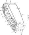
- Figure 1 is a preferred embodiment of the interbody device (also referred to as the implant) where the elongated members 20 are connected by two spanning components 30. One is adjacent a superior surface of the interbody device and the other is adjacent the inferior surface of the interbody device.
- This embodiment is designed to be inserted into the disc space in one configuration with the smooth walls 27 contacting the endplates, rotated into a second configuration where the top and bottom surfaces 21 contact the endplates, and then expanded in width to a third configuration where the smooth walls 27 are at a greater distance apart than they are in the second configuration.
- the distance between the smooth walls 27 is less than the distance between the top and bottom surfaces 21 so that when the implant is rotated from the first configuration into the second configuration it distracts the disc space.
- the spanning members are designed to deform during the width expansion so they have been made with deformation zones 31 and 32.
- the spanning components 30 fit into a recessed pocket 26 that is formed in the top or bottom surfaces 21 of the elongated members 20 when they are in their collapsed state.
- the top and bottom surfaces 21 are equipped with anti-migration teeth that allow for translation of the elongated members 20 during width expansion but help to prevent translation of the device along the longitudinal axis of the elongated members 20.
- the elongated members have angled surfaces 25 that form a tapered end for easier introduction into the disc space.
- two corners of the implant have been chamfered 24.
- a slot 23 and a rectangular end 22 are designed to mate with an insertion instrument.
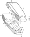
- Figure 2 shows the implant in the expanded configuration with the elongated elements 20 translated relative to one another and the spanning components 30 in their deformed states with deformation having occurred at deformation zones 31 and 32.
- the elongated elements 20 may be parallel with one another in the expanded configuration, or they may be transverse to one another. Also visible in Figure 2 is notch 28 which is designed to engage with the insertion instrument.
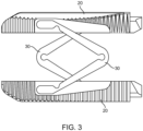
- Figure 3 is a top view of the implant in the expanded state with both elongated members and spanning components 30 clearly visible.
- the spanning components (also referred to herein as spanning members) 30 are positioned on opposite ends of one another and are configured in opposite directions for a uniform expansion. Therefore, in this embodiment one spanning component has first and second arms connected together with a hinge that opens up an forms an angle facing in one direction, and the other spanning component also has first and second arms that are connected together with a hinge that opens up and forms an angle facing in the opposite direction as the other spanning component.
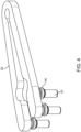
- Figure 4 shows the spanning components separate from the implant.
- Four engagement pins 33 and snap features 34 are designed to attach the spanning components 30 to the elongated members 20.
- Figure 5 shows a cross-section of the elongated member 20 where the attachment holes 29 that engage with the pins 33 and snap features 34 of the spanning members 30 are shown. Two pins on each arm of the spanning members are used in order to prevent unwanted pivoting at the connection point.
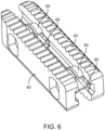
- Figure 6 shows an additional embodiment of the implant where the elongated members 40 are attached with two spanning members 50 that lock the elongated members 40 in their expanded configuration via mating geometry in the both the spanning members 50 and the elongated members 40 and a set of c-clips 60 as will be described below.
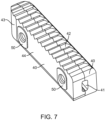
- Figure 7 shows the implant of Figure 6 in its collapsed state with a tapered end 43, smooth side walls 40, top and bottom surfaces 42, and an instrument engagement feature 41.
- the tapered end 43 facilitates insertion into the intervertebral space.
- Figure 8 a cross-section of Figure 7 taken through the spanning member 50 and this view shows the elongated members 40 with pockets 45 for the c-clips 60 and the spanning member with locking grooves 51.
- the c-clips 60 lock into the locking grooves 51 on the spanning members 50.
- the c-clips expand and contract such that when they move into the locking grooves they prevent motion.
- curved corners 46 that help facilitate the rotation from the first configuration to the second configuration.
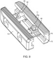
- Figure 9 shows another exemplary embodiment of the implant where the spanning components 80 and 90 telescope relative to each other to allow for greater translation of the elongated members 70.
- Figure 9 shows the device in its expanded state with smooth side walls 73, top and bottom surfaces 71, and instrument engagement feature 72.
- Figure 10 the embodiment of Figure 9 is shown from a top view in the expanded state.
- Slot 82 in the first spanning component 80 allows for the telescoping of the second spanning component 90.
- Snap feature 81 locks the first spanning component 80 and the second spanning component 90 relative to one another when in the expanded state.
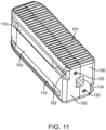
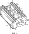
- Figure 11 shows an additional embodiment where the elongated members 100 have top and bottom surfaces 101 with a plurality of anti-migration teeth, smooth side walls 103, and instrument engagement features 104.
- the spanning components 110 consist of four ratcheting members. In the collapsed state the spanning components 110 are positioned in dovetailed slots 102 along the smooth side walls 103 in the elongated members 100. The slots 102 and the spanning components 110 have corresponding dovetail profiles to retain the spanning members 110 in their corresponding slot 102.
- the spanning members 110 are attached to the elongated members 100 via a series of pins 120 that traverse through both the elongated members 100 and the spanning components 110.
- Figure 12 shows the implant of Figure 11 in its expanded state.
- the ratchet teeth 111 on the spanning components 110 engage with the lock component 130 to fix the implant in its expanded position.
- the lock components 130 are attached to the elongated members 100 via the lock fixation pins 140 with the heads of the lock fixation pins being set in a recess 105 in the elongated members 100 when in the collapsed state.
- the spanning components 110 In order for the spanning components 110 to move from their position in the collapsed state into their position in the expanded state they will need to elastically deform during the time when they transition from being in the slots 102 in the elongated members 100 to being perpendicular to the smooth side walls 103 and spanning between the elongated members 100.
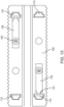
- Figure 13 shows a cross section of the implant in Figure 11 at the medial wall of the elongated member 100. Visible in this cross section are the spanning components 110, the lock 130, and the lock fixation pins 140. Also visible are the interaction between the locks 130 and the spanning members 110 at junction 131 where the lock ratchets along the ratchet teeth 111 in the spanning components 110.
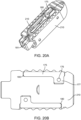
- Figures 20A-20E illustrate various features of other exemplary embodiments.
- Figure 20A is a perspective view of an exemplary embodiment of the interbody fusion device (also referred to as the implant) in the collapsed configuration.
- the implant includes two elongated members 210 that are attached with two spanning members 175 stacked on top of one another.
- the elongated members 210 include a relief cut 180 that is sized to receive the spanning components and alleviates loading of spanning components 175.
- Receptacle 181 is formed when the two elongate members are in the collapsed configuration and allow a surgical instrument to be coupled thereto, as will be discussed elsewhere in this specification.
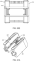
- Figure 20B illustrates a cross-section of Figure 20A taken through elongated member 210. This view illustrates how the spanning member 175 is coupled to the elongate member 210.
- the posts 177 on the spanning members 175 and cross pins 176 are designed to attach the spanning components 175 to the elongated members 210.
- the spanning member is seated in recess 180.
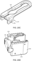
- FIG 20C is a perspective view illustrating the spanning member 175 more clearly.
- the spanning component 175 consists of two engagement posts 177 and two holes 178 to engage with pins 176.
- the spanning component is formed from two arms coupled together with a hinge that allows the arms to open or close. A relief cut in both arms allows the free end of the arms to pivot inwardly or outwardly thereby permitting the elongate members to remain substantially parallel with one another as they open up outward.
- Figure 20D illustrates the interbody fusion device in the expanded or distracted configuration with the spanning component also in the expanded configuration.
- An optional posterior cap 179 may be coupled to the elongated members 210 in order to lock the implant into the expanded configuration.
- a surgeon may use forceps or another surgical instrument to engage the posterior cap with the elongate members.
- the posterior cap may have a snap fit, press fit, or other coupling mechanism for attachment to the elongate members.
- the posterior cap also adds stability to the implant and also aids in containment of bone grafting material.
- Figure 20E is a rear view of the implant in Figure 20D and highlights the posterior cap 179.
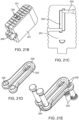
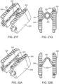
- Figures 21A-21G illustrate various aspects of other exemplary embodiments of the implant.
- Figure 21A is a perspective view of an interbody fusion device in the expanded configuration.
- the implant has two elongated members 201 that are attached with two spanning members 202.
- Spanning members 202 are disposed in a recessed pocket 203 that is formed in the center of the elongated members 201 when they are in their collapsed state.
- Spanning members 202 are attached to elongated members 201 via cross pins 204.
- Figure 21B illustrates the interbody fusion device of Figure 21A in the collapsed configuration.
- Receptacle 208 is formed when the elongate members 201 are collapsed. Receptacle 208 allows the implant to be coupled to other surgical instruments as will be discussed elsewhere.
- Figure 21C illustrates a cross-section of the embodiment in Figure 21A .
- the cross-section is taken through elongated member 201. This view highlights the engagement between elongated member 201, cross pins 204 and spanning components 202.
- Figure 21D illustrates a spanning component from the embodiment of Figure 21A .
- Two holes 205 are designed to fit cross pins 204 to attach to the implant.
- the spanning members are designed to deform at deformation zone 206 and pivot around cross pins 204 during width expansion.
- the cross member also referred to as a spanning member
- the cross member includes two arms coupled together with a hinge. The free end of each arm includes the hole 205 for receiving a pin.
- Figure 21E illustrates the orientation of the two spanning members 202 relative to one another in the embodiment of Figure 21A .
- the upper spanning member has an open end and a closed end facing in a first direction.
- the lower spanning member has an open end and a closed end facing in a second direction opposite the first direction.
- Pins 204 are also show in the holes of each spanning member.
- Figure 21F illustrates an alternative embodiment of the interbody fusion device of Figure 21A .
- the holes in the elongate member and the pins for each spanning member are disposed on the same side of the elongate member.
- one hole is on a superior surface of the implant and the second hole is on the inferior surface of the implant.
- the corresponding pins also are pressed in from opposite sides of the implant.
- One is pressed in from the superior surface and the other from the inferior surface.
- the second spanning member has one pin pressed in from each side of the elongate member.
- Figure 21G illustrates a top view of the embodiment in Figure 21F with the stagger pin configuration.
- Figures 22A-22D illustrate aspects of another exemplary embodiment of an interbody fusion device.
- Figure 22A illustrates a perspective view of the implant in the collapsed configuration.
- the elongated members 209 are attached with only one spanning member 202.
- Spanning member 202 fits into a recessed pocket 203 that is formed in the center of each of the elongated members 209 when they are in their collapsed state.
- Spanning member 202 is attached to the elongated members 201 via cross pins 204.
- Figure 22B illustrates a top view of the interbody fusion device in Figure 22A .
- Figure 22C shows a cross-section of the elongate member 201, showing the engagement between elongated member 209, cross pins 204 and spanning member 202.
- Figure 22D illustrates the spanning member 202 which includes two arms connected together with a hinge. The free ends of the arms include holes for receiving the pins 204.
- Figures 23A-23E illustrate features of another exemplary embodiment of an interbody fusion device.
- Figure 23A illustrates a perspective view of the interbody fusion device in the collapsed configuration.
- the elongated members 211 are coupled together with two spanning members 212.
- a receptacle 214 allows the implant to be engaged with a surgical instrument for delivery, as will be discussed elsewhere in this specification.
- the superior and inferior surfaces of the implant optionally have antimovement teeth, and this feature may optionally be included in any of the embodiments of implants disclosed herein.
- Figure 23B illustrates the implant of Figure 23A in the expanded configuration.
- Figure 23C shows a cross-section of the implant in Figure 23A in the expanded configuration. The cross-section is taken through spanning component 212.
- Cross pins 213 attach spanning components 212 to elongated members 211 and allow pivotal motion about the longitudinal axis of elongated members 211.
- FIG 23D illustrates the spanning member 212 in more detail.
- the spanning member 212 includes two arms connected together with a hinge. The free ends of the arms each have holes 216 for receiving cross pins 213 for securing the spanning member 212 to the elongate member.
- each arm has an arcuate cutout region which forms a secondary hinge 215. The secondary hinge allows the arm to further bend independently of the main hinge, such as in the case when the elongate members expand outward, they can remain in a substantially parallel configuration.
- Figure 23E illustrates both spanning members stacked on top of one another as they would be in the implant of Figure 23A with the cross-pins inserted in holes 216.
- a portion of both arms in each spanning member forms an angle with the main hinge, and the secondary hinge allows the free end of the arm to bend inward toward the opposite free end of an arm, thereby permitting the free ends of both arms to remain substantially parallel to one another. This allows the elongate members to also remain substantially parallel to one another in the expanded configuration.
- Figure 14 show a superior vertebral body 150, an inferior vertebral body 160, and the intervertebral space 180 between them.
- the superior articular process 161 of the inferior vertebral body 160 and the inferior articular process 151 of the superior vertebral body 150 have been removed on one side to allow for access into the intervertebral space as is common in a transforaminal interbody fusion procedure (TLIF).
- Figure 14 shows the implant 170 being inserted in to the intervertebral space 180 with the smooth side walls contacting the endplates of the vertebral bodies 150 and 160.
- the implant 170 may be any of the embodiments of implants disclosed herein.
- Figure 15 shows the implant rotated 90 degrees so that the top and bottom surfaces of the implant 172 are contacting the endplates of the vertebral bodies. Due to the difference in the height of the implant relative to the width of the implant this rotation results in the distraction of the vertebral bodies 150 and 160.
- Figure 16 shows the implant 170 in an expanded state creating a wider and more stable footprint for the implant and ample room for the insertion of graft material into the space created in the implant 173.
- the implant in this exemplary method of implantation may be any of those described herein.
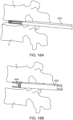
- Figures 18A-18F illustrate an exemplary method (not claimed) of delivering an interbody implant using an insertion guide device such as the one illustrated in Figure 17 .
- the insertion guide device 1802 is inserted into the intervertebral disc space between adjacent vertebrae V.
- the interbody implant 1804 is advanced distally out of the insertion guide device 1802 until it is exposed from the expandable portion of the insertion guide device and positioned in a desired location between the vertebrae, as illustrated in Figure 18C .
- the anti-migration teeth of the upper and lower surfaces of the implant face laterally and medially outward and the smooth lateral surfaces face upward and downward and engage the vertebral end plates.
- Figure 18D is similar to Figure 18C but illustrates a longer portion of the insertion guide device.
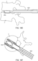
- FIG 18E the interbody implant and the insertion guide device have been rotated 90 degrees so that the textured surfaces of the interbody implant are in engagement with the endplates of the vertebrae and the smooth lateral surfaces of the implant now face laterally and medially outward.
- Figure 18F is a top view of the interbody implant and insertion guide device with the upper vertebra removed for ease in viewing. Additionally, the interbody implant has been laterally expanded to increase its width.
- the implant and the insertion guide device may be any of the embodiments disclosed herein.
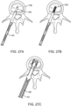
- Figures 27A-27C illustrate other aspects of implant delivery and deployment.
- Figure 27A shows a top view of an implant engaged with an insertion instrument 183 on an inferior vertebral body 198. The superior vertebrae has been omitted from the figure for convenience.
- the implant has been inserted into the intervertebral disc space with the smooth side walls 199 contacting the endplates.
- the insertion tool may be used to deliver the implant, or the insertion tool may be used in conjunction with the insertion guide previously described above.
- Figure 27B shows the implant rotated 90 degrees so that the top and bottom surfaces 200 of the implant are contacting the endplates of the vertebral bodies.
- the top and bottom surfaces preferably have anti-migration teeth to prevent unwanted movement. Rotation is accomplished by rotating the insertion tool.
- Figure 27C shows the interbody fusion device disengaged from the insertion tool and now engaged with the expansion instrument.
- the expansion instrument has been advanced distally thereby expanding the implant into the expanded configuration.
- the expansion instrument 187 and shims 181 are still coupled to the implant. After proper positioning and expansion have been confirmed, the expansion instrument and the shims may be removed.
- Figure 17 illustrates an interbody implant 1792 coupled to the insertion guide device 1794.
- the interbody implant is in its collapsed configuration, and it may be any of the embodiments disclosed herein.
- the insertion guide device may be any of the embodiments disclosed in this specification, or disclosed in US Patent Application No. 14/322,589 (Attorney Docket No. 44057-705.201) filed on July 2, 2014 Publication No. US2015-0080973 .
- the insertion guide device preferably includes a pair of elongate insertion plates with a resilient member disposed thereover. The implant is passed through a channel formed by the elongate insertion plates, the resilient member expands to accommodate the implant.
- Figures 19A-19B illustrate the pusher element which may be advanced or retracted by an operator to move the interbody implant through the insertion guide device previously described.
- the pusher element 1902 includes an elongate shaft with a handle on the proximal end for ease in manipulation.
- a lever 1904 helps lock the pusher to the interbody implant.
- Figure 19B illustrates the interbody implant 1906 coupled to the pusher element 1902.
- a leaf spring is disposed under the actuation lever thereby biasing the lever in the up position so that the pusher remains locked with the interbody implant. When the lever is moved, the implant may be decoupled from the pusher.
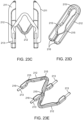
- Figures 24A-24C illustrate engagement of the interbody fusion device with a shim used to advance the implant along an insertion instrument.
- Figure 24A illustrates a perspective view of a shim used to engage any of the interbody fusion devices described herein.
- the shim 181 includes an elongate shaft having a mating feature 182 on a distal portion of the elongate shaft and that is configured to engage with any interbody fusion device, such as notch 28 as seen in Figure 2 , or any of the receptacles described herein, such as receptacle 214 in Figure 23A .
- the proximal end of the shim includes notches for engagement with an insertion tool.
- Figure 24B shows engagement of the shim 181 with any interbody fusion device disclosed herein.
- the mating feature 182 on the shim is releasably coupled with the corresponding notch, receptacle, or other mating feature on the implant.
- Figure 24C illustrates a cross-section in greater detail showing engagement of the shim 181 mating feature 182 with the implant.
- two shims 181 are illustrated.
- Shims 181 fit in slot 23 of the implant and engage with the implant in notch 28.
- the mating feature of the shim in this embodiment includes an enlarged head having an angled protrusion that is configured to be advanced forward into the implant and into the corresponding receptacle, but cannot easily be pulled out when the implant is in the collapsed configuration because the receptacle has a flat shoulder which engages the flat portion of the angled protrusion and prevents it from pulling out.
- Insertion instrument 183 includes an elongate shaft having a proximal end and distal end.
- a handle having a plurality of posts 185 extending radially outward forming a T-shaped handle is disposed on the proximal portion of the elongate shaft.
- the central portion of the shaft between the proximal and distal portions may be rectangular or square with cutouts passing through the wall of the shaft to lessen the weight of the device and also to permit an operator to see components passing through a central channel disposed in the shaft.
- Insertion instrument 183 consists of a slot 184 that allows for engagement with the shims previously describe above such as shims 181 in Figure 24A .
- the handle allows an operator to manipulate the insertion instrument, including rotating the instrument.
- Engagement feature 186 is configured to mate with the implant, such as rectangular end 22 in Figure 1 .
- Figure 25B illustrates the insertion instrument of Figure 25A engaged with an interbody fusion device such as any of those described herein.
- the shims are coupled to the implant and they are disposed in the central channel of the elongate shaft.
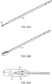
- Figures 26A-26E illustrate various features of several embodiments of an expansion tool used to expand the implant from the collapsed configuration to the expanded or distracted configuration.
- Figure 26A shows a perspective view of an expansion instrument 187.
- Expansion instrument 187 includes an elongate shaft having a proximal end and a distal end. Near the proximal end, slots 188 are configured to form a channel that engages the shims previously disclosed above.
- the elongate shaft includes a rectangular shaft 191 that may engage with a handle such as that seen in Figure 26B and used during expansion of the implant.
- Expansion instrument 187 has angled surfaces 189 that form a tapered end for easier introduction between the elongated members of the implant. Threaded component 190 allows for controlled expansion of the implant.
- Figure 26B illustrates a perspective view of a handle that may be used with the expansion instrument in Figure 26A .
- the handle includes a mating thread 193 to engage with threaded component 190, and rectangular slot 194 allows for translation of rectangular shaft 191 of expansion instrument 187 through the handle.
- Slot 196 allows for insertion of shim 181 and button 195 engages shim 181 with handle 192.
- Figure 26C illustrates a perspective view of the expansion instrument engaged with an implant. After the implant has been inserted into the intervertebral disc space, the insertion tool is removed, leaving the implant and shims in position. The shims and implant are then coupled to the expansion instrument as seen, and handle 192 and palm handle 197 are also attached to the expansion instrument. Figure 26C shows the implant once expansion is complete. Shims 181 are shown engaged with the implant, expansion instrument 187, and handle 192. Expansion instrument 187 is also shown engaged with handle 192 and palm handle 197. Actuation of palm handle 197 by pushing it forward or distally is used to drive expansion instrument 187 between the elongated members of the implant to cause expansion thereof.
- Figure 26D highlights the engagement of the shim, expansion instrument and implant and shows expansion of the implant into the expanded configuration.
- Figure 26E illustrates a perspective view of an alternative embodiment of another expansion instrument 207.
- Expansion instrument 207 has a slot 208 to translate around centrally located spanning members.
- Figures 28-32 more clearly illustrate use of the various instruments to insert and deploy the interbody implant.
- Figure 28 shows the removal of insertion instrument 183 from the implant after the implant has been rotated 90 degrees, leaving shims 181 attached to the implant.
- Figure 29 shows the engagement of shims 181 with expansion instrument 187 and expansion handle 192. Shims 181 slide through slots 188 of expansion instrument 187 and slots 196 of expansion handle 192 where button 195 locks shims 181 in place.
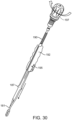
- Figure 30 shows the engagement of handle 197 via a quick-connect.
- Expansion instrument 187 slides towards the implant until threaded component 190 engages with expansion handle 192.
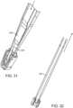
- Handle 197 is then used to drive expansion instrument 187 towards the implant, separating shims 181 and thereby separating the elongated members of the implant as shown in Figure 31 .
- the final position of the expansion instruments can be seen in Figure 26C .
- the expansion instruments can then be disengaged by driving component 190 away from the implant until threaded component 190 is no longer engaged with expansion handle 192.
- Pressing button 195 disengages shims 181, allowing the user to slide the expansion instruments away from the implant, leaving the expanded implant and shims 181 in place as shown in Figure 32 .
- Figure 31 shows expansion instrument 187 separating shims 181 and thereby separating the elongated members of the implant.
- Figure 32 shows shims 181 and the implant after expansion and after expansion instruments have been removed. Shims 181 can then be disengaged by pulling them away from the corresponding elongated member, leaving the implant in the expanded configuration.
Description
- The present invention generally relates to medical devices and more particularly relates to interbody devices. Interbody devices may be used for supporting and facilitating fusion of adjacent vertebrae in a patient's spine.
- Various interbody fusion devices such as fusion cages may be implanted in the intervertebral disc space. These devices facilitate fusion of the adjacent vertebrae together and support the adjacent vertebral bodies. Depending on the size of the interbody fusion device and the corresponding delivery instrument, a surgeon may have to remove bone in order to provide adequate space. Clearly, it would be desirable if bone removal could be minimized or eliminated all together. Moreover, adjacent tissue may also need to be retracted or removed, and it would be desirable to minimize or eliminate this as well. Also, insertion of the implant often requires distraction of the vertebrae, therefore it would be desirable to provide a low profile implant that minimizes the amount of distraction required.
- Newer interbody fusion devices are being developed which have a smaller more compact profile for delivery and a larger expanded profile after deployment. The smaller delivery size facilitates delivery, and the larger deployed configuration facilitates support and fusion of the bone. Therefore, it would be desirable to provide an interbody device that has an even smaller profile for delivery, and an even larger profile after implantation into the intervertebral disc space. At least some of these objectives will be satisfied by the devices and methods (not claimed) disclosed below.
- 2. Description of the Background Art. The following
US patents and patent publications are related to interbody devices: 2013/0103156 ;2012/0083887 ;2012/0083889 ;2012/0310350 ;8,317,866 ;7,870,905 ;6,395,031 ;6,833,066 ;7,655,042 ; and7,993,403 . -
US2012/0083887 describes a minimally invasive intervertebral implant which includes a circuitous body defining a luminal axis extending longitudinally therethrough. The circuitous body includes proximal and distal ends oppositely disposed along a lateral axis of the circuitous body Each of the proximal distal ends includes an aperture disposed therethrough such that the circuitous body includes a first configuration wherein the proximal and distal ends are at a maximum separation and a second configuration wherein the proximal and distal ends are closer together than in the first configuration. -
WO2012/135764 describes an articulating interbody cage in the form of an intervertebral device for use in the human spine. The device includes an interior end, a posterior end and at least four peripheral walls. The peripheral walls define an anterior volume surrounding a midline of the device and include a superior wall, an inferior wall and a pair of opposing walls, generally trapezoidal, shaped sidewalls. Each of the trapezoidalshaped sidewalls includes an internal hinge element that is rotatable from a first configuration to at least a second configuration such that the device is expandable in the first dimension. Each of the internal hinge elements include an axis that is coplanar with the midline of the device. - The present invention is set out in the appended claims. Disclosed herein are medical devices and interbody devices and methods of use (methods are not claimed). Interbody devices may be used for supporting and facilitating fusion of adjacent vertebrae in a patient's spine.
- In a first aspect of the present disclosure, an interbody implant for implanting in an intervertebral space surrounded by adjacent vertebral bodies in a patient during spinal fusion comprises one or more elongate members that form the implant. The one or more elongate members have superior and inferior surfaces with a height therebetween, and medial and lateral surfaces with a width therebetween. The superior and inferior surfaces are shaped to engage the vertebral bodies, and the height is set at a predetermined distance that is sized to fit into the intervertebral space. The width is set at a predetermined distance less than the predetermined height. The interbody implant has a first configuration, a second configuration, and a third configuration. The interbody implant is inserted into the intervertebral space in the first configuration such that medial and lateral surfaces contact the vertebral bodies. The interbody implant is actuated into the second configuration such that superior and inferior surfaces engage the vertebral bodies, and actuation of the implant from the first configuration to the second configuration distracts the vertebral bodies away from one another to increase the intervertebral space. The implant is actuated into the third configuration where the width of the implant is greater than width of the implant in the first or the second configuration.
- The second configuration may have the same width and height as the first configuration. The one or more elongate members may comprise two elongate members, and actuation of the implant from the second configuration to the third configuration may be obtained by translation of the two elongate members away from one another. The two elongate members are coupled together with two spanning components that deform between the second and the third configurations.
- The two elongate members are coupled together with two spanning components, and the two elongate members may translate along the spanning components. The spanning components may comprise a first spanning component and a second spanning component. The first spanning component faces in a first direction, and the second spanning component faces in a second direction opposite the first direction. The first spanning component may be disposed over the second spanning component. The spanning components may be at least partially disposed in a recessed region of the one or more elongate members. At least one of the one or more spanning components may comprise a first arm and a second arm. Each arm may have a free end and a hinged end. The hinged ends may be coupled together with a hinge. Each arm may further comprise a supplemental hinge disposed between the free end and the hinged end. The supplemental hinge may be configured to allow the free end to bend independently of the hinged end. At least one of the spanning components may comprise one or more apertures disposed in an arm of the spanning component. The one or more apertures may be sized to receive a pin.
- The spanning components may comprise a locking feature, and the two elongate members may lock into the third configuration when the two elongate members engage the locking feature. The spanning components may comprise a plurality of assembled components configured to telescope over one another thereby allowing the two elongate members to translate relative to one another. The one or more elongate members may comprise an engagement feature configured to allow the one or more elongate members to be releasably coupled to an insertion instrument, and the insertion instrument may be actuatable. Actuation of the insertion instrument may actuate the implant from the second configuration to the third configuration.
- The one or more elongate members may comprise a first elongate member and a second elongate member. The implant may further comprise a posterior cap that is engaged with the first and second elongate members and that is configured to hold the elongate members in the third configuration. At least some of the superior or inferior surfaces of the one or more elongate members may comprise anti-migration teeth.
- In another aspect of the present disclosure, an interbody implant for implanting in an intervertebral space surrounded by adjacent vertebral bodies in a patient during spinal fusion comprises a plurality of elongate members that form the implant, and spanning members that are coupled with the plurality of elongate members. The plurality of elongate members have superior and inferior surfaces with a height therebetween, and medial and lateral surfaces have a width therebetween. The superior and inferior surfaces are shaped to engage the vertebral bodies, and the height is set at a predetermined distance that is sized to fit into the intervertebral space. The width is set at a predetermined distance less than the predetermined height. The interbody implant has a first configuration, a second configuration, and a third configuration. The interbody implant is inserted into the intervertebral space in the first configuration such that medial and lateral surfaces contact the vertebral bodies, and the interbody implant is actuated into the second configuration such that the superior and inferior surfaces engage the vertebral bodies and distract the vertebral bodies away from one another. In the third configuration the width is greater than the width in the first or the second configuration, and actuation from the second configuration to the third configuration comprises translation of the one or more elongate members laterally away from one another.
- The plurality of elongate members may be coupled together with the spanning members and that may deform between the second and third configurations. The first spanning component may face in a first direction, and the second spanning component may face in a second direction opposite the first direction. The first spanning component may be disposed over the second spanning component. The spanning components may be at least partially disposed in a recessed region of the one or more elongate members. At least one of the spanning components may comprise a first arm and a second arm. Each arm may have a free end and a hinged end. The hinged ends are coupled together with a hinge. Each arm may also comprise a supplemental hinge disposed between the free end and the hinged end. The supplemental hinge may be configured to allow the free end to bend independently of the hinged end. At least one of the spanning components may comprise one or more apertures disposed in an arm of the spanning component, and the aperture may be sized to receive a pin. The spanning components may consist of only one spanning component.
- The plurality of elongate members may be coupled together with the spanning components, and the plurality of elongate members may translate along the spanning components. The spanning members may comprise locking features, and the plurality of elongate members may lock into the third configuration when the plurality of elongate members engage the locking features. The spanning members may comprise a plurality of assembled components configured to telescope over one another thereby allowing the plurality of elongate members to translate relative to one another. The plurality of elongate members may comprise an engagement feature configured to allow the plurality of elongate members to be releasably coupled to an insertion instrument. The insertion instrument may be actuatable and wherein actuation of the insertion instrument may actuate the implant from the second configuration to the third configuration.
- The plurality of elongate members may comprise a first elongate member and a second elongate member. The implant may further comprise a posterior cap that is engaged with the first and second elongate members and the cap may be configured to hold the elongate members in the third configuration. At least some of the superior or inferior surfaces of the plurality of elongate members comprise anti-migration teeth.
- In yet another aspect of the present disclosure, a method (not claimed) for delivering an interbody implant into an intervertebral space of a patient comprises inserting an interbody implant into the intervertebral space in a first configuration, actuating the interbody implant from the first configuration to a second configuration such that the interbody implant distracts the intervertebral space to a greater height when the interbody implant is in the second configuration, and actuating the interbody implant from the second configuration to a third configuration, wherein in the third configuration implant width increases relative to width of the implant in the first configuration.
- Actuating the interbody implant from the first configuration to the second configuration may comprise rotating the interbody implant in the intervertebral space. Actuating the interbody implant from the second configuration to the third configuration may comprise expanding two or more elongate members away from one another. Expanding the two or more elongate members may comprise expanding two elongate members away from one another and the two expanded elongate members may remain substantially parallel with one another after expansion. The method (not claimed) may further comprise locking the interbody implant in the third configuration. Locking the interbody implant may comprise engaging a cap against a posterior portion of the interbody implant. Actuating the interbody implant from the second configuration to the third configuration may comprise actuating an expansion instrument. The expansion instrument may comprise a wedged tip and actuating the interbody implant may comprise inserting the wedged tip into the interbody implant thereby causing expansion of the interbody implant. The interbody implant may be coupled to a delivery instrument and the method may further comprise releasing the interbody implant from the delivery instrument. The first configuration may comprise a collapsed configuration and inserting the interbody implant into the intervertebral space in the collapsed configuration may comprise coupling the interbody implant with an elongate shim, coupling the elongate shim with an insertion instrument, advancing the insertion instrument toward the intervertebral space, and disposing the interbody implant in the intervertebral space. Actuating the interbody implant from the first configuration to the second configuration may comprise rotating the insertion instrument thereby rotating the interbody implant. Actuating the interbody implant from the second configuration to the third configuration may comprise uncoupling the insertion instrument from the elongate shim, coupling an expansion instrument with the elongate shim, and advancing a wedged portion of the expansion instrument into the interbody implant thereby expanding the interbody implant.
- In still another aspect of the present disclosure, a system for delivering an interbody implant into an intervertebral space of a patient, comprises an interbody fusion device and an elongate shim having a proximal end and a distal end, wherein the distal end comprises an engagement element for releasably coupling the interbody fusion device. The proximal end is configured to engage a surgical instrument.
- The interbody fusion device may comprise a receptacle having a shoulder, and the engagement element comprises an angled protrusion with a flat shoulder, the angled protrusion configured to be advanced into the receptacle in the interbody fusion device and the flat shoulder of the engagement element engages the shoulder of the receptacle. The system may further comprise an insertion instrument having an elongate shaft with a central channel therethrough and a handle disposed on a proximal portion of the elongate shaft. The central channel may be sized to receive the elongate shim. The system may also comprise an expansion instrument having an elongate shaft and an expansion wedge near the distal portion of the elongate shaft. The expansion wedge may be configured to be advanced into the interbody fusion device thereby causing the interbody fusion device to expand. The expansion instrument may also have a proximal portion of the elongate shaft configured to be engaged with a handle.
- These and other embodiments are described in further detail in the following description related to the appended drawing figures.
- The novel features of the invention are set forth with particularity in the appended claims. A better understanding of the features and advantages of the present invention will be obtained by reference to the following detailed description that sets forth illustrative embodiments, in which the principles of the invention are utilized, and the accompanying drawings of which:
-
Figure 1 is a perspective view of an exemplary embodiment of an interbody fusion device in the collapsed configuration. -
Figure 2 is a perspective view of the embodiment inFigure 1 after it has been expanded. -
Figure 3 is a top view of the embodiment inFigure 2 . -
Figure 4 illustrates a spanning component from the embodiment ofFigure 1 . -
Figure 5 illustrates a partial cross-section of the interbody fusion device inFigure 1 . -
Figure 6 illustrates a perspective view of another exemplary embodiment of an interbody fusion device. -
Figure 7 illustrates the embodiment inFigure 6 while in the collapsed configuration. -
Figure 8 illustrates a partial cross-section through the embodiment ofFigure 6 . -
Figure 9 illustrates a perspective view of another exemplary embodiment of an interbody fusion device in the expanded configuration. -
Figure 10 is a top view of the embodiment inFigure 9 . -
Figure 11 illustrates still another exemplary embodiment of an interbody fusion device in the collapsed configuration. -
Figure 12 illustrates the embodiment ofFigure 11 in the expanded configuration. -
Figure 13 illustrates a partial cross-section of the embodiment inFigure 11 . -
Figure 14 illustrates an interbody fusion device disposed in the intervertebral disc space. -
Figure 15 illustrates the interbody fusion device inFigure 14 rotated 90 degrees. -
Figure 16 illustrates the interbody fusion device inFigure 15 in the expanded configuration. -
Figure 17 illustrates an interbody implant coupled to an insertion guide device. -
Figures 18A-18F illustrate insertion of the insertion guide device into the intervertebral disc space and delivery of an interbody implant. -
Figures 19A-19B illustrate a pusher element for pushing an interbody implant from the insertion guide device. -
Figures 20A-20E illustrate other features of exemplary embodiments of the interbody fusion device. -
Figures 21A-21G illustrate various aspects of other exemplary embodiments of the interbody fusion device. -
Figures 22A-22D illustrate aspects of another exemplary embodiment of an interbody fusion device. -
Figures 23A-23E illustrate features of still another exemplary embodiment of an interbody fusion device. -
Figures 24A-24C engagement of an interbody fusion device with a shim used to advance the implant with an insertion instrument. -
Figures 25A-25B illustrate a perspective view of an exemplary embodiment of an insertion tool. -
Figures 26A-26E illustrate various features of several embodiments of an expansion tool. -
Figures 27A-27C illustrate implantation of an interbody fusion device. -
Figure 28 illustrates a perspective view of the removal of the insertion instrument from the implant. -
Figure 29 illustrates a perspective view of the engagement of expansion instrument with the implant. -
Figure 30 illustrates a perspective view of the assembly inFigure 29 with handle engagement. -
Figure 31 illustrates a perspective view of the assembly inFigure 30 during expansion. -
Figure 32 illustrates a perspective view of the embodiment inFigure 30 after the expansion instrument has been removed. - Specific embodiments of the disclosed device and method of use (not claimed) will now be described with reference to the drawings. Nothing in this detailed description is intended to imply that any particular component, feature, or step is essential to the invention.
-
Figure 1 is a preferred embodiment of the interbody device (also referred to as the implant) where theelongated members 20 are connected by two spanningcomponents 30. One is adjacent a superior surface of the interbody device and the other is adjacent the inferior surface of the interbody device. This embodiment is designed to be inserted into the disc space in one configuration with thesmooth walls 27 contacting the endplates, rotated into a second configuration where the top andbottom surfaces 21 contact the endplates, and then expanded in width to a third configuration where thesmooth walls 27 are at a greater distance apart than they are in the second configuration. The distance between thesmooth walls 27 is less than the distance between the top andbottom surfaces 21 so that when the implant is rotated from the first configuration into the second configuration it distracts the disc space. In this embodiment of the implant, the spanning members are designed to deform during the width expansion so they have been made withdeformation zones components 30 fit into a recessedpocket 26 that is formed in the top orbottom surfaces 21 of theelongated members 20 when they are in their collapsed state. The top andbottom surfaces 21 are equipped with anti-migration teeth that allow for translation of theelongated members 20 during width expansion but help to prevent translation of the device along the longitudinal axis of theelongated members 20. The elongated members have angledsurfaces 25 that form a tapered end for easier introduction into the disc space. In order to aide in the rotation of the implant, two corners of the implant have been chamfered 24. In order to facilitate the insertion, rotation, and width expansion, of the implant, aslot 23 and arectangular end 22 are designed to mate with an insertion instrument. -
Figure 2 shows the implant in the expanded configuration with theelongated elements 20 translated relative to one another and the spanningcomponents 30 in their deformed states with deformation having occurred atdeformation zones elongated elements 20 may be parallel with one another in the expanded configuration, or they may be transverse to one another. Also visible inFigure 2 is notch 28 which is designed to engage with the insertion instrument. -
Figure 3 is a top view of the implant in the expanded state with both elongated members and spanningcomponents 30 clearly visible. The spanning components (also referred to herein as spanning members) 30 are positioned on opposite ends of one another and are configured in opposite directions for a uniform expansion. Therefore, in this embodiment one spanning component has first and second arms connected together with a hinge that opens up an forms an angle facing in one direction, and the other spanning component also has first and second arms that are connected together with a hinge that opens up and forms an angle facing in the opposite direction as the other spanning component. -
Figure 4 shows the spanning components separate from the implant. Four engagement pins 33 and snap features 34 are designed to attach the spanningcomponents 30 to theelongated members 20. -
Figure 5 shows a cross-section of theelongated member 20 where the attachment holes 29 that engage with thepins 33 and snap features 34 of the spanningmembers 30 are shown. Two pins on each arm of the spanning members are used in order to prevent unwanted pivoting at the connection point. -
Figure 6 shows an additional embodiment of the implant where theelongated members 40 are attached with two spanningmembers 50 that lock theelongated members 40 in their expanded configuration via mating geometry in the both the spanningmembers 50 and theelongated members 40 and a set of c-clips 60 as will be described below. -
Figure 7 shows the implant ofFigure 6 in its collapsed state with atapered end 43,smooth side walls 40, top andbottom surfaces 42, and aninstrument engagement feature 41. Thetapered end 43 facilitates insertion into the intervertebral space. - In
Figure 8 a cross-section ofFigure 7 taken through the spanningmember 50 and this view shows theelongated members 40 withpockets 45 for the c-clips 60 and the spanning member with lockinggrooves 51. In the expanded width the c-clips 60 lock into the lockinggrooves 51 on the spanningmembers 50. Thus, the c-clips expand and contract such that when they move into the locking grooves they prevent motion. Also visible inFigure 8 arecurved corners 46 that help facilitate the rotation from the first configuration to the second configuration. -
Figure 9 shows another exemplary embodiment of the implant where the spanningcomponents elongated members 70.Figure 9 shows the device in its expanded state withsmooth side walls 73, top andbottom surfaces 71, andinstrument engagement feature 72. - In
Figure 10 the embodiment ofFigure 9 is shown from a top view in the expanded state.Slot 82 in the first spanningcomponent 80 allows for the telescoping of the second spanningcomponent 90.Snap feature 81 locks the first spanningcomponent 80 and the second spanningcomponent 90 relative to one another when in the expanded state. -
Figure 11 shows an additional embodiment where theelongated members 100 have top andbottom surfaces 101 with a plurality of anti-migration teeth,smooth side walls 103, and instrument engagement features 104. In this embodiment of the interbody device, the spanningcomponents 110 consist of four ratcheting members. In the collapsed state the spanningcomponents 110 are positioned indovetailed slots 102 along thesmooth side walls 103 in theelongated members 100. Theslots 102 and the spanningcomponents 110 have corresponding dovetail profiles to retain the spanningmembers 110 in theircorresponding slot 102. The spanningmembers 110 are attached to theelongated members 100 via a series ofpins 120 that traverse through both theelongated members 100 and the spanningcomponents 110. -
Figure 12 shows the implant ofFigure 11 in its expanded state. Theratchet teeth 111 on the spanningcomponents 110 engage with thelock component 130 to fix the implant in its expanded position. Thelock components 130 are attached to theelongated members 100 via the lock fixation pins 140 with the heads of the lock fixation pins being set in arecess 105 in theelongated members 100 when in the collapsed state. In order for the spanningcomponents 110 to move from their position in the collapsed state into their position in the expanded state they will need to elastically deform during the time when they transition from being in theslots 102 in theelongated members 100 to being perpendicular to thesmooth side walls 103 and spanning between theelongated members 100. -
Figure 13 shows a cross section of the implant inFigure 11 at the medial wall of theelongated member 100. Visible in this cross section are the spanningcomponents 110, thelock 130, and the lock fixation pins 140. Also visible are the interaction between thelocks 130 and the spanningmembers 110 atjunction 131 where the lock ratchets along theratchet teeth 111 in the spanningcomponents 110. -
Figures 20A-20E illustrate various features of other exemplary embodiments.Figure 20A is a perspective view of an exemplary embodiment of the interbody fusion device (also referred to as the implant) in the collapsed configuration. The implant includes twoelongated members 210 that are attached with two spanningmembers 175 stacked on top of one another. Theelongated members 210 include arelief cut 180 that is sized to receive the spanning components and alleviates loading of spanningcomponents 175.Receptacle 181 is formed when the two elongate members are in the collapsed configuration and allow a surgical instrument to be coupled thereto, as will be discussed elsewhere in this specification. -
Figure 20B illustrates a cross-section ofFigure 20A taken through elongatedmember 210. This view illustrates how the spanningmember 175 is coupled to theelongate member 210. Theposts 177 on the spanningmembers 175 and crosspins 176 are designed to attach the spanningcomponents 175 to theelongated members 210. The spanning member is seated inrecess 180. -
Figure 20C is a perspective view illustrating the spanningmember 175 more clearly. The spanningcomponent 175 consists of twoengagement posts 177 and twoholes 178 to engage withpins 176. The spanning component is formed from two arms coupled together with a hinge that allows the arms to open or close. A relief cut in both arms allows the free end of the arms to pivot inwardly or outwardly thereby permitting the elongate members to remain substantially parallel with one another as they open up outward. -
Figure 20D illustrates the interbody fusion device in the expanded or distracted configuration with the spanning component also in the expanded configuration. Anoptional posterior cap 179 may be coupled to theelongated members 210 in order to lock the implant into the expanded configuration. A surgeon may use forceps or another surgical instrument to engage the posterior cap with the elongate members. The posterior cap may have a snap fit, press fit, or other coupling mechanism for attachment to the elongate members. In addition to locking the implant in the expanded configuration, the posterior cap also adds stability to the implant and also aids in containment of bone grafting material.Figure 20E is a rear view of the implant inFigure 20D and highlights theposterior cap 179. -
Figures 21A-21G illustrate various aspects of other exemplary embodiments of the implant.Figure 21A is a perspective view of an interbody fusion device in the expanded configuration. The implant has two elongatedmembers 201 that are attached with two spanningmembers 202. Spanningmembers 202 are disposed in a recessedpocket 203 that is formed in the center of theelongated members 201 when they are in their collapsed state. Spanningmembers 202 are attached toelongated members 201 via cross pins 204. -
Figure 21B illustrates the interbody fusion device ofFigure 21A in the collapsed configuration.Receptacle 208 is formed when theelongate members 201 are collapsed.Receptacle 208 allows the implant to be coupled to other surgical instruments as will be discussed elsewhere. -
Figure 21C illustrates a cross-section of the embodiment inFigure 21A . The cross-section is taken through elongatedmember 201. This view highlights the engagement betweenelongated member 201, cross pins 204 and spanningcomponents 202. -
Figure 21D illustrates a spanning component from the embodiment ofFigure 21A . Twoholes 205 are designed to fit cross pins 204 to attach to the implant. In this embodiment, the spanning members are designed to deform atdeformation zone 206 and pivot around crosspins 204 during width expansion. The cross member (also referred to as a spanning member) includes two arms coupled together with a hinge. The free end of each arm includes thehole 205 for receiving a pin. -
Figure 21E illustrates the orientation of the two spanningmembers 202 relative to one another in the embodiment ofFigure 21A . In this embodiment, the upper spanning member has an open end and a closed end facing in a first direction. The lower spanning member has an open end and a closed end facing in a second direction opposite the first direction.Pins 204 are also show in the holes of each spanning member. -
Figure 21F illustrates an alternative embodiment of the interbody fusion device ofFigure 21A . In the embodiment ofFigure 21A , the holes in the elongate member and the pins for each spanning member are disposed on the same side of the elongate member. InFigure 21F , one hole is on a superior surface of the implant and the second hole is on the inferior surface of the implant. Thus the corresponding pins also are pressed in from opposite sides of the implant. One is pressed in from the superior surface and the other from the inferior surface. Similarly, the second spanning member has one pin pressed in from each side of the elongate member. -
Figure 21G illustrates a top view of the embodiment inFigure 21F with the stagger pin configuration. -
Figures 22A-22D illustrate aspects of another exemplary embodiment of an interbody fusion device.Figure 22A illustrates a perspective view of the implant in the collapsed configuration. Here, theelongated members 209 are attached with only one spanningmember 202. Spanningmember 202 fits into a recessedpocket 203 that is formed in the center of each of theelongated members 209 when they are in their collapsed state. Spanningmember 202 is attached to theelongated members 201 via cross pins 204. -
Figure 22B illustrates a top view of the interbody fusion device inFigure 22A .Figure 22C shows a cross-section of theelongate member 201, showing the engagement betweenelongated member 209, cross pins 204 and spanningmember 202. -
Figure 22D illustrates the spanningmember 202 which includes two arms connected together with a hinge. The free ends of the arms include holes for receiving thepins 204. -
Figures 23A-23E illustrate features of another exemplary embodiment of an interbody fusion device.Figure 23A illustrates a perspective view of the interbody fusion device in the collapsed configuration. In this embodiment, theelongated members 211 are coupled together with two spanningmembers 212. Areceptacle 214 allows the implant to be engaged with a surgical instrument for delivery, as will be discussed elsewhere in this specification. The superior and inferior surfaces of the implant optionally have antimovement teeth, and this feature may optionally be included in any of the embodiments of implants disclosed herein. -
Figure 23B illustrates the implant ofFigure 23A in the expanded configuration.Figure 23C shows a cross-section of the implant inFigure 23A in the expanded configuration. The cross-section is taken through spanningcomponent 212. Cross pins 213 attach spanningcomponents 212 toelongated members 211 and allow pivotal motion about the longitudinal axis ofelongated members 211. -
Figure 23D illustrates the spanningmember 212 in more detail. The spanningmember 212 includes two arms connected together with a hinge. The free ends of the arms each haveholes 216 for receivingcross pins 213 for securing the spanningmember 212 to the elongate member. In addition the main hinge, each arm has an arcuate cutout region which forms asecondary hinge 215. The secondary hinge allows the arm to further bend independently of the main hinge, such as in the case when the elongate members expand outward, they can remain in a substantially parallel configuration. -
Figure 23E illustrates both spanning members stacked on top of one another as they would be in the implant ofFigure 23A with the cross-pins inserted inholes 216. A portion of both arms in each spanning member forms an angle with the main hinge, and the secondary hinge allows the free end of the arm to bend inward toward the opposite free end of an arm, thereby permitting the free ends of both arms to remain substantially parallel to one another. This allows the elongate members to also remain substantially parallel to one another in the expanded configuration. -
Figure 14 show a superiorvertebral body 150, an inferiorvertebral body 160, and theintervertebral space 180 between them. The superiorarticular process 161 of the inferiorvertebral body 160 and the inferiorarticular process 151 of the superiorvertebral body 150 have been removed on one side to allow for access into the intervertebral space as is common in a transforaminal interbody fusion procedure (TLIF).Figure 14 shows theimplant 170 being inserted in to theintervertebral space 180 with the smooth side walls contacting the endplates of thevertebral bodies implant 170 may be any of the embodiments of implants disclosed herein. -
Figure 15 shows the implant rotated 90 degrees so that the top and bottom surfaces of theimplant 172 are contacting the endplates of the vertebral bodies. Due to the difference in the height of the implant relative to the width of the implant this rotation results in the distraction of thevertebral bodies -
Figure 16 shows theimplant 170 in an expanded state creating a wider and more stable footprint for the implant and ample room for the insertion of graft material into the space created in theimplant 173. The implant in this exemplary method of implantation (not claimed) may be any of those described herein. -
Figures 18A-18F illustrate an exemplary method (not claimed) of delivering an interbody implant using an insertion guide device such as the one illustrated inFigure 17 . - In
Figure 18A , theinsertion guide device 1802 is inserted into the intervertebral disc space between adjacent vertebrae V. InFigure 18B , theinterbody implant 1804 is advanced distally out of theinsertion guide device 1802 until it is exposed from the expandable portion of the insertion guide device and positioned in a desired location between the vertebrae, as illustrated inFigure 18C . The anti-migration teeth of the upper and lower surfaces of the implant face laterally and medially outward and the smooth lateral surfaces face upward and downward and engage the vertebral end plates.Figure 18D is similar toFigure 18C but illustrates a longer portion of the insertion guide device. - In
Figure 18E , the interbody implant and the insertion guide device have been rotated 90 degrees so that the textured surfaces of the interbody implant are in engagement with the endplates of the vertebrae and the smooth lateral surfaces of the implant now face laterally and medially outward.Figure 18F is a top view of the interbody implant and insertion guide device with the upper vertebra removed for ease in viewing. Additionally, the interbody implant has been laterally expanded to increase its width. The implant and the insertion guide device may be any of the embodiments disclosed herein. -
Figures 27A-27C illustrate other aspects of implant delivery and deployment.Figure 27A shows a top view of an implant engaged with aninsertion instrument 183 on an inferiorvertebral body 198. The superior vertebrae has been omitted from the figure for convenience. The implant has been inserted into the intervertebral disc space with thesmooth side walls 199 contacting the endplates. The insertion tool may be used to deliver the implant, or the insertion tool may be used in conjunction with the insertion guide previously described above. -
Figure 27B shows the implant rotated 90 degrees so that the top andbottom surfaces 200 of the implant are contacting the endplates of the vertebral bodies. The top and bottom surfaces preferably have anti-migration teeth to prevent unwanted movement. Rotation is accomplished by rotating the insertion tool. -
Figure 27C shows the interbody fusion device disengaged from the insertion tool and now engaged with the expansion instrument. The expansion instrument has been advanced distally thereby expanding the implant into the expanded configuration. Theexpansion instrument 187 andshims 181 are still coupled to the implant. After proper positioning and expansion have been confirmed, the expansion instrument and the shims may be removed. -
Figure 17 illustrates aninterbody implant 1792 coupled to theinsertion guide device 1794. The interbody implant is in its collapsed configuration, and it may be any of the embodiments disclosed herein. The insertion guide device may be any of the embodiments disclosed in this specification, or disclosed inUS Patent Application No. 14/322,589 (Attorney Docket No. 44057-705.201) filed on July 2, 2014 US2015-0080973 . The insertion guide device preferably includes a pair of elongate insertion plates with a resilient member disposed thereover. The implant is passed through a channel formed by the elongate insertion plates, the resilient member expands to accommodate the implant. -
Figures 19A-19B illustrate the pusher element which may be advanced or retracted by an operator to move the interbody implant through the insertion guide device previously described. InFigure 19A , thepusher element 1902 includes an elongate shaft with a handle on the proximal end for ease in manipulation. Alever 1904 helps lock the pusher to the interbody implant.Figure 19B illustrates theinterbody implant 1906 coupled to thepusher element 1902. A leaf spring is disposed under the actuation lever thereby biasing the lever in the up position so that the pusher remains locked with the interbody implant. When the lever is moved, the implant may be decoupled from the pusher. -
Figures 24A-24C illustrate engagement of the interbody fusion device with a shim used to advance the implant along an insertion instrument.Figure 24A illustrates a perspective view of a shim used to engage any of the interbody fusion devices described herein. Theshim 181 includes an elongate shaft having amating feature 182 on a distal portion of the elongate shaft and that is configured to engage with any interbody fusion device, such asnotch 28 as seen inFigure 2 , or any of the receptacles described herein, such asreceptacle 214 inFigure 23A . The proximal end of the shim includes notches for engagement with an insertion tool. -
Figure 24B shows engagement of theshim 181 with any interbody fusion device disclosed herein. Themating feature 182 on the shim is releasably coupled with the corresponding notch, receptacle, or other mating feature on the implant. -
Figure 24C illustrates a cross-section in greater detail showing engagement of theshim 181mating feature 182 with the implant. Here twoshims 181 are illustrated.Shims 181 fit inslot 23 of the implant and engage with the implant innotch 28. The mating feature of the shim in this embodiment includes an enlarged head having an angled protrusion that is configured to be advanced forward into the implant and into the corresponding receptacle, but cannot easily be pulled out when the implant is in the collapsed configuration because the receptacle has a flat shoulder which engages the flat portion of the angled protrusion and prevents it from pulling out. -
Figures 25A-25B illustrate an exemplary embodiment of an insertion tool that may be used in conjunction with the shims previously described above to deliver any of the interbody fusion devices described herein to a treatment site.Insertion instrument 183 includes an elongate shaft having a proximal end and distal end. A handle having a plurality ofposts 185 extending radially outward forming a T-shaped handle is disposed on the proximal portion of the elongate shaft. The central portion of the shaft between the proximal and distal portions may be rectangular or square with cutouts passing through the wall of the shaft to lessen the weight of the device and also to permit an operator to see components passing through a central channel disposed in the shaft. The distal portion of the shaft may have a cylindrical portion.Insertion instrument 183 consists of aslot 184 that allows for engagement with the shims previously describe above such asshims 181 inFigure 24A . The handle allows an operator to manipulate the insertion instrument, including rotating the instrument.Engagement feature 186 is configured to mate with the implant, such asrectangular end 22 inFigure 1 . -
Figure 25B illustrates the insertion instrument ofFigure 25A engaged with an interbody fusion device such as any of those described herein. The shims are coupled to the implant and they are disposed in the central channel of the elongate shaft. -
Figures 26A-26E illustrate various features of several embodiments of an expansion tool used to expand the implant from the collapsed configuration to the expanded or distracted configuration.Figure 26A shows a perspective view of anexpansion instrument 187.Expansion instrument 187 includes an elongate shaft having a proximal end and a distal end. Near the proximal end,slots 188 are configured to form a channel that engages the shims previously disclosed above. The elongate shaft includes arectangular shaft 191 that may engage with a handle such as that seen inFigure 26B and used during expansion of the implant.Expansion instrument 187 has angledsurfaces 189 that form a tapered end for easier introduction between the elongated members of the implant. Threadedcomponent 190 allows for controlled expansion of the implant. -
Figure 26B illustrates a perspective view of a handle that may be used with the expansion instrument inFigure 26A . The handle includes amating thread 193 to engage with threadedcomponent 190, andrectangular slot 194 allows for translation ofrectangular shaft 191 ofexpansion instrument 187 through the handle.Slot 196 allows for insertion ofshim 181 andbutton 195 engagesshim 181 withhandle 192. -
Figure 26C illustrates a perspective view of the expansion instrument engaged with an implant. After the implant has been inserted into the intervertebral disc space, the insertion tool is removed, leaving the implant and shims in position. The shims and implant are then coupled to the expansion instrument as seen, and handle 192 and palm handle 197 are also attached to the expansion instrument.Figure 26C shows the implant once expansion is complete.Shims 181 are shown engaged with the implant,expansion instrument 187, and handle 192.Expansion instrument 187 is also shown engaged withhandle 192 andpalm handle 197. Actuation of palm handle 197 by pushing it forward or distally is used to driveexpansion instrument 187 between the elongated members of the implant to cause expansion thereof. -
Figure 26D highlights the engagement of the shim, expansion instrument and implant and shows expansion of the implant into the expanded configuration. -
Figure 26E illustrates a perspective view of an alternative embodiment of anotherexpansion instrument 207.Expansion instrument 207 has aslot 208 to translate around centrally located spanning members. -
Figures 28-32 more clearly illustrate use of the various instruments to insert and deploy the interbody implant.Figure 28 shows the removal ofinsertion instrument 183 from the implant after the implant has been rotated 90 degrees, leavingshims 181 attached to the implant. -
Figure 29 shows the engagement ofshims 181 withexpansion instrument 187 and expansion handle 192.Shims 181 slide throughslots 188 ofexpansion instrument 187 andslots 196 of expansion handle 192 wherebutton 195locks shims 181 in place. -
Figure 30 shows the engagement ofhandle 197 via a quick-connect.Expansion instrument 187 slides towards the implant until threadedcomponent 190 engages withexpansion handle 192. Handle 197 is then used to driveexpansion instrument 187 towards the implant, separatingshims 181 and thereby separating the elongated members of the implant as shown inFigure 31 . The final position of the expansion instruments can be seen inFigure 26C . The expansion instruments can then be disengaged by drivingcomponent 190 away from the implant until threadedcomponent 190 is no longer engaged withexpansion handle 192.Pressing button 195disengages shims 181, allowing the user to slide the expansion instruments away from the implant, leaving the expanded implant and shims 181 in place as shown inFigure 32 . -
Figure 31 showsexpansion instrument 187 separatingshims 181 and thereby separating the elongated members of the implant. -
Figure 32 showsshims 181 and the implant after expansion and after expansion instruments have been removed.Shims 181 can then be disengaged by pulling them away from the corresponding elongated member, leaving the implant in the expanded configuration. - While preferred embodiments of the present invention have been shown and described herein, it will be obvious to those skilled in the art that such embodiments are provided by way of example only. Numerous variations, changes, and substitutions will now occur to those skilled in the art without departing from the invention as set out in the the appended claims. It should be understood that various alternatives to the embodiments of the invention described herein may be employed in practicing the invention as set out in the appended claims. It is intended that the following claims define the scope of the invention and that methods and structures within the scope of these claims and their equivalents be covered thereby.
Claims (14)
- An interbody implant for implanting in an intervertebral space surrounded by adjacent vertebral bodies in a patient during spinal fusion, said implant comprising:a plurality of elongate members (20; 40; 70; 100; 210; 201; 209; 211) that form the implant, the plurality of elongate members having superior and inferior surfaces with a height therebetween, and medial and lateral surfaces having a width therebetween,wherein the superior and inferior surfaces are shaped to engage the vertebral bodies, andwherein the height is set at a predetermined distance that is sized to fit into the intervertebral space, andwherein the width is set at a predetermined distance less than the predetermined height, andwherein the interbody implant has a first configuration, a second configuration, and a third configuration,wherein the interbody implant is designedto be inserted into the intervertebral space in the first configuration such that medial and lateral surfaces contact the vertebral bodies,to be actuated from the first configuration into the second configuration such that superior and inferior surfaces engage the vertebral bodies, wherein actuation of the implant from the first configuration to the second configuration distracts the vertebral bodies away from one another to increase the intervertebral space, andto be actuated into the third configuration where the width of the implant is greater than width of the interbody implant in the first or the second configuration,wherein the plurality of elongate members (20; 40; 70; 100; 210; 201; 209; 211) is coupled together with a first spanning component (30; 50; 80; 110; 175; 202; 212) that faces in a first direction and a second spanning component (30; 50; 90; 110; 175; 202; 212) that faces in a second direction opposite the first direction.
- The implant of claim 1, wherein the second configuration has the same width and height as the first configuration.
- The implant of claim 1, wherein the plurality of elongate members comprises two elongate members (20; 40; 70; 100; 210; 201; 209; 211), and
wherein actuation of the implant from the second configuration to the third configuration is obtained by translation of the two elongate members (20; 40; 70; 100; 210; 201; 209; 211) away from one another. - The implant of claim 2, wherein the plurality of elongate members (20; 210) comprises two elongate members and the spanning components (30; 175) are arranged to deform between the second and the third configurations.
- The implant of claim 4, wherein the spanning components (30; 175) are at least partially disposed in a recessed region (26; 180) of the elongate members (20; 210).
- The implant of claim 4, wherein at least one of the spanning components (212) comprises a first arm and a second arm, each arm having a free end and a hinged end, the hinged ends coupled together with a hinge.
- The implant of claim 6, wherein each arm further comprises a supplemental hinge (215) disposed between the free end and the hinged end, the supplemental hinge configured to allow the free end to bend independently of the hinged end.
- The implant of claim 4, wherein at least one of the spanning components comprises one or more apertures disposed in an arm of the spanning component, the aperture sized to receive a pin.
- The implant of claim 2, wherein the plurality of elongate members comprises two elongate members and the two elongate members are arranged to translate along the spanning components.
- The implant of claim 9, wherein the spanning components (50) comprise a locking feature, and wherein the two elongate members (40) lock into the third configuration when the two elongate members (40) engage the locking feature.
- The implant of claim 9, wherein the spanning components (80; 90) comprise a plurality of assembled components configured to telescope over one another thereby allowing the two elongate members (70) to translate relative to one another.
- The implant of claim 2, wherein the plurality of elongate members (40) comprise an engagement feature (41) configured to allow the elongate members to be releasably coupled to an insertion instrument, wherein the insertion instrument is actuatable and wherein actuation of the insertion instrument actuates the implant from the second configuration to the third configuration.
- The implant of claim 1, wherein the plurality of elongate members comprise a first elongate member and a second elongate member, the implant further comprising a posterior cap (179) engaged with the first and second elongate members (210) and configured to hold the elongate members in the third configuration.
- The implant of claim 1, wherein at least some of the superior or inferior surfaces of the plurality of elongate members (20; 40; 70; 100; 210; 201; 209; 211) comprise antimigration teeth.
Applications Claiming Priority (3)
| Application Number | Priority Date | Filing Date | Title |
|---|---|---|---|
| US201361842888P | 2013-07-03 | 2013-07-03 | |
| US14/322,702 US10265192B2 (en) | 2013-07-03 | 2014-07-02 | Methods and apparatus for implanting an interbody device |
| PCT/US2014/045490 WO2015003173A2 (en) | 2013-07-03 | 2014-07-03 | Methods and apparatus for implanting an interbody device |
Publications (4)
| Publication Number | Publication Date |
|---|---|
| EP3016617A2 EP3016617A2 (en) | 2016-05-11 |
| EP3016617A4 EP3016617A4 (en) | 2017-05-03 |
| EP3016617C0 EP3016617C0 (en) | 2023-10-11 |
| EP3016617B1 true EP3016617B1 (en) | 2023-10-11 |
Family
ID=52133344
Family Applications (1)
| Application Number | Title | Priority Date | Filing Date |
|---|---|---|---|
| EP14819704.9A Active EP3016617B1 (en) | 2013-07-03 | 2014-07-03 | Apparatus for implanting an interbody device |
Country Status (4)
| Country | Link |
|---|---|
| US (3) | US10265192B2 (en) |
| EP (1) | EP3016617B1 (en) |
| JP (3) | JP2016526455A (en) |
| WO (1) | WO2015003173A2 (en) |
Families Citing this family (77)
| Publication number | Priority date | Publication date | Assignee | Title |
|---|---|---|---|---|
| US8105382B2 (en) | 2006-12-07 | 2012-01-31 | Interventional Spine, Inc. | Intervertebral implant |
| US8900307B2 (en) | 2007-06-26 | 2014-12-02 | DePuy Synthes Products, LLC | Highly lordosed fusion cage |
| WO2009092102A1 (en) | 2008-01-17 | 2009-07-23 | Synthes Usa, Llc | An expandable intervertebral implant and associated method of manufacturing the same |
| EP2262449B1 (en) | 2008-04-05 | 2020-03-11 | Synthes GmbH | Expandable intervertebral implant |
| US9724140B2 (en) | 2010-06-02 | 2017-08-08 | Wright Medical Technology, Inc. | Tapered, cylindrical cruciform hammer toe implant and method |
| US8608785B2 (en) | 2010-06-02 | 2013-12-17 | Wright Medical Technology, Inc. | Hammer toe implant with expansion portion for retrograde approach |
| US9498273B2 (en) | 2010-06-02 | 2016-11-22 | Wright Medical Technology, Inc. | Orthopedic implant kit |
| DE102010047901B4 (en) * | 2010-10-11 | 2019-01-10 | Heinrich Böhm | Implant for the spine and operating instrument |
| US9308099B2 (en) | 2011-02-14 | 2016-04-12 | Imds Llc | Expandable intervertebral implants and instruments |
| US9393126B2 (en) * | 2012-04-20 | 2016-07-19 | Peter L. Mayer | Bilaterally placed disc prosthesis for spinal implant and method of bilateral placement |
| US9364339B2 (en) * | 2012-04-30 | 2016-06-14 | Peter L. Mayer | Unilaterally placed expansile spinal prosthesis |
| BR112014029904A2 (en) * | 2012-05-29 | 2017-06-27 | Nlt Spine Ltd | laterally deflectable implant, assembly and method for implantation into a body |
| US8663332B1 (en) | 2012-12-13 | 2014-03-04 | Ouroboros Medical, Inc. | Bone graft distribution system |
| US8945232B2 (en) | 2012-12-31 | 2015-02-03 | Wright Medical Technology, Inc. | Ball and socket implants for correction of hammer toes and claw toes |
| US9522070B2 (en) | 2013-03-07 | 2016-12-20 | Interventional Spine, Inc. | Intervertebral implant |
| US10369010B2 (en) | 2013-03-15 | 2019-08-06 | Spectrum Spine Ip Holdings, Llc | Expandable inter-body fusion devices and methods |
| US9333093B2 (en) * | 2013-05-13 | 2016-05-10 | Kamran Aflatoon | Minimally invasive expandable interbody fusion cage |
| EP2999438B1 (en) | 2013-05-20 | 2022-05-18 | K2M, Inc. | Adjustable implant and insertion tool |
| US9788971B1 (en) | 2013-05-22 | 2017-10-17 | Nuvasive, Inc. | Expandable fusion implant and related methods |
| US9408721B2 (en) | 2013-07-03 | 2016-08-09 | Spine Innovation, Llc | Methods and apparatus for an insertion guide device |
| US10265192B2 (en) | 2013-07-03 | 2019-04-23 | Spine Innovation, Llc | Methods and apparatus for implanting an interbody device |
| US9186259B2 (en) | 2013-09-09 | 2015-11-17 | Ouroboros Medical, Inc. | Expandable trials |
| US9724139B2 (en) | 2013-10-01 | 2017-08-08 | Wright Medical Technology, Inc. | Hammer toe implant and method |
| US9474561B2 (en) | 2013-11-19 | 2016-10-25 | Wright Medical Technology, Inc. | Two-wire technique for installing hammertoe implant |
| US9545283B2 (en) * | 2013-12-23 | 2017-01-17 | Jmea Corporation | Devices and methods for preparation of vertebral members |
| US9730802B1 (en) | 2014-01-14 | 2017-08-15 | Nuvasive, Inc. | Spinal fusion implant and related methods |
| US9545274B2 (en) * | 2014-02-12 | 2017-01-17 | Wright Medical Technology, Inc. | Intramedullary implant, system, and method for inserting an implant into a bone |
| US9498266B2 (en) | 2014-02-12 | 2016-11-22 | Wright Medical Technology, Inc. | Intramedullary implant, system, and method for inserting an implant into a bone |
| AU2014331633B2 (en) | 2014-09-18 | 2017-06-22 | Wright Medical Technology, Inc | Hammertoe implant and instrument |
| US9585762B2 (en) | 2014-10-09 | 2017-03-07 | K2M, Inc. | Expandable spinal interbody spacer and method of use |
| US10080597B2 (en) | 2014-12-19 | 2018-09-25 | Wright Medical Technology, Inc. | Intramedullary anchor for interphalangeal arthrodesis |
| US9060876B1 (en) | 2015-01-20 | 2015-06-23 | Ouroboros Medical, Inc. | Stabilized intervertebral scaffolding systems |
| US11426290B2 (en) * | 2015-03-06 | 2022-08-30 | DePuy Synthes Products, Inc. | Expandable intervertebral implant, system, kit and method |
| WO2016183382A1 (en) | 2015-05-12 | 2016-11-17 | Nuvasive, Inc. | Expandable lordosis intervertebral implants |
| US9814602B2 (en) * | 2015-05-14 | 2017-11-14 | Globus Medical, Inc. | Expandable intervertebral implants and methods of installation thereof |
| WO2017035155A1 (en) | 2015-08-25 | 2017-03-02 | Imds Llc | Expandable intervertebral implants |
| AU2016381191B2 (en) | 2015-12-30 | 2021-05-20 | Nuvasive, Inc. | Lordotic expandable fusion implant |
| US10004608B2 (en) * | 2016-02-26 | 2018-06-26 | K2M, Inc. | Insertion instrument for expandable spinal implants |
| US11253369B2 (en) * | 2016-03-14 | 2022-02-22 | Wiltrom Co., Ltd. | Spinal implant structure and kit thereof |
| TWI589266B (en) * | 2016-03-14 | 2017-07-01 | 曾昌和 | Spinal implant structure and kit thereof |
| EP3222251B1 (en) * | 2016-03-21 | 2018-12-05 | 41Medical AG | Expandable spinal implant |
| JP6995789B2 (en) | 2016-06-28 | 2022-01-17 | イーアイティー・エマージング・インプラント・テクノロジーズ・ゲーエムベーハー | Expandable and angle adjustable intervertebral cage |
| CN109688980B (en) | 2016-06-28 | 2022-06-10 | Eit 新兴移植技术股份有限公司 | Expandable and angularly adjustable intervertebral cage with articulation joint |
| US10052215B2 (en) * | 2016-06-29 | 2018-08-21 | Globus Medical, Inc. | Expandable fusion device and method of installation thereof |
| WO2018015964A1 (en) * | 2016-07-21 | 2018-01-25 | Nlt Spine Ltd. | Expandable implant |
| US9883953B1 (en) | 2016-09-21 | 2018-02-06 | Integrity Implants Inc. | Stabilized laterovertically-expanding fusion cage systems with tensioner |
| US10314718B2 (en) * | 2016-09-22 | 2019-06-11 | Loubert S. Suddaby | Expandable intervertebral fusion implant |
| JP7082122B2 (en) | 2016-10-25 | 2022-06-07 | アンプリファイ サージカル インコーポレイテッド | Methods and instruments for intervertebral cage dilation |
| FR3058043B1 (en) * | 2016-10-27 | 2020-11-13 | Ldr Medical | EXPANDABLE INTERSOMATIC CAGE |
| FR3058044A1 (en) * | 2016-10-27 | 2018-05-04 | Ldr Medical | EXPANDABLE INTERSOMATIC CAGE |
| US10537436B2 (en) | 2016-11-01 | 2020-01-21 | DePuy Synthes Products, Inc. | Curved expandable cage |
| US10888433B2 (en) | 2016-12-14 | 2021-01-12 | DePuy Synthes Products, Inc. | Intervertebral implant inserter and related methods |
| EP3568109A4 (en) | 2017-01-10 | 2020-09-16 | Integrity Implants Inc. | Expandable intervertebral fusion device |
| US11701239B2 (en) | 2017-01-26 | 2023-07-18 | Loubert S. Suddaby | Stand-alone expandable interbody spinal fusion device with integrated fixation mechanism |
| US11207192B2 (en) | 2017-01-26 | 2021-12-28 | Loubert S. Suddaby | Stand-alone expandable interbody spinal fusion device with integrated fixation mechanism |
| US10398563B2 (en) | 2017-05-08 | 2019-09-03 | Medos International Sarl | Expandable cage |
| US11344424B2 (en) | 2017-06-14 | 2022-05-31 | Medos International Sarl | Expandable intervertebral implant and related methods |
| US10940016B2 (en) | 2017-07-05 | 2021-03-09 | Medos International Sarl | Expandable intervertebral fusion cage |
| WO2019023251A1 (en) | 2017-07-24 | 2019-01-31 | Integrity Implants, Inc. | Surgical implant and related methods |
| US10596010B2 (en) | 2017-09-18 | 2020-03-24 | Loubert S. Suddaby | Stand-alone expandable interbody spinal fusion device with locking mechanism |
| US11219532B2 (en) | 2017-09-18 | 2022-01-11 | Loubert S. Suddaby | Stand-alone expandable interbody spinal fusion device with locking mechanism |
| WO2019126213A1 (en) | 2017-12-18 | 2019-06-27 | Nuvasive, Inc. | Expandable implant device |
| US10945859B2 (en) | 2018-01-29 | 2021-03-16 | Amplify Surgical, Inc. | Expanding fusion cages |
| CN108125736A (en) * | 2018-02-09 | 2018-06-08 | 申才良 | A kind of spliced homogeneous allogenic bone fusion device |
| CN111989056A (en) | 2018-03-01 | 2020-11-24 | 正诚植入公司 | Expandable fusion device with independent expansion system |
| US11446156B2 (en) | 2018-10-25 | 2022-09-20 | Medos International Sarl | Expandable intervertebral implant, inserter instrument, and related methods |
| US20220142165A1 (en) | 2019-03-15 | 2022-05-12 | Nippon Soda Co., Ltd. | Heterocyclic compound and agricultural or horticultural fungicide |
| US11026805B2 (en) | 2019-07-30 | 2021-06-08 | Loubert S. Suddaby | Expandable intervertebral fusion implant |
| US11678906B2 (en) | 2019-09-09 | 2023-06-20 | Amplify Surgical, Inc. | Multi-portal surgical systems, cannulas, and related technologies |
| US11464648B2 (en) | 2019-09-09 | 2022-10-11 | Amplify Surgical, Inc. | Multi-portal surgical systems |
| TWI720677B (en) * | 2019-11-05 | 2021-03-01 | 台灣微創醫療器材股份有限公司 | Spinal implant structure |
| US11166826B2 (en) * | 2019-11-13 | 2021-11-09 | Ossaware Biotech Co., Ltd. | Multi-section expandable device |
| US11426286B2 (en) | 2020-03-06 | 2022-08-30 | Eit Emerging Implant Technologies Gmbh | Expandable intervertebral implant |
| US11850160B2 (en) | 2021-03-26 | 2023-12-26 | Medos International Sarl | Expandable lordotic intervertebral fusion cage |
| US11752009B2 (en) | 2021-04-06 | 2023-09-12 | Medos International Sarl | Expandable intervertebral fusion cage |
| KR102511113B1 (en) * | 2022-04-08 | 2023-03-15 | 김현성 | Bidirectional expandable intervertebral fusion cage device |
| US11950770B1 (en) | 2022-12-01 | 2024-04-09 | Amplify Surgical, Inc. | Multi-portal split cannulas, endoscopic hemostatic dispensers and surgical tools |
Family Cites Families (23)
| Publication number | Priority date | Publication date | Assignee | Title |
|---|---|---|---|---|
| US6039761A (en) * | 1997-02-12 | 2000-03-21 | Li Medical Technologies, Inc. | Intervertebral spacer and tool and method for emplacement thereof |
| US6193757B1 (en) | 1998-10-29 | 2001-02-27 | Sdgi Holdings, Inc. | Expandable intervertebral spacers |
| DE10012461A1 (en) | 2000-03-15 | 2001-09-20 | Mahle Filtersysteme Gmbh | Oil filter for cleaning lubricating oil has annular filter insert separating clean side from input side |
| WO2003094699A2 (en) * | 2002-05-08 | 2003-11-20 | Stephen Ritland | Dynamic fixation device and method of use |
| WO2006034436A2 (en) | 2004-09-21 | 2006-03-30 | Stout Medical Group, L.P. | Expandable support device and method of use |
| US7441599B2 (en) | 2005-11-18 | 2008-10-28 | Chevron U.S.A. Inc. | Controlling the pressure within an annular volume of a wellbore |
| US20080114367A1 (en) * | 2006-11-10 | 2008-05-15 | Syberspine Limited | Method and relaxable distracters for in-situ formation of intervertebral disc prosthesis |
| WO2009092102A1 (en) | 2008-01-17 | 2009-07-23 | Synthes Usa, Llc | An expandable intervertebral implant and associated method of manufacturing the same |
| US20100145455A1 (en) | 2008-12-10 | 2010-06-10 | Innvotec Surgical, Inc. | Lockable spinal implant |
| US8623056B2 (en) | 2008-10-23 | 2014-01-07 | Linares Medical Devices, Llc | Support insert associated with spinal vertebrae |
| WO2010078520A2 (en) * | 2008-12-31 | 2010-07-08 | Jimenez, Omar, F. | Flexible joint arrangement incorporating flexure members |
| US8506635B2 (en) | 2010-06-02 | 2013-08-13 | Warsaw Orthopedic, Inc. | System and methods for a laterally expanding implant |
| JP4817155B1 (en) | 2010-08-30 | 2011-11-16 | Necインフロンティア株式会社 | Printer |
| EP2624773B1 (en) | 2010-10-05 | 2022-06-01 | EIT Emerging Implant Technologies GmbH | Minimally invasive intervertebral system |
| US9408710B2 (en) | 2010-10-05 | 2016-08-09 | Morgan Packard Lorio | Intervertebral device and methods of use |
| WO2012112596A1 (en) | 2011-02-14 | 2012-08-23 | Imds Corporation | Expandable intervertebral implants |
| JP6223958B2 (en) | 2011-03-30 | 2017-11-01 | トリニティ・オーソペディックス・リミテッド・ライアビリティ・カンパニーTrinity Orthopedics Llc | Intervertebral device |
| US8685095B2 (en) | 2011-04-19 | 2014-04-01 | Warsaw Orthopedic, Inc. | Expandable implant system and methods of use |
| US9066813B2 (en) | 2011-06-03 | 2015-06-30 | Biomet Spine, Llc | Unidirectional dynamic interbody fusion device and method of use |
| US9439771B2 (en) | 2011-10-19 | 2016-09-13 | P&H Medical Products, Llc | Laterally expandable spinal prosthesis |
| US9271777B2 (en) | 2011-12-14 | 2016-03-01 | Biomet Spine, Llc | Unilateral moveable interbody fusion device and method of use |
| US9408721B2 (en) | 2013-07-03 | 2016-08-09 | Spine Innovation, Llc | Methods and apparatus for an insertion guide device |
| US10265192B2 (en) | 2013-07-03 | 2019-04-23 | Spine Innovation, Llc | Methods and apparatus for implanting an interbody device |
-
2014
- 2014-07-02 US US14/322,702 patent/US10265192B2/en active Active
- 2014-07-03 WO PCT/US2014/045490 patent/WO2015003173A2/en active Application Filing
- 2014-07-03 JP JP2016524386A patent/JP2016526455A/en active Pending
- 2014-07-03 EP EP14819704.9A patent/EP3016617B1/en active Active
-
2018
- 2018-06-06 US US16/001,917 patent/US10512551B2/en active Active
- 2018-12-27 JP JP2018244110A patent/JP2019048196A/en active Pending
-
2019
- 2019-11-08 US US16/678,392 patent/US11491026B2/en active Active
-
2020
- 2020-07-07 JP JP2020117036A patent/JP2020168463A/en active Pending
Also Published As
| Publication number | Publication date |
|---|---|
| EP3016617A2 (en) | 2016-05-11 |
| JP2016526455A (en) | 2016-09-05 |
| EP3016617C0 (en) | 2023-10-11 |
| WO2015003173A2 (en) | 2015-01-08 |
| WO2015003173A3 (en) | 2015-04-16 |
| US10512551B2 (en) | 2019-12-24 |
| US20180280153A1 (en) | 2018-10-04 |
| US20150012098A1 (en) | 2015-01-08 |
| US20200069435A1 (en) | 2020-03-05 |
| JP2020168463A (en) | 2020-10-15 |
| JP2019048196A (en) | 2019-03-28 |
| EP3016617A4 (en) | 2017-05-03 |
| US10265192B2 (en) | 2019-04-23 |
| US11491026B2 (en) | 2022-11-08 |
Similar Documents
| Publication | Publication Date | Title |
|---|---|---|
| US11491026B2 (en) | Methods and apparatus for implanting an interbody device | |
| US8663330B2 (en) | Expandable vertebral device with ring plate | |
| US10092422B2 (en) | Bone fusion device, apparatus and method | |
| JP6643364B2 (en) | Interbody fusion device and system for implantation | |
| EP2830542B1 (en) | Expandable intervertebral implant | |
| US8894711B2 (en) | Expandable intervertebral implant and associated surgical method | |
| US8894712B2 (en) | Expandable intervertebral implant and associated surgical method | |
| US8876829B2 (en) | Adjustable apparatus and methods for inserting an implant | |
| US20190125327A1 (en) | Configurable Intervertebral Implant | |
| US9913732B2 (en) | Interbody fusion device with separable retention component for lateral approach and associated methods | |
| US20070093897A1 (en) | System and method for fusion cage implantation | |
| US20100179656A1 (en) | Expandable cage with locking device | |
| JP2024500784A (en) | Tethered intervertebral implant |
Legal Events
| Date | Code | Title | Description |
|---|---|---|---|
| PUAI | Public reference made under article 153(3) epc to a published international application that has entered the european phase |
Free format text: ORIGINAL CODE: 0009012 |
|
| STAA | Information on the status of an ep patent application or granted ep patent |
Free format text: STATUS: REQUEST FOR EXAMINATION WAS MADE |
|
| 17P | Request for examination filed |
Effective date: 20160107 |
|
| AK | Designated contracting states |
Kind code of ref document: A2 Designated state(s): AL AT BE BG CH CY CZ DE DK EE ES FI FR GB GR HR HU IE IS IT LI LT LU LV MC MK MT NL NO PL PT RO RS SE SI SK SM TR |
|
| AX | Request for extension of the european patent |
Extension state: BA ME |
|
| DAX | Request for extension of the european patent (deleted) | ||
| A4 | Supplementary search report drawn up and despatched |
Effective date: 20170405 |
|
| RIC1 | Information provided on ipc code assigned before grant |
Ipc: A61F 2/30 20060101ALI20170330BHEP Ipc: A61F 2/44 20060101AFI20170330BHEP Ipc: A61F 2/46 20060101ALI20170330BHEP |
|
| GRAP | Despatch of communication of intention to grant a patent |
Free format text: ORIGINAL CODE: EPIDOSNIGR1 |
|
| STAA | Information on the status of an ep patent application or granted ep patent |
Free format text: STATUS: GRANT OF PATENT IS INTENDED |
|
| INTG | Intention to grant announced |
Effective date: 20230502 |
|
| GRAS | Grant fee paid |
Free format text: ORIGINAL CODE: EPIDOSNIGR3 |
|
| GRAA | (expected) grant |
Free format text: ORIGINAL CODE: 0009210 |
|
| STAA | Information on the status of an ep patent application or granted ep patent |
Free format text: STATUS: THE PATENT HAS BEEN GRANTED |
|
| AK | Designated contracting states |
Kind code of ref document: B1 Designated state(s): AL AT BE BG CH CY CZ DE DK EE ES FI FR GB GR HR HU IE IS IT LI LT LU LV MC MK MT NL NO PL PT RO RS SE SI SK SM TR |
|
| RAP3 | Party data changed (applicant data changed or rights of an application transferred) |
Owner name: SPINE INNOVATION, LLC |
|
| REG | Reference to a national code |
Ref country code: GB Ref legal event code: FG4D |
|
| REG | Reference to a national code |
Ref country code: CH Ref legal event code: EP |
|
| REG | Reference to a national code |
Ref country code: DE Ref legal event code: R096 Ref document number: 602014088572 Country of ref document: DE |
|
| REG | Reference to a national code |
Ref country code: IE Ref legal event code: FG4D |
|
| U01 | Request for unitary effect filed |
Effective date: 20231031 |
|
| U07 | Unitary effect registered |
Designated state(s): AT BE BG DE DK EE FI FR IT LT LU LV MT NL PT SE SI Effective date: 20231108 |
|
| PG25 | Lapsed in a contracting state [announced via postgrant information from national office to epo] |
Ref country code: GR Free format text: LAPSE BECAUSE OF FAILURE TO SUBMIT A TRANSLATION OF THE DESCRIPTION OR TO PAY THE FEE WITHIN THE PRESCRIBED TIME-LIMIT Effective date: 20240112 |
|
| PG25 | Lapsed in a contracting state [announced via postgrant information from national office to epo] |
Ref country code: IS Free format text: LAPSE BECAUSE OF FAILURE TO SUBMIT A TRANSLATION OF THE DESCRIPTION OR TO PAY THE FEE WITHIN THE PRESCRIBED TIME-LIMIT Effective date: 20240211 |