EP3016448B1 - Verfahren zur aufrechterhaltung einer fernverbindung und elektronische vorrichtung - Google Patents
Verfahren zur aufrechterhaltung einer fernverbindung und elektronische vorrichtung Download PDFInfo
- Publication number
- EP3016448B1 EP3016448B1 EP15169728.1A EP15169728A EP3016448B1 EP 3016448 B1 EP3016448 B1 EP 3016448B1 EP 15169728 A EP15169728 A EP 15169728A EP 3016448 B1 EP3016448 B1 EP 3016448B1
- Authority
- EP
- European Patent Office
- Prior art keywords
- electronic device
- server
- internet protocol
- network connection
- protocol address
- Prior art date
- Legal status (The legal status is an assumption and is not a legal conclusion. Google has not performed a legal analysis and makes no representation as to the accuracy of the status listed.)
- Active
Links
Images

Classifications
-
- H—ELECTRICITY
- H04—ELECTRIC COMMUNICATION TECHNIQUE
- H04L—TRANSMISSION OF DIGITAL INFORMATION, e.g. TELEGRAPHIC COMMUNICATION
- H04L61/00—Network arrangements, protocols or services for addressing or naming
- H04L61/50—Address allocation
- H04L61/5007—Internet protocol [IP] addresses
-
- H—ELECTRICITY
- H04—ELECTRIC COMMUNICATION TECHNIQUE
- H04L—TRANSMISSION OF DIGITAL INFORMATION, e.g. TELEGRAPHIC COMMUNICATION
- H04L67/00—Network arrangements or protocols for supporting network services or applications
- H04L67/01—Protocols
- H04L67/10—Protocols in which an application is distributed across nodes in the network
-
- H—ELECTRICITY
- H04—ELECTRIC COMMUNICATION TECHNIQUE
- H04W—WIRELESS COMMUNICATION NETWORKS
- H04W52/00—Power management, e.g. Transmission Power Control [TPC] or power classes
- H04W52/02—Power saving arrangements
- H04W52/0209—Power saving arrangements in terminal devices
- H04W52/0225—Power saving arrangements in terminal devices using monitoring of external events, e.g. the presence of a signal
- H04W52/0229—Power saving arrangements in terminal devices using monitoring of external events, e.g. the presence of a signal where the received signal is a wanted signal
- H04W52/0235—Power saving arrangements in terminal devices using monitoring of external events, e.g. the presence of a signal where the received signal is a wanted signal where the received signal is a power saving command
-
- H—ELECTRICITY
- H04—ELECTRIC COMMUNICATION TECHNIQUE
- H04L—TRANSMISSION OF DIGITAL INFORMATION, e.g. TELEGRAPHIC COMMUNICATION
- H04L45/00—Routing or path finding of packets in data switching networks
- H04L45/02—Topology update or discovery
- H04L45/026—Details of "hello" or keep-alive messages
-
- H—ELECTRICITY
- H04—ELECTRIC COMMUNICATION TECHNIQUE
- H04L—TRANSMISSION OF DIGITAL INFORMATION, e.g. TELEGRAPHIC COMMUNICATION
- H04L45/00—Routing or path finding of packets in data switching networks
- H04L45/28—Routing or path finding of packets in data switching networks using route fault recovery
-
- H—ELECTRICITY
- H04—ELECTRIC COMMUNICATION TECHNIQUE
- H04W—WIRELESS COMMUNICATION NETWORKS
- H04W40/00—Communication routing or communication path finding
- H04W40/005—Routing actions in the presence of nodes in sleep or doze mode
-
- H—ELECTRICITY
- H04—ELECTRIC COMMUNICATION TECHNIQUE
- H04W—WIRELESS COMMUNICATION NETWORKS
- H04W52/00—Power management, e.g. Transmission Power Control [TPC] or power classes
- H04W52/02—Power saving arrangements
- H04W52/0209—Power saving arrangements in terminal devices
- H04W52/0225—Power saving arrangements in terminal devices using monitoring of external events, e.g. the presence of a signal
- H04W52/0241—Power saving arrangements in terminal devices using monitoring of external events, e.g. the presence of a signal where no transmission is received, e.g. out of range of the transmitter
-
- H—ELECTRICITY
- H04—ELECTRIC COMMUNICATION TECHNIQUE
- H04W—WIRELESS COMMUNICATION NETWORKS
- H04W76/00—Connection management
- H04W76/20—Manipulation of established connections
- H04W76/25—Maintenance of established connections
-
- H—ELECTRICITY
- H04—ELECTRIC COMMUNICATION TECHNIQUE
- H04W—WIRELESS COMMUNICATION NETWORKS
- H04W76/00—Connection management
- H04W76/20—Manipulation of established connections
- H04W76/28—Discontinuous transmission [DTX]; Discontinuous reception [DRX]
-
- Y—GENERAL TAGGING OF NEW TECHNOLOGICAL DEVELOPMENTS; GENERAL TAGGING OF CROSS-SECTIONAL TECHNOLOGIES SPANNING OVER SEVERAL SECTIONS OF THE IPC; TECHNICAL SUBJECTS COVERED BY FORMER USPC CROSS-REFERENCE ART COLLECTIONS [XRACs] AND DIGESTS
- Y02—TECHNOLOGIES OR APPLICATIONS FOR MITIGATION OR ADAPTATION AGAINST CLIMATE CHANGE
- Y02D—CLIMATE CHANGE MITIGATION TECHNOLOGIES IN INFORMATION AND COMMUNICATION TECHNOLOGIES [ICT], I.E. INFORMATION AND COMMUNICATION TECHNOLOGIES AIMING AT THE REDUCTION OF THEIR OWN ENERGY USE
- Y02D30/00—Reducing energy consumption in communication networks
- Y02D30/70—Reducing energy consumption in communication networks in wireless communication networks
Definitions
- the invention relates to a remote control technique through a network and more particularly relates to a method for keeping remote connection, an electronic device, and a server.
- the cloud technology utilizes the Internet and its fast computing capability and huge storage capacity to enable electronic devices, e.g. personal computers, tablets, and smart phones, having limited computing capability and storage capacity to access computing resources, storage resources or services remotely through the Internet.
- electronic devices e.g. personal computers, tablets, and smart phones
- the electronic device in the cloud system is in the always on always connected (AOAC) or connected standby mode, so as to be prepared for a data access request sent by the cloud system.
- AOAC always on always connected
- the electronic device in the cloud system may have a variety of power management modes, which allow the electronic device to enter the sleep state or shutdown state when the user requests no data or service.
- WAKE-on-LAN is one of the services achieved using the cloud network and makes it possible to send a wake-up command to the electronic device that has entered the sleep state or shutdown state through a server (also called a cloud host) at another end of the network.
- the electronic device may restore to an operation state from the sleep state or change from the shutdown state to a power-on state in response to the wake-up command sent by the server for the user to control the electronic device remotely.
- the electronic device keeps connecting with the server through a communication module. Nevertheless, after the electronic device enters the power-saving state, if the network environment changes or the network configuration of the connection changes, the server would not be able to maintain remote connection with the electronic device. As a result, the user cannot wake up the electronic device instantly. For example, if the dynamic Internet protocol address of the electronic device changes, the server would not be able to reach the electronic device at the previous IP address until the electronic device is activated and re-establishes the connection.
- US 2009/271517 discloses a method and apparatus for wireless device reconnection handling and US 2013/007484 discloses a system and method for determining transmitting frequency to maintain remote application server connectivity, US 2013/0067060 A1 discloses wake pattern management techniques wherein, based on network traffic received by a network interface of a computing device, a pattern on said network traffic is recognized and at least a portion of an application is woken.
- the invention provides a method for keeping remote connection, an electronic device, and a server for quickly detecting an error of network connection or disconnection between the electronic device in a power-saving state and the server, so as to instantly wake up the electronic device to re-establish the network connection with the server.
- the invention provides a method for keeping remote connection, adapted for an electronic device with a communication module.
- the electronic device is connected to a network through the communication module, and the method includes the following. After establishing a first network connection between the electronic device and a server, the electronic device enters a power-saving state from an operation state. A keep-alive packet sent by the server through the first network connection is continuously detected during a period of operating in the power-saving state. If an error of reception of the keep-alive packet occurs, the electronic device returns to the operation state from the power-saving state in response to a wake-up signal to establish a second network connection between the electronic device and the server.
- the invention provides an electronic device, which includes a communication module and a processing unit.
- the communication module is configured for connecting to a network
- the processing unit is coupled to the communication module.
- the processing unit controls the electronic device to enter a power-saving state from an operation state.
- the communication module continuously detects a keep-alive packet sent by the server through the first network connection.
- the processing unit controls the electronic device to return to the operation state from the power-saving state in response to a wake-up signal sent by the communication module, and the processing unit controls the communication module to establish a second network connection between the electronic device and the server.
- the invention provides a server, which includes a communication module and a processing unit coupled to the communication module.
- the processing unit controls the communication module to establish a first network connection between the server and the electronic device. After the electronic device enters a power-saving state, the processing unit controls the communication module to continuously send a keep-alive packet to the electronic device through the first network connection.
- the electronic device and the server establish network connection based on the current first Internet protocol address, such that the server can continuously send the keep-alive packet to the electronic device in the power-saving state. If the network connection based on the first Internet protocol address is disconnected, due to an error of reception of the keep-alive packet, the communication module of the electronic device sends the wake-up signal to the processing unit. Then the processing unit control the electronic device to return to the operation state from the power-saving state. The electronic device returns to the operation state from the power-saving state to re-establish the connection with the server based on the new second Internet protocol address. Accordingly, the electronic device in the power-saving state is able to quickly detect whether there is an error in the connection with the server and instantly re-establish new connection, so as to keep the electronic device and the server connected at all times.
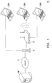
- FIG. 1 is a schematic diagram illustrating a remote control system according to an embodiment of the invention.
- a remote control system 10 includes a server 100 and electronic devices 200a, 200b, and 200c.
- the electronic devices 200a, 200b, and 200c have a network connection function and are remotely controllable.
- the electronic devices 200a, 200b, and 200c may be a desktop computer, a laptop computer, a tablet computer that can be linked to a network, or a corresponding mobile electronic device owned by the user.
- the electronic devices 200a, 200b, and 200c may connect to a network 11 to communicate with the server 100 through the network 11 in a normal operation mode.
- the server 100 may send a wake-up command through the network 11 to the electronic devices 200a, 200b, and 200c which are in a power-saving state according to the user's operation, so as to complete a network wake-up function.
- the electronic devices 200a, 200b, and 200c may return to an operation state from a sleep state or change from a shutdown state to a power-on state in response to the wake-up command sent by the server 100, such that the user may control the electronic devices 200a, 200b, and 200c remotely.
- the server 100 may be a cloud server connected to the network 11 or a server group formed by a plurality of physical equipment through cloud hardware sharing technology. A variety of hardware equipment of the server 100 is available. Thus, the invention is not intended to limit the type of the hardware equipment.
- the remotely-controllable electronic device may be connected to the network 11 by different connection methods.
- the electronic devices 200a, 200b, and 200c are basically connected to the network 11 through a modem 12.
- the modem 12 may be an Asymmetric Digital Subscriber Line modem (ADSL modem) or a cable modem, for example.
- ADSL modem Asymmetric Digital Subscriber Line modem
- cable modem a cable modem
- the invention is not intended to limit the type of the modem 12.
- the electronic device 200c may directly connect to the modem 12 in a wired or wireless manner to connect to the network 11.
- an Internet protocol router 13 is connected with the modem 12, and the electronic devices 200a and 200b may be connected to the Internet protocol router 13 in a wired or wireless manner to be connected to the network 11.
- the Internet protocol router 13 may be a network device, such as a wireless access point (AP) or an indoor router, for example.
- AP wireless access point
- FIG. 1 merely illustrates an example of the network connection of the remote control system 10, and thus should not be construed as a limitation to the invention.
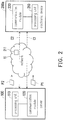
- FIG. 2 is a functional diagram illustrating an electronic device and a server according to an embodiment of the invention.
- the following descriptions are provided based on the electronic device 200a of FIG. 1 as an example. It should be noted that the invention is not limited thereto.
- the electronic devices 200b and 200c have hardware apparatuses and remote control function the same as or similar to those of the electronic device 200a.
- the server 100 includes a processing unit 110 and a communication module 120.
- the electronic device 200a includes a processing unit 210 and a communication module 220.
- the processing unit 110 of the server 100 is coupled to the communication module 120 of the server 100, and the processing unit 210 of the electronic device 200a is coupled to the communication module 220 of the electronic device 200a.
- the processing units 110 and 210 may be a central processing unit (CPU), a programmable microprocessor, a digital signal processor (DSP), a programmable controller, an application specific integrated circuit (ASIC), a programmable logic device (PLD), or other hardware devices with computing capability, for example.
- CPU central processing unit
- DSP digital signal processor
- ASIC application specific integrated circuit
- PLD programmable logic device
- the communication module 120 and the communication module 220 provide a function of network connection, which connects the electronic device 200a and the server 100 to the network 11.
- the communication module 120 and the communication module 220 may be implemented by software, hardware, or a combination of the foregoing. However, the invention is not limited thereto.
- the software may be a source code, application software, driver program, or a software module or function specialized for achieving a specific function, for example.
- the hardware may be a programmable controller, a digital signal processor (DSP), or other programmable microprocessors for general use or specific use, for example.
- the invention is not limited thereto.
- the communication module 220 of the electronic device 200a may be a physical Ethernet card and/or a wireless network card and a network chip used therein.
- the communication module 220 is configured to establish a network model low layer connection with the server 100 through the network 11, wherein the network model low layer connection may include physical layer connection and data link layer connection. More specifically, the network model low layer connection between the electronic device 200a and the server 100 is established by the communication module 220.
- the network model high layer connection between the electronic device 200a and the server 100 e.g. network layer connection, transport layer connection, session layer connection, presentation layer connection, and application layer connection, is established by the processing unit 210.
- the electronic device 200a can communicate with the server 100 through the network 11.
- the electronic device 200a may enter the power-saving state and stop supplying power to the processing unit 210, so as to reduce power consumption of the electronic device 200a.
- the communication module 120 remains operating normally to maintain the network model low layer connection with the server 100.
- the server 100 can wake up the electronic device 200a in the power-saving state through the network model low layer connection between the electronic device 200a and the server 100 to achieve the network wake-up function.
- the power-saving state of the electronic device may be a standby state, a sleep state, a connection standby state, or a shutdown state.
- the power-saving state is a S3 state (sleep state) defined according to the Advanced Configuration and Power Interface (ACPI) standard.
- the connection between the server 100 and the electronic device 200a in the power-saving state may be interrupted.
- the communication module 220 of the electronic device 200a may obtain a dynamic IP address through the ADSL modem 12 and Point-to-Point Protocol over Ethernet (PPPoE) connection to be connected to the network 11, so as to maintain the network model low layer connection with the server 100 through the network 11.
- PPPoE Point-to-Point Protocol over Ethernet
- the Internet protocol router 13 or the modem 12 may obtain the dynamic IP address associated with the electronic device 200a through the PPPoE connection. Nevertheless, the invention is not limited thereto.
- the communication module 220 of the electronic device 200a may obtain the dynamic IP address through the cable modem 12 and Dynamic Host Configuration Protocol (DHCP) connection to be connected to the network 11, so as to maintain the network model low layer connection with the server 100 through the network 11.
- DHCP Dynamic Host Configuration Protocol
- an Internet service provider (ISP) 211 that assigns the dynamic address changes the dynamic IP configuration due to a routing policy or other factors, the electronic device 200a would be disconnected from the network 11. In that case, the Internet protocol router 13 or the modem 12 may try to reconnect to the network 11 and obtain a new dynamic IP through the PPPoE connection, for example. Since the electronic device 200a is in the power-saving state, the electronic device 200a cannot detect that the dynamic IP has been reconfigured, and thus the server 100 cannot maintain the connection with the electronic device 200a with the previous dynamic IP.
- ISP Internet service provider
- the server 100 continuously sends a keep-alive packet P1 to the communication module 220 of the electronic device 200a through a first network connection C1 that has been established, and the communication module 220 also continuously detects the keep-alive packet P1. If the communication module 220 determines that an error or problem in receiving the keep-alive packet P1 occurs, the communication module 220 sends a wake-up signal to the processing unit 210, such that the electronic device 200a returns to the operation state from the power-saving state to establish a second network connection C2 with the server 100.
- the processing unit 210 may control the electronic device 200a to enter the power-saving state again and continuously detect a keep-alive packet P2 sent by the server 100 through the second network connection C2.
- FIG. 2 illustrates the example of using the electronic device 200a, the electronic devices 200b and 200c may maintain connection with the server 100 by the same method. Thus, details thereof are not repeated hereinafter.
- the electronic device 200a can instantly change from the power-saving state to the operation state to re-establish the connection, so as to maintain the connection between the server 100 and the electronic device 200a in the power-saving state.
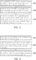
- FIG. 3 is a flowchart illustrating a method for keeping remote connection of the electronic device according to an embodiment of the invention. With reference to FIG. 3 , the method of this embodiment is applicable to the electronic device 200a of FIG. 2 . Below, steps of the method for keeping remote connection of the invention are explained in detail with reference to components of the electronic device 200a.
- the electronic device 200a when the electronic device 200a is to enter the power-saving state, the electronic device 200a is already connected to the network 11 and obtains a first Internet protocol address that is a dynamic address assigned by an ISP.
- the electronic device 200a sets network configuration of the first network connection C1 with the server 100 according to the first Internet protocol address to establish the first network connection C1 between the electronic device 200a and the server 100.
- Step S510 after the communication module 210 establishes the first network connection C1 between the electronic device 200a and the server 100, the processing unit 220 controls the electronic device 200a to enter the power-saving state from the operation state. It is known that the first network connection C1 is established based on the first Internet protocol address.
- Step S520 during a period that the electronic device 200a operates in the power-saving state, the communication module 210 continuously detects the keep-alive packet P1 sent by the server 100 through the first network connection C1. More specifically, the communication is still able to continuously receive the keep-aliv packet and detect whether an error of reception of the keep-alive packet occurs even when the electronic device 200a enters the power-saving state.
- Step S530 if an error of reception of the keep-alive packet P1 occurs, the processing unit 210 controls the electronic device 200a to return to the operation state from the power-saving state in response to the wake-up signal sent by the communication module 220, so as to establish the second network connection C2 between the electronic device 200a and the server 100.
- the error of reception of the keep-alive packet P1 includes a condition of not receiving the keep-alive packet P1 within a predetermined time.
- the keep-alive packet P1 conforms to a predefined packet pattern set by the electronic device 200a.
- a criterion e.g. predetermined waiting time
- the communication module 220 determines whether an error of reception of the keep-alive packet P1 occurs may be determined based on a frequency and a time interval at which the server 100 sends the keep-alive packet P1.
- the keep-alive packet may be implemented by a magic packet that is recognized by a network wake-up protocol and has a fixed specification.
- the aforementioned keep-alive packet may be implemented by other packet patterns that have another specification or self-defined packet patterns.
- the electronic device 200a may define the predetermined packet pattern (e.g. packet style, packet content, or packet encryption form) of the keep-alive packet by itself and notify the server 100 of the predetermined packet pattern corresponding to the keep-alive packet. Accordingly, the electronic device 200a and the server 100 achieve the method for keeping remote connection of the invention by using the specific predetermined packet pattern.
- the communication module 220 sends the wake-up signal to the processing unit 210, so as to cause the processing unit 210 to wake up and change to the operation state to establish the second network connection C2. Accordingly, the connection between the server 100 and the electronic device 200a is kept alive.
- the keep-alive packet P1 may not be successfully transmitted to the electronic device 200a because the Internet service provider 211 assigns a new second Internet protocol address to the electronic device 200a. That is to say, the server 100 is unaware of the change of the dynamic IP corresponding to the electronic device 200a and is unable to transmit the keep-alive packet P1 to the electronic device 200a through the first network connection C1 based on the first Internet protocol address. As a result, the communication module 220 cannot continuously receive the keep-alive packet P1.
- the communication module 220 determines that an error of reception of the keep-alive packet P1 occurs and sends the wake-up signal to the processing unit 210 to cause the processing unit 210 to change to the operation state and use the new second Internet protocol address to perform setting of the second network connection C2 with the server 100.
- FIG. 4 is a flowchart illustrating a method for keeping remote connection of the server according to an embodiment of the invention.
- the method of this embodiment is applicable to the server 100 of FIG. 2 .
- steps of the method for keeping remote connection of the invention are explained in detail with reference to components of the server 100.
- Step S610 the processing unit 110 of the server 100 controls the communication module 120 to establish the first network connection C1 between the server 100 and the electronic device 200a.
- the server 100 may receive a connection establishment request of the electronic device 200a and respond to the electronic device 200a with a connection establishment response, so as to perform setting of the first network connection C1 with the electronic device 200a.
- Step S620 after the electronic device 200a enters the power-saving state, the processing unit 110 controls the communication module 120 to continuously send the keep-alive packet P1 to the electronic device 200a through the first network connection C1.
- the processing unit 110 of the server 100 continuously sends the keep-alive packet P1 to the communication module 220 of the electronic device 200a based on the first Internet protocol address corresponding to the electronic device 200a.
- the invention is not intended to limit whether the keep-alive packet PI is sent regularly or irregularly.
- the server 100 sends one keep-alive packet P1 to the electronic device 200a at a fixed time interval (e.g. 30 seconds). That is, the frequency and time interval at which the server 100 sends the keep-alive packet may be designed according to the actual conditions. The invention is not intended to limit the frequency or the time interval. Moreover, the content of the keep-alive packet P1 may be encrypted or specially processed to increase security of the invention.
- Step S630 if the keep-alive packet P1 is not correctly transmitted to the electronic device 200a, the processing unit 110 uses the communication module 120 to receive the connection establishment request associated with the second network connection C2 from the electronic device 200a, so as to establish the second network connection C2 between the server 100 and the electronic device 200a.
- the second network connection C2 is established based on the second Internet protocol address. More specifically, the processing unit 110 updates the first Internet protocol address associated with the electronic device 200a to the second Internet protocol address, so as to continuously send the keep-alive packet P2 to the electronic device 200a that enters the power-saving state again through the second network connection C2 based on the second Internet protocol address.
- FIG. 5 is a flowchart illustrating a method for keeping remote connection of the electronic device according to an embodiment of the invention. With reference to FIG. 5 , the method of this embodiment is applicable to the electronic device 200a of FIG. 2 . Below, steps of the method for keeping remote connection of the invention are explained in detail with reference to components of the electronic device 200a.
- the processing unit 210 receives a power-saving state signal.
- the processing unit 210 may receive the power-saving state signal based on a sleep command given by the user and prepare to enter the power-saving state.
- the processing unit 210 may receive a power-saving state signal sent by an internal timing unit if not receiving any operation from the outside for a long period of time and accordingly prepare to enter the power-saving state.
- Step S720 the processing unit 210 controls the communication module 220 to perform setting of the first network connection C1 with the server 100.
- the processing unit determines the predefined packet pattern and notifies the server 100 of the predefined packet pattern of the electronic device 200a. Accordingly, the server 100 generates and transmits the keep-alive packet P1 according to the predefined packet pattern set by the electronic device 200a.
- the processing unit 210 controls the electronic device 200a to enter the power-saving state from the operation state.
- Step S750 the communication module 220 continuously detects the keep-alive packet P1 sent by the server 100 through the first network connection C1.
- Step S760 the communication module 220 determines whether the keep-alive packet P1 conforming to the predefined packet pattern set by the electronic device 200a is not received when the predetermined time expires. If the result of Step S760 is YES, Step S780 is performed such that the processing unit 210 returns to the operation state from the power-saving state in response to the wake-up signal. In other words, when the communication module 220 determines that an error of reception of the keep-alive packet P1 occurs, the communication module 220 sends the wake-up signal to wake up the processing unit 210 of the electronic device 200a. For example, it is given that the predetermined time for determining whether an error of reception of the keep-alive packet occurs is 120 seconds. If the communication module 220 does not receive any packet in 120 seconds after the counting starts, the communication module 220 determines that an error of reception of the keep-alive packet occurs and wakes up the processing unit 210.
- the predetermined time for determining whether an error of reception of the keep-alive packet occurs is 120 seconds.
- the communication module 220 receives a packet in 30 seconds after the counting starts, the received packet does not conform to the predefined packet pattern. Therefore, the communication module 220 continuously detects and determines whether the keep-alive packet that conforms to the predefined packet pattern set by the electronic device 200a is received in the remaining 90 seconds. If the communication module 220 receives the keep-alive packet P1 conforming to the form in the remaining 90 seconds, it means that the first network connection C1 between the electronic device 200a and the server 10 still exists. On the contrary, if the communication module 220 does not receive the keep-alive packet P1 conforming to the form in the remaining 90 seconds, the communication module 220 determines that an error of reception of the keep-alive packet occurs and wakes up the processing unit 210.
- Step S760 if the result of Step S760 is NO, the procedure returns to Step S750.
- the communication module 220 continuously receives the correct keep-alive packet in the predetermined waiting time, the electronic device 200a is maintained in the power-saving state and continues to detect the keep-alive packet sent by the server through the first network connection.
- Step S790 the woken processing unit 210 checks if the first network connection C1 still exists. If the first network connection C1 exists (the result of Step S790 is YES), the procedure returns to Step S730. On the contrary, if the first network connection C1 does not exist (the result of Step S790 is NO), the processing unit 210 controls the communication module 220 to establish the second network connection C2 between the electronic device 200a and the server 100.
- the communication module of the electronic device that is in the power-saving state instantly detects whether the network connection between the electronic device and the server still exists. If the network connection between the electronic device and the server no longer exists, the communication module of the electronic device sends the wake-up signal to the processing unit for the processing unit to control the electronic device to return to the operation state from the power-saving state and re-establish the connection with the server according to the current network connection environment and network connection parameters. Accordingly, the electronic device in the power-saving state is able to quickly detect whether there is an error in the connection with the server and instantly re-establish new connection, so as to keep the electronic device and the server connected at all times.
- the electronic device and the server can confirm and set the packet pattern of the keep-alive packet before entering the power-saving state, so as to detect whether the connection between the server and the electronic device exists by the keep-alive packet with device recognition or the encrypted keep-alive packet, thereby improving network security.
Landscapes
- Engineering & Computer Science (AREA)
- Computer Networks & Wireless Communication (AREA)
- Signal Processing (AREA)
- Small-Scale Networks (AREA)
- Data Exchanges In Wide-Area Networks (AREA)
Claims (8)
- Verfahren zum Aufrechterhalten einer Fernkopplung für ein elektronisches Gerät (200a, 200b, 200c), umfassend ein Kommunikationsmodul (220) und über das Kommunikationsmodul (220) eine Verbindung mit einem Netzwerk (11) herstellen, wobei das Verfahren zum Aufrechterhalten einer Fernkopplung umfasst:nachdem eine erste Netzwerkverbindung (C1) zwischen dem elektronischen Gerät (200a, 200b, 200c) und einem Server (100) hergestellt wurde, aus dem Betriebszustand (S510) in den Energiesparmodus übergehen, wobei das elektronische Gerät (200a, 200b, 200c) die Stromversorgung zur Verarbeitungseinheit (210) des elektronischen Geräts (200a, 200b, 200c) unterbricht, wenn das elektronische Gerät (200a, 200b, 200c) in den Energiesparmodus übergeht;während des Betriebs im Energiesparmodus ein vom Server (100) über die erste Netzwerkverbindung (C1) gesendetes Aufrechterhaltungspaket (Keep-Alive-Paket) (P1) kontinuierlich durch das Kommunikationsmodul (220) erfassen (S520, S750); undals Reaktion auf ein Wecksignal (Wake-Up-Signal) vom Energiesparmodus in den Betriebszustand zurückkehren (S530), um eine zweite Netzwerkverbindung (C2) zwischen dem elektronischen Gerät (200a, 200b, 200c) und dem Server (100) herzustellen, falls beim Aufrechterhaltungspaket (P1) ein Empfangsfehler aufgetreten ist,wobei der Fehler eine Bedingung umfasst, wonach kein Aufrechterhaltungspaket (P1) empfangen wird, das einem vom elektronisches Gerät (200a, 200b, 200c) innerhalb einer vorbestimmten Zeit festgelegten vordefinierten Paketmuster entspricht undwobei Schritt (S530), wonach als Reaktion auf ein Wecksignal (Wake-Up-Signal) vom Energiesparmodus in den Betriebszustand zurückgekehrt wird, um eine zweite Netzwerkverbindung (C2) zwischen dem elektronischen Gerät (200a, 200b, 200c) und einem Server (100) herzustellen, falls beim Aufrechterhaltungspaket (P1) ein Empfangsfehler aufgetreten ist, umfasst:prüfen (S790), ob die erste Netzwerkverbindung (C1) besteht, nachdem als Reaktion auf ein Wecksignal aus dem Energiesparmodus in den Betriebszustand zurückgekehrt wurde; undeine zweite Netzwerkverbindung (C2) zwischen dem elektronischen Gerät (200a, 200b, 200c) und einem Server (100) herstellen (S791), falls die erste Netzwerkverbindung (C1) nicht besteht.
- Verfahren zum Aufrechterhalten einer Fernkopplung gemäß Anspruch 1, wobei die erste Netzwerkverbindung (C1) basierend auf einer ersten Internetprotokolladresse hergestellt wird und die zweite Netzwerkverbindung (C2) basierend auf einer zweiten Internetprotokolladresse hergestellt wird, wobei die erste Internetprotokolladresse und die zweite Internetprotokolladresse dynamische Adressen sind.
wobei ein Internetdienstanbieter (ISP) (211) die erste Internetprotokolladresse und die zweite Internetprotokolladresse zuweist und das Verfahren zum Aufrechterhalten einer Fernkopplung ferner umfasst:eine Verbindung mit dem Netzwerk (11) herstellen und die erste Internetprotokolladresse erhalten; undeine erneute Verbindung mit dem Netzwerk (11) herstellen und die zweite Internetprotokolladresse erhalten, wenn die über die erste Internetprotokolladresse hergestellte Internetverbindung mit dem Netzwerk (11) unterbrochen wird. - Verfahren zum Aufrechterhalten einer Fernkopplung gemäß Anspruch 1, wobei Schritt (S510), wonach aus dem Betriebszustand in den Energiesparmodus übergegangen wird, nachdem eine erste Netzwerkverbindung (C1) zwischen dem elektronischen Gerät (200a, 200b, 200c) und einem Server (100) hergestellt wurde, umfasst:die Netzwerkkonfiguration der ersten Netzwerkverbindung (C1) mit dem Server (100) einrichten (S720), wenn Energiesparmodus-Signal empfangen (S710) wird;das vordefinierte Paketmuster bestimmen (S730) und den Server (100) über das dem elektronischen Gerät (200a, 200b, 200c) zugeordnete vordefinierte Paketmuster benachrichtigen, wobei der Server (100) das Aufrechterhaltungspaket (P1) gemäß dem vordefinierten Paketmuster sendet; undaus dem Betriebszustand in den Energiesparmodus übergehen (S740).
- Verfahren zum Aufrechterhalten einer Fernkopplung gemäß Anspruch 1, ferner umfassend, nachdem das Aufrechterhaltungspaket (P1) kontinuierlich über die erste Netzwerkverbindung (C1) an das elektronische Gerät (200a, 200b, 200c) gesendet wurde:vom Server (100) eine der zweiten Netzwerkverbindung (C2) des elektronischen Geräts (200a, 200b, 200c) zugeordnete Verbindungsaufbauanforderung empfangen, um die zweite Netzwerkverbindung (C2) zwischen dem Server (100) und dem elektronischen Gerät (200a, 200b, 200c) herzustellen, wenn im Aufrechterhaltungspaket (P1) ein Empfangsfehler aufgetreten ist,wobei die erste Netzwerkverbindung (C1) basierend auf einer ersten Internetprotokolladresse hergestellt wird und die zweite Netzwerkverbindung (C2) basierend auf einer zweiten Internetprotokolladresse hergestellt wird, wobei die erste Internetprotokolladresse und die zweite Internetprotokolladresse vom Internetdienstanbieter (211) zugeordnete dynamische Adressen sind.
- Verfahren zum Aufrechterhalten einer Fernkopplung gemäß Anspruch 4, ferner umfassend nachdem eine zweite Netzwerkverbindung (C2) zwischen dem elektronischen Gerät (200a, 200b, 200c) und einem Server (100) hergestellt wurde:
die erste dem elektronischen Gerät (200a, 200b, 200c) zugeordnete Internetprotokolladresse durch die zweite Internetprotokolladresse ersetzen, um das Aufrechterhaltungspaket (P1) durch den Server (100) anhand der zweiten Internetprotokolladresse kontinuierlich über die zweite Netzwerkverbindung (C2) an das elektronische Gerät (200a, 200b, 200c) zu senden. - Elektronisches Gerät (200a, 200b, 200c), umfassend:ein Kommunikationsmodul (220), dafür ausgelegt, eine Verbindung mit einem Netzwerk (11) herzustellen; undeine mit dem Kommunikationsmodul (220) gekoppelte Verarbeitungseinheit (210),wobei das Kommunikationsmodul (220) eine erste Netzwerkverbindung (C1) zwischen dem elektronischen Gerät (200a, 200b, 200c) und einem Server (100) herstellt und die Verarbeitungseinheit (210) das elektronische Gerät (200a, 200b, 200c) so steuert, dass es aus dem Betriebszustand in den Energiesparmodus übergeht, wobei das elektronische Gerät (200a, 200b, 200c) die Stromversorgung zur Verarbeitungseinheit (210) unterbricht, wenn das elektronische Gerät (200a, 200b, 200c) in den Energiesparmodus übergeht;wobei das Kommunikationsmodul (220) das vom Server (100) über die erste Netzwerkverbindung (C1) gesendete Aufrechterhaltungspaket (P1) kontinuierlich erfasst, während sich das elektronische Gerät (200a, 200b, 200c) im Energiesparmodus befindet,wobei die Verarbeitungseinheit (210) das elektronische Gerät (200a, 200b, 200c) so steuert, dass es als Reaktion auf ein vom Kommunikationsmodul (220) gesendetes Wecksignal aus dem Energiesparmodus in den Betriebszustand zurückkehrt, wenn beim Aufrechterhaltungspaket (P1) ein Empfangsfehler aufgetreten ist und die Verarbeitungseinheit (210) steuert das Kommunikationsmodul (220) so, dass dieses eine zweite Netzwerkverbindung (C2) zwischen dem elektronischen Gerät (200a, 200b, 200c) und dem Server (100) herstellt,wobei der Fehler eine Bedingung umfasst, wonach kein Aufrechterhaltungspaket (P1) empfangen wird, das bei Ablauf einer vorbestimmten Zeit einem vom elektronisches Gerät (200a, 200b, 200c) festgelegten vordefinierten Paketmuster entspricht,wobei die Verarbeitungseinheit (210) prüft, ob die erste Netzwerkverbindung (C1) besteht, nachdem das elektronische Gerät (200a, 200b, 200c) als Reaktion auf das Wecksignal aus dem Energiesparmodus in den Betriebszustand zurückgekehrt ist undwobei die Verarbeitungseinheit (210) das Kommunikationsmodul (220) so steuert, dass dieses eine zweite Netzwerkverbindung (C2) zwischen dem elektronischen Gerät (200a, 200b, 200c) und einem Server (100) herstellt, falls die erste Netzwerkverbindung (C1) nicht besteht.
- Elektronisches Gerät (200a, 200b, 200c) gemäß Anspruch 6, wobei die erste Netzwerkverbindung (C1) basierend auf einer ersten Internetprotokolladresse hergestellt wird und die zweite Netzwerkverbindung (C2) basierend auf einer zweiten Internetprotokolladresse hergestellt wird, wobei die erste Internetprotokolladresse und die zweite Internetprotokolladresse dynamische Adressen sind,
wobei ein Internetdienstanbieter (ISP) (211) die erste Internetprotokolladresse und die zweite Internetprotokolladresse zuweist und das Kommunikationsmodul (220) eine Verbindung mit dem Netzwerk (11) herstellt und die erste Internetprotokolladresse erhält,
wobei das Kommunikationsmodul (220) eine erneute Verbindung mit dem Netzwerk (11) herstellt und die zweite Internetprotokolladresse erhält, wenn die über die erste Internetprotokolladresse hergestellte Internetverbindung mit dem Netzwerk (11) unterbrochen wird. - Elektronisches Gerät (200a, 200b, 200c) gemäß Anspruch 6, wobei die Verarbeitungseinheit (210) das Kommunikationsmodul (220) so steuert, dass dieses eine Netzwerkkonfiguration für die erste Netzwerkverbindung (C1) mit dem Server (100) einrichtet, wenn die Verarbeitungseinheit (210) ein Energiesparmodus-Signal empfängt,
wobei die Verarbeitungseinheit (210) das vordefinierte Paketmuster bestimmt und den Server (100) über das dem elektronischen Gerät (200a, 200b, 200c) zugeordnete vordefinierte Paketmuster benachrichtigt, wobei der Server (100) das Aufrechterhaltungspaket (P1) gemäß dem vordefinierten Paketmuster sendet.
Applications Claiming Priority (1)
| Application Number | Priority Date | Filing Date | Title |
|---|---|---|---|
| TW103137838A TWI577154B (zh) | 2014-10-31 | 2014-10-31 | 保持遠端連線方法、電子裝置與伺服器 |
Publications (2)
| Publication Number | Publication Date |
|---|---|
| EP3016448A1 EP3016448A1 (de) | 2016-05-04 |
| EP3016448B1 true EP3016448B1 (de) | 2019-08-07 |
Family
ID=53483655
Family Applications (1)
| Application Number | Title | Priority Date | Filing Date |
|---|---|---|---|
| EP15169728.1A Active EP3016448B1 (de) | 2014-10-31 | 2015-05-28 | Verfahren zur aufrechterhaltung einer fernverbindung und elektronische vorrichtung |
Country Status (3)
| Country | Link |
|---|---|
| US (1) | US9819640B2 (de) |
| EP (1) | EP3016448B1 (de) |
| TW (1) | TWI577154B (de) |
Families Citing this family (9)
| Publication number | Priority date | Publication date | Assignee | Title |
|---|---|---|---|---|
| KR102099204B1 (ko) * | 2013-09-02 | 2020-05-15 | 삼성전자주식회사 | 전자장치 및 전자장치의 통신연결방법 |
| US10505869B2 (en) * | 2015-08-04 | 2019-12-10 | International Business Machines Corporation | Mimicking a presence notification from an application executing on a virtual component to optimize computing resource allocation/utilization |
| CN107968713B (zh) * | 2016-10-20 | 2021-11-19 | 北京华为数字技术有限公司 | 远程唤醒方法、装置及系统 |
| JP6822180B2 (ja) * | 2017-02-02 | 2021-01-27 | セイコーエプソン株式会社 | 印刷装置、印刷装置の制御方法、及び、通信システム |
| JP7339037B2 (ja) * | 2019-07-10 | 2023-09-05 | ファナック株式会社 | 制御装置、診断方法及び診断プログラム |
| CN115701070B (zh) * | 2021-07-16 | 2025-09-12 | 京东方科技集团股份有限公司 | 计算机设备及其远程控制方法、相关设备 |
| US11500449B1 (en) * | 2021-07-20 | 2022-11-15 | Dell Products L.P. | Adaptive remediation for modern standby |
| CN114155636B (zh) * | 2021-12-14 | 2024-06-04 | 深圳Tcl新技术有限公司 | 设备控制方法、装置、电子设备及存储介质 |
| CN117641151A (zh) * | 2022-08-10 | 2024-03-01 | 中国石油天然气集团有限公司 | 一种电磁采集仪器及数据采集方法 |
Citations (1)
| Publication number | Priority date | Publication date | Assignee | Title |
|---|---|---|---|---|
| US20130067060A1 (en) * | 2011-09-09 | 2013-03-14 | David G. Thaler | Wake Pattern Management |
Family Cites Families (36)
| Publication number | Priority date | Publication date | Assignee | Title |
|---|---|---|---|---|
| US6212175B1 (en) * | 1997-04-22 | 2001-04-03 | Telxon Corporation | Method to sustain TCP connection |
| US7647422B2 (en) * | 2001-11-06 | 2010-01-12 | Enterasys Networks, Inc. | VPN failure recovery |
| US7623497B2 (en) * | 2002-04-15 | 2009-11-24 | Qualcomm, Incorporated | Methods and apparatus for extending mobile IP |
| US8707406B2 (en) * | 2002-07-26 | 2014-04-22 | Sierra Wireless, Inc. | Always-on virtual private network access |
| US7788674B1 (en) * | 2004-02-19 | 2010-08-31 | Michael Siegenfeld | Computer software framework for developing secure, scalable, and distributed applications and methods and applications thereof |
| US7555570B2 (en) * | 2006-02-17 | 2009-06-30 | Avocent Huntsville Corporation | Device and method for configuring a target device |
| US7882255B2 (en) * | 2006-03-29 | 2011-02-01 | Intel Corporation | Method and apparatus for maintaining local area network (“LAN”) and wireless LAN (“WLAN”) security associations |
| US20080101445A1 (en) * | 2006-08-31 | 2008-05-01 | Stoke,Inc. | DSL wake-up |
| US7698409B2 (en) * | 2006-12-22 | 2010-04-13 | Nokia Corporation | Method and an apparatus for executing timed network operations |
| US20090094349A1 (en) * | 2007-03-14 | 2009-04-09 | Amx, Llc | Device roaming on a zigbee network |
| US8773086B1 (en) * | 2007-12-07 | 2014-07-08 | Marvell International Ltd. | Circuits and methods for dynamic voltage management |
| US20090271517A1 (en) * | 2008-04-25 | 2009-10-29 | Webmessenger, Inc. | Method and apparatus for wireless device reconnection handling |
| US9516116B2 (en) * | 2008-06-06 | 2016-12-06 | Apple Inc. | Managing notification service connections |
| US8135392B2 (en) * | 2008-06-06 | 2012-03-13 | Apple Inc. | Managing notification service connections and displaying icon badges |
| US20100039971A1 (en) * | 2008-08-15 | 2010-02-18 | Hong Kong Applied Science and Technology Research Institute, Co. | Power Management Method and Communication System |
| US8811248B2 (en) * | 2008-10-03 | 2014-08-19 | Mimos Berhad | Method for extending battery life in a wireless device |
| KR101512493B1 (ko) * | 2009-02-06 | 2015-04-15 | 삼성전자주식회사 | 저전력 시스템온칩 |
| US9065685B2 (en) * | 2009-02-13 | 2015-06-23 | Cisco Technology, Inc. | Network switch employing a proxy to facilitate power savings in a telephone network |
| EP2446673B1 (de) * | 2009-06-24 | 2016-03-23 | Telefonaktiebolaget LM Ericsson (publ) | Energieeffiziente baisistation mit eintritt in den ruhemodus |
| US9098279B2 (en) * | 2010-09-14 | 2015-08-04 | Google Inc. | Methods and systems for data interchange between a network-connected thermostat and cloud-based management server |
| US8661290B2 (en) * | 2011-01-14 | 2014-02-25 | International Business Machines Corporation | Saving power in computing systems with redundant service processors |
| CN103430605A (zh) * | 2011-03-07 | 2013-12-04 | 英特尔公司 | 编组机器对机器通信 |
| CN103503422A (zh) * | 2011-04-29 | 2014-01-08 | 瑞典爱立信有限公司 | 自动连接选择 |
| US8566625B2 (en) * | 2011-07-01 | 2013-10-22 | Intel Corporation | System and method for determining transmitting frequency to maintain remote application server connectivity |
| US9125152B2 (en) * | 2011-08-16 | 2015-09-01 | Utc Fire & Security Corporation | Beacon synchronization in wifi based systems |
| CN102395119B (zh) * | 2011-11-15 | 2014-11-19 | 华为技术有限公司 | 一种支持应用客户端永久在线的方法、系统及装置 |
| US8868065B2 (en) * | 2012-06-08 | 2014-10-21 | Apple Inc. | System and method for reducing power consumption for push messaging |
| JP2014005323A (ja) * | 2012-06-21 | 2014-01-16 | Nitto Denko Corp | シリコーン樹脂組成物 |
| CN103517266B (zh) * | 2012-06-29 | 2017-03-22 | 国际商业机器公司 | 移动网络侧激活移动终端的方法和移动网关系统 |
| US20140098727A1 (en) * | 2012-10-04 | 2014-04-10 | Apple Inc. | Methods and apparatus for network signaling during low-power operation |
| WO2014066393A1 (en) * | 2012-10-22 | 2014-05-01 | Interdigital Patent Holdings, Inc. | Method and apparatus for negotiating "keep-alive" message frequencies of applications running on a mobile station |
| TW201426667A (zh) * | 2012-12-21 | 2014-07-01 | Taiwan Secom Co Ltd | 具省電功能之感知裝置之保全系統 |
| US9350550B2 (en) * | 2013-09-10 | 2016-05-24 | M2M And Iot Technologies, Llc | Power management and security for wireless modules in “machine-to-machine” communications |
| TWI498739B (zh) * | 2013-12-17 | 2015-09-01 | Inwellcom Technology Corp | Remote control system and control method |
| US9838245B2 (en) * | 2014-01-15 | 2017-12-05 | Dell Products, L.P. | Systems and methods for improved fault tolerance in solicited information handling systems |
| US10251130B2 (en) * | 2014-06-30 | 2019-04-02 | Lenovo (Singapore) Pte. Ltd. | Adaptive and static keep alive message detection and simulation |
-
2014
- 2014-10-31 TW TW103137838A patent/TWI577154B/zh active
-
2015
- 2015-05-13 US US14/710,598 patent/US9819640B2/en active Active
- 2015-05-28 EP EP15169728.1A patent/EP3016448B1/de active Active
Patent Citations (1)
| Publication number | Priority date | Publication date | Assignee | Title |
|---|---|---|---|---|
| US20130067060A1 (en) * | 2011-09-09 | 2013-03-14 | David G. Thaler | Wake Pattern Management |
Also Published As
| Publication number | Publication date |
|---|---|
| TW201616832A (zh) | 2016-05-01 |
| US20160127308A1 (en) | 2016-05-05 |
| EP3016448A1 (de) | 2016-05-04 |
| US9819640B2 (en) | 2017-11-14 |
| TWI577154B (zh) | 2017-04-01 |
Similar Documents
| Publication | Publication Date | Title |
|---|---|---|
| US9819640B2 (en) | Method for keeping remote connection, electronic device and server | |
| US9152195B2 (en) | Wake on cloud | |
| CN101489294B (zh) | 调整功率的方法、路由器和网络设备 | |
| EP2224311B1 (de) | System und Verfahren für Energieeinsparungen durch Nachahmung des Aufwachens in einem LAN in einem energieeffizienten Ethernet | |
| US9497030B2 (en) | Remotely controllable electronic device and system including the same | |
| US20110029659A1 (en) | Method and System for Network Proxy Services for Energy Efficient Networking | |
| EP2339792B1 (de) | Verfahren für den Zugriff auf eine USB-Vorrichtung, die mit einem Heimat-Gateway verbunden ist, Heimat-Gateway und Endgerät | |
| TWI766035B (zh) | 用於裝置管理之系統及方法 | |
| EP2856698B1 (de) | Netzwerk- anwesenheitsweitergabe | |
| US9519327B2 (en) | Communication apparatus and control method therefor | |
| WO2018157689A1 (zh) | 一种实现蓝牙安全设备低功耗待机的方法及蓝牙安全设备 | |
| CN105704157A (zh) | 远程控制方法及系统、所适用的智能终端和服务端 | |
| CN107508693A (zh) | 路由器控制方法、装置及电源适配器、路由器 | |
| WO2015154462A1 (zh) | 一种即时通讯应用程序管理方法、装置及其移动终端 | |
| US9201663B2 (en) | Computer system and remote control method for computer device | |
| US20100257384A1 (en) | Device and Method for Remote Wake-Up | |
| US10488909B2 (en) | Communicating commands to an embedded controller of a system | |
| US7882255B2 (en) | Method and apparatus for maintaining local area network (“LAN”) and wireless LAN (“WLAN”) security associations | |
| CN102413179A (zh) | 自动开机或唤醒机器及其开机或唤醒方法 | |
| CN215867831U (zh) | 一种休眠唤醒装置和nas存储系统 | |
| CN105656846A (zh) | 保持远端连接方法、电子装置与服务器 | |
| TWI469053B (zh) | 電子裝置及其啟動方法 | |
| TWI488530B (zh) | 處理網路連線的方法及其電子裝置 | |
| CN116156607A (zh) | 智能终端唤醒方法以及智能终端 | |
| JP2017069664A (ja) | 無線中継装置 |
Legal Events
| Date | Code | Title | Description |
|---|---|---|---|
| PUAI | Public reference made under article 153(3) epc to a published international application that has entered the european phase |
Free format text: ORIGINAL CODE: 0009012 |
|
| AK | Designated contracting states |
Kind code of ref document: A1 Designated state(s): AL AT BE BG CH CY CZ DE DK EE ES FI FR GB GR HR HU IE IS IT LI LT LU LV MC MK MT NL NO PL PT RO RS SE SI SK SM TR |
|
| AX | Request for extension of the european patent |
Extension state: BA ME |
|
| 17P | Request for examination filed |
Effective date: 20160803 |
|
| RBV | Designated contracting states (corrected) |
Designated state(s): AL AT BE BG CH CY CZ DE DK EE ES FI FR GB GR HR HU IE IS IT LI LT LU LV MC MK MT NL NO PL PT RO RS SE SI SK SM TR |
|
| STAA | Information on the status of an ep patent application or granted ep patent |
Free format text: STATUS: EXAMINATION IS IN PROGRESS |
|
| 17Q | First examination report despatched |
Effective date: 20170217 |
|
| GRAP | Despatch of communication of intention to grant a patent |
Free format text: ORIGINAL CODE: EPIDOSNIGR1 |
|
| STAA | Information on the status of an ep patent application or granted ep patent |
Free format text: STATUS: GRANT OF PATENT IS INTENDED |
|
| RIC1 | Information provided on ipc code assigned before grant |
Ipc: H04W 40/00 20090101ALN20190313BHEP Ipc: H04L 29/08 20060101ALI20190313BHEP Ipc: H04W 76/25 20180101ALN20190313BHEP Ipc: H04W 76/28 20180101ALN20190313BHEP Ipc: H04W 52/02 20090101AFI20190313BHEP Ipc: H04L 12/751 20130101ALN20190313BHEP Ipc: H04L 12/703 20130101ALI20190313BHEP Ipc: H04L 29/12 20060101ALI20190313BHEP |
|
| INTG | Intention to grant announced |
Effective date: 20190404 |
|
| GRAS | Grant fee paid |
Free format text: ORIGINAL CODE: EPIDOSNIGR3 |
|
| GRAA | (expected) grant |
Free format text: ORIGINAL CODE: 0009210 |
|
| STAA | Information on the status of an ep patent application or granted ep patent |
Free format text: STATUS: THE PATENT HAS BEEN GRANTED |
|
| AK | Designated contracting states |
Kind code of ref document: B1 Designated state(s): AL AT BE BG CH CY CZ DE DK EE ES FI FR GB GR HR HU IE IS IT LI LT LU LV MC MK MT NL NO PL PT RO RS SE SI SK SM TR |
|
| REG | Reference to a national code |
Ref country code: GB Ref legal event code: FG4D |
|
| REG | Reference to a national code |
Ref country code: CH Ref legal event code: EP Ref country code: AT Ref legal event code: REF Ref document number: 1165799 Country of ref document: AT Kind code of ref document: T Effective date: 20190815 |
|
| REG | Reference to a national code |
Ref country code: DE Ref legal event code: R096 Ref document number: 602015035103 Country of ref document: DE |
|
| REG | Reference to a national code |
Ref country code: IE Ref legal event code: FG4D |
|
| REG | Reference to a national code |
Ref country code: NL Ref legal event code: MP Effective date: 20190807 |
|
| REG | Reference to a national code |
Ref country code: LT Ref legal event code: MG4D |
|
| PG25 | Lapsed in a contracting state [announced via postgrant information from national office to epo] |
Ref country code: LT Free format text: LAPSE BECAUSE OF FAILURE TO SUBMIT A TRANSLATION OF THE DESCRIPTION OR TO PAY THE FEE WITHIN THE PRESCRIBED TIME-LIMIT Effective date: 20190807 Ref country code: HR Free format text: LAPSE BECAUSE OF FAILURE TO SUBMIT A TRANSLATION OF THE DESCRIPTION OR TO PAY THE FEE WITHIN THE PRESCRIBED TIME-LIMIT Effective date: 20190807 Ref country code: NO Free format text: LAPSE BECAUSE OF FAILURE TO SUBMIT A TRANSLATION OF THE DESCRIPTION OR TO PAY THE FEE WITHIN THE PRESCRIBED TIME-LIMIT Effective date: 20191107 Ref country code: SE Free format text: LAPSE BECAUSE OF FAILURE TO SUBMIT A TRANSLATION OF THE DESCRIPTION OR TO PAY THE FEE WITHIN THE PRESCRIBED TIME-LIMIT Effective date: 20190807 Ref country code: FI Free format text: LAPSE BECAUSE OF FAILURE TO SUBMIT A TRANSLATION OF THE DESCRIPTION OR TO PAY THE FEE WITHIN THE PRESCRIBED TIME-LIMIT Effective date: 20190807 Ref country code: PT Free format text: LAPSE BECAUSE OF FAILURE TO SUBMIT A TRANSLATION OF THE DESCRIPTION OR TO PAY THE FEE WITHIN THE PRESCRIBED TIME-LIMIT Effective date: 20191209 Ref country code: BG Free format text: LAPSE BECAUSE OF FAILURE TO SUBMIT A TRANSLATION OF THE DESCRIPTION OR TO PAY THE FEE WITHIN THE PRESCRIBED TIME-LIMIT Effective date: 20191107 Ref country code: NL Free format text: LAPSE BECAUSE OF FAILURE TO SUBMIT A TRANSLATION OF THE DESCRIPTION OR TO PAY THE FEE WITHIN THE PRESCRIBED TIME-LIMIT Effective date: 20190807 |
|
| REG | Reference to a national code |
Ref country code: AT Ref legal event code: MK05 Ref document number: 1165799 Country of ref document: AT Kind code of ref document: T Effective date: 20190807 |
|
| PG25 | Lapsed in a contracting state [announced via postgrant information from national office to epo] |
Ref country code: IS Free format text: LAPSE BECAUSE OF FAILURE TO SUBMIT A TRANSLATION OF THE DESCRIPTION OR TO PAY THE FEE WITHIN THE PRESCRIBED TIME-LIMIT Effective date: 20191207 Ref country code: RS Free format text: LAPSE BECAUSE OF FAILURE TO SUBMIT A TRANSLATION OF THE DESCRIPTION OR TO PAY THE FEE WITHIN THE PRESCRIBED TIME-LIMIT Effective date: 20190807 Ref country code: GR Free format text: LAPSE BECAUSE OF FAILURE TO SUBMIT A TRANSLATION OF THE DESCRIPTION OR TO PAY THE FEE WITHIN THE PRESCRIBED TIME-LIMIT Effective date: 20191108 Ref country code: AL Free format text: LAPSE BECAUSE OF FAILURE TO SUBMIT A TRANSLATION OF THE DESCRIPTION OR TO PAY THE FEE WITHIN THE PRESCRIBED TIME-LIMIT Effective date: 20190807 Ref country code: LV Free format text: LAPSE BECAUSE OF FAILURE TO SUBMIT A TRANSLATION OF THE DESCRIPTION OR TO PAY THE FEE WITHIN THE PRESCRIBED TIME-LIMIT Effective date: 20190807 Ref country code: ES Free format text: LAPSE BECAUSE OF FAILURE TO SUBMIT A TRANSLATION OF THE DESCRIPTION OR TO PAY THE FEE WITHIN THE PRESCRIBED TIME-LIMIT Effective date: 20190807 |
|
| PG25 | Lapsed in a contracting state [announced via postgrant information from national office to epo] |
Ref country code: TR Free format text: LAPSE BECAUSE OF FAILURE TO SUBMIT A TRANSLATION OF THE DESCRIPTION OR TO PAY THE FEE WITHIN THE PRESCRIBED TIME-LIMIT Effective date: 20190807 |
|
| PG25 | Lapsed in a contracting state [announced via postgrant information from national office to epo] |
Ref country code: AT Free format text: LAPSE BECAUSE OF FAILURE TO SUBMIT A TRANSLATION OF THE DESCRIPTION OR TO PAY THE FEE WITHIN THE PRESCRIBED TIME-LIMIT Effective date: 20190807 Ref country code: DK Free format text: LAPSE BECAUSE OF FAILURE TO SUBMIT A TRANSLATION OF THE DESCRIPTION OR TO PAY THE FEE WITHIN THE PRESCRIBED TIME-LIMIT Effective date: 20190807 Ref country code: PL Free format text: LAPSE BECAUSE OF FAILURE TO SUBMIT A TRANSLATION OF THE DESCRIPTION OR TO PAY THE FEE WITHIN THE PRESCRIBED TIME-LIMIT Effective date: 20190807 Ref country code: RO Free format text: LAPSE BECAUSE OF FAILURE TO SUBMIT A TRANSLATION OF THE DESCRIPTION OR TO PAY THE FEE WITHIN THE PRESCRIBED TIME-LIMIT Effective date: 20190807 Ref country code: IT Free format text: LAPSE BECAUSE OF FAILURE TO SUBMIT A TRANSLATION OF THE DESCRIPTION OR TO PAY THE FEE WITHIN THE PRESCRIBED TIME-LIMIT Effective date: 20190807 Ref country code: EE Free format text: LAPSE BECAUSE OF FAILURE TO SUBMIT A TRANSLATION OF THE DESCRIPTION OR TO PAY THE FEE WITHIN THE PRESCRIBED TIME-LIMIT Effective date: 20190807 |
|
| PG25 | Lapsed in a contracting state [announced via postgrant information from national office to epo] |
Ref country code: IS Free format text: LAPSE BECAUSE OF FAILURE TO SUBMIT A TRANSLATION OF THE DESCRIPTION OR TO PAY THE FEE WITHIN THE PRESCRIBED TIME-LIMIT Effective date: 20200224 Ref country code: SM Free format text: LAPSE BECAUSE OF FAILURE TO SUBMIT A TRANSLATION OF THE DESCRIPTION OR TO PAY THE FEE WITHIN THE PRESCRIBED TIME-LIMIT Effective date: 20190807 Ref country code: CZ Free format text: LAPSE BECAUSE OF FAILURE TO SUBMIT A TRANSLATION OF THE DESCRIPTION OR TO PAY THE FEE WITHIN THE PRESCRIBED TIME-LIMIT Effective date: 20190807 Ref country code: SK Free format text: LAPSE BECAUSE OF FAILURE TO SUBMIT A TRANSLATION OF THE DESCRIPTION OR TO PAY THE FEE WITHIN THE PRESCRIBED TIME-LIMIT Effective date: 20190807 |
|
| REG | Reference to a national code |
Ref country code: DE Ref legal event code: R097 Ref document number: 602015035103 Country of ref document: DE |
|
| PLBE | No opposition filed within time limit |
Free format text: ORIGINAL CODE: 0009261 |
|
| STAA | Information on the status of an ep patent application or granted ep patent |
Free format text: STATUS: NO OPPOSITION FILED WITHIN TIME LIMIT |
|
| PG2D | Information on lapse in contracting state deleted |
Ref country code: IS |
|
| 26N | No opposition filed |
Effective date: 20200603 |
|
| PG25 | Lapsed in a contracting state [announced via postgrant information from national office to epo] |
Ref country code: SI Free format text: LAPSE BECAUSE OF FAILURE TO SUBMIT A TRANSLATION OF THE DESCRIPTION OR TO PAY THE FEE WITHIN THE PRESCRIBED TIME-LIMIT Effective date: 20190807 |
|
| PG25 | Lapsed in a contracting state [announced via postgrant information from national office to epo] |
Ref country code: CH Free format text: LAPSE BECAUSE OF NON-PAYMENT OF DUE FEES Effective date: 20200531 Ref country code: MC Free format text: LAPSE BECAUSE OF FAILURE TO SUBMIT A TRANSLATION OF THE DESCRIPTION OR TO PAY THE FEE WITHIN THE PRESCRIBED TIME-LIMIT Effective date: 20190807 Ref country code: LI Free format text: LAPSE BECAUSE OF NON-PAYMENT OF DUE FEES Effective date: 20200531 |
|
| REG | Reference to a national code |
Ref country code: BE Ref legal event code: MM Effective date: 20200531 |
|
| PG25 | Lapsed in a contracting state [announced via postgrant information from national office to epo] |
Ref country code: LU Free format text: LAPSE BECAUSE OF NON-PAYMENT OF DUE FEES Effective date: 20200528 |
|
| PG25 | Lapsed in a contracting state [announced via postgrant information from national office to epo] |
Ref country code: IE Free format text: LAPSE BECAUSE OF NON-PAYMENT OF DUE FEES Effective date: 20200528 |
|
| PG25 | Lapsed in a contracting state [announced via postgrant information from national office to epo] |
Ref country code: BE Free format text: LAPSE BECAUSE OF NON-PAYMENT OF DUE FEES Effective date: 20200531 |
|
| PG25 | Lapsed in a contracting state [announced via postgrant information from national office to epo] |
Ref country code: MT Free format text: LAPSE BECAUSE OF FAILURE TO SUBMIT A TRANSLATION OF THE DESCRIPTION OR TO PAY THE FEE WITHIN THE PRESCRIBED TIME-LIMIT Effective date: 20190807 Ref country code: CY Free format text: LAPSE BECAUSE OF FAILURE TO SUBMIT A TRANSLATION OF THE DESCRIPTION OR TO PAY THE FEE WITHIN THE PRESCRIBED TIME-LIMIT Effective date: 20190807 |
|
| PG25 | Lapsed in a contracting state [announced via postgrant information from national office to epo] |
Ref country code: MK Free format text: LAPSE BECAUSE OF FAILURE TO SUBMIT A TRANSLATION OF THE DESCRIPTION OR TO PAY THE FEE WITHIN THE PRESCRIBED TIME-LIMIT Effective date: 20190807 |
|
| REG | Reference to a national code |
Ref country code: FR Ref legal event code: PLFP Year of fee payment: 9 |
|
| PGFP | Annual fee paid to national office [announced via postgrant information from national office to epo] |
Ref country code: DE Payment date: 20250402 Year of fee payment: 11 |
|
| PGFP | Annual fee paid to national office [announced via postgrant information from national office to epo] |
Ref country code: GB Payment date: 20250401 Year of fee payment: 11 |
|
| PGFP | Annual fee paid to national office [announced via postgrant information from national office to epo] |
Ref country code: FR Payment date: 20250401 Year of fee payment: 11 |