EP3016331B1 - Route distributing method, system and apparatus - Google Patents
Route distributing method, system and apparatus Download PDFInfo
- Publication number
- EP3016331B1 EP3016331B1 EP13890351.3A EP13890351A EP3016331B1 EP 3016331 B1 EP3016331 B1 EP 3016331B1 EP 13890351 A EP13890351 A EP 13890351A EP 3016331 B1 EP3016331 B1 EP 3016331B1
- Authority
- EP
- European Patent Office
- Prior art keywords
- router
- physical
- controller
- logical
- route
- Prior art date
- Legal status (The legal status is an assumption and is not a legal conclusion. Google has not performed a legal analysis and makes no representation as to the accuracy of the status listed.)
- Active
Links
- 238000000034 method Methods 0.000 title claims description 32
- 238000013507 mapping Methods 0.000 claims description 13
- 238000010586 diagram Methods 0.000 description 13
- 230000005540 biological transmission Effects 0.000 description 5
- 238000004891 communication Methods 0.000 description 3
- 238000005516 engineering process Methods 0.000 description 2
- 230000003287 optical effect Effects 0.000 description 1
- 230000000750 progressive effect Effects 0.000 description 1
Images


Classifications
-
- H—ELECTRICITY
- H04—ELECTRIC COMMUNICATION TECHNIQUE
- H04L—TRANSMISSION OF DIGITAL INFORMATION, e.g. TELEGRAPHIC COMMUNICATION
- H04L45/00—Routing or path finding of packets in data switching networks
- H04L45/22—Alternate routing
-
- H—ELECTRICITY
- H04—ELECTRIC COMMUNICATION TECHNIQUE
- H04L—TRANSMISSION OF DIGITAL INFORMATION, e.g. TELEGRAPHIC COMMUNICATION
- H04L12/00—Data switching networks
- H04L12/64—Hybrid switching systems
- H04L12/6418—Hybrid transport
-
- H—ELECTRICITY
- H04—ELECTRIC COMMUNICATION TECHNIQUE
- H04L—TRANSMISSION OF DIGITAL INFORMATION, e.g. TELEGRAPHIC COMMUNICATION
- H04L45/00—Routing or path finding of packets in data switching networks
- H04L45/02—Topology update or discovery
-
- H—ELECTRICITY
- H04—ELECTRIC COMMUNICATION TECHNIQUE
- H04L—TRANSMISSION OF DIGITAL INFORMATION, e.g. TELEGRAPHIC COMMUNICATION
- H04L45/00—Routing or path finding of packets in data switching networks
- H04L45/02—Topology update or discovery
- H04L45/033—Topology update or discovery by updating distance vector protocols
-
- H—ELECTRICITY
- H04—ELECTRIC COMMUNICATION TECHNIQUE
- H04L—TRANSMISSION OF DIGITAL INFORMATION, e.g. TELEGRAPHIC COMMUNICATION
- H04L47/00—Traffic control in data switching networks
- H04L47/10—Flow control; Congestion control
- H04L47/12—Avoiding congestion; Recovering from congestion
- H04L47/122—Avoiding congestion; Recovering from congestion by diverting traffic away from congested entities
Definitions
- the present invention relates to the field of network communications technologies, and in particular, to a route advertisement method, a system, and a controller.
- An autonomous system generally includes multiple routers, and the routers communicate by using the Border Gateway Protocol (BGP).
- BGP Border Gateway Protocol
- AS is a dynamic routing protocol deployed within an AS and between ASs, and is primarily used to exchange routing information and construct a propagation path to prevent generation of a routing loop.
- a router within an AS is also referred to as a peer (Peer).
- Peer peer
- a router within an AS is configured as a Route Reflector (RR), and other routers except the RR are referred to as clients (Client).
- RR Route Reflector
- clients clients
- a connection is established between the RR and each client, but no connection needs to be established between clients.
- the RR reflects routing information between the clients.
- the prior art has the following disadvantages: because the RR selects only one egress router and sends the route of the egress router to all clients, when any client receives traffic that is transmitted to a router corresponding to the destination address, the client needs to calculate a next-hop route of the client and finally route the traffic to the one egress router, which tends to cause congestion of the egress router and degrades performance of a routing network.
- a method of information distribution in a wireless communication system comprises receiving an information advertisement signal by a propagator node, wherein said information advertisement signal identifies information available from a distributor node; storing said information advertisement signal by said propagator node in a distributor routing table; and forwarding said information advertisement signal by said propagator node to another propagator node, a selector node, or both.
- Embodiments of the present invention provide a route advertisement method, system and controller to resolve a problem in the prior art that advertised routes are likely to cause congestion at a route egress and thereby lead to low routing performance of a network.
- the method further includes:
- the method before the receiving, by the physical controller, routing information reported by at least one physical router of the multiple physical routers, the method further includes:
- the generating, by the physical controller, a route for a physical router in the traffic path includes:
- the generating, by the physical controller, a route for a physical router in the traffic path includes:
- a controller serves as a physical controller and is applied to a routing network which is based on Border Gateway Protocol BGP, where the routing network further includes multiple physical routers connected to the physical controller, and the controller includes:
- the controller further includes:
- the controller further includes:
- the generating unit is specifically configured to generate the route for the physical router in the traffic path by using the logical controller; and the advertising unit is specifically configured to: deliver, by using the logical controller, the route to a logical router corresponding to the physical router in the traffic path, where the route is generated for the physical router in the traffic path, and forward, by using the logical router, the generated route to the physical router corresponding to the logical router.
- the generating unit is specifically configured to deliver the routing information to the multiple logical routers by using the logical controller, so that a logical router corresponding to the physical router in the traffic path generates the route for the physical router in the traffic path; and the advertising unit is specifically configured to deliver the generated route to the physical router in the traffic path by using the logical router corresponding to the physical router in the traffic path.
- a route advertisement system is provided, where the system is applied to a routing network which is based on Border Gateway Protocol BGP, and the system includes a physical controller according to the second aspect or any possible implementation manner of the second aspect and multiple physical routers connected to the physical controller, where the physical router is configured to receive routing information reported by a destination router connected to the physical router, where the routing information includes a destination address of the destination router.
- the generating unit is specifically configured to generate the route for the physical router in the traffic path by using the logical controller; and the advertising unit is specifically configured to: deliver, by using the logical controller, the route to a logical router corresponding to the physical router in the traffic path, where the route is generated for the physical router in the traffic path, and forward, by using the logical router, the generated route to the physical router corresponding to the logical router.
- the generating unit is specifically configured to deliver the routing information to the multiple logical routers by using the logical controller, so that a logical router corresponding to the physical router in the traffic path generates the route for the physical router in the traffic path; and the advertising unit is specifically configured to deliver the generated route to the physical router in the traffic path by using the logical router corresponding to the physical router in the traffic path.
- a controller serves as a physical controller and is applied to a routing network which is based on Border Gateway Protocol BGP, where the routing network further includes multiple physical routers connected to the physical controller, and the controller includes a network interface and a processor, where the network interface is configured to receive routing information reported by at least one physical router of the multiple physical routers, where the routing information includes a destination address of a destination router connected to the at least one physical router; and the processor is configured to obtain a traffic path in which the at least one physical router is used as an egress router to transmit traffic to the destination router, generate a route for a physical router in the traffic path, and deliver the generated route to a corresponding physical router through the network interface.
- Border Gateway Protocol BGP Border Gateway Protocol BGP
- the processor is further configured to create a routing entry for the routing information, where the routing entry includes a mapping relationship between a router identifier of the at least one physical router and the destination address; and the processor is specifically configured to match a set traffic path database according to the router identifier of the at least one physical router, and obtain a traffic path, in which the at least one physical router is used as an egress router to transmit traffic to the destination router, from the traffic path database according to a matching result.
- the processor is further configured to generate a logical network according to connection relationships between the physical controller and the multiple physical routers in the routing network, where a logical controller in the logical network is connected to multiple logical routers, the logical controller corresponds to the physical controller, and each of the logical routers corresponds to one of the physical routers; and the processor is specifically configured to receive, by using at least one logical router corresponding to the at least one physical router, the routing information reported by the at least one physical router, and report the routing information to the logical controller by using the at least one logical router.
- the processor is specifically configured to generate the route for the physical router in the traffic path by using the logical controller, deliver, by using the logical controller, the route to a logical router corresponding to the physical router in the traffic path, where the route is generated for the physical router in the traffic path, and forward, through the network interface by using the logical router, the generated route to the physical router corresponding to the logical router.
- the processor is specifically configured to deliver the routing information to the multiple logical routers by using the logical controller, so that a logical router corresponding to the physical router in the traffic path generates the route for the physical router in the traffic path; and deliver the generated route to the physical router in the traffic path through the network interface by using the logical router corresponding to the physical router in the traffic path.
- a physical controller in a BGP-based routing network is connected to multiple physical routers, and the physical controller receives routing information reported by at least one physical router in the multiple physical routers, obtains a traffic path in which the at least one physical router is used as an egress router to transmit traffic to the destination router, generates a route for the physical router in the traffic path, and delivers the generated route to a corresponding physical router.
- multiple traffic paths to a same destination address can be preplanned as required, where the multiple traffic paths have different egress routers, which prevents an egress router from being congested by traffic transmitted to the same destination address.
- the physical controller may directly generate a route for each router in a traffic path according to the traffic path, that is, generate a next-hop route for each router in the traffic path, and therefore, a router receiving the traffic may transmit the traffic to its next-hop router directly according to the route of the router without a need of recalculation, which improves performance of a routing network.
- FIG. 1A is a schematic diagram of a scenario of a routing network to which an embodiment of the present invention is applied.
- the routing network in FIG. 1A is a BGP-based routing network having four ASs: AS1, AS10, AS2, and AS3.
- the AS10 includes a controller and multiple routers connected to the controller by using internal BGP (internal BGP, iBGP), and the routers include D1, D2, D3, D4, D5, D6, D7, D8, P1, P2, P3, and P4.
- the routers may be not directly connected to each other.
- a dotted line between routers in FIG. 1A only indicates that traffic can be transmitted between the routers according to a routing relationship.
- the AS1 includes a router A1, the AS2 includes a router A2, and the AS3 includes a router A3.
- the A1 is connected to edge routers D8, D1, and D2 in the AS10 by using external BGP eBGP), the A2 is connected to an edge router D6 in the AS10 by using eBGP, and the A3 is connected to an edge router D5 in the AS10 by using eBGP.
- the controller and the routers shown in FIG. 1A are all physical devices; therefore, they may also be referred to as a physical controller and physical routers in the embodiments of the present invention.
- FIG. 1B is a flowchart of an embodiment of a route advertisement method according to the present invention, and the method includes:
- the destination router when a destination router needs to advertise routing information, the destination router transmits the routing information that includes a destination address to at least one physical router connected to the destination router in a routing network, where the at least one physical router is an edge router of the routing network. After receiving the routing information advertised by the destination router, the at least one physical router reports the routing information to the physical controller.
- Step 102 The physical controller obtains a traffic path in which the at least one physical router is used as an egress router to transmit traffic to the destination router.
- the physical controller may create a routing entry for the routing information.
- the routing entry includes a mapping relationship between a router identifier of the at least one physical router and the destination address of the destination router.
- the physical controller may match a preset traffic path database according to the router identifier of the at least one physical router, where the traffic path database may include multiple preplanned traffic paths.
- Each traffic path includes physical routers in a routing network passed by the traffic transmitted between a source router and the destination router, and a direction of transmission between the physical routers.
- the physical controller can obtain a traffic path, in which the at least one physical router is used as an egress router to transmit traffic to the destination router, from the traffic path database according to a matching result.
- Step 103 The physical controller generates a route for the physical router in the traffic path.
- each traffic path includes physical routers in the routing network passed by the traffic transmitted between the source router and the destination router, and the direction of transmission between the physical routers
- the physical controller generates a route for each router in the transmission path, where the route identifies a next-hop router of each of the routers.
- Step 104 The physical controller delivers the generated route to a corresponding physical router.
- multiple traffic paths to a same destination address can be preplanned as required, where the multiple traffic paths have different egress routers, which prevents an egress router from being congested by traffic transmitted to the same destination address.
- the physical controller may directly generate a route for each router in a traffic path according to the traffic path, that is, generate a next-hop route for each router in the traffic path, and therefore, a router receiving the traffic may transmit the traffic to its next-hop router directly according to the route of the router without a need of recalculation, which improves performance of a routing network.
- FIG. 2 is a flowchart of another embodiment of a route advertisement method according to the present invention. This embodiment is described with reference to a network architecture shown in FIG. 1A .
- Step 201 A physical controller receives routing information reported by at least one physical router of multiple physical routers connected to the physical controller, where the routing information includes a destination address of a destination router connected to the at least one physical router.
- the destination router when a destination router needs to advertise routing information, the destination router transmits the routing information that includes a destination address to at least one physical router connected to the destination router in a routing network, where the at least one physical router is an edge router of the routing network. After receiving the routing information advertised by the destination router, the at least one physical router reports the routing information to the physical controller.
- the router A1 when traffic needs to be transmitted to a router A1 in an AS1, the router A1 serves as a destination router and an address of the router A1 serves as a destination address, where the destination address generally refers to an Internet Protocol (Internet Protocol, IP) address.
- IP Internet Protocol
- routing information that includes the address may be sent to three routers D8, D1, and D2, which are connected by using eBGP. As shown in FIG. 1A , the address is denoted by DEST_IP. After receiving the routing information that includes the DEST_IP, the three routers D8, D1, and D2 report the routing information to the controller.
- Step 202 The physical controller creates a routing entry for the routing information, where the routing entry includes a mapping relationship between a router identifier of the at least one physical router and the destination address.
- the physical controller may create a routing entry for the routing information, where the routing entry includes the mapping relationship between the router identifier of the at least one physical router and the destination address of the destination router.
- the physical controller After receiving the routing information reported by the three routers D8, D1, and D2, the physical controller creates three routing entries for the routing information, as listed in Table 1 below: Table 1 Destination address Physical router identifier DEST_IP D8 DEST_IP D1 DEST_IP D2
- Step 203 The physical controller matches a set traffic path database according to the router identifier of the at least one physical router.
- the traffic path database may include multiple preplanned traffic paths, and each traffic path includes physical routers in the routing network passed by the traffic transmitted between a source router and the destination router, and a direction of transmission between the physical routers.
- a router A2 in an AS2 accesses the router A1 in the AS1 by using a traffic path: D6 -> P4 -> P2 -> D1, where the router A2 serves as a source router, and its source address is SRC_IP1;
- a router A3 in an AS3 accesses the router A1 in the AS1 by using a traffic path: D5 -> P3 -> D2, where the router A3 serves as the source router, and its source address is SRC_IP2.
- a traffic path can be preplanned in the present invention, and therefore traffic can be transmitted to the router A1 by using multiple egress routers in an AS10 that are connected to the router A1, instead of using only one egress router.
- Step 204 The physical controller obtains a traffic path, in which the at least one physical router is used as an egress router to transmit traffic to the destination router, from the traffic path database according to a matching result.
- Step 205 The physical controller generates a route for the physical router in the traffic path.
- Step 206 The physical controller delivers the generated route to a corresponding physical router.
- the physical controller delivers a route "P4" generated for a physical router D6 to the physical router D6, delivers a route "P2” generated for a physical router P4 to the physical router P4, and delivers a route "D1" generated for a physical router P2 to the physical router P2.
- multiple traffic paths to a same destination address can be preplanned as required, where the multiple traffic paths have different egress routers, which prevents an egress router from being congested by traffic transmitted to the same destination address.
- the physical controller may directly generate a route for each router in a traffic path according to the traffic path, that is, generate a next-hop route for each router in the traffic path, and therefore, a router receiving the traffic may transmit the traffic to its next-hop router directly according to the route of the router without a need of recalculation, which improves performance of a routing network.
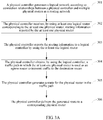
- FIG. 3A is a flowchart of another embodiment of a route advertisement method according to the present invention. This embodiment is described with reference to a network architecture shown in FIG. 1A .
- Step 301 A physical controller generates a logical network according to connection relationships between a physical controller and multiple physical routers in a routing network.
- the physical controller may generate a logical network for the routing network, where each physical device in the routing network corresponds to a logical device in the logical network, that is, the logical network includes a logical controller corresponding to the physical controller, and logical routers that correspond to the physical routers in a one-to-one mapping manner; the logical controller is connected to the logical routers, and the logical controller can communicate with the logical router based on BGP or by other means, which is not limited by this embodiment of the present invention.
- FIG. 3B shows a logical network that is generated based on a routing network shown in FIG. 1A .
- the logical network in FIG. 3B is primarily a logical network generated for an AS10, and connection relationships between the logical controller and logical routers in the logical network are shown in FIG. 3B , and are not described repeatedly herein.
- Step 302 The physical controller receives, by using at least one logical router corresponding to the at least one physical router, routing information reported by the at least one physical router.
- the destination router when a destination router needs to advertise routing information, transmits the routing information that includes a destination address to at least one physical router connected to the destination router in a routing network, where the at least one physical router is an edge router of the routing network.
- the physical controller creates a logical network, and therefore, after receiving the routing information, the at least one physical router may report the routing information to a corresponding logical router in the logical network, and the logical router then uploads the routing information to the logical controller.
- routing information that includes the address may be sent to three routers D8, D1, and D2, which are connected by using eBGP. As shown in FIG. 1A , the address is denoted by DEST_IP. After the three routers D8, D1, and D2 receive the routing information that includes the DEST_IP, with reference to FIG. 3B , the three routers D8, D1, and D2 report the routing information to corresponding logical routers D8', D1', and D2' respectively.
- Step 303 The physical controller reports the routing information to the logical controller by using the at least one logical router.
- the logical routers D8', D1', and D2' transmit the received routing information to the logical controller.
- Step 304 The physical controller obtains, by using the logical controller, a traffic path, in which the at least one physical router is used as an egress router to transmit traffic to the destination router.
- the logical controller may create a routing entry for the routing information, where the routing entry includes a mapping relationship between a router identifier of the at least one physical router and the destination address of the destination router.
- the logical controller may match a preset traffic path database according to the router identifier of the at least one physical router, where the traffic path database may include multiple preplanned traffic paths.
- Each traffic path includes physical routers in a routing network passed by the traffic transmitted between a source router and the destination router, and a direction of transmission between the physical routers.
- the logical controller may obtain a traffic path, in which the at least one physical router is used as an egress router to transmit traffic to the destination router, from the traffic path database according to a matching result.
- a process of obtaining a traffic path by the logical controller in this step is consistent with the example described in the foregoing step 202 and step 203 with reference to FIG. 1A , and is not detailed repeatedly herein.
- Step 305 The physical controller generates a route for the physical router in the traffic path.
- a first route generation manner in this step may be: the physical controller generates, by using the logical controller, a route for the physical router in the obtained traffic path.
- a specific generation process is consistent with the example described in the foregoing step 205 with reference to FIG. 1A , and is not repeated herein.
- a second route generation manner in this step may be: the physical controller delivers the routing information to multiple logical routers by using the logical controller, so that a logical router corresponding to the physical router in the obtained traffic path generates the route for the physical router in the traffic path.
- the logical router D6' corresponding to the physical router D6 may generate a route for the physical router D6 according to the received routing information and the planned traffic path. Assuming that the traffic path is still D6 -> P4 -> P2 -> D1, the route generated by the logical router D6' is "P4".
- Step 306 The physical controller delivers the generated route to a corresponding physical router.
- the physical controller may deliver, by using the logical controller, the route to the logical router corresponding to the physical router in the traffic path, where the route is generated for the physical router in the traffic path, and then the logical router forwards the generated route to the physical router corresponding to the logical router.
- the route generated by the logical controller for the physical router P4 is "P2”
- the route "P2” is delivered to the logical router P4'
- the logical router P4' forwards the route "P2" to the physical router P4.
- the physical controller may deliver the generated route to the physical router in the traffic path by using the logical router corresponding to the physical router in the traffic path.
- the logical router P4' may deliver the route "P2" to the physical router P4 directly.
- multiple traffic paths to a same destination address can be preplanned as required, where the multiple traffic paths have different egress routers, which prevents an egress router from being congested by traffic transmitted to the same destination address.
- the physical controller may directly generate a route for each router in a traffic path according to the traffic path, that is, generate a next-hop route for each router in the traffic path, and therefore, a router receiving the traffic may transmit the traffic to its next-hop router directly according to the route of the router without a need of recalculation, which improves performance of a routing network.
- the present invention further provides embodiments of a route advertisement system and a controller.
- FIG. 4 is a block diagram of an embodiment of a route advertisement system according to the present invention.
- the route advertisement system is applied to a BGP-based routing network, and includes a physical controller 410 and multiple physical routers 420 connected to the physical controller 410.
- FIG. 4 shows only five physical routers 420. In a practical application, the number of physical routers 420 may be set flexibly according to different routing network planning, which is not limited by the embodiment of the present invention.
- the physical router 420 is configured to receive routing information reported by a destination router connected to the physical router, where the routing information includes a destination address of the destination router.
- the physical controller 410 is configured to receive routing information reported by at least one physical router of the multiple physical routers 420, obtain a traffic path in which the at least one physical router is used as an egress router to transmit traffic to the destination router, generate a route for the physical router in the traffic path, and deliver the generated route to a corresponding physical router.
- FIG. 5 is a block diagram of an embodiment of a controller according to the present invention, where the controller serves as a physical controller and is applied to a BGP-based routing network, where the routing network further includes multiple physical routers connected to the physical controller.
- the controller includes a receiving unit 510, an obtaining unit 520, a generating unit 530, and an advertising unit 540.
- the receiving unit 510 is configured to receive routing information reported by at least one physical router of the multiple physical routers, where the routing information includes a destination address of a destination router connected to the at least one physical router.
- the obtaining unit 520 is configured to obtain a traffic path for transmitting traffic to the destination router by using the at least one physical router as an egress router.
- the generating unit 530 is configured to generate a route for the physical router in the traffic path obtained by the obtaining unit 520.
- the advertising unit 540 is configured to deliver the route generated by the generating unit 530 to a corresponding physical router.
- FIG. 6 is a block diagram of another embodiment of a controller according to the present invention, where the controller serves as a physical controller and is applied to a BGP-based routing network, where the routing network further includes multiple physical routers connected to the physical controller.
- the controller includes a receiving unit 610, a creating unit 620, an obtaining unit 630, a generating unit 640, and an advertising unit 650.
- the receiving unit 610 is configured to receive routing information reported by at least one physical router of the multiple physical routers, where the routing information includes a destination address of a destination router connected to the at least one physical router.
- the creating unit 620 is configured to create a routing entry for the routing information received by the receiving unit 610, where the routing entry includes a mapping relationship between a router identifier of the at least one physical router and the destination address.
- the obtaining unit 630 is configured to obtain a traffic path in which the at least one physical router is used as an egress router to transmit traffic to the destination router.
- the generating unit 640 is configured to generate a route for the physical router in the traffic path obtained by the obtaining unit 630.
- the advertising unit 650 is configured to deliver the route generated by the generating unit 640 to a corresponding physical router.
- the obtaining unit 630 may include:
- FIG. 7 is a block diagram of another embodiment of a controller according to the present invention, where the controller serves as a physical controller and is applied to a BGP-based routing network, where the routing network further includes multiple physical routers connected to the physical controller.
- the controller includes a logical unit 710, a receiving unit 720, an obtaining unit 730, a generating unit 740, and an advertising unit 750.
- the logical unit 710 is configured to generate a logical network according to connection relationships between the physical controller and the multiple physical routers in the routing network, where a logical controller in the logical network is connected to multiple logical routers, the logical controller corresponds to the physical controller, and each of the logical routers corresponds to one of the physical routers.
- the receiving unit 720 is configured to receive, by using at least one logical router corresponding to the at least one physical router, routing information reported by the at least one physical router, and report the routing information to the logical controller by using the at least one logical router.
- the obtaining unit 730 is configured to obtain a traffic path in which the at least one physical router is used as an egress router to transmit traffic to the destination router.
- the generating unit 740 is configured to generate a route for the physical router in the traffic path obtained by the obtaining unit 730.
- the advertising unit 750 is configured to deliver the route generated by the generating unit 740 to a corresponding physical router.
- FIG. 8 is a block diagram of another embodiment of a controller according to the present invention, where the controller serves as a physical controller and is applied to a BGP-based routing network, where the routing network further includes multiple physical routers connected to the physical controller.
- the controller includes a network interface 810 and a processor 820.
- the network interface 810 is configured to receive routing information reported by at least one physical router of the multiple physical routers, where the routing information includes a destination address of a destination router connected to the at least one physical router.
- the processor 820 is configured to obtain a traffic path in which the at least one physical router is used as an egress router to transmit traffic to the destination router, generate a route for the physical router in the traffic path, and deliver the generated route to a corresponding physical router through the network interface.
- a physical controller in a BGP-based routing network is connected to multiple physical routers, and the physical controller receives routing information reported by at least one physical router in the multiple physical routers, obtains a traffic path in which the at least one physical router is used as an egress router to transmit traffic to the destination router, generates a route for the physical router in the traffic path, and delivers the generated route to a corresponding physical router.
- multiple traffic paths to a same destination address can be preplanned as required, where the multiple traffic paths have different egress routers, which prevents an egress router from being congested by traffic transmitted to the same destination address.
- the physical controller may directly generate a route for each router in a traffic path according to the traffic path, that is, generate a next-hop route for each router in the traffic path, and therefore, a router receiving the traffic may transmit the traffic to its next-hop router directly according to the route of the router without a need of recalculation, which improves performance of a routing network.
- the software product is stored in a storage medium, such as a ROM/RAM, a magnetic disk, or an optical disc, and includes several instructions for instructing a computer device (which may be a personal computer, a server, a network device, or the like) to perform the methods described in the embodiments or some parts of the embodiments of the present invention.
- a computer device which may be a personal computer, a server, a network device, or the like
Landscapes
- Engineering & Computer Science (AREA)
- Computer Networks & Wireless Communication (AREA)
- Signal Processing (AREA)
- Data Exchanges In Wide-Area Networks (AREA)
Description
- The present invention relates to the field of network communications technologies, and in particular, to a route advertisement method, a system, and a controller.
- An autonomous system (AS) generally includes multiple routers, and the routers communicate by using the Border Gateway Protocol (BGP). BGP is a dynamic routing protocol deployed within an AS and between ASs, and is primarily used to exchange routing information and construct a propagation path to prevent generation of a routing loop. A router within an AS is also referred to as a peer (Peer). To ensure connectivity between routers, a full connection needs to be established between the routers, that is, each router is connected to other routers.
- However, when an AS has a large number of routers, the number of connections established between the routers is also very large accordingly, and a large quantity of network resources are consumed in establishing these connections. In the prior art, in order to reduce the number of connections between routers, a router within an AS is configured as a Route Reflector (RR), and other routers except the RR are referred to as clients (Client). A connection is established between the RR and each client, but no connection needs to be established between clients. The RR reflects routing information between the clients. When the RR receives routes reported by multiple clients that have a same destination address and serve as egress routers, the RR selects one egress router from the multiple egress routers, and sends a route of the selected one router to every client.
- The prior art has the following disadvantages: because the RR selects only one egress router and sends the route of the egress router to all clients, when any client receives traffic that is transmitted to a router corresponding to the destination address, the client needs to calculate a next-hop route of the client and finally route the traffic to the one egress router, which tends to cause congestion of the egress router and degrades performance of a routing network.
-
US 2011/310864 A1 (GAGE WILLIAM ANTHONY [CA]) 22 December 2011 (2011-12-22) discloses methods, devices, and systems for information distribution in a wireless communication system. In one embodiment, a method of information distribution in a wireless communication system comprises receiving an information advertisement signal by a propagator node, wherein said information advertisement signal identifies information available from a distributor node; storing said information advertisement signal by said propagator node in a distributor routing table; and forwarding said information advertisement signal by said propagator node to another propagator node, a selector node, or both. - Embodiments of the present invention provide a route advertisement method, system and controller to resolve a problem in the prior art that advertised routes are likely to cause congestion at a route egress and thereby lead to low routing performance of a network.
- To resolve the foregoing technical problem, the embodiments of the present invention disclose the following technical solutions:
- According to a first aspect, a route advertisement method is provided, where the method is applied to a routing network which is based on Border Gateway Protocol BGP, a physical controller in the routing network is connected to multiple physical routers, and the method includes:
- receiving, by the physical controller, routing information reported by at least one physical router of the multiple physical routers, where the routing information includes a destination address of a destination router connected to the at least one physical router;
- obtaining, by the physical controller, a traffic path in which the at least one physical router is used as an egress router to transmit traffic to the destination router;
- generating, by the physical controller, a route for a physical router in the traffic path; and
- delivering, by the physical controller, the generated route to a corresponding physical router.
- With reference to the first aspect, in a first possible implementation manner of the first aspect, after the receiving, by the physical controller, routing information reported by at least one physical router of the multiple physical routers, the method further includes:
- creating, by the physical controller, a routing entry for the routing information, where the routing entry includes a mapping relationship between a router identifier of the at least one physical router and the destination address;
- the obtaining, by the physical controller, a traffic path in which the at least one physical router is used as an egress router to transmit traffic to the destination router includes:
- matching, by the physical controller, a set traffic path database according to the router identifier of the at least one physical router; and
- obtaining a traffic path, in which the at least one physical router is used as an egress router to transmit traffic to the destination router, from the traffic path database according to a matching result.
- With reference to the first aspect or the first possible implementation manner of the first aspect, in a second possible implementation manner of the first aspect, before the receiving, by the physical controller, routing information reported by at least one physical router of the multiple physical routers, the method further includes:
- generating, by the physical controller, a logical network according to connection relationships between the physical controller and the multiple physical routers in the routing network, where a logical controller in the logical network is connected to multiple logical routers, the logical controller corresponds to the physical controller, and each of the logical routers corresponds to one of the physical routers; and
- the receiving, by the physical controller, routing information reported by at least one physical router of the multiple physical routers includes:
- receiving, by the physical controller by using at least one logical router corresponding to the at least one physical router, the routing information reported by the at least one physical router; and
- reporting, by the physical controller, the routing information to the logical controller by using the at least one logical router.
- With reference to the second possible implementation manner of the first aspect, in a third possible implementation manner of the first aspect, the generating, by the physical controller, a route for a physical router in the traffic path includes:
- generating, by the physical controller, the route for the physical router in the traffic path by using the logical controller; and
- the delivering, by the physical controller, the generated route to a corresponding physical router includes:
- delivering, by the physical controller by using the logical controller, the route to a logical router corresponding to the physical router in the traffic path, where the route is generated for the physical router in the traffic path; and
- forwarding, by the physical controller by using the logical router, the generated route to the physical router corresponding to the logical router.
- With reference to the second possible implementation manner of the first aspect, in a fourth possible implementation manner of the first aspect, the generating, by the physical controller, a route for a physical router in the traffic path includes:
- delivering, by the physical controller, the routing information to the multiple logical routers by using the logical controller, so that a logical router corresponding to the physical router in the traffic path generates the route for the physical router in the traffic path; and
- the delivering, by the physical controller, the generated route to a corresponding physical router includes:
- delivering, by the physical controller, the generated route to the physical router in the traffic path by using the logical router corresponding to the physical router in the traffic path.
- According to a second aspect, a controller is provided, where the controller serves as a physical controller and is applied to a routing network which is based on Border Gateway Protocol BGP, where the routing network further includes multiple physical routers connected to the physical controller, and the controller includes:
- a receiving unit, configured to receive routing information reported by at least one physical router of the multiple physical routers, where the routing information includes a destination address of a destination router connected to the at least one physical router;
- an obtaining unit, configured to obtain a traffic path in which the at least one physical router is used as an egress router to transmit traffic to the destination router;
- a generating unit, configured to generate a route for a physical router in the traffic path obtained by the obtaining unit; and
- an advertising unit, configured to deliver the route generated by the generating unit to a corresponding physical router.
- With reference to the second aspect, in a first possible implementation manner of the second aspect, the controller further includes:
- a creating unit, configured to create a routing entry for the routing information received by the receiving unit, where the routing entry includes a mapping relationship between a router identifier of the at least one physical router and the destination address; and
- the obtaining unit includes:
- a path matching subunit, configured to match a set traffic path database according to the router identifier of the at least one physical router; and
- a path obtaining subunit, configured to obtain a traffic path, in which the at least one physical router is used as an egress router to transmit traffic to the destination router, from the traffic path database according to a matching result of the path matching subunit.
- With reference to the second aspect or the first possible implementation manner of the second aspect, in a second possible implementation manner of the first aspect, the controller further includes:
- a logical unit, configured to generate a logical network according to connection relationships between the physical controller and the multiple physical routers in the routing network, where a logical controller in the logical network is connected to multiple logical routers, the logical controller corresponds to the physical controller, and each of the logical routers corresponds to one of the physical routers; and
- the receiving unit is specifically configured to receive, by using at least one logical router corresponding to the at least one physical router, the routing information reported by the at least one physical router, and report the routing information to the logical controller by using the at least one logical router.
- With reference to the second possible implementation manner of the second aspect, in a second possible implementation manner of the second aspect, the generating unit is specifically configured to generate the route for the physical router in the traffic path by using the logical controller; and
the advertising unit is specifically configured to: deliver, by using the logical controller, the route to a logical router corresponding to the physical router in the traffic path, where the route is generated for the physical router in the traffic path, and
forward, by using the logical router, the generated route to the physical router corresponding to the logical router. - With reference to the second possible implementation manner of the second aspect, in a fourth possible implementation manner of the second aspect, the generating unit is specifically configured to deliver the routing information to the multiple logical routers by using the logical controller, so that a logical router corresponding to the physical router in the traffic path generates the route for the physical router in the traffic path; and
the advertising unit is specifically configured to deliver the generated route to the physical router in the traffic path by using the logical router corresponding to the physical router in the traffic path. - According to a third aspect, a route advertisement system is provided, where the system is applied to a routing network which is based on Border Gateway Protocol BGP, and the system includes a physical controller according to the second aspect or any possible implementation manner of the second aspect and multiple physical routers connected to the physical controller, where
the physical router is configured to receive routing information reported by a destination router connected to the physical router, where the routing information includes a destination address of the destination router. - With reference to the second possible implementation manner of the third aspect, in a third possible implementation manner of the third aspect, the generating unit is specifically configured to generate the route for the physical router in the traffic path by using the logical controller; and
the advertising unit is specifically configured to: deliver, by using the logical controller, the route to a logical router corresponding to the physical router in the traffic path, where the route is generated for the physical router in the traffic path, and forward, by using the logical router, the generated route to the physical router corresponding to the logical router. - With reference to the second possible implementation manner of the third aspect, in a fourth possible implementation manner of the third aspect, the generating unit is specifically configured to deliver the routing information to the multiple logical routers by using the logical controller, so that a logical router corresponding to the physical router in the traffic path generates the route for the physical router in the traffic path; and
the advertising unit is specifically configured to deliver the generated route to the physical router in the traffic path by using the logical router corresponding to the physical router in the traffic path. - According to a fourth aspect, a controller is provided, where the controller serves as a physical controller and is applied to a routing network which is based on Border Gateway Protocol BGP, where the routing network further includes multiple physical routers connected to the physical controller, and the controller includes a network interface and a processor, where
the network interface is configured to receive routing information reported by at least one physical router of the multiple physical routers, where the routing information includes a destination address of a destination router connected to the at least one physical router; and
the processor is configured to obtain a traffic path in which the at least one physical router is used as an egress router to transmit traffic to the destination router, generate a route for a physical router in the traffic path, and deliver the generated route to a corresponding physical router through the network interface. - With reference to the fourth aspect, in a first possible implementation manner of the fourth aspect, the processor is further configured to create a routing entry for the routing information, where the routing entry includes a mapping relationship between a router identifier of the at least one physical router and the destination address; and
the processor is specifically configured to match a set traffic path database according to the router identifier of the at least one physical router, and obtain a traffic path, in which the at least one physical router is used as an egress router to transmit traffic to the destination router, from the traffic path database according to a matching result. - With reference to the fourth aspect or the first possible implementation manner of the fourth aspect, in a second possible implementation manner of the fourth aspect, the processor is further configured to generate a logical network according to connection relationships between the physical controller and the multiple physical routers in the routing network, where a logical controller in the logical network is connected to multiple logical routers, the logical controller corresponds to the physical controller, and each of the logical routers corresponds to one of the physical routers; and
the processor is specifically configured to receive, by using at least one logical router corresponding to the at least one physical router, the routing information reported by the at least one physical router, and report the routing information to the logical controller by using the at least one logical router. - With reference to the second possible implementation manner of the fourth aspect, in a third possible implementation manner of the fourth aspect, the processor is specifically configured to generate the route for the physical router in the traffic path by using the logical controller, deliver, by using the logical controller, the route to a logical router corresponding to the physical router in the traffic path, where the route is generated for the physical router in the traffic path, and forward, through the network interface by using the logical router, the generated route to the physical router corresponding to the logical router.
- With reference to the second possible implementation manner of the fourth aspect, in a fourth possible implementation manner of the fourth aspect, the processor is specifically configured to deliver the routing information to the multiple logical routers by using the logical controller, so that a logical router corresponding to the physical router in the traffic path generates the route for the physical router in the traffic path; and deliver the generated route to the physical router in the traffic path through the network interface by using the logical router corresponding to the physical router in the traffic path.
- In the embodiments of the present invention, a physical controller in a BGP-based routing network is connected to multiple physical routers, and the physical controller receives routing information reported by at least one physical router in the multiple physical routers, obtains a traffic path in which the at least one physical router is used as an egress router to transmit traffic to the destination router, generates a route for the physical router in the traffic path, and delivers the generated route to a corresponding physical router. By applying the embodiments of the present invention, multiple traffic paths to a same destination address can be preplanned as required, where the multiple traffic paths have different egress routers, which prevents an egress router from being congested by traffic transmitted to the same destination address. In addition, the physical controller may directly generate a route for each router in a traffic path according to the traffic path, that is, generate a next-hop route for each router in the traffic path, and therefore, a router receiving the traffic may transmit the traffic to its next-hop router directly according to the route of the router without a need of recalculation, which improves performance of a routing network.
- To describe the technical solutions in the embodiments of the present invention or in the prior art more clearly, the following briefly introduces the accompanying drawings required for describing the embodiments or the prior art. Apparently, the accompanying drawings in the following description show merely some embodiments of the present invention, and a person of ordinary skill in the art may still derive other drawings from these accompanying drawings without creative efforts.
-
FIG. 1A is a schematic diagram of a scenario of a routing network to which an embodiment of the present invention is applied; -
FIG. 1B is a flowchart of an embodiment of a route advertisement method according to the present invention; -
FIG. 2 is a flowchart of another embodiment of a route advertisement method according to the present invention; -
FIG. 3A is a flowchart of another embodiment of a route advertisement method according to the present invention; -
FIG. 3B is a schematic diagram of a logical network that is generated based on a routing network shown inFIG. 1A ; -
FIG. 4 is a block diagram of an embodiment of a route advertisement system according to the present invention; -
FIG. 5 is a block diagram of an embodiment of a controller according to the present invention; -
FIG. 6 is a block diagram of another embodiment of a controller according to the present invention; -
FIG. 7 is a block diagram of another embodiment of a controller according to the present invention; and -
FIG. 8 is a block diagram of another embodiment of a controller according to the present invention. - To enable a person skilled in the art to better understand technical solutions in embodiments of the present invention, and make the foregoing objectives, features, and advantages of the embodiments of the present invention clearer and more comprehensible, the following describes the technical solutions of the embodiments of the present invention in more detail with reference to accompanying drawings.
- Referring to
FIG. 1A, FIG. 1A is a schematic diagram of a scenario of a routing network to which an embodiment of the present invention is applied. - The routing network in
FIG. 1A is a BGP-based routing network having four ASs: AS1, AS10, AS2, and AS3. The AS10 includes a controller and multiple routers connected to the controller by using internal BGP (internal BGP, iBGP), and the routers include D1, D2, D3, D4, D5, D6, D7, D8, P1, P2, P3, and P4. The routers may be not directly connected to each other. A dotted line between routers inFIG. 1A only indicates that traffic can be transmitted between the routers according to a routing relationship. The AS1 includes a router A1, the AS2 includes a router A2, and the AS3 includes a router A3. The A1 is connected to edge routers D8, D1, and D2 in the AS10 by using external BGP eBGP), the A2 is connected to an edge router D6 in the AS10 by using eBGP, and the A3 is connected to an edge router D5 in the AS10 by using eBGP. The controller and the routers shown inFIG. 1A are all physical devices; therefore, they may also be referred to as a physical controller and physical routers in the embodiments of the present invention. - Referring to
FIG. 1B, FIG. 1B is a flowchart of an embodiment of a route advertisement method according to the present invention, and the method includes: - Step 101: A physical controller receives routing information reported by at least one physical router of multiple physical routers connected to the physical controller, where the routing information includes a destination address of a destination router connected to the at least one physical router.
- In this embodiment, when a destination router needs to advertise routing information, the destination router transmits the routing information that includes a destination address to at least one physical router connected to the destination router in a routing network, where the at least one physical router is an edge router of the routing network. After receiving the routing information advertised by the destination router, the at least one physical router reports the routing information to the physical controller.
- Step 102: The physical controller obtains a traffic path in which the at least one physical router is used as an egress router to transmit traffic to the destination router.
- After receiving the routing information reported by the at least one physical router, the physical controller may create a routing entry for the routing information. The routing entry includes a mapping relationship between a router identifier of the at least one physical router and the destination address of the destination router. The physical controller may match a preset traffic path database according to the router identifier of the at least one physical router, where the traffic path database may include multiple preplanned traffic paths. Each traffic path includes physical routers in a routing network passed by the traffic transmitted between a source router and the destination router, and a direction of transmission between the physical routers. The physical controller can obtain a traffic path, in which the at least one physical router is used as an egress router to transmit traffic to the destination router, from the traffic path database according to a matching result.
- Step 103: The physical controller generates a route for the physical router in the traffic path.
- In this embodiment, because each traffic path includes physical routers in the routing network passed by the traffic transmitted between the source router and the destination router, and the direction of transmission between the physical routers, the physical controller generates a route for each router in the transmission path, where the route identifies a next-hop router of each of the routers.
- Step 104: The physical controller delivers the generated route to a corresponding physical router.
- It can be seen from the foregoing embodiment that, in the embodiment, multiple traffic paths to a same destination address can be preplanned as required, where the multiple traffic paths have different egress routers, which prevents an egress router from being congested by traffic transmitted to the same destination address. In addition, the physical controller may directly generate a route for each router in a traffic path according to the traffic path, that is, generate a next-hop route for each router in the traffic path, and therefore, a router receiving the traffic may transmit the traffic to its next-hop router directly according to the route of the router without a need of recalculation, which improves performance of a routing network.
- Referring to
FIG. 2, FIG. 2 is a flowchart of another embodiment of a route advertisement method according to the present invention. This embodiment is described with reference to a network architecture shown inFIG. 1A . - Step 201: A physical controller receives routing information reported by at least one physical router of multiple physical routers connected to the physical controller, where the routing information includes a destination address of a destination router connected to the at least one physical router.
- In this embodiment, when a destination router needs to advertise routing information, the destination router transmits the routing information that includes a destination address to at least one physical router connected to the destination router in a routing network, where the at least one physical router is an edge router of the routing network. After receiving the routing information advertised by the destination router, the at least one physical router reports the routing information to the physical controller.
- With reference to
FIG. 1A , when traffic needs to be transmitted to a router A1 in an AS1, the router A1 serves as a destination router and an address of the router A1 serves as a destination address, where the destination address generally refers to an Internet Protocol (Internet Protocol, IP) address. When the router A1 advertises its address, routing information that includes the address may be sent to three routers D8, D1, and D2, which are connected by using eBGP. As shown inFIG. 1A , the address is denoted by DEST_IP. After receiving the routing information that includes the DEST_IP, the three routers D8, D1, and D2 report the routing information to the controller. - Step 202: The physical controller creates a routing entry for the routing information, where the routing entry includes a mapping relationship between a router identifier of the at least one physical router and the destination address.
- After receiving the routing information reported by the at least one physical router, the physical controller may create a routing entry for the routing information, where the routing entry includes the mapping relationship between the router identifier of the at least one physical router and the destination address of the destination router. With reference to
FIG. 1A , after receiving the routing information reported by the three routers D8, D1, and D2, the physical controller creates three routing entries for the routing information, as listed in Table 1 below:Table 1 Destination address Physical router identifier DEST_IP D8 DEST_IP D1 DEST_IP D2 - Step 203: The physical controller matches a set traffic path database according to the router identifier of the at least one physical router.
- In this embodiment, the traffic path database may include multiple preplanned traffic paths, and each traffic path includes physical routers in the routing network passed by the traffic transmitted between a source router and the destination router, and a direction of transmission between the physical routers.
- With reference to
FIG. 1A , assuming that the traffic path database stores two preplanned traffic paths in which a router A1 is used as the destination router, a router A2 in an AS2 accesses the router A1 in the AS1 by using a traffic path: D6 -> P4 -> P2 -> D1, where the router A2 serves as a source router, and its source address is SRC_IP1; a router A3 in an AS3 accesses the router A1 in the AS1 by using a traffic path: D5 -> P3 -> D2, where the router A3 serves as the source router, and its source address is SRC_IP2. It can be learned from the foregoing description that, compared with the prior art, a traffic path can be preplanned in the present invention, and therefore traffic can be transmitted to the router A1 by using multiple egress routers in an AS10 that are connected to the router A1, instead of using only one egress router. - Step 204: The physical controller obtains a traffic path, in which the at least one physical router is used as an egress router to transmit traffic to the destination router, from the traffic path database according to a matching result.
- With reference to
FIG. 1A , when the physical controller creates a routing entry listed in Table 1, traffic paths in the traffic path database are matched according to the physical router identifiers D8, D1, and D2. It can be learned from the foregoing example that the router identifier D1 and two traffic paths corresponding to D1 are matched. - Step 205: The physical controller generates a route for the physical router in the traffic path.
- For the traffic path D6 -> P4 -> P2 -> D1 in the foregoing example, routes generated by the physical controller for physical routers in the traffic path are listed in the Table 2 below:
Table 2 Destination address Current router identifier Next-hog router identifier DEST_IP P2 D1 DEST_IP P4 P2 DEST_IP D6 P4 - Similarly, for the traffic path D5 -> P3 -> D2 in the foregoing example, routes generated by the physical controller for physical routers in the traffic path are listed in the Table 3 below:
Table 3 Destination address Current router identifier Next-hop router identifier DEST_IP P3 D2 DEST_IP D5 P3 - Step 206: The physical controller delivers the generated route to a corresponding physical router.
- By using the foregoing Table 1 as an example, the physical controller delivers a route "P4" generated for a physical router D6 to the physical router D6, delivers a route "P2" generated for a physical router P4 to the physical router P4, and delivers a route "D1" generated for a physical router P2 to the physical router P2.
- It can be seen from the foregoing embodiment that: in the embodiment, multiple traffic paths to a same destination address can be preplanned as required, where the multiple traffic paths have different egress routers, which prevents an egress router from being congested by traffic transmitted to the same destination address. In addition, the physical controller may directly generate a route for each router in a traffic path according to the traffic path, that is, generate a next-hop route for each router in the traffic path, and therefore, a router receiving the traffic may transmit the traffic to its next-hop router directly according to the route of the router without a need of recalculation, which improves performance of a routing network.
- Referring to
FIG. 3A, FIG. 3A is a flowchart of another embodiment of a route advertisement method according to the present invention. This embodiment is described with reference to a network architecture shown inFIG. 1A . - Step 301: A physical controller generates a logical network according to connection relationships between a physical controller and multiple physical routers in a routing network.
- In this embodiment, the physical controller may generate a logical network for the routing network, where each physical device in the routing network corresponds to a logical device in the logical network, that is, the logical network includes a logical controller corresponding to the physical controller, and logical routers that correspond to the physical routers in a one-to-one mapping manner; the logical controller is connected to the logical routers, and the logical controller can communicate with the logical router based on BGP or by other means, which is not limited by this embodiment of the present invention.
- Referring to
FIG. 3B, FIG. 3B shows a logical network that is generated based on a routing network shown inFIG. 1A . The logical network inFIG. 3B is primarily a logical network generated for an AS10, and connection relationships between the logical controller and logical routers in the logical network are shown inFIG. 3B , and are not described repeatedly herein. - Step 302: The physical controller receives, by using at least one logical router corresponding to the at least one physical router, routing information reported by the at least one physical router.
- In this embodiment, when a destination router needs to advertise routing information, the destination router transmits the routing information that includes a destination address to at least one physical router connected to the destination router in a routing network, where the at least one physical router is an edge router of the routing network. In this embodiment, the physical controller creates a logical network, and therefore, after receiving the routing information, the at least one physical router may report the routing information to a corresponding logical router in the logical network, and the logical router then uploads the routing information to the logical controller.
- With reference to
FIG. 1A , when the router A1 advertises its address, routing information that includes the address may be sent to three routers D8, D1, and D2, which are connected by using eBGP. As shown inFIG. 1A , the address is denoted by DEST_IP. After the three routers D8, D1, and D2 receive the routing information that includes the DEST_IP, with reference toFIG. 3B , the three routers D8, D1, and D2 report the routing information to corresponding logical routers D8', D1', and D2' respectively. - Step 303: The physical controller reports the routing information to the logical controller by using the at least one logical router.
- With reference to
FIG. 3B , the logical routers D8', D1', and D2' transmit the received routing information to the logical controller. - Step 304: The physical controller obtains, by using the logical controller, a traffic path, in which the at least one physical router is used as an egress router to transmit traffic to the destination router.
- In this embodiment, after receiving the routing information reported by the at least one logical router, the logical controller may create a routing entry for the routing information, where the routing entry includes a mapping relationship between a router identifier of the at least one physical router and the destination address of the destination router.
- The logical controller may match a preset traffic path database according to the router identifier of the at least one physical router, where the traffic path database may include multiple preplanned traffic paths. Each traffic path includes physical routers in a routing network passed by the traffic transmitted between a source router and the destination router, and a direction of transmission between the physical routers. The logical controller may obtain a traffic path, in which the at least one physical router is used as an egress router to transmit traffic to the destination router, from the traffic path database according to a matching result.
- A process of obtaining a traffic path by the logical controller in this step is consistent with the example described in the foregoing
step 202 and step 203 with reference toFIG. 1A , and is not detailed repeatedly herein. - Step 305: The physical controller generates a route for the physical router in the traffic path.
- A first route generation manner in this step may be: the physical controller generates, by using the logical controller, a route for the physical router in the obtained traffic path. A specific generation process is consistent with the example described in the foregoing
step 205 with reference toFIG. 1A , and is not repeated herein. - A second route generation manner in this step may be: the physical controller delivers the routing information to multiple logical routers by using the logical controller, so that a logical router corresponding to the physical router in the obtained traffic path generates the route for the physical router in the traffic path. For example, with reference to
FIG. 1A , the logical router D6' corresponding to the physical router D6 may generate a route for the physical router D6 according to the received routing information and the planned traffic path. Assuming that the traffic path is still D6 -> P4 -> P2 -> D1, the route generated by the logical router D6' is "P4". - Step 306: The physical controller delivers the generated route to a corresponding physical router.
- With reference to the first routing manner in
step 305, the physical controller may deliver, by using the logical controller, the route to the logical router corresponding to the physical router in the traffic path, where the route is generated for the physical router in the traffic path, and then the logical router forwards the generated route to the physical router corresponding to the logical router. With reference toFIG. 3B , for example, when the route generated by the logical controller for the physical router P4 is "P2", the route "P2" is delivered to the logical router P4', and the logical router P4' forwards the route "P2" to the physical router P4. - With reference to the second route generation manner in
step 305, the physical controller may deliver the generated route to the physical router in the traffic path by using the logical router corresponding to the physical router in the traffic path. With reference toFIG. 3B , after generating the route "P2" for the physical router P4, the logical router P4' may deliver the route "P2" to the physical router P4 directly. - It can be seen from the foregoing embodiment that, in the embodiment, multiple traffic paths to a same destination address can be preplanned as required, where the multiple traffic paths have different egress routers, which prevents an egress router from being congested by traffic transmitted to the same destination address. In addition, the physical controller may directly generate a route for each router in a traffic path according to the traffic path, that is, generate a next-hop route for each router in the traffic path, and therefore, a router receiving the traffic may transmit the traffic to its next-hop router directly according to the route of the router without a need of recalculation, which improves performance of a routing network.
- Corresponding to the embodiments of a route advertisement method according to the present invention, the present invention further provides embodiments of a route advertisement system and a controller.
- Referring to
FIG. 4, FIG. 4 is a block diagram of an embodiment of a route advertisement system according to the present invention. - The route advertisement system is applied to a BGP-based routing network, and includes a
physical controller 410 and multiplephysical routers 420 connected to thephysical controller 410. For ease of illustration,FIG. 4 shows only fivephysical routers 420. In a practical application, the number ofphysical routers 420 may be set flexibly according to different routing network planning, which is not limited by the embodiment of the present invention. - The
physical router 420 is configured to receive routing information reported by a destination router connected to the physical router, where the routing information includes a destination address of the destination router. - The
physical controller 410 is configured to receive routing information reported by at least one physical router of the multiplephysical routers 420, obtain a traffic path in which the at least one physical router is used as an egress router to transmit traffic to the destination router, generate a route for the physical router in the traffic path, and deliver the generated route to a corresponding physical router. - In an optional implementation manner:
- the
physical controller 410 may be further configured to create a routing entry for the routing information after receiving the routing information reported by the at least one physical router of the multiple physical routers, where the routing entry includes a mapping relationship between a router identifier of the at least one physical router and the destination address; and - the
physical controller 410 may be specifically configured to match a set traffic path database according to the router identifier of the at least one physical router, and obtain a traffic path, in which the at least one physical router is used as an egress router to transmit traffic to the destination router, from the traffic path database according to a matching result. - In another optional implementation manner:
- the
physical controller 410 may be further configured to generate a logical network according to connection relationships between the physical controller and the multiple physical routers in the routing network, where a logical controller in the logical network is connected to multiple logical routers, the logical controller corresponds to the physical controller, and each of the logical routers corresponds to one of the physical routers; and - the
physical controller 410 may be specifically configured to receive, by using at least one logical router corresponding to the at least one physical router, the routing information reported by the at least one physical router, and report the routing information to the logical controller by using the at least one logical router. - In another optional implementation manner:
- the
physical controller 410 may be specifically configured to generate the route for the physical router in the traffic path by using the logical controller, deliver, by using the logical controller, the route to the logical router corresponding to the physical router in the traffic path, where the route is generated for the physical router in the traffic path, and forward, by using the logical router, the generated route to the physical router corresponding to the logical router. - In another optional implementation manner:
- the physical controller may be specifically configured to deliver the routing information to the multiple logical routers by using the logical controller, so that a logical router corresponding to the physical router in the traffic path generates the route for the physical router in the traffic path; and deliver the generated route to the physical router in the traffic path by using the logical router corresponding to the physical router in the traffic path.
- Referring to
FIG. 5, FIG. 5 is a block diagram of an embodiment of a controller according to the present invention, where the controller serves as a physical controller and is applied to a BGP-based routing network, where the routing network further includes multiple physical routers connected to the physical controller. - The controller includes a receiving
unit 510, an obtainingunit 520, agenerating unit 530, and anadvertising unit 540. - The receiving
unit 510 is configured to receive routing information reported by at least one physical router of the multiple physical routers, where the routing information includes a destination address of a destination router connected to the at least one physical router. - The obtaining
unit 520 is configured to obtain a traffic path for transmitting traffic to the destination router by using the at least one physical router as an egress router. - The generating
unit 530 is configured to generate a route for the physical router in the traffic path obtained by the obtainingunit 520. - The
advertising unit 540 is configured to deliver the route generated by the generatingunit 530 to a corresponding physical router. - Referring to
FIG. 6, FIG. 6 is a block diagram of another embodiment of a controller according to the present invention, where the controller serves as a physical controller and is applied to a BGP-based routing network, where the routing network further includes multiple physical routers connected to the physical controller. - The controller includes a receiving
unit 610, a creatingunit 620, an obtainingunit 630, agenerating unit 640, and anadvertising unit 650. - The receiving
unit 610 is configured to receive routing information reported by at least one physical router of the multiple physical routers, where the routing information includes a destination address of a destination router connected to the at least one physical router. - The creating
unit 620 is configured to create a routing entry for the routing information received by the receivingunit 610, where the routing entry includes a mapping relationship between a router identifier of the at least one physical router and the destination address. - The obtaining
unit 630 is configured to obtain a traffic path in which the at least one physical router is used as an egress router to transmit traffic to the destination router. - The generating
unit 640 is configured to generate a route for the physical router in the traffic path obtained by the obtainingunit 630. - The
advertising unit 650 is configured to deliver the route generated by the generatingunit 640 to a corresponding physical router. - Optionally, the obtaining
unit 630 may include: - a path matching subunit, configured to match a set traffic path database according to the router identifier of the at least one physical router; and
- a path obtaining subunit, configured to obtain a traffic path, in which the at least one physical router is used as an egress router to transmit traffic to the destination router, from the traffic path database according to a matching result of the path matching subunit.
- Referring to
FIG. 7, FIG. 7 is a block diagram of another embodiment of a controller according to the present invention, where the controller serves as a physical controller and is applied to a BGP-based routing network, where the routing network further includes multiple physical routers connected to the physical controller. - The controller includes a
logical unit 710, a receivingunit 720, an obtainingunit 730, agenerating unit 740, and anadvertising unit 750. - The
logical unit 710 is configured to generate a logical network according to connection relationships between the physical controller and the multiple physical routers in the routing network, where a logical controller in the logical network is connected to multiple logical routers, the logical controller corresponds to the physical controller, and each of the logical routers corresponds to one of the physical routers. - The receiving
unit 720 is configured to receive, by using at least one logical router corresponding to the at least one physical router, routing information reported by the at least one physical router, and report the routing information to the logical controller by using the at least one logical router. - The obtaining
unit 730 is configured to obtain a traffic path in which the at least one physical router is used as an egress router to transmit traffic to the destination router. - The generating
unit 740 is configured to generate a route for the physical router in the traffic path obtained by the obtainingunit 730. - The
advertising unit 750 is configured to deliver the route generated by the generatingunit 740 to a corresponding physical router. - In an optional implementation manner:
- the generating
unit 740 may be specifically configured to generate the route for the physical router in the traffic path by using the logical controller; and - the
advertising unit 750 may be specifically configured to deliver, by using the logical controller, the route to the logical router corresponding to the physical router in the traffic path, where the route is generated for the physical router in the traffic path, and forward, by using the logical router, the generated route to the physical router corresponding to the logical router. - In another optional implementation manner:
- the generating
unit 740 may be specifically configured to deliver the routing information to the multiple logical routers by using the logical controller, so that the logical router corresponding to the physical router in the traffic path generates the route for the physical router in the traffic path; and - the
advertising unit 750 may be specifically configured to deliver the generated route to the physical router in the traffic path by using the logical router corresponding to the physical router in the traffic path. - Referring to
FIG. 8, FIG. 8 is a block diagram of another embodiment of a controller according to the present invention, where the controller serves as a physical controller and is applied to a BGP-based routing network, where the routing network further includes multiple physical routers connected to the physical controller. - The controller includes a
network interface 810 and aprocessor 820. - The
network interface 810 is configured to receive routing information reported by at least one physical router of the multiple physical routers, where the routing information includes a destination address of a destination router connected to the at least one physical router. - The
processor 820 is configured to obtain a traffic path in which the at least one physical router is used as an egress router to transmit traffic to the destination router, generate a route for the physical router in the traffic path, and deliver the generated route to a corresponding physical router through the network interface. - In an optional implementation manner:
- the
processor 820 may be further configured to create a routing entry for the routing information, where the routing entry includes a mapping relationship between a router identifier of the at least one physical router and the destination address; and - the
processor 820 may be specifically configured to match a set traffic path database according to the router identifier of the at least one physical router, and obtain a traffic path, in which the at least one physical router is used as an egress router to transmit traffic to the destination router, from the traffic path database according to a matching result. - In another optional implementation manner:
- the
processor 820 may be further configured to generate a logical network according to connection relationships between the physical controller and the multiple physical routers in the routing network, where a logical controller in the logical network is connected to multiple logical routers, the logical controller corresponds to the physical controller, and each of the logical routers corresponds to one of the physical routers; and - the
processor 820 may be specifically configured to receive, by using at least one logical router corresponding to the at least one physical router, the routing information reported by the at least one physical router, and report the routing information to the logical controller by using the at least one logical router. - In another optional implementation manner:
- the
processor 820 may be specifically configured to generate the route for the physical router in the traffic path by using the logical controller, deliver, by using the logical controller, the route to the logical router corresponding to the physical router in the traffic path, where the route is generated for the physical router in the traffic path, and forward, through the network interface by using the logical router, the generated route to the physical router corresponding to the logical router. - In another optional implementation manner:
- the
processor 820 may be specifically configured to deliver the routing information to the multiple logical routers by using the logical controller, so that a logical router corresponding to the physical router in the traffic path generates the route for the physical router in the traffic path; and deliver the generated route to the physical router in the traffic path through the network interface by using the logical router corresponding to the physical router in the traffic path. - It can be seen from the foregoing embodiment that, a physical controller in a BGP-based routing network is connected to multiple physical routers, and the physical controller receives routing information reported by at least one physical router in the multiple physical routers, obtains a traffic path in which the at least one physical router is used as an egress router to transmit traffic to the destination router, generates a route for the physical router in the traffic path, and delivers the generated route to a corresponding physical router. By applying the embodiments of the present invention, multiple traffic paths to a same destination address can be preplanned as required, where the multiple traffic paths have different egress routers, which prevents an egress router from being congested by traffic transmitted to the same destination address. In addition, the physical controller may directly generate a route for each router in a traffic path according to the traffic path, that is, generate a next-hop route for each router in the traffic path, and therefore, a router receiving the traffic may transmit the traffic to its next-hop router directly according to the route of the router without a need of recalculation, which improves performance of a routing network.
- A person skilled in the art may clearly understand that the technologies in the embodiments of the present invention may be implemented by software in addition to a necessary universal hardware platform. Based on such an understanding, the technical solutions of the present invention essentially or the part contributing to the prior art may be implemented in a form of a software product. The software product is stored in a storage medium, such as a ROM/RAM, a magnetic disk, or an optical disc, and includes several instructions for instructing a computer device (which may be a personal computer, a server, a network device, or the like) to perform the methods described in the embodiments or some parts of the embodiments of the present invention.
- The embodiments in this specification are all described in a progressive manner. For the same or similar part in different embodiments, reference may be made between the embodiments. Each embodiment focuses on differences from other embodiments. Particularly, for a system embodiment, because it is basically similar to the method embodiment, the system embodiment is described briefly, and the relevant part may be obtained with reference to the description of the corresponding part in the method embodiment.
Claims (11)
- A route advertisement method, wherein the method is applied to a routing network which is based on Border Gateway Protocol, BGP, a physical controller in the routing network is connected to multiple physical routers, and the method characterised by:receiving (101), by the physical controller, routing information reported by at least one physical router of the multiple physical routers, wherein the routing information comprises a destination address of a destination router connected to the at least one physical router;obtaining (102), by the physical controller, a traffic path in which the at least one physical router is used as an egress router to transmit traffic to the destination router;generating (103), by the physical controller, a route for a physical router in the traffic path; anddelivering (104), by the physical controller, the generated route to a corresponding physical router.
- The method according to claim 1, wherein, after the receiving, by the physical controller, routing information reported by at least one physical router of the multiple physical routers, the method further comprises:creating, by the physical controller, a routing entry for the routing information, wherein the routing entry comprises a mapping relationship between a router identifier of the at least one physical router and the destination address; andthe obtaining, by the physical controller, a traffic path in which the at least one physical router is used as an egress router to transmit traffic to the destination router comprises:matching, by the physical controller, a set traffic path database according to the router identifier of the at least one physical router; andobtaining a traffic path, in which the at least one physical router is used as an egress router to transmit traffic to the destination router, from the traffic path database according to a matching result.
- The method according to claim 1 or 2, wherein, before the receiving, by the physical controller, routing information reported by at least one physical router of the multiple physical routers, the method further comprises:generating, by the physical controller, a logical network according to connection relationships between the physical controller and the multiple physical routers in the routing network, wherein a logical controller in the logical network is connected to multiple logical routers, the logical controller corresponds to the physical controller, and each of the logical routers corresponds to one of the physical routers; andthe receiving, by the physical controller, routing information reported by at least one physical router of the multiple physical routers comprises:receiving, by the physical controller by using at least one logical router corresponding to the at least one physical router, the routing information reported by the at least one physical router; andreporting, by the physical controller, the routing information to the logical controller by using the at least one logical router.
- The method according to claim 3, wherein the generating, by the physical controller, a route for a physical router in the traffic path comprises:generating, by the physical controller, the route for the physical router in the traffic path by using the logical controller; andthe delivering, by the physical controller, the generated route to a corresponding physical router comprises:delivering, by the physical controller by using the logical controller, the route to a logical router corresponding to the physical router in the traffic path, wherein the route is generated for the physical router in the traffic path; andforwarding, by the physical controller by using the logical router, the generated route to the physical router corresponding to the logical router.
- The method according to claim 3, wherein the generating, by the physical controller, a route for a physical router in the traffic path comprises:delivering, by the physical controller, the routing information to the multiple logical routers by using the logical controller, so that a logical router corresponding to the physical router in the traffic path generates the route for the physical router in the traffic path; andthe delivering, by the physical controller, the generated route to a corresponding physical router comprises:delivering, by the physical controller, the generated route to the physical router in the traffic path by using the logical router corresponding to the physical router in the traffic path.
- A controller, wherein the controller serves as a physical controller and is applied to a routing network which is based on Border Gateway Protocol, BGP, wherein the routing network further comprises multiple physical routers connected to the physical controller, and the controller characterised by:a receiving unit (510, 610, 720), configured to receive routing information reported by at least one physical router of the multiple physical routers, wherein the routing information comprises a destination address of a destination router connected to the at least one physical router;an obtaining unit (520, 630, 730), configured to obtain a traffic path in which the at least one physical router is used as an egress router to transmit traffic to the destination router;a generating unit (530, 640, 740), configured to generate a route for a physical router in the traffic path obtained by the obtaining unit (520, 630, 730); andan advertising unit (540, 650, 750), configured to deliver the route generated by the generating unit (530, 640, 740) to a corresponding physical router.
- The controller according to claim 6, wherein the controller further comprises:a creating unit (620, 740), configured to create a routing entry for the routing information received by the receiving unit (510, 610, 720), wherein the routing entry comprises a mapping relationship between a router identifier of the at least one physical router and the destination address; andthe obtaining unit (520, 630, 730) comprises:a path matching subunit, configured to match a set traffic path database according to the router identifier of the at least one physical router; anda path obtaining subunit, configured to obtain a traffic path, in which the at least one physical router is used as an egress router to transmit traffic to the destination router, from the traffic path database according to a matching result of the path matching subunit.
- The controller according to claim 6 or 7, wherein the controller further comprises:a logical unit, configured to generate a logical network according to connection relationships between the physical controller and the multiple physical routers in the routing network, wherein a logical controller in the logical network is connected to multiple logical routers, the logical controller corresponds to the physical controller, and each of the logical routers corresponds to one of the physical routers; andthe receiving unit (510, 610, 720) is specifically configured to: receive, by using at least one logical router corresponding to the at least one physical router, the routing information reported by the at least one physical router; and report the routing information to the logical controller by using the at least one logical router.
- The controller according to claim 8, wherein
the generating unit (530, 640, 740) is specifically configured to generate the route for the physical router in the traffic path by using the logical controller; and
the advertising unit (540, 650, 750) is specifically configured to: deliver, by using the logical controller, the route to a logical router corresponding to the physical router in the traffic path, wherein the route is generated for the physical router in the traffic path; and forward, by using the logical router, the generated route to the physical router corresponding to the logical router. - The controller according to claim 8, wherein
the generating unit (530, 640, 740) is specifically configured to deliver the routing information to the multiple logical routers by using the logical controller, so that a logical router corresponding to the physical router in the traffic path generates the route for the physical router in the traffic path; and
the advertising unit (540, 650, 750) is specifically configured to deliver the generated route to the physical router in the traffic path by using the logical router corresponding to the physical router in the traffic path. - A route advertisement system, wherein the system is applied to a routing network which is based on Border Gateway Protocol, BGP, and the system comprises a physical controller (410) according to any one of the previous claims 6 to 10 and multiple physical routers connected to the physical controller (410), wherein
the physical router (420) is configured to receive routing information reported by a destination router connected to the physical router (420), wherein the routing information comprises a destination address of the destination router.
Applications Claiming Priority (1)
| Application Number | Priority Date | Filing Date | Title |
|---|---|---|---|
| PCT/CN2013/080471 WO2015013902A1 (en) | 2013-07-31 | 2013-07-31 | Route distributing method, system and controller |
Publications (3)
| Publication Number | Publication Date |
|---|---|
| EP3016331A4 EP3016331A4 (en) | 2016-05-04 |
| EP3016331A1 EP3016331A1 (en) | 2016-05-04 |
| EP3016331B1 true EP3016331B1 (en) | 2017-04-19 |
Family
ID=50253423
Family Applications (1)
| Application Number | Title | Priority Date | Filing Date |
|---|---|---|---|
| EP13890351.3A Active EP3016331B1 (en) | 2013-07-31 | 2013-07-31 | Route distributing method, system and apparatus |
Country Status (4)
| Country | Link |
|---|---|
| US (1) | US10057159B2 (en) |
| EP (1) | EP3016331B1 (en) |
| CN (1) | CN103650433B (en) |
| WO (1) | WO2015013902A1 (en) |
Families Citing this family (14)
| Publication number | Priority date | Publication date | Assignee | Title |
|---|---|---|---|---|
| CN105337939B (en) * | 2014-07-31 | 2019-04-19 | 华为技术有限公司 | A kind of method and device that BGP logical topology generates |
| CN104243309A (en) * | 2014-09-15 | 2014-12-24 | 杭州华三通信技术有限公司 | Route distribution method and device |
| US10243848B2 (en) * | 2015-06-27 | 2019-03-26 | Nicira, Inc. | Provisioning logical entities in a multi-datacenter environment |
| CN106506358A (en) * | 2015-09-06 | 2017-03-15 | 中兴通讯股份有限公司 | Control method and system that flow is forwarded |
| CN106713161A (en) * | 2015-11-13 | 2017-05-24 | 中国移动通信集团公司 | Method for transmitting network outlet congestion state, network outlet selection method, and router |
| CN108183859B (en) * | 2017-12-27 | 2021-01-26 | 杭州迪普科技股份有限公司 | Internet traffic scheduling method and system |
| US11316773B2 (en) | 2020-04-06 | 2022-04-26 | Vmware, Inc. | Configuring edge device with multiple routing tables |
| US11088916B1 (en) | 2020-04-06 | 2021-08-10 | Vmware, Inc. | Parsing logical network definition for different sites |
| US11438238B2 (en) | 2020-04-06 | 2022-09-06 | Vmware, Inc. | User interface for accessing multi-site logical network |
| US11088902B1 (en) | 2020-04-06 | 2021-08-10 | Vmware, Inc. | Synchronization of logical network state between global and local managers |
| US11777793B2 (en) | 2020-04-06 | 2023-10-03 | Vmware, Inc. | Location criteria for security groups |
| US11343283B2 (en) | 2020-09-28 | 2022-05-24 | Vmware, Inc. | Multi-tenant network virtualization infrastructure |
| CN114915591B (en) * | 2021-01-28 | 2023-05-02 | 中国电信股份有限公司 | End-to-end service guarantee method and system |
| CN114143807B (en) * | 2021-10-27 | 2023-08-08 | 中盈优创资讯科技有限公司 | Route registration integrity rate evaluation method and device |
Family Cites Families (9)
| Publication number | Priority date | Publication date | Assignee | Title |
|---|---|---|---|---|
| KR100693059B1 (en) * | 2005-01-24 | 2007-03-12 | 삼성전자주식회사 | Apparatus and method for serving the virtual private network based mpls |
| FI120612B (en) * | 2005-02-14 | 2009-12-15 | Teliasonera Ab | Procedure for providing virtual private network service between autonomous systems |
| CN1893419A (en) * | 2005-07-06 | 2007-01-10 | 华为技术有限公司 | Route renewing method |
| CA2645356C (en) * | 2006-03-31 | 2014-12-09 | Telefonaktiebolaget Lm Ericsson (Publ) | Updating state in edge routers |
| US20080101385A1 (en) * | 2006-10-30 | 2008-05-01 | At&T Knowledge Ventures, L.P. | System and method for filtering routing updates |
| EP2104897A4 (en) * | 2007-01-17 | 2010-12-22 | Nortel Networks Ltd | Border gateway protocol extended community attribute for layer-2 and layer-3 virtual private networks using 802.1ah-based tunnels |
| US7929449B2 (en) * | 2008-05-30 | 2011-04-19 | International Business Machines Corporation | System, method and program for determining failure in network communication |
| US9385938B2 (en) * | 2010-06-22 | 2016-07-05 | Blackberry Limited | Information distribution in a wireless communication system |
| CN103152267B (en) * | 2013-02-04 | 2017-02-22 | 华为技术有限公司 | Route managing method and route method and network controller and router |
-
2013
- 2013-07-31 WO PCT/CN2013/080471 patent/WO2015013902A1/en active Application Filing
- 2013-07-31 EP EP13890351.3A patent/EP3016331B1/en active Active
- 2013-07-31 CN CN201380001044.XA patent/CN103650433B/en active Active
-
2016
- 2016-01-29 US US15/010,834 patent/US10057159B2/en active Active
Non-Patent Citations (1)
| Title |
|---|
| None * |
Also Published As
| Publication number | Publication date |
|---|---|
| WO2015013902A1 (en) | 2015-02-05 |
| US20160149803A1 (en) | 2016-05-26 |
| CN103650433A (en) | 2014-03-19 |
| EP3016331A4 (en) | 2016-05-04 |
| CN103650433B (en) | 2016-05-25 |
| EP3016331A1 (en) | 2016-05-04 |
| US10057159B2 (en) | 2018-08-21 |
Similar Documents
| Publication | Publication Date | Title |
|---|---|---|
| EP3016331B1 (en) | Route distributing method, system and apparatus | |
| US6823395B1 (en) | Arrangement and method relating to routing in a network | |
| EP3259887B1 (en) | Method and system for automatic optimal route reflector root address assignemt to route reflector clients | |
| US7590074B1 (en) | Method and apparatus for obtaining routing information on demand in a virtual private network | |
| US7035202B2 (en) | Network routing using link failure information | |
| EP3148128B1 (en) | Information-centric networking with small multi-path or single-path forwarding state | |
| US7486659B1 (en) | Method and apparatus for exchanging routing information between virtual private network sites | |
| CN102812671B (en) | Methods, systems, and computer readable media for inter-diameter-message processor routing | |
| US9906439B2 (en) | Ad-hoc on-demand routing through central control | |
| US20130205025A1 (en) | Optimized Virtual Private Network Routing Through Multiple Gateways | |
| US7969867B2 (en) | Backup route generation in border gateway protocol | |
| US20120057502A1 (en) | Methods and Apparatus For Separating Home Agent Functionality | |
| US9379964B2 (en) | Discovering a topology—transparent zone | |
| CN103209108A (en) | Dynamic virtual private network (DVPN)-based route generation method and equipment | |
| US20040233847A1 (en) | Routing system for establishing optimal route in wireless personal area network (WPAN) and method thereof | |
| US9049140B2 (en) | Backbone network with policy driven routing | |
| US8499095B1 (en) | Methods and apparatus for providing shortcut switching for a virtual private network | |
| EP1185041B1 (en) | OSPF autonomous system with a backbone divided into two sub-areas | |
| EP2991288B1 (en) | Method and device for determining next hop and distributing routing information | |
| EP3445008B1 (en) | Dynamic tunnel establishment in a mesh network | |
| US20170279744A1 (en) | New Instant Messaging(IM) routing method and router | |
| US11924103B2 (en) | Traffic processing method, apparatus, and network device | |
| WO2019201326A1 (en) | Secure and reliable on-demand source routing in an information centric network | |
| CN103023783B (en) | A kind of data transmission method and equipment based on DVPN | |
| US10812370B2 (en) | Unified control plane over MPLS and internet interfaces through BGP |
Legal Events
| Date | Code | Title | Description |
|---|---|---|---|
| PUAI | Public reference made under article 153(3) epc to a published international application that has entered the european phase |
Free format text: ORIGINAL CODE: 0009012 |
|
| 17P | Request for examination filed |
Effective date: 20160125 |
|
| A4 | Supplementary search report drawn up and despatched |
Effective date: 20160321 |
|
| AK | Designated contracting states |
Kind code of ref document: A1 Designated state(s): AL AT BE BG CH CY CZ DE DK EE ES FI FR GB GR HR HU IE IS IT LI LT LU LV MC MK MT NL NO PL PT RO RS SE SI SK SM TR |
|
| AX | Request for extension of the european patent |
Extension state: BA ME |
|
| GRAP | Despatch of communication of intention to grant a patent |
Free format text: ORIGINAL CODE: EPIDOSNIGR1 |
|
| DAX | Request for extension of the european patent (deleted) | ||
| INTG | Intention to grant announced |
Effective date: 20161107 |
|
| RIC1 | Information provided on ipc code assigned before grant |
Ipc: H04L 12/751 20130101AFI20161024BHEP |
|
| GRAS | Grant fee paid |
Free format text: ORIGINAL CODE: EPIDOSNIGR3 |
|
| GRAA | (expected) grant |
Free format text: ORIGINAL CODE: 0009210 |
|
| AK | Designated contracting states |
Kind code of ref document: B1 Designated state(s): AL AT BE BG CH CY CZ DE DK EE ES FI FR GB GR HR HU IE IS IT LI LT LU LV MC MK MT NL NO PL PT RO RS SE SI SK SM TR |
|
| REG | Reference to a national code |
Ref country code: GB Ref legal event code: FG4D |
|
| REG | Reference to a national code |
Ref country code: CH Ref legal event code: EP |
|
| REG | Reference to a national code |
Ref country code: AT Ref legal event code: REF Ref document number: 886887 Country of ref document: AT Kind code of ref document: T Effective date: 20170515 |
|
| REG | Reference to a national code |
Ref country code: IE Ref legal event code: FG4D |
|
| REG | Reference to a national code |
Ref country code: DE Ref legal event code: R096 Ref document number: 602013020192 Country of ref document: DE |
|
| REG | Reference to a national code |
Ref country code: FR Ref legal event code: PLFP Year of fee payment: 5 |
|
| REG | Reference to a national code |
Ref country code: NL Ref legal event code: MP Effective date: 20170419 |
|
| REG | Reference to a national code |
Ref country code: LT Ref legal event code: MG4D |
|
| REG | Reference to a national code |
Ref country code: AT Ref legal event code: MK05 Ref document number: 886887 Country of ref document: AT Kind code of ref document: T Effective date: 20170419 |
|
| PG25 | Lapsed in a contracting state [announced via postgrant information from national office to epo] |
Ref country code: NL Free format text: LAPSE BECAUSE OF FAILURE TO SUBMIT A TRANSLATION OF THE DESCRIPTION OR TO PAY THE FEE WITHIN THE PRESCRIBED TIME-LIMIT Effective date: 20170419 |
|
| PG25 | Lapsed in a contracting state [announced via postgrant information from national office to epo] |
Ref country code: LT Free format text: LAPSE BECAUSE OF FAILURE TO SUBMIT A TRANSLATION OF THE DESCRIPTION OR TO PAY THE FEE WITHIN THE PRESCRIBED TIME-LIMIT Effective date: 20170419 Ref country code: NO Free format text: LAPSE BECAUSE OF FAILURE TO SUBMIT A TRANSLATION OF THE DESCRIPTION OR TO PAY THE FEE WITHIN THE PRESCRIBED TIME-LIMIT Effective date: 20170719 Ref country code: GR Free format text: LAPSE BECAUSE OF FAILURE TO SUBMIT A TRANSLATION OF THE DESCRIPTION OR TO PAY THE FEE WITHIN THE PRESCRIBED TIME-LIMIT Effective date: 20170720 Ref country code: HR Free format text: LAPSE BECAUSE OF FAILURE TO SUBMIT A TRANSLATION OF THE DESCRIPTION OR TO PAY THE FEE WITHIN THE PRESCRIBED TIME-LIMIT Effective date: 20170419 Ref country code: AT Free format text: LAPSE BECAUSE OF FAILURE TO SUBMIT A TRANSLATION OF THE DESCRIPTION OR TO PAY THE FEE WITHIN THE PRESCRIBED TIME-LIMIT Effective date: 20170419 Ref country code: FI Free format text: LAPSE BECAUSE OF FAILURE TO SUBMIT A TRANSLATION OF THE DESCRIPTION OR TO PAY THE FEE WITHIN THE PRESCRIBED TIME-LIMIT Effective date: 20170419 Ref country code: ES Free format text: LAPSE BECAUSE OF FAILURE TO SUBMIT A TRANSLATION OF THE DESCRIPTION OR TO PAY THE FEE WITHIN THE PRESCRIBED TIME-LIMIT Effective date: 20170419 |
|
| PG25 | Lapsed in a contracting state [announced via postgrant information from national office to epo] |
Ref country code: SE Free format text: LAPSE BECAUSE OF FAILURE TO SUBMIT A TRANSLATION OF THE DESCRIPTION OR TO PAY THE FEE WITHIN THE PRESCRIBED TIME-LIMIT Effective date: 20170419 Ref country code: BG Free format text: LAPSE BECAUSE OF FAILURE TO SUBMIT A TRANSLATION OF THE DESCRIPTION OR TO PAY THE FEE WITHIN THE PRESCRIBED TIME-LIMIT Effective date: 20170719 Ref country code: RS Free format text: LAPSE BECAUSE OF FAILURE TO SUBMIT A TRANSLATION OF THE DESCRIPTION OR TO PAY THE FEE WITHIN THE PRESCRIBED TIME-LIMIT Effective date: 20170419 Ref country code: LV Free format text: LAPSE BECAUSE OF FAILURE TO SUBMIT A TRANSLATION OF THE DESCRIPTION OR TO PAY THE FEE WITHIN THE PRESCRIBED TIME-LIMIT Effective date: 20170419 Ref country code: IS Free format text: LAPSE BECAUSE OF FAILURE TO SUBMIT A TRANSLATION OF THE DESCRIPTION OR TO PAY THE FEE WITHIN THE PRESCRIBED TIME-LIMIT Effective date: 20170819 Ref country code: PL Free format text: LAPSE BECAUSE OF FAILURE TO SUBMIT A TRANSLATION OF THE DESCRIPTION OR TO PAY THE FEE WITHIN THE PRESCRIBED TIME-LIMIT Effective date: 20170419 |
|
| REG | Reference to a national code |
Ref country code: DE Ref legal event code: R097 Ref document number: 602013020192 Country of ref document: DE |
|
| PG25 | Lapsed in a contracting state [announced via postgrant information from national office to epo] |
Ref country code: DK Free format text: LAPSE BECAUSE OF FAILURE TO SUBMIT A TRANSLATION OF THE DESCRIPTION OR TO PAY THE FEE WITHIN THE PRESCRIBED TIME-LIMIT Effective date: 20170419 Ref country code: SK Free format text: LAPSE BECAUSE OF FAILURE TO SUBMIT A TRANSLATION OF THE DESCRIPTION OR TO PAY THE FEE WITHIN THE PRESCRIBED TIME-LIMIT Effective date: 20170419 Ref country code: CZ Free format text: LAPSE BECAUSE OF FAILURE TO SUBMIT A TRANSLATION OF THE DESCRIPTION OR TO PAY THE FEE WITHIN THE PRESCRIBED TIME-LIMIT Effective date: 20170419 Ref country code: RO Free format text: LAPSE BECAUSE OF FAILURE TO SUBMIT A TRANSLATION OF THE DESCRIPTION OR TO PAY THE FEE WITHIN THE PRESCRIBED TIME-LIMIT Effective date: 20170419 Ref country code: EE Free format text: LAPSE BECAUSE OF FAILURE TO SUBMIT A TRANSLATION OF THE DESCRIPTION OR TO PAY THE FEE WITHIN THE PRESCRIBED TIME-LIMIT Effective date: 20170419 |
|
| PLBE | No opposition filed within time limit |
Free format text: ORIGINAL CODE: 0009261 |
|
| STAA | Information on the status of an ep patent application or granted ep patent |
Free format text: STATUS: NO OPPOSITION FILED WITHIN TIME LIMIT |
|
| PG25 | Lapsed in a contracting state [announced via postgrant information from national office to epo] |
Ref country code: SM Free format text: LAPSE BECAUSE OF FAILURE TO SUBMIT A TRANSLATION OF THE DESCRIPTION OR TO PAY THE FEE WITHIN THE PRESCRIBED TIME-LIMIT Effective date: 20170419 Ref country code: IT Free format text: LAPSE BECAUSE OF FAILURE TO SUBMIT A TRANSLATION OF THE DESCRIPTION OR TO PAY THE FEE WITHIN THE PRESCRIBED TIME-LIMIT Effective date: 20170419 |
|
| REG | Reference to a national code |
Ref country code: CH Ref legal event code: PL |
|
| 26N | No opposition filed |
Effective date: 20180122 |
|
| PG25 | Lapsed in a contracting state [announced via postgrant information from national office to epo] |
Ref country code: CH Free format text: LAPSE BECAUSE OF NON-PAYMENT OF DUE FEES Effective date: 20170731 Ref country code: LI Free format text: LAPSE BECAUSE OF NON-PAYMENT OF DUE FEES Effective date: 20170731 |
|
| REG | Reference to a national code |
Ref country code: IE Ref legal event code: MM4A |
|
| PG25 | Lapsed in a contracting state [announced via postgrant information from national office to epo] |
Ref country code: SI Free format text: LAPSE BECAUSE OF FAILURE TO SUBMIT A TRANSLATION OF THE DESCRIPTION OR TO PAY THE FEE WITHIN THE PRESCRIBED TIME-LIMIT Effective date: 20170419 |
|
| REG | Reference to a national code |
Ref country code: BE Ref legal event code: MM Effective date: 20170731 |
|
| REG | Reference to a national code |
Ref country code: FR Ref legal event code: PLFP Year of fee payment: 6 |
|
| PG25 | Lapsed in a contracting state [announced via postgrant information from national office to epo] |
Ref country code: LU Free format text: LAPSE BECAUSE OF NON-PAYMENT OF DUE FEES Effective date: 20170731 |
|
| PG25 | Lapsed in a contracting state [announced via postgrant information from national office to epo] |
Ref country code: IE Free format text: LAPSE BECAUSE OF NON-PAYMENT OF DUE FEES Effective date: 20170731 |
|
| PG25 | Lapsed in a contracting state [announced via postgrant information from national office to epo] |
Ref country code: BE Free format text: LAPSE BECAUSE OF NON-PAYMENT OF DUE FEES Effective date: 20170731 |
|
| PG25 | Lapsed in a contracting state [announced via postgrant information from national office to epo] |
Ref country code: MT Free format text: LAPSE BECAUSE OF NON-PAYMENT OF DUE FEES Effective date: 20170731 |
|
| PG25 | Lapsed in a contracting state [announced via postgrant information from national office to epo] |
Ref country code: MC Free format text: LAPSE BECAUSE OF FAILURE TO SUBMIT A TRANSLATION OF THE DESCRIPTION OR TO PAY THE FEE WITHIN THE PRESCRIBED TIME-LIMIT Effective date: 20170419 Ref country code: HU Free format text: LAPSE BECAUSE OF FAILURE TO SUBMIT A TRANSLATION OF THE DESCRIPTION OR TO PAY THE FEE WITHIN THE PRESCRIBED TIME-LIMIT; INVALID AB INITIO Effective date: 20130731 |
|
| PG25 | Lapsed in a contracting state [announced via postgrant information from national office to epo] |
Ref country code: CY Free format text: LAPSE BECAUSE OF FAILURE TO SUBMIT A TRANSLATION OF THE DESCRIPTION OR TO PAY THE FEE WITHIN THE PRESCRIBED TIME-LIMIT Effective date: 20170419 |
|
| PG25 | Lapsed in a contracting state [announced via postgrant information from national office to epo] |
Ref country code: MK Free format text: LAPSE BECAUSE OF FAILURE TO SUBMIT A TRANSLATION OF THE DESCRIPTION OR TO PAY THE FEE WITHIN THE PRESCRIBED TIME-LIMIT Effective date: 20170419 |
|
| PG25 | Lapsed in a contracting state [announced via postgrant information from national office to epo] |
Ref country code: TR Free format text: LAPSE BECAUSE OF FAILURE TO SUBMIT A TRANSLATION OF THE DESCRIPTION OR TO PAY THE FEE WITHIN THE PRESCRIBED TIME-LIMIT Effective date: 20170419 |
|
| PG25 | Lapsed in a contracting state [announced via postgrant information from national office to epo] |
Ref country code: PT Free format text: LAPSE BECAUSE OF FAILURE TO SUBMIT A TRANSLATION OF THE DESCRIPTION OR TO PAY THE FEE WITHIN THE PRESCRIBED TIME-LIMIT Effective date: 20170419 |
|
| PG25 | Lapsed in a contracting state [announced via postgrant information from national office to epo] |
Ref country code: AL Free format text: LAPSE BECAUSE OF FAILURE TO SUBMIT A TRANSLATION OF THE DESCRIPTION OR TO PAY THE FEE WITHIN THE PRESCRIBED TIME-LIMIT Effective date: 20170419 |
|
| GRAA | (expected) grant |
Free format text: ORIGINAL CODE: 0009210 |
|
| REG | Reference to a national code |
Ref country code: DE Ref legal event code: R079 Ref document number: 602013020192 Country of ref document: DE Free format text: PREVIOUS MAIN CLASS: H04L0012751000 Ipc: H04L0045020000 |
|
| REG | Reference to a national code |
Ref country code: FR Ref legal event code: PLFP Year of fee payment: 10 |
|
| PGFP | Annual fee paid to national office [announced via postgrant information from national office to epo] |
Ref country code: DE Payment date: 20230607 Year of fee payment: 11 |
|
| PGFP | Annual fee paid to national office [announced via postgrant information from national office to epo] |
Ref country code: GB Payment date: 20240606 Year of fee payment: 12 |
|
| PGFP | Annual fee paid to national office [announced via postgrant information from national office to epo] |
Ref country code: FR Payment date: 20240611 Year of fee payment: 12 |