EP3016256A1 - Method and device for monitoring and suppressing resonance - Google Patents
Method and device for monitoring and suppressing resonance Download PDFInfo
- Publication number
- EP3016256A1 EP3016256A1 EP15184730.8A EP15184730A EP3016256A1 EP 3016256 A1 EP3016256 A1 EP 3016256A1 EP 15184730 A EP15184730 A EP 15184730A EP 3016256 A1 EP3016256 A1 EP 3016256A1
- Authority
- EP
- European Patent Office
- Prior art keywords
- preset
- grid
- generation system
- inverters
- resonance
- Prior art date
- Legal status (The legal status is an assumption and is not a legal conclusion. Google has not performed a legal analysis and makes no representation as to the accuracy of the status listed.)
- Granted
Links
Images


Classifications
-
- H—ELECTRICITY
- H02—GENERATION; CONVERSION OR DISTRIBUTION OF ELECTRIC POWER
- H02M—APPARATUS FOR CONVERSION BETWEEN AC AND AC, BETWEEN AC AND DC, OR BETWEEN DC AND DC, AND FOR USE WITH MAINS OR SIMILAR POWER SUPPLY SYSTEMS; CONVERSION OF DC OR AC INPUT POWER INTO SURGE OUTPUT POWER; CONTROL OR REGULATION THEREOF
- H02M1/00—Details of apparatus for conversion
- H02M1/12—Arrangements for reducing harmonics from AC input or output
-
- G—PHYSICS
- G01—MEASURING; TESTING
- G01R—MEASURING ELECTRIC VARIABLES; MEASURING MAGNETIC VARIABLES
- G01R23/00—Arrangements for measuring frequencies; Arrangements for analysing frequency spectra
- G01R23/16—Spectrum analysis; Fourier analysis
- G01R23/20—Measurement of non-linear distortion
-
- H—ELECTRICITY
- H02—GENERATION; CONVERSION OR DISTRIBUTION OF ELECTRIC POWER
- H02J—ELECTRIC POWER NETWORKS; CIRCUIT ARRANGEMENTS OR SYSTEMS FOR SUPPLYING OR DISTRIBUTING ELECTRIC POWER; SYSTEMS FOR STORING ELECTRIC ENERGY
- H02J3/00—Circuit arrangements for AC mains or AC distribution networks
- H02J3/01—Arrangements for reducing harmonics or ripples
-
- H—ELECTRICITY
- H02—GENERATION; CONVERSION OR DISTRIBUTION OF ELECTRIC POWER
- H02J—ELECTRIC POWER NETWORKS; CIRCUIT ARRANGEMENTS OR SYSTEMS FOR SUPPLYING OR DISTRIBUTING ELECTRIC POWER; SYSTEMS FOR STORING ELECTRIC ENERGY
- H02J3/00—Circuit arrangements for AC mains or AC distribution networks
- H02J3/38—Arrangements for feeding a single network from two or more generators or sources in parallel; Arrangements for feeding already energised networks from additional generators or sources in parallel
-
- H—ELECTRICITY
- H02—GENERATION; CONVERSION OR DISTRIBUTION OF ELECTRIC POWER
- H02J—ELECTRIC POWER NETWORKS; CIRCUIT ARRANGEMENTS OR SYSTEMS FOR SUPPLYING OR DISTRIBUTING ELECTRIC POWER; SYSTEMS FOR STORING ELECTRIC ENERGY
- H02J3/00—Circuit arrangements for AC mains or AC distribution networks
- H02J3/38—Arrangements for feeding a single network from two or more generators or sources in parallel; Arrangements for feeding already energised networks from additional generators or sources in parallel
- H02J3/381—Dispersed generators
-
- H—ELECTRICITY
- H02—GENERATION; CONVERSION OR DISTRIBUTION OF ELECTRIC POWER
- H02J—ELECTRIC POWER NETWORKS; CIRCUIT ARRANGEMENTS OR SYSTEMS FOR SUPPLYING OR DISTRIBUTING ELECTRIC POWER; SYSTEMS FOR STORING ELECTRIC ENERGY
- H02J2101/00—Supply or distribution of decentralised, dispersed or local electric power generation
- H02J2101/20—Dispersed power generation using renewable energy sources
- H02J2101/22—Solar energy
- H02J2101/24—Photovoltaics
-
- H—ELECTRICITY
- H02—GENERATION; CONVERSION OR DISTRIBUTION OF ELECTRIC POWER
- H02J—ELECTRIC POWER NETWORKS; CIRCUIT ARRANGEMENTS OR SYSTEMS FOR SUPPLYING OR DISTRIBUTING ELECTRIC POWER; SYSTEMS FOR STORING ELECTRIC ENERGY
- H02J2101/00—Supply or distribution of decentralised, dispersed or local electric power generation
- H02J2101/20—Dispersed power generation using renewable energy sources
- H02J2101/28—Wind energy
-
- H—ELECTRICITY
- H02—GENERATION; CONVERSION OR DISTRIBUTION OF ELECTRIC POWER
- H02J—ELECTRIC POWER NETWORKS; CIRCUIT ARRANGEMENTS OR SYSTEMS FOR SUPPLYING OR DISTRIBUTING ELECTRIC POWER; SYSTEMS FOR STORING ELECTRIC ENERGY
- H02J2101/00—Supply or distribution of decentralised, dispersed or local electric power generation
- H02J2101/20—Dispersed power generation using renewable energy sources
- H02J2101/30—Fuel cells
-
- H—ELECTRICITY
- H02—GENERATION; CONVERSION OR DISTRIBUTION OF ELECTRIC POWER
- H02M—APPARATUS FOR CONVERSION BETWEEN AC AND AC, BETWEEN AC AND DC, OR BETWEEN DC AND DC, AND FOR USE WITH MAINS OR SIMILAR POWER SUPPLY SYSTEMS; CONVERSION OF DC OR AC INPUT POWER INTO SURGE OUTPUT POWER; CONTROL OR REGULATION THEREOF
- H02M1/00—Details of apparatus for conversion
- H02M1/0003—Details of control, feedback or regulation circuits
- H02M1/0012—Control circuits using digital or numerical techniques
-
- Y—GENERAL TAGGING OF NEW TECHNOLOGICAL DEVELOPMENTS; GENERAL TAGGING OF CROSS-SECTIONAL TECHNOLOGIES SPANNING OVER SEVERAL SECTIONS OF THE IPC; TECHNICAL SUBJECTS COVERED BY FORMER USPC CROSS-REFERENCE ART COLLECTIONS [XRACs] AND DIGESTS
- Y02—TECHNOLOGIES OR APPLICATIONS FOR MITIGATION OR ADAPTATION AGAINST CLIMATE CHANGE
- Y02E—REDUCTION OF GREENHOUSE GAS [GHG] EMISSIONS, RELATED TO ENERGY GENERATION, TRANSMISSION OR DISTRIBUTION
- Y02E10/00—Energy generation through renewable energy sources
- Y02E10/50—Photovoltaic [PV] energy
- Y02E10/56—Power conversion systems, e.g. maximum power point trackers
-
- Y—GENERAL TAGGING OF NEW TECHNOLOGICAL DEVELOPMENTS; GENERAL TAGGING OF CROSS-SECTIONAL TECHNOLOGIES SPANNING OVER SEVERAL SECTIONS OF THE IPC; TECHNICAL SUBJECTS COVERED BY FORMER USPC CROSS-REFERENCE ART COLLECTIONS [XRACs] AND DIGESTS
- Y02—TECHNOLOGIES OR APPLICATIONS FOR MITIGATION OR ADAPTATION AGAINST CLIMATE CHANGE
- Y02E—REDUCTION OF GREENHOUSE GAS [GHG] EMISSIONS, RELATED TO ENERGY GENERATION, TRANSMISSION OR DISTRIBUTION
- Y02E10/00—Energy generation through renewable energy sources
- Y02E10/70—Wind energy
- Y02E10/76—Power conversion electric or electronic aspects
-
- Y—GENERAL TAGGING OF NEW TECHNOLOGICAL DEVELOPMENTS; GENERAL TAGGING OF CROSS-SECTIONAL TECHNOLOGIES SPANNING OVER SEVERAL SECTIONS OF THE IPC; TECHNICAL SUBJECTS COVERED BY FORMER USPC CROSS-REFERENCE ART COLLECTIONS [XRACs] AND DIGESTS
- Y02—TECHNOLOGIES OR APPLICATIONS FOR MITIGATION OR ADAPTATION AGAINST CLIMATE CHANGE
- Y02E—REDUCTION OF GREENHOUSE GAS [GHG] EMISSIONS, RELATED TO ENERGY GENERATION, TRANSMISSION OR DISTRIBUTION
- Y02E40/00—Technologies for an efficient electrical power generation, transmission or distribution
- Y02E40/40—Arrangements for reducing harmonics
Definitions
- the present disclosure relates to the application field of a grid-connected generation system, and in particular, to a method and device for monitoring and suppressing a resonance.
- the resonance is generally suppressed using an LCL filter included in the inverter in the conventional technology, for example, with a common active damping suppressing method in the field.
- a sample sensor is added, and the feasibility and stability are poor; particularly for a large-scale grid-connected generation system, the generated resonance in the system is generally complicated, the resonance cannot be suppressed using a specific resonance suppressing algorithm, the resonance even increases due to unsuitable control, and thus the grid-connected generation system cannot be ensured to operate reliably and stably.
- a method and device for monitoring and suppressing a resonance are provided, to solve a technical problem that a grid-connected generation system cannot be ensured to operate reliably and stably with the conventional resonance suppressing method.
- a method for monitoring and suppressing a resonance applied to a grid-connected generation system includes:
- the acquiring amplitudes of harmonics of the current sample voltage using a preset algorithm may include:
- the verifying whether a resonance occurs in the grid-connected generation system based on the acquired amplitudes of the harmonics may include:
- the acquiring current corrections of parameters of inverters in the grid-connected generation system according to a preset rule may include:
- the adjusting the parameters of the inverters using the current corrections and a preset resonance suppressing algorithm may include:
- the method may further include:
- the method may further include:
- a device for monitoring and suppressing a resonance applied to a grid-connection generation system includes:
- the controller may include:
- the adjusting module may include:
- the resonance point of the grid-connected generation system is adjusted dynamically to suppress the resonance occurred in the grid-connected generation system, thereby ensuring a reliable and stable operation of the grid-connected generation system.
- a method and device for monitoring and suppressing a resonance applied to a grid-connected generation system are provided according to the present disclosure.
- a current sample voltage of a preset sample point of the grid-connected generation system is monitored in a real time manner; amplitudes of harmonics of the current sample voltage are acquired using a preset algorithm; it is verified whether a resonance occurs in the grid-connected generation system currently based on the acquired amplitudes of the harmonics; in a case that the resonance occurs in the grid-connected generation system, current corrections of parameters of inverters in the grid-connected generation system are acquired according to a preset rule and the parameters of the inverters are adjusted using the current corrections and a selected resonance suppressing algorithm until the resonance disappears in the grid-connected generation system. It follows that, according to the present disclosure, a resonance point of the grid-connected generation system is adjusted dynamically to suppress the resonance occurred in the grid-connected generation system, thereby ensuring a reliable and stable operation of the grid-connected generation system.
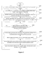
- Figure 1 shows a schematic flowchart of a method for monitoring and suppressing a resonance according to an embodiment of the present disclosure, and the method may be applied to a gird-connected generation system. According to the embodiment, the method may include step S110 to step S150.
- step S110 a current sample voltage of a preset sample point of the grid-connected generation system is monitored.
- the grid-connected generation system generally includes multiple inverters.
- Each of the multiple inverters includes one LCL filter, has a communication receiving RX function, and is connected to one step-up transformer via the LCL filter.
- a Point of Common Coupling (PPC point) at a high voltage side of all of the step-up transformers may be defined as the preset sample point, which is not limited herein.
- the current sample voltage may be acquired from a voltage transformer at the high voltage side of the grid-connected generation system via a sample conditioning circuit, which is referred to as U x .
- the current sample voltage may be a voltage of any one of A/B/C phases or AB/BC/CA phases of a three-phase grid.
- the current sample voltage is a line voltage.
- voltage sampling may be performed by sharing a voltage with a Luna Excursion Module (LEM) sensor or resistor; and then the collected voltage is filtered, amplified or reduced, and an output level of the collected voltage is processed via the conditioning circuit in the sample conditioning circuit, to obtain the current sample voltage.
- LEM Luna Excursion Module
- step S120 amplitudes of harmonics of the current sample voltage are acquired using a preset algorithm.
- the preset algorithm may include a Fast Fourier Transform (FFT) algorithm.
- FFT Fast Fourier Transform
- U x (n) indicates a discrete signal of the current sample voltage
- x(k) indicates a frequency domain value corresponding to a k-th harmonic of the current sample voltage after an FFT transformation is performed on the current sample voltage
- N indicates the total number of sample points
- ⁇ indicates a summation operation
- W N kn indicates a weight for the FFT algorithm and is a well-known calculation factor in an FFT standard butterfly algorithm, which is not described
- step S130 it is verified whether a resonance occurs in the grid-connected generation system based on the acquired amplitudes of the harmonics; in a case that the resonance occurs in the grid-connected generation system, the method proceeds to step S140; otherwise, the method returns to step S110.
- the operational reliability and stability of the grid-connected generation system is influenced.
- the grid-connected generation system can be monitored in a real time manner, and the resonance is processed immediately once the resonance occurs, thereby ensuring a reliable and stable operation of the grid-connected generation system.
- a resonance frequency f r of the gird-connected generation system should be less than f s /2 according to a system design requirement, hence, a maximum allowable resonance frequency f max of the grid-connected generation system may be set to be f s /2.
- the resonance frequency of the grid-connected generation system generally is greater than 1KHz in the system design, and a minimum allowable resonance frequency f min of the grid-connected generation system may be set to be 1KHz in the embodiment. It should be noted that, a range of a preset allowable resonance frequency band of the gird-connected generation system is not limited to [1KHz, f s /2].
- the valid values of the amplitudes of the harmonics within the preset resonance frequency band are acquired, it may be verified whether a resonance occurs in the grid-connected generation system currently by determining whether the valid values of the amplitudes of the harmonics are not less than a preset harmonic threshold. In a case that the valid values of the amplitudes of the harmonics are not less than the preset harmonic threshold, it is determined that the resonance occurs in the grid-connected generation system currently and the resonance is needed to be processed in an appropriate suppressing way; in a case that the valid values of the amplitudes of the harmonics are less than the preset harmonic threshold, the method may return to step S110 and it is monitored whether a resonance occurs in the grid-connected generation system.
- the preset harmonic threshold may be an allowable harmonic amplitude of an internal unit of the inverter in the grid-connected generation system, which is referred to as U rmin , and the preset harmonic threshold may be determined based on a model number of the grid-connected inverter and grid parameters, which is not limited in the present disclosure.
- the calculated valid values U r of the amplitudes of the harmonics are compared with the preset harmonic threshold U rmin ; in a case that U r ⁇ U rmin , it is determined that the resonance occurs in the grid-connected generation system; in a case that U r ⁇ U rmin , it is determined that the resonance does not occur in the grid-connected generation system, and the method returns to step S110.
- prompting information may be output to notify a user.
- the prompting information may be a beep sound, voice information or the like, which is not limited in the present disclosure.
- step S140 current corrections of the parameters of the inverters in the grid-connected generation system are acquired according to a preset rule.
- the current corrections may be calculated as follows.
- differences between the valid values U r of the amplitudes of the harmonics and the preset harmonic threshold U rmin may be calculated to obtain input errors U e which equal the difference of U rmin minus U r ; then the input errors are adjusted in proportion or a proportion-integral to obtain current output controls U 0 ; and amplitudes of the output controls are clipped to obtain the current corrections of the parameters of the inverters in the grid-connected generation system.
- K ⁇ is a proportional control coefficient, which may be determined based on parameters for ensuring a stable operation of the grid-connected generation system and a power grid, and is not limited in the present disclosure.
- ⁇ U out indicates current corrections output after the amplitudes are clipped.
- -U omax indicates a maximum allowable output value, to avoid the overshooting of the parameters of the inverters due to a great instantaneous change of the current corrections ⁇ U out and the damage on the stability of the system.
- step S150 the parameters of the inverters are adjusted using the current corrections and a selected resonance suppressing algorithm until the resonance disappears in the grid- connected generation system.
- the current corrections may be transmitted to the inverters through a communication bus respectively, the parameters of the inverters are adjusted with the current corrections and resonance points of the inverters are changed, and the valid values of the amplitudes of the harmonics of the monitored current sample voltage are less than the preset harmonic threshold. Hence, the resonance disappears in the grid-connected generation system.
- the communication bus may be an RS485 bus or a Controller Area Network (CAN) bus, which is not limited in the present disclosure.
- CAN Controller Area Network
- any inverter resonance suppressing method may be used according the characteristics of the inverters, such as an active damping method and an inactive damping method, which is not limited in the present disclosure.
- the current sample voltage of the preset sample point of the grid-connected generation system is monitored in a real time manner; the amplitudes of the harmonics of the current sample voltage are acquired using the preset algorithm; it is verified whether the resonance occurs in the grid-connected generation system currently based on the acquired amplitudes of the harmonics; in a case that the resonance occurs in the grid-connected generation system, the current corrections of the parameters of the inverters in the grid-connected generation system are acquired according to a preset rule and the parameters of the inverters are adjusted using the current corrections and a selected resonance suppressing algorithm until the resonance disappears in the grid-connected generation system. It follows that, according to the present disclosure, the resonance point of the grid-connected generation system is adjusted dynamically to suppress the resonance occurred in the grid-connected generation system, thereby ensuring a reliable and stable operation of the grid-connected generation system.
- Figure 2 shows a schematic flowchart of a method for monitoring and suppressing resonance according to a preferred embodiment of the present disclosure, which may be applied to a grid-connected generation system.
- the method may include step S201 to step S209.
- step S201 a current sample voltage of a preset sample point of the grid-connected generation system is monitored.
- the grid-connected generation system includes multiple inverters.
- the preset sample point may be a point of common coupling at a high voltage side of step-up transformers of the system.
- the current sample voltage is a line voltage.
- step S202 frequency domain values corresponding to harmonics of the current sample voltage are calculated using an FFT algorithm.
- An expression of the FFT algorithm may be the above-described formula (1), which is not described.
- step S203 amplitudes of the harmonics are calculated using the frequency domain values and a preset harmonic extracting formula.
- the amplitudes of the harmonics may be calculated using the above-described formula (2), and a specific process may be referred to the corresponding part of the above-described embodiment, which is not described.
- step S204 valid values of the amplitudes of the harmonics within the preset resonance frequency band are calculated using the amplitudes of the harmonics and a preset valid value calculation formula.
- the preset valid value calculation formula may be the above-described formula (3), and a specific process for calculating the valid values of the amplitudes of the harmonics may be referred to the corresponding part of the above embodiment, which is not described.
- step S205 it is verified whether the valid values of the amplitudes of the harmonics are not less than a preset harmonic threshold; in a case that the valid values are not less than the preset harmonic threshold, the method proceeds to step S206; otherwise, the method returns to step S201.
- the preset harmonic threshold may be an allowable harmonic amplitude of an internal unit of an inverter in the grid-connected generation system, which is referred to as U rmin .
- U rmin an allowable harmonic amplitude of an internal unit of an inverter in the grid-connected generation system
- prompting information may be output to prompt a user.
- the way of outputting the prompting information is not limited in the embodiment, and any way obtained by those skilled in the art without any creative work falls within the scope of protection of the present disclosure.
- step S206 differences between the valid values of the amplitudes of the harmonics and the preset harmonic threshold are calculated to obtain input errors.
- the input error U e equals the difference of U rmin minus U r .
- step S207 the input errors are adjusted in proportion to obtain current output controls.
- the input errors may be adjusted in a proportion-integral control instead of the proportion control.
- K ⁇ is a proportion control coefficient, which may be determined based on parameters for ensuring a stable operation of the grid-connected generation system and a power grid, and is not limited in the present disclosure.
- step S208 amplitudes of the current output controls are clipped to obtain current corrections of the parameters of the inverters in the grid-connected generation system.
- the amplitudes of the current output controls may be clipped using the above-described formula (4), and a specific process may be referred to the description of the corresponding part of the above embodiment, which is not described in the embodiment.
- step S209 the parameters of the inverters are adjusted using the current corrections and a preset resonance suppressing algorithm, and the method returns to step S201.
- the system monitors a current sample voltage of the preset sample point of the adjusted grid-connected generation system; the parameters of the inverter are not adjusted in a case that it is determined that the valid values of the amplitudes of the harmonics of the current sample voltage are less than the preset harmonic threshold.
- any one of the following ways may be used to adjust the parameter, and the adjustment way is not limited to the following ways. Different parameter adjusting ways or the same parameter adjusting way may be used for different inverters.
- an automatic control theory is used.
- the resonance point of the system changes as the proportion control parameter k p changes; the inverters in the grid-connected generation system can identify the resonance frequency band intelligently, and change their own resonance points using the received current corrections, thereby avoiding the resonance in the system and suppressing the resonance.
- Active damping coefficients of the inverters are adjusted using a pre-stored active damping algorithm and the current corrections.
- the pre-stored active damping algorithm may be called, and active damping coefficients K r of the inverters are adjusted using the received current corrections.
- k r indicates an active damping coefficient
- ⁇ U out indicates the obtained current correction
- K rmin and K rmax indicate a minimum adjustment value and a maximum adjustment value of the active damping system of the inverter respectively.
- the damping coefficient k r should not be too great, to prevent the noise from being amplified.
- an inactive damping resistor may be controlled to be connected to a control circuit of the inverter, thereby suppressing the resonance.
- the connected inactive damping resistor may be disconnected to strike a balance among the system efficiency, the stability and the resonance suppressing.
- a priority may be preset for the above-described three adjustment ways.
- corresponding resonance suppressing algorithms may be called in an order of the first way, the second way and the third way, which is not limited herein.
- a power failure protection may be performed on the adjusted parameters of the inverters.
- the inverters of the grid-connected generation system may be controlled to stop operating, to prevent an internal unit of the inverter from being damaged due to the resonance.
- the current sample voltage of the preset sample point of the grid-connected generation system is monitored in a real time manner; the amplitudes of the harmonics of the current sample voltage are acquired using the preset algorithm; it is verified whether the resonance occurs in the grid-connected generation system currently based on the acquired amplitudes of the harmonics; in a case that the resonance occurs in the grid-connected generation system, the current corrections of the parameters of the inverters in the grid-connected generation system are obtained according to a preset rule; and the parameters of the inverters are adjusted using the current corrections and a selected resonance suppressing algorithm, until the resonance disappears in the grid-connected generation system.
- the resonance point of the grid-connected generation system is adjusted dynamically to suppress the resonance occurred in the grid-connected generation system, thereby ensuring a reliable and stable operation of the grid-connected generation system.
- Figure 3 shows a schematic structural diagram of a device for monitoring and suppressing a resonance according to an embodiment of the present disclosure, and the device may be applied to a grid-connected generation system.
- the device may include a sample conditioning circuit 310, a controller 320, a communication bus 330 and an adjusting module 340.
- the sample conditioning circuit 310 is connected to a preset sample point of the grid-connected generation system and configured to monitor a current sample voltage of the preset sample point.
- the grid-connected generation system may include multiple inverters. Each of the multiple inverters is connected to one step-up transformer via one LCL filter and has a communication receiving RX function.
- the present sample point of the sample conditioning circuit 310 may be defined as a point of common coupling (PCC point) at a high voltage side of all of the step-up transformers.
- an alternate current signal at the high voltage side may be collected via a line voltage transformer in a high voltage distributing box, hence, an input terminal of the sample conditioning circuit 310 may be connected to the line voltage transformer, and a sample signal, i.e., a line voltage output from the line voltage transformer is detected in a real time manner by sharing a voltage with an LEM sensor or resistor.
- the sample signal is filtered, amplified or reduced to obtain the current sample voltage.
- the controller 320 is connected to the sample conditioning circuit 310 and configured to acquire amplitudes of harmonics of the current sample voltage using a preset algorithm; verify whether a resonance occurs in the grid-connected generation system based on the acquired amplitudes of the harmonics; and obtain current corrections of parameters of the inverters in the grid-connected generation system according to a preset rule in a case that the resonance occurs in the grid-connected generation system.
- controller 320 may be referred to the description of the corresponding part of the above method embodiment, which is not described in the embodiment.
- the controller 320 includes an analog-digital conversion circuit configured to perform analog-digital conversion on the current sample voltage output from the sample conditioning circuit 310 to facilitate later processing.
- the communication bus 330 is connected to the controller 320 and the inverters (n inverters, namely an inverter #1 to an inverter #n as shown in Figure 3 , which is not limited) in the grid-connected generation system and configured to transmit respectively the current corrections acquired by the controller 320 to the inverters in the grid-connected generation system.
- the inverters n inverters, namely an inverter #1 to an inverter #n as shown in Figure 3 , which is not limited
- the communication bus 330 may be an RS485 bus or a CAN bus, which is not limited herein.
- the adjusting module 340 (not shown in Figure 3 ) is connected to the controller 320 and the inverters and configured to adjust the parameters of the inverters using the current corrections and a preset resonance suppressing algorithm, until the resonance disappears in the grid-connected generation system.
- the specific adjusting process performed by the adjusting module 340 on the parameters of the inverters may be referred to the description of the corresponding part of the above method embodiment, which is not described in the embodiment.
- the device may further include an alarming device connected to the controller 320, and the alarming device is configured to output prompting information in a case that the controller 320 determines that a resonance occurs in the grid-connected generation system.
- the alarming device may be a buzzer, a voice module or the like, which is not limited in the present disclosure.
- the current sample voltage of the preset sample point of the grid-connected generation system is monitored in a real time manner; the amplitudes of the harmonics of the current sample voltage are acquired using the preset algorithm; it is verified whether the resonance occurs in the grid-connected generation system currently based on the acquired amplitudes of the harmonics; in a case that the resonance occurs in the grid-connected generation system, the current corrections of the parameters of the inverters in the grid-connected generation system are acquired according to a preset rule and the parameters of the inverters are adjusted using the current corrections and a selected resonance suppressing algorithm, until the resonance disappears in the grid-connected generation system. It follows that, according to the present disclosure, the resonance point of the grid-connected generation system is adjusted dynamically to suppress the resonance occurred in the grid-connected generation system, thereby ensuring a reliable and stable operation of the grid-connected generation system.
- the controller 320 may include a frequency domain calculation module 321 (not shown in Figure 3 ), an amplitude calculation module 322 (not shown in Figure 3 ), a valid value calculation module 323, a verifying module 324 (not shown in Figure 3 ), an error calculation module 325, a control acquiring module 326 and an amplitude clipping module 327.
- the frequency domain calculation module 321 and the amplitude calculation module 322 are arranged in the FFT block shown in Figure 3 .
- the verifying module 324 is configured to verify whether the valid values of the amplitudes of the harmonics are not less than a preset harmonic threshold.
- the preset harmonic threshold may be an allowable harmonic amplitude of an internal unit of an inverter in the grid-connected generation system, which is referred to as U min , and the preset harmonic threshold may be determined based on a specific model number of the grid-connected inverter and grid parameters, which is not limited in the present disclosure.
- a closed loop i.e., a resonance amplitude control loop
- a resonance amplitude control loop is formed in the structure of the device according to the present disclosure, thereby adjusting the resonance in the grid-connected generation system dynamically, and ensuring a reliable and stable operation of the grid-connected generation system.
- the error calculation module 325 is configured to calculate differences between the valid values of the amplitudes of the harmonics and the preset harmonic threshold to obtain input errors.
- the input error equals the difference of the preset harmonic threshold minus the valid value of the amplitude of the harmonic, which is not limited.
- the control acquiring module 326 is configured to adjust the input errors in proportion or proportion-integral to obtain current output controls.
- the amplitude clipping module 327 is configured to clip amplitudes of the current output controls to obtain current corrections of the parameters of the inverters in the grid-connected generation system.
- the amplitudes of the current output controls may be clipped using the above formula (4), a specific process may be referred to the description of the corresponding part of the above method embodiment, which is not described in the embodiment.
- the ways for clipping the amplitudes are not limited to the above-described ways, any way obtained by those skilled in the art without any creative work falls within the scope of protection of the present disclosure.
- the adjusting module 340 may include a first adjusting unit 341, a second adjusting unit 342 and a third adjusting unit 343, as shown in Figure 4 .
- the second adjusting unit 342 is configured to adjust active damping coefficients of the inverters using a preset active damping algorithm and the current corrections.
- the active damping adjustment may be performed using the above formula (6), and a specific process may be referred to the description of the corresponding part of the above method embodiment, which is not described in the embodiment.
- the third adjusting unit 343 is configured to transmit respectively the current corrections to the inverters to control the inactive damping resistor to be connected to a respective one of the inverters.
- the inactive damping resistor may be disconnected in a case that it is verified that the resonance does not occur in the grid-connected generation system, that is, the valid values of the amplitudes of the harmonics are less than the preset harmonic threshold.
- the first adjusting unit, the second adjusting unit and the third adjusting unit may be triggered according to a preset priority, and a specific order of priority is not limited in the present disclosure.
- the device may further include a timer 350 (not shown in Figure 4 ) and a storage module 360.
- the timer 350 is configured to track the correction effect of the parameters of the inverters.
- the timer is started once the parameters of the inverters are adjusted using the first adjusting unit, the second adjusting unit and/or the third adjusting unit; and it is determined whether the valid values U r of the corrected amplitudes of the harmonics of the current sample voltage changes in a real time manner within a predetermined period of time.
- the error calculation module 325 calculates the received valid values of the amplitudes of the harmonics to obtain input errors and transmits the input errors to the control acquiring module 326.
- the input errors are adjusted in a proportion control to obtain current output controls U 0 , and then amplitudes of the current output controls U 0 are clipped by the amplitude clipping module 327 to obtain current corrections ⁇ U out .
- the adjusting module 340 may be connected to the first adjusting unit 341, the second adjusting unit 342 and the third adjusting unit 343 sequentially according to a preset priority S m , thereby adjusting the parameters of the grid-connected inverter.
- the storage module 360 is configured to perform a power failure protection on the corrected parameters of the inverters in a case that the valid values of the amplitudes of the harmonics are reduced gradually and are less than the preset harmonic threshold U rmin , and the related parameters are directly called from the storage module once the grid-connected generation system is powered, thereby preventing a resonance from occurring once more.
- the storage module 360 may be a non-volatile ferroelectric RAM (FRAM), i.e., a random access memory, specific functions and features thereof may be referred to the conventional FRAM, which is not described in the embodiment.
- FRAM non-volatile ferroelectric RAM
- the storage module 360 is triggered to perform a power failure protection on the corrected parameters of the grid-connected inverters.
- the U r is not reduced or is still greater than U rmax after the preset period of time, that is to say, the resonance cannot be suppressed by correcting the parameters and the resonance becomes increasingly severe.
- the protection control module 370 may be directly triggered to transmit a protection signal to the inverters to control the inverters to stop operating.
- the current sample voltage of the preset sample point of the grid-connected generation system is monitored in a real time manner; the amplitudes of the harmonics of the current sample voltage are acquired using the preset algorithm; it is verified whether the resonance occurs in the grid-connected generation system currently based on the acquired amplitudes of e the harmonics; in a case that the resonance occurs in the grid-connected generation system, the current corrections of the parameters of the inverters in the grid-connected generation system are acquired according to a preset rule; and the parameters of the inverters are adjusted using the current corrections and a selected resonance suppressing algorithm until the resonance disappears in the grid-connected generation system. It follows that, according to the present disclosure, the resonance point of the grid-connected generation system is adjusted dynamically to suppress the resonance occurred in the grid-connected generation system, thereby ensuring a reliable and stable operation of the grid-connected generation system.
Landscapes
- Engineering & Computer Science (AREA)
- Power Engineering (AREA)
- Physics & Mathematics (AREA)
- Nonlinear Science (AREA)
- Mathematical Physics (AREA)
- General Physics & Mathematics (AREA)
- Inverter Devices (AREA)
- Supply And Distribution Of Alternating Current (AREA)
- Remote Monitoring And Control Of Power-Distribution Networks (AREA)
Abstract
Description
- The present disclosure relates to the application field of a grid-connected generation system, and in particular, to a method and device for monitoring and suppressing a resonance.
- In the development process of new energy, as grid-connected generation for the new energy such as a solar battery, a wind power and a fuel cell becomes increasingly popular, the technology of grid-connected inverter generation becomes a focus for study.
- It is found by the applicant that, in a practical application, as the number of inverters in a grid-connected generation system increases, generally a resonance occurs in the grid-connected generation system due to the unreasonable design of a control circuit and mutual influence among impedances of control devices, thereby influencing a safe and reliable operation of the grid-connected generation system.
- Therefore, in order to suppress the resonance occurred in the grid-connected generation system, the resonance is generally suppressed using an LCL filter included in the inverter in the conventional technology, for example, with a common active damping suppressing method in the field. However, in the conventional active damping resonance suppressing method, a sample sensor is added, and the feasibility and stability are poor; particularly for a large-scale grid-connected generation system, the generated resonance in the system is generally complicated, the resonance cannot be suppressed using a specific resonance suppressing algorithm, the resonance even increases due to unsuitable control, and thus the grid-connected generation system cannot be ensured to operate reliably and stably.
- In view of the above, a method and device for monitoring and suppressing a resonance are provided, to solve a technical problem that a grid-connected generation system cannot be ensured to operate reliably and stably with the conventional resonance suppressing method.
- In order to achieve the above object, technical solutions are provided according to the present disclosure.
- A method for monitoring and suppressing a resonance applied to a grid-connected generation system is provided, and the method includes:
- monitoring a current sample voltage of a preset sample point of the grid-connected generation system;
- acquiring amplitudes of harmonics of the current sample voltage using a preset algorithm;
- verifying whether a resonance occurs in the grid-connected generation system based on the acquired amplitudes of the harmonics; and
- in a case that the resonance occurs in the grid-connected generation system, acquiring current corrections of parameters of inverters in the grid-connected generation system according to a preset rule, and adjusting the parameters of the inverters using the current corrections and a selected resonance suppressing algorithm until the resonance disappears in the grid-connected generation system.
- Preferably, the acquiring amplitudes of harmonics of the current sample voltage using a preset algorithm may include:
- calculating frequency domain values corresponding to the harmonics of the current sample voltage using an FFT algorithm formula, and the FFT algorithm formula is:

- calculating the amplitudes of the harmonics using the frequency domain values and a preset harmonic extracting formula, and the preset harmonic extracting formula is:

- Preferably, the verifying whether a resonance occurs in the grid-connected generation system based on the acquired amplitudes of the harmonics may include:
- calculating valid values of amplitudes of the harmonics within a preset resonance frequency band using the amplitudes of the harmonics and a preset valid value calculation formula, and
- the preset valid value calculation formula is:

- verifying whether the valid values of the amplitudes of the harmonics are not less than a preset harmonic threshold,
- where it is determined that the resonance occurs in the grid-connected generation system in a case that the valid values of the amplitudes of the harmonics are not less than the preset harmonic threshold.
- Preferably, the acquiring current corrections of parameters of inverters in the grid-connected generation system according to a preset rule may include:
- calculating differences between the valid values of the amplitudes of the harmonics and the preset harmonic threshold to obtain input errors;
- adjusting the input errors in proportion or proportion-integral to obtain current output controls; and
- clipping amplitudes of the current output controls to obtain the current corrections of the parameters of the inverters in the grid-connected generation system.
- Preferably, the adjusting the parameters of the inverters using the current corrections and a preset resonance suppressing algorithm may include:
- adjusting bandwidths of the inverters using the current corrections and a preset adjustment formula, and the preset adjustment formula is:

- where Kp indicates a proportion control parameter, ΔUout indicates the current corrections and Kpmin indicates minimum allowable adjustment values of the bandwidths of the inverters; and/or
- adjusting active damping coefficients of the inverters using a pre-stored active damping algorithm and the current corrections; and/or
- transmitting respectively the current corrections to the inverters to control an inactive damping resistor to be connected to a respective one of the inverters.
- Preferably, after the adjusting the parameters of the inverters using the current corrections and a preset resonance suppressing algorithm, the method may further include:
- controlling the inverters of the grid-connected generation system to stop operating in a case that the resonance does not disappear in the grid-connected generation system after a preset period of time.
- Preferably, in a case that the resonance disappears in the grid-connected generation system, the method may further include:
- performing a power failure protection on the adjusted parameters of the inverters.
- A device for monitoring and suppressing a resonance applied to a grid-connection generation system is provided, and the device includes:
- a sample conditioning circuit connected to a preset sample point of the grid-connected generation system and configured to monitor a current sample voltage of the preset sample point;
- a controller connected to the sample conditioning circuit and configured to acquire amplitudes of harmonics of the current sample voltage using a preset algorithm, verify whether a resonance occurs in the grid-connected generation system based on the acquired amplitudes of the harmonics, and acquire current corrections of parameters of inverters in the grid-connected generation system according to a preset rule in a case that the resonance occurs in the grid-connected generation system;
- a communication bus connected to the controller and the inverters in the grid-connected generation system and configured to transmit the current corrections acquired by the controller to the inverters respectively; and
- an adjusting module connected to the controller and the inverters and configured to adjust the parameters of the inverters using the current corrections and a preset resonance suppressing algorithm until the resonance disappears in the grid-connected generation system.
- Preferably, the controller may include:
- a frequency domain calculation module configured to calculate frequency domain values corresponding to the current sample voltage using an FFT algorithm formula, and the FFT algorithm formula is:

- an amplitude calculation module configured to calculate the amplitude of the harmonics using the frequency domain values and a preset harmonic extracting formula, and the preset harmonic extracting formula is:

- a valid value calculation module configured to calculate valid values of the amplitudes of the harmonics within a preset resonance frequency band using the amplitudes of the harmonics and a preset valid value calculation formula, and the preset valid value calculation formula is:

- a verifying module configured to verify whether the valid values of the amplitudes of the harmonics are not less than a preset harmonic threshold;
- an error calculation module configured to calculate differences between the valid values of the amplitudes of the harmonics and the preset harmonic threshold to obtain input errors;
- a control acquiring module configured to adjust the input errors in proportion or proportion-integral to obtain current output controls; and
- an amplitude clipping module configured to clip amplitudes of the current output controls to obtain the current corrections of the parameters of the inverters in the grid-connected generation system.
- Preferably, the adjusting module may include:
- a first adjusting unit configured to adjust bandwidths of the inverters using the current corrections and a preset adjustment formula, and the preset adjustment formula is:

- a second adjusting unit configured to adjust active damping coefficients of the inverters using a preset active damping algorithm and the current corrections; and
- a third adjusting unit configured to transmit respectively the current corrections to the inverters to control an inactive damping resistor to be connected to a respective one of the inverters.
- It follows that, as compared with the conventional technology, a method and device for monitoring and suppressing a resonance applied to a grid-connected generation system are provided according to the present disclosure, the current sample voltage of the preset sample point of the grid-connected generation system is monitored in a real time manner; the amplitudes of the harmonics of the current sample voltage are acquired using the preset algorithm; it is verified whether the resonance occurs in the grid-connected generation system currently based on the acquired amplitudes of the harmonics; in a case that the resonance occurs in the grid-connected generation system, the current corrections of the parameters of the inverters in the grid-connected generation system are acquired according to the preset rule; and the parameters of the inverters are adjusted using the current corrections and a selected resonance suppressing algorithm until the resonance disappears in the grid-connected generation system. Therefore, according to the present disclosure, the resonance point of the grid-connected generation system is adjusted dynamically to suppress the resonance occurred in the grid-connected generation system, thereby ensuring a reliable and stable operation of the grid-connected generation system.
- In order to illustrate technical solutions in embodiments of the present disclosure or the conventional technology more clearly, hereinafter drawings to be used in the description of the embodiments or the conventional technology are introduced simply. Apparently, the drawings described below are only for the embodiments of present disclosure. For those skilled in the art, other drawings may be obtained based on the provided drawings without any creative work.
-
Figure 1 is a schematic flowchart of a method for monitoring and suppressing a resonance according to an embodiment of the present disclosure; -
Figure 2 is a schematic flowchart of a method for monitoring and suppressing a resonance according to a preferred embodiment of the present disclosure; -
Figure 3 is a schematic structural diagram of a device for monitoring and suppressing a resonance according to an embodiment of the present disclosure; and -
Figure 4 is schematic structural diagram of a part of a device for monitoring and suppressing a resonance according to an embodiment of the present disclosure. - Hereinafter technical solutions of embodiments of the present disclosure are described clearly and completely in conjunction with the drawings of the embodiments of the present disclosure. Apparently, the described embodiments are only some rather than all of the embodiments of the present disclosure. Any other embodiments obtained based on the embodiments of the present disclosure by those skilled in the art without any creative work fall within the scope of protection of the present disclosure.
- A method and device for monitoring and suppressing a resonance applied to a grid-connected generation system are provided according to the present disclosure. A current sample voltage of a preset sample point of the grid-connected generation system is monitored in a real time manner; amplitudes of harmonics of the current sample voltage are acquired using a preset algorithm; it is verified whether a resonance occurs in the grid-connected generation system currently based on the acquired amplitudes of the harmonics; in a case that the resonance occurs in the grid-connected generation system, current corrections of parameters of inverters in the grid-connected generation system are acquired according to a preset rule and the parameters of the inverters are adjusted using the current corrections and a selected resonance suppressing algorithm until the resonance disappears in the grid-connected generation system. It follows that, according to the present disclosure, a resonance point of the grid-connected generation system is adjusted dynamically to suppress the resonance occurred in the grid-connected generation system, thereby ensuring a reliable and stable operation of the grid-connected generation system.
-
Figure 1 shows a schematic flowchart of a method for monitoring and suppressing a resonance according to an embodiment of the present disclosure, and the method may be applied to a gird-connected generation system. According to the embodiment, the method may include step S110 to step S150. - In step S110, a current sample voltage of a preset sample point of the grid-connected generation system is monitored.
- In a practical application, the grid-connected generation system generally includes multiple inverters. Each of the multiple inverters includes one LCL filter, has a communication receiving RX function, and is connected to one step-up transformer via the LCL filter. Hence, in the embodiment, a Point of Common Coupling (PPC point) at a high voltage side of all of the step-up transformers may be defined as the preset sample point, which is not limited herein.
- The current sample voltage may be acquired from a voltage transformer at the high voltage side of the grid-connected generation system via a sample conditioning circuit, which is referred to as Ux. In the embodiment, the current sample voltage may be a voltage of any one of A/B/C phases or AB/BC/CA phases of a three-phase grid. Generally, the current sample voltage is a line voltage. Specifically, voltage sampling may be performed by sharing a voltage with a Luna Excursion Module (LEM) sensor or resistor; and then the collected voltage is filtered, amplified or reduced, and an output level of the collected voltage is processed via the conditioning circuit in the sample conditioning circuit, to obtain the current sample voltage.
- In step S120, amplitudes of harmonics of the current sample voltage are acquired using a preset algorithm.
- The preset algorithm may include a Fast Fourier Transform (FFT) algorithm. Hence, in the embodiment, firstly frequency domain values corresponding to the harmonics of the current sample voltage may be calculated using the FFT algorithm formula, and the FFT algorithm formula may be:

here Ux(n) indicates a discrete signal of the current sample voltage; x(k) indicates a frequency domain value corresponding to a k-th harmonic of the current sample voltage after an FFT transformation is performed on the current sample voltage; N indicates the total number of sample points; ∑ indicates a summation operation; and WN kn indicates a weight for the FFT algorithm and is a well-known calculation factor in an FFT standard butterfly algorithm, which is not described in details in the present disclosure. - Then, the amplitudes of the harmonics are calculated using the acquired frequency domain values and a preset harmonic extracting formula, and the preset harmonic extracting formula is:

where Uamp(k) indicates an amplitude of a k-th harmonic, and X(2k) and X(2K+1) indicate frequency domain values of a 2k-th harmonic and a (2k+1)-th harmonic respectively. - In step S130, it is verified whether a resonance occurs in the grid-connected generation system based on the acquired amplitudes of the harmonics; in a case that the resonance occurs in the grid-connected generation system, the method proceeds to step S140; otherwise, the method returns to step S110.
- In a practical application, in a case that the resonance occurs in the grid-connected generation system, the operational reliability and stability of the grid-connected generation system is influenced. Hence, in the embodiment, the grid-connected generation system can be monitored in a real time manner, and the resonance is processed immediately once the resonance occurs, thereby ensuring a reliable and stable operation of the grid-connected generation system.
- Optionally, in the embodiment, assumed that a switching frequency of the grid-connected generation system is fs, a resonance frequency fr of the gird-connected generation system should be less than fs/2 according to a system design requirement, hence, a maximum allowable resonance frequency fmax of the grid-connected generation system may be set to be fs/2. Once the resonance frequency is greater than fs/2, the resonance suppressing algorithm is disabled, that is to say, the resonance cannot be suppressed, and the inverters of the grid-connected generation system may be controlled directly to stop operating.
- In addition, in order to ensure a performance of a filter in the grid-connected generation system and improve a system response characteristic, a bandwidth of the system should not be too small. Therefore, the resonance frequency of the grid-connected generation system generally is greater than 1KHz in the system design, and a minimum allowable resonance frequency fmin of the grid-connected generation system may be set to be 1KHz in the embodiment. It should be noted that, a range of a preset allowable resonance frequency band of the gird-connected generation system is not limited to [1KHz, fs/2].
- According to the analysis above, in the embodiment, the valid values of amplitudes of the harmonics within the preset harmonic frequency band may be calculated using the amplitudes of the harmonics and a preset valid value calculation formula, and the preset valid value calculation formula is:

where Ur indicates the valid values of the amplitudes of the harmonics within the preset resonance frequency band [fmin, fmax], N1 indicates the total number of resonances occurred within the preset resonance frequency band, M1 indicates the number of resonances corresponding to a minimum allowable resonance frequency fmin, M2 indicates the number of resonances corresponding to a maximum allowable resonance frequency fmax, and Uamp(k) indicates the amplitude of the k-th harmonic. - After the valid values of the amplitudes of the harmonics within the preset resonance frequency band are acquired, it may be verified whether a resonance occurs in the grid-connected generation system currently by determining whether the valid values of the amplitudes of the harmonics are not less than a preset harmonic threshold. In a case that the valid values of the amplitudes of the harmonics are not less than the preset harmonic threshold, it is determined that the resonance occurs in the grid-connected generation system currently and the resonance is needed to be processed in an appropriate suppressing way; in a case that the valid values of the amplitudes of the harmonics are less than the preset harmonic threshold, the method may return to step S110 and it is monitored whether a resonance occurs in the grid-connected generation system.
- The preset harmonic threshold may be an allowable harmonic amplitude of an internal unit of the inverter in the grid-connected generation system, which is referred to as Urmin, and the preset harmonic threshold may be determined based on a model number of the grid-connected inverter and grid parameters, which is not limited in the present disclosure. Therefore, according to the analysis above, the calculated valid values Ur of the amplitudes of the harmonics are compared with the preset harmonic threshold Urmin; in a case that Ur≥Urmin, it is determined that the resonance occurs in the grid-connected generation system; in a case that Ur<Urmin, it is determined that the resonance does not occur in the grid-connected generation system, and the method returns to step S110.
- Optionally, in a case that it is determined that the resonance occurs in the grid-connected generation system, prompting information may be output to notify a user. The prompting information may be a beep sound, voice information or the like, which is not limited in the present disclosure.
- In step S140, current corrections of the parameters of the inverters in the grid-connected generation system are acquired according to a preset rule.
- In the embodiment, the current corrections may be calculated as follows.
- After the valid values Ur of the amplitudes of the harmonics are acquired, differences between the valid values Ur of the amplitudes of the harmonics and the preset harmonic threshold Urmin may be calculated to obtain input errors Ue which equal the difference of Urmin minus Ur; then the input errors are adjusted in proportion or a proportion-integral to obtain current output controls U0; and amplitudes of the output controls are clipped to obtain the current corrections of the parameters of the inverters in the grid-connected generation system.
- Taking the input errors being adjusted in proportion as an example, in a practical application of the embodiment, the input errors Ue are adjusted according to a formula Uo=KτUe= Kτ(Urmin-Ur) to obtain the current output controls Uo. Kτ is a proportional control coefficient, which may be determined based on parameters for ensuring a stable operation of the grid-connected generation system and a power grid, and is not limited in the present disclosure.
- Optionally, the amplitudes of the current output controls U0 may be clipped according to the following amplitude clipping formula, which may be expressed as:

- In the formula, ΔUout indicates current corrections output after the amplitudes are clipped. -Uomax indicates a maximum allowable output value, to avoid the overshooting of the parameters of the inverters due to a great instantaneous change of the current corrections ΔUout and the damage on the stability of the system.
- In step S150, the parameters of the inverters are adjusted using the current corrections and a selected resonance suppressing algorithm until the resonance disappears in the grid- connected generation system.
- Optionally, in a practical application, after the current corrections of the parameters of the inverters are acquired, the current corrections may be transmitted to the inverters through a communication bus respectively, the parameters of the inverters are adjusted with the current corrections and resonance points of the inverters are changed, and the valid values of the amplitudes of the harmonics of the monitored current sample voltage are less than the preset harmonic threshold. Hence, the resonance disappears in the grid-connected generation system.
- The communication bus may be an RS485 bus or a Controller Area Network (CAN) bus, which is not limited in the present disclosure.
- It should be noted that, in a case that the resonance is suppressed by the inverters using the current corrections, any inverter resonance suppressing method may be used according the characteristics of the inverters, such as an active damping method and an inactive damping method, which is not limited in the present disclosure.
- According to the analysis above, in the embodiment of the present disclosure, the current sample voltage of the preset sample point of the grid-connected generation system is monitored in a real time manner; the amplitudes of the harmonics of the current sample voltage are acquired using the preset algorithm; it is verified whether the resonance occurs in the grid-connected generation system currently based on the acquired amplitudes of the harmonics; in a case that the resonance occurs in the grid-connected generation system, the current corrections of the parameters of the inverters in the grid-connected generation system are acquired according to a preset rule and the parameters of the inverters are adjusted using the current corrections and a selected resonance suppressing algorithm until the resonance disappears in the grid-connected generation system. It follows that, according to the present disclosure, the resonance point of the grid-connected generation system is adjusted dynamically to suppress the resonance occurred in the grid-connected generation system, thereby ensuring a reliable and stable operation of the grid-connected generation system.
-
Figure 2 shows a schematic flowchart of a method for monitoring and suppressing resonance according to a preferred embodiment of the present disclosure, which may be applied to a grid-connected generation system. The method may include step S201 to step S209. - In step S201, a current sample voltage of a preset sample point of the grid-connected generation system is monitored.
- The grid-connected generation system includes multiple inverters. The preset sample point may be a point of common coupling at a high voltage side of step-up transformers of the system. Generally the current sample voltage is a line voltage.
- In step S202, frequency domain values corresponding to harmonics of the current sample voltage are calculated using an FFT algorithm.
- An expression of the FFT algorithm may be the above-described formula (1), which is not described.
- In step S203, amplitudes of the harmonics are calculated using the frequency domain values and a preset harmonic extracting formula.
- In the embodiment, the amplitudes of the harmonics may be calculated using the above-described formula (2), and a specific process may be referred to the corresponding part of the above-described embodiment, which is not described.
- In step S204, valid values of the amplitudes of the harmonics within the preset resonance frequency band are calculated using the amplitudes of the harmonics and a preset valid value calculation formula.
- The preset valid value calculation formula may be the above-described formula (3), and a specific process for calculating the valid values of the amplitudes of the harmonics may be referred to the corresponding part of the above embodiment, which is not described.
- In step S205, it is verified whether the valid values of the amplitudes of the harmonics are not less than a preset harmonic threshold; in a case that the valid values are not less than the preset harmonic threshold, the method proceeds to step S206; otherwise, the method returns to step S201.
- In the embodiment of the present disclosure, the preset harmonic threshold may be an allowable harmonic amplitude of an internal unit of an inverter in the grid-connected generation system, which is referred to as Urmin. In a case that the calculated amplitudes of the harmonics are greater than or equal to the preset harmonic threshold, it is indicated that the resonance occurs in the grid-connected generation system and the resonance is needed to be suppressed in a real time manner, thereby ensuring a reliable and stable operation of the grid-connected generation system.
- Preferably, in a case that it is determined the resonance occurs in the grid-connected generation system, prompting information may be output to prompt a user. The way of outputting the prompting information is not limited in the embodiment, and any way obtained by those skilled in the art without any creative work falls within the scope of protection of the present disclosure.
- In step S206, differences between the valid values of the amplitudes of the harmonics and the preset harmonic threshold are calculated to obtain input errors.
- According to the description of the corresponding part of the above embodiment, the input error Ue equals the difference of Urmin minus Ur.
- In step S207, the input errors are adjusted in proportion to obtain current output controls.
- It should be noted that, in the present disclosure, the input errors may be adjusted in a proportion-integral control instead of the proportion control. In the embodiment, taking the proportion control as an example, the input errors Ue may be adjusted according to a formula U0=KτUe= Kτ(Urmin-Ur) to obtain current output controls Uo.
- Kτ is a proportion control coefficient, which may be determined based on parameters for ensuring a stable operation of the grid-connected generation system and a power grid, and is not limited in the present disclosure.
- In step S208, amplitudes of the current output controls are clipped to obtain current corrections of the parameters of the inverters in the grid-connected generation system.
- In the embodiment, the amplitudes of the current output controls may be clipped using the above-described formula (4), and a specific process may be referred to the description of the corresponding part of the above embodiment, which is not described in the embodiment.
- In step S209, the parameters of the inverters are adjusted using the current corrections and a preset resonance suppressing algorithm, and the method returns to step S201.
- In a practical application, in a case that the parameters of the inverter are adjusted using the current corrections, the system monitors a current sample voltage of the preset sample point of the adjusted grid-connected generation system; the parameters of the inverter are not adjusted in a case that it is determined that the valid values of the amplitudes of the harmonics of the current sample voltage are less than the preset harmonic threshold.
- For any one of the inverters, any one of the following ways may be used to adjust the parameter, and the adjustment way is not limited to the following ways. Different parameter adjusting ways or the same parameter adjusting way may be used for different inverters.
- A bandwidth ΔωB of the inverter is adjusted using the received current correction ΔUout and a preset adjustment formula, and the preset adjustment formula may be expressed as:

where Kp indicates a proportion control parameter, and Kpmin indicates a minimum allowable adjustment value of the bandwidth of the inverter. - In the first way of the embodiment, an automatic control theory is used. The resonance point of the system changes as the proportion control parameter kp changes; the inverters in the grid-connected generation system can identify the resonance frequency band intelligently, and change their own resonance points using the received current corrections, thereby avoiding the resonance in the system and suppressing the resonance.
- Active damping coefficients of the inverters are adjusted using a pre-stored active damping algorithm and the current corrections.
- In a practical application of the embodiment, after the active damping suppressing resonance method is selected based on characteristics of the inverters, the pre-stored active damping algorithm may be called, and active damping coefficients Kr of the inverters are adjusted using the received current corrections. The adjustment may be performed based on the following formula.

- In the above-described formula (6), kr indicates an active damping coefficient, ΔUout indicates the obtained current correction, and Krmin and Krmax indicate a minimum adjustment value and a maximum adjustment value of the active damping system of the inverter respectively.
- In a practical application of the embodiment, since a differential operation is introduced in the active damping algorithm, the damping coefficient kr should not be too great, to prevent the noise from being amplified.
- According to an inactive damping principle, after the obtained current corrections are transmitted to the inverters respectively, an inactive damping resistor may be controlled to be connected to a control circuit of the inverter, thereby suppressing the resonance.
- Extra loss such as heat dissipation of the device is increased and the system efficiency is reduced since the inactive damping resistance is added. Hence, in a case that it is determined that the valid values of the amplitudes of the harmonics are less than the preset harmonic threshold, the connected inactive damping resistor may be disconnected to strike a balance among the system efficiency, the stability and the resonance suppressing.
- As another embodiment of the present disclosure, a priority may be preset for the above-described three adjustment ways. For example, corresponding resonance suppressing algorithms may be called in an order of the first way, the second way and the third way, which is not limited herein. Once the adjustment is completed in any one of the above-described ways, it is verified whether the valid value of the current harmonic amplitude is less than the preset harmonic threshold; in a case that the valid value is less than the preset harmonic threshold, the method returns to step S201; otherwise, the parameters of the inverters may be adjusted by calling a resonance suppressing algorithm with a next priority, until the resonance disappears in the grid-connected generation system.
- Optionally, according to the above-described embodiments, after the parameters of the inverters are adjusted such that the resonance disappears in the grid-connected generation system, a power failure protection may be performed on the adjusted parameters of the inverters. Practically, in a case that the parameters of the inverters are adjusted using the above ways and the resonance does not disappear in the grid-connected generation system after the preset period of time, that is, the valid values of the amplitudes of the harmonics are still not greater than the preset harmonic threshold, the inverters of the grid-connected generation system may be controlled to stop operating, to prevent an internal unit of the inverter from being damaged due to the resonance.
- According to the analysis above, in the embodiment of the present disclosure, the current sample voltage of the preset sample point of the grid-connected generation system is monitored in a real time manner; the amplitudes of the harmonics of the current sample voltage are acquired using the preset algorithm; it is verified whether the resonance occurs in the grid-connected generation system currently based on the acquired amplitudes of the harmonics; in a case that the resonance occurs in the grid-connected generation system, the current corrections of the parameters of the inverters in the grid-connected generation system are obtained according to a preset rule; and the parameters of the inverters are adjusted using the current corrections and a selected resonance suppressing algorithm, until the resonance disappears in the grid-connected generation system. It follows that, according to the present disclosure, the resonance point of the grid-connected generation system is adjusted dynamically to suppress the resonance occurred in the grid-connected generation system, thereby ensuring a reliable and stable operation of the grid-connected generation system.
-
Figure 3 shows a schematic structural diagram of a device for monitoring and suppressing a resonance according to an embodiment of the present disclosure, and the device may be applied to a grid-connected generation system. In the present embodiment, the device may include asample conditioning circuit 310, acontroller 320, acommunication bus 330 and an adjusting module 340. - The
sample conditioning circuit 310 is connected to a preset sample point of the grid-connected generation system and configured to monitor a current sample voltage of the preset sample point. - The grid-connected generation system may include multiple inverters. Each of the multiple inverters is connected to one step-up transformer via one LCL filter and has a communication receiving RX function. Hence, the present sample point of the
sample conditioning circuit 310 may be defined as a point of common coupling (PCC point) at a high voltage side of all of the step-up transformers. - In a practical application, generally an alternate current signal at the high voltage side may be collected via a line voltage transformer in a high voltage distributing box, hence, an input terminal of the
sample conditioning circuit 310 may be connected to the line voltage transformer, and a sample signal, i.e., a line voltage output from the line voltage transformer is detected in a real time manner by sharing a voltage with an LEM sensor or resistor. The sample signal is filtered, amplified or reduced to obtain the current sample voltage. - It should be noted that, according to the above description of the function of the
sample conditioning circuit 310, those skilled in the art may obtain a specific circuit structure of thesample conditioning circuit 310 in conjunction with the conventional technology, which is not described in the embodiment. - The
controller 320 is connected to thesample conditioning circuit 310 and configured to acquire amplitudes of harmonics of the current sample voltage using a preset algorithm; verify whether a resonance occurs in the grid-connected generation system based on the acquired amplitudes of the harmonics; and obtain current corrections of parameters of the inverters in the grid-connected generation system according to a preset rule in a case that the resonance occurs in the grid-connected generation system. - In the embodiment, the specific function of the
controller 320 may be referred to the description of the corresponding part of the above method embodiment, which is not described in the embodiment. - The
controller 320 includes an analog-digital conversion circuit configured to perform analog-digital conversion on the current sample voltage output from thesample conditioning circuit 310 to facilitate later processing. - The
communication bus 330 is connected to thecontroller 320 and the inverters (n inverters, namely aninverter # 1 to an inverter #n as shown inFigure 3 , which is not limited) in the grid-connected generation system and configured to transmit respectively the current corrections acquired by thecontroller 320 to the inverters in the grid-connected generation system. - The
communication bus 330 may be an RS485 bus or a CAN bus, which is not limited herein. - The adjusting module 340 (not shown in
Figure 3 ) is connected to thecontroller 320 and the inverters and configured to adjust the parameters of the inverters using the current corrections and a preset resonance suppressing algorithm, until the resonance disappears in the grid-connected generation system. - In the embodiment, the specific adjusting process performed by the adjusting module 340 on the parameters of the inverters may be referred to the description of the corresponding part of the above method embodiment, which is not described in the embodiment.
- Optionally, based on the above embodiment, the device may further include an alarming device connected to the
controller 320, and the alarming device is configured to output prompting information in a case that thecontroller 320 determines that a resonance occurs in the grid-connected generation system. The alarming device may be a buzzer, a voice module or the like, which is not limited in the present disclosure. - According to the analysis above, in the embodiment of the present disclosure, the current sample voltage of the preset sample point of the grid-connected generation system is monitored in a real time manner; the amplitudes of the harmonics of the current sample voltage are acquired using the preset algorithm; it is verified whether the resonance occurs in the grid-connected generation system currently based on the acquired amplitudes of the harmonics; in a case that the resonance occurs in the grid-connected generation system, the current corrections of the parameters of the inverters in the grid-connected generation system are acquired according to a preset rule and the parameters of the inverters are adjusted using the current corrections and a selected resonance suppressing algorithm, until the resonance disappears in the grid-connected generation system. It follows that, according to the present disclosure, the resonance point of the grid-connected generation system is adjusted dynamically to suppress the resonance occurred in the grid-connected generation system, thereby ensuring a reliable and stable operation of the grid-connected generation system.
- As another embodiment of the present disclosure, based on the above embodiments, the
controller 320 may include a frequency domain calculation module 321 (not shown inFigure 3 ), an amplitude calculation module 322 (not shown inFigure 3 ), a validvalue calculation module 323, a verifying module 324 (not shown inFigure 3 ), anerror calculation module 325, acontrol acquiring module 326 and anamplitude clipping module 327. - The frequency domain calculation module 321 is configured to calculate frequency domain values corresponding to the current sample voltage using an FFT algorithm formula, where the preset FFT algorithm formula may be :

where Ux(n) indicates a discrete signal of the current sample voltage, x(k) indicates a frequency domain value corresponding to a k-th harmonic of the current sample voltage after the FFT transformation is performed on the current sample voltage, N indicates the total number of sample points, and WN kn indicates a weight for the FFT algorithm. - The amplitude calculation module 322 is configured to calculate amplitudes of harmonics using the frequency domain values and a preset harmonic extracting formula, and the preset harmonic extracting formula may be :

where Uamp(k) indicates an amplitude of a k-th harmonic. - In the embodiment, the frequency domain calculation module 321 and the amplitude calculation module 322 are arranged in the FFT block shown in
Figure 3 . - The valid
value calculation module 323 is configured to calculate valid values of the amplitudes of the harmonics within a preset resonance frequency band using the amplitudes of the harmonics and a preset valid value calculation formula, and the preset valid value calculation formula may be: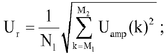
where Ur indicates the valid values of the amplitudes of the harmonics within the preset resonance frequency band [fmin, fmax], N1 indicates the total number of resonances within the preset resonance frequency band, M1 indicates the number of resonances corresponding to a minimum allowable resonance frequency fmin, M2 indicates the number of resonances corresponding to a maximum allowable resonance frequency fmax, and Uamp(k) indicates the amplitude of the k-th harmonic. - The verifying module 324 is configured to verify whether the valid values of the amplitudes of the harmonics are not less than a preset harmonic threshold.
- The preset harmonic threshold may be an allowable harmonic amplitude of an internal unit of an inverter in the grid-connected generation system, which is referred to as Umin, and the preset harmonic threshold may be determined based on a specific model number of the grid-connected inverter and grid parameters, which is not limited in the present disclosure.
- In the embodiment, in a case that it is verified that the valid values of the amplitudes of the harmonics are not less than the preset harmonic threshold, it is indicated that a resonance occurs in the grid-connected generation system currently.
- According to the analysis above, as shown in
Figure 3 , a closed loop, i.e., a resonance amplitude control loop, is formed in the structure of the device according to the present disclosure, thereby adjusting the resonance in the grid-connected generation system dynamically, and ensuring a reliable and stable operation of the grid-connected generation system. - The
error calculation module 325 is configured to calculate differences between the valid values of the amplitudes of the harmonics and the preset harmonic threshold to obtain input errors. - According to the analysis above, the input error equals the difference of the preset harmonic threshold minus the valid value of the amplitude of the harmonic, which is not limited.
- The
control acquiring module 326 is configured to adjust the input errors in proportion or proportion-integral to obtain current output controls. - The
amplitude clipping module 327 is configured to clip amplitudes of the current output controls to obtain current corrections of the parameters of the inverters in the grid-connected generation system. - In the embodiment, the amplitudes of the current output controls may be clipped using the above formula (4), a specific process may be referred to the description of the corresponding part of the above method embodiment, which is not described in the embodiment. The ways for clipping the amplitudes are not limited to the above-described ways, any way obtained by those skilled in the art without any creative work falls within the scope of protection of the present disclosure.
- In addition, in order to adjust the parameters of the inverters in the above-described embodiments, for the inverters, the adjusting module 340 may include a
first adjusting unit 341, asecond adjusting unit 342 and athird adjusting unit 343, as shown inFigure 4 . - The
first adjusting unit 341 is configured to adjust bandwidths of the inverters using the current corrections and a preset adjustment formula, and the preset adjustment formula may be:
where kp indicates a proportion control parameter, ΔUout indicates the current corrections, and kpmin indicates minimum allowable adjustment values of the bandwidths of the inverters. - The
second adjusting unit 342 is configured to adjust active damping coefficients of the inverters using a preset active damping algorithm and the current corrections. - In the embodiment, the active damping adjustment may be performed using the above formula (6), and a specific process may be referred to the description of the corresponding part of the above method embodiment, which is not described in the embodiment.
- The
third adjusting unit 343 is configured to transmit respectively the current corrections to the inverters to control the inactive damping resistor to be connected to a respective one of the inverters. - In order to avoid a system loss since the inactive damping resistor is connected to an control circuit of the inverter, the inactive damping resistor may be disconnected in a case that it is verified that the resonance does not occur in the grid-connected generation system, that is, the valid values of the amplitudes of the harmonics are less than the preset harmonic threshold.
- In addition, in a practical application, the first adjusting unit, the second adjusting unit and the third adjusting unit may be triggered according to a preset priority, and a specific order of priority is not limited in the present disclosure.
- Optionally, as shown in
Figure 4 , the device may further include a timer 350 (not shown inFigure 4 ) and astorage module 360. - The
timer 350 is configured to track the correction effect of the parameters of the inverters. The timer is started once the parameters of the inverters are adjusted using the first adjusting unit, the second adjusting unit and/or the third adjusting unit; and it is determined whether the valid values Ur of the corrected amplitudes of the harmonics of the current sample voltage changes in a real time manner within a predetermined period of time. - As shown in
Figure 4 , in a case that the verifying module 324 verifies that the resonance occurs in the grid-connected generation system, a switch S is controlled to switch from the left side to the right side, theerror calculation module 325 calculates the received valid values of the amplitudes of the harmonics to obtain input errors and transmits the input errors to thecontrol acquiring module 326. InFigure 4 , the input errors are adjusted in a proportion control to obtain current output controls U0, and then amplitudes of the current output controls U0 are clipped by theamplitude clipping module 327 to obtain current corrections ΔUout. The adjusting module 340 may be connected to thefirst adjusting unit 341, thesecond adjusting unit 342 and thethird adjusting unit 343 sequentially according to a preset priority Sm, thereby adjusting the parameters of the grid-connected inverter. - The
storage module 360 is configured to perform a power failure protection on the corrected parameters of the inverters in a case that the valid values of the amplitudes of the harmonics are reduced gradually and are less than the preset harmonic threshold Urmin, and the related parameters are directly called from the storage module once the grid-connected generation system is powered, thereby preventing a resonance from occurring once more. - Optionally, the
storage module 360 may be a non-volatile ferroelectric RAM (FRAM), i.e., a random access memory, specific functions and features thereof may be referred to the conventional FRAM, which is not described in the embodiment. - According to the analysis above, after the parameters of the inverters are adjusted, in a case that the valid values Ur of the corrected amplitudes of the harmonics are reduced gradually and are less than Urmin after the preset period of time, the
storage module 360 is triggered to perform a power failure protection on the corrected parameters of the grid-connected inverters. In a case that the Ur is not reduced or is still greater than Urmax after the preset period of time, that is to say, the resonance cannot be suppressed by correcting the parameters and the resonance becomes increasingly severe. In order to protect the related devices such as an alternate current capacitor, theprotection control module 370 may be directly triggered to transmit a protection signal to the inverters to control the inverters to stop operating. - In summary, in the embodiments of the present disclosure, the current sample voltage of the preset sample point of the grid-connected generation system is monitored in a real time manner; the amplitudes of the harmonics of the current sample voltage are acquired using the preset algorithm; it is verified whether the resonance occurs in the grid-connected generation system currently based on the acquired amplitudes of e the harmonics; in a case that the resonance occurs in the grid-connected generation system, the current corrections of the parameters of the inverters in the grid-connected generation system are acquired according to a preset rule; and the parameters of the inverters are adjusted using the current corrections and a selected resonance suppressing algorithm until the resonance disappears in the grid-connected generation system. It follows that, according to the present disclosure, the resonance point of the grid-connected generation system is adjusted dynamically to suppress the resonance occurred in the grid-connected generation system, thereby ensuring a reliable and stable operation of the grid-connected generation system.
- Finally, it should be noted that, in the above-described embodiments, the relationship terminologies such as "first", "second" and the like are only used herein to distinguish one operation, unit or module from another, rather than to necessitate or imply that the actual relationship or order exists between the units, operations or modules. Furthermore, the terms such as "include", "comprise" or any other variants thereof are intended to be non-exclusive. Therefore, the process, method, or system including a series of elements includes not only the elements but also other elements that are not enumerated, or further includes the elements inherent for the process, method, or system. Unless expressively limited otherwise, the statement "comprising (including) one..." does not exclude the case that other similar elements may exist in the process, method, or system.
- Various embodiments of the specification are described in a progressive way, with an emphasis placed on explaining the difference between each embodiment and the other embodiments. The same or similar parts among the embodiments can be referred to each other. For the device according to the embodiments, the corresponding descriptions are relatively simple because the device corresponds to the methods disclosed in the embodiments. The relevant portions may be referred to the description of the method parts.
- The above illustration of the disclosed embodiments enables those skilled in the art to implement or practice the present disclosure. Many changes to these embodiments are apparent for those skilled in the art, and general principles defined herein can be implemented in other embodiments without departing the spirit or scope of the present disclosure. Hence, the present disclosure is not limited to the embodiments disclosed herein, but is to conform to the widest scope consistent with principles and novel features disclosed herein.
Claims (10)
- A method for monitoring and suppressing a resonance applied to a grid-connected generation system, wherein the method comprises:monitoring a current sample voltage of a preset sample point of the grid-connected generation system;acquiring amplitudes of harmonics of the current sample voltage using a preset algorithm;verifying whether a resonance occurs in the grid-connected generation system based on the acquired amplitudes of the harmonics; andin a case that the resonance occurs in the grid-connected generation system, acquiring current corrections of parameters of inverters in the grid-connected generation system according to a preset rule, and adjusting the parameters of the inverters using the current corrections and a selected resonance suppressing algorithm until the resonance disappears in the grid-connected generation system.
- The method according to claim 1, wherein the acquiring amplitudes of harmonics of the current sample voltage using a preset algorithm comprises:calculating frequency domain values corresponding to the harmonics of the current sample voltage using an FFT algorithm formula, wherein the FFT algorithm formula is:
 calculating the amplitudes of the harmonics using the frequency domain values and a preset harmonic extracting formula, wherein the preset harmonic extracting formula is:
- The method according to claim 2, wherein the verifying whether a resonance occurs in the grid-connected generation system based on the acquired amplitudes of the harmonics comprises:calculating valid values of the amplitudes of the harmonics within a preset resonance frequency band using the amplitudes of the harmonics and a preset valid value calculation formula, wherein the preset valid value calculation formula is:
 verifying whether the valid values of the amplitudes of the harmonics are not less than a preset harmonic threshold,wherein it is determined that the resonance occurs in the grid-connected generation system in a case that the valid values of the amplitudes of the harmonics are not less than the preset harmonic threshold.
 - The method according to claim 3, wherein the acquiring current corrections of parameters of inverters in the grid-connected generation system according to a preset rule comprises:calculating differences between the valid values of the amplitudes of the harmonics and the preset harmonic threshold to obtain input errors;adjusting the input errors in proportion or proportion-integral to obtain current output controls; andclipping amplitudes of the current output controls to obtain the current corrections of the parameters of the inverters in the grid-connected generation system.
- The method according to any one of claims 1 to 4, wherein the adjusting the parameters of the inverters using the current corrections and a preset resonance suppressing algorithm comprises:adjusting bandwidths of the inverters using the current corrections and a preset adjustment formula, wherein the preset adjustment formula is:
 adjusting active damping coefficients of the inverters using a pre-stored active damping algorithm and the current corrections; and/ortransmitting respectively the current corrections to the inverters to control an inactive damping resistor to be connected to a respective one of the inverters.
 - The method according to claim 5, wherein after the adjusting the parameters of the inverters using the current corrections and a preset resonance suppressing algorithm, the method further comprises:controlling the inverters of the grid-connected generation system to stop operating in a case that the resonance does not disappear in the grid-connected generation system after a preset period of time.
- The method according to claim 5, wherein in a case that the resonance disappears in the grid-connected generation system, the method further comprises:performing a power failure protection on the adjusted parameters of the inverters.
- A device for monitoring and suppressing a resonance applied to a grid-connection generation system, wherein the device comprises:a sample conditioning circuit connected to a preset sample point of the grid-connected generation system and configured to monitor a current sample voltage of the preset sample point;a controller connected to the sample conditioning circuit and configured to acquire amplitudes of harmonics of the current sample voltage using a preset algorithm, verify whether a resonance occurs in the grid-connected generation system based on the acquired amplitudes of the harmonics, and acquire current corrections of parameters of inverters in the grid-connected generation system according to a preset rule in a case that the resonance occurs in the grid-connected generation system;a communication bus connected to the controller and the inverters in the grid-connected generation system and configured to transmit the current corrections acquired by the controller to the inverters respectively; andan adjusting module connected to the controller and the inverters and configured to adjust the parameters of the inverters using the current corrections and a preset resonance suppressing algorithm until the resonance disappears in the grid-connected generation system.
- The device according to claim 8, wherein the controller comprises:a frequency domain calculation module configured to calculate frequency domain values corresponding to the current sample voltage using an FFT algorithm formula, wherein the FFT algorithm formula is:
 an amplitude calculation module configured to calculate the amplitudes of the harmonics using the frequency domain values and a preset harmonic extracting formula, wherein the preset harmonic extracting formula is:
 a valid value calculation module configured to calculate valid values of the amplitudes of the harmonics within a preset resonance frequency band using the amplitudes of the harmonics and a preset valid value calculation formula, wherein the preset valid value calculation formula is:
 a verifying module configured to verify whether the valid values of the amplitudes of the harmonics are not less than a preset harmonic threshold;an error calculation module configured to calculate differences between the valid values of the amplitude of the harmonics and the preset harmonic threshold to obtain input errors;a control acquiring module configured to adjust the input errors in proportion or proportion-integral to obtain current output controls; andan amplitude clipping module configured to clip amplitudes of the current output controls to obtain the current corrections of the parameters of the inverters in the grid-connected generation system.
 - The device according to claim 8 or 9, wherein the adjusting module comprises:a first adjusting unit configured to adjust bandwidths of the inverters using the current corrections and a preset adjustment formula, wherein the preset adjustment formula is:
 a second adjusting unit configured to adjust active damping coefficients of the inverters using a preset active damping algorithm and the current corrections; anda third adjusting unit configured to transmit respectively the current corrections to the inverters to control an inactive damping resistor to be connected to a respective one of the inverters.
Applications Claiming Priority (2)
| Application Number | Priority Date | Filing Date | Title |
|---|---|---|---|
| CN201410465702.7A CN104201720B (en) | 2014-09-12 | 2014-09-12 | The control method of a kind of grid-connected system resonance suppression and device |
| CN201410465695.0A CN104201916B (en) | 2014-09-12 | 2014-09-12 | A kind of combining inverter resonance suppressing method and device |
Publications (2)
| Publication Number | Publication Date |
|---|---|
| EP3016256A1 true EP3016256A1 (en) | 2016-05-04 |
| EP3016256B1 EP3016256B1 (en) | 2022-03-09 |
Family
ID=54145607
Family Applications (1)
| Application Number | Title | Priority Date | Filing Date |
|---|---|---|---|
| EP15184730.8A Active EP3016256B1 (en) | 2014-09-12 | 2015-09-10 | Method and device for monitoring and suppressing resonance |
Country Status (4)
| Country | Link |
|---|---|
| US (1) | US10003198B2 (en) |
| EP (1) | EP3016256B1 (en) |
| JP (1) | JP6391542B2 (en) |
| ES (1) | ES2910456T3 (en) |
Families Citing this family (23)
| Publication number | Priority date | Publication date | Assignee | Title |
|---|---|---|---|---|
| US10331094B2 (en) * | 2014-01-30 | 2019-06-25 | Meidensha Corporation | Periodic external disturbance suppression control device |
| DE102016108394A1 (en) * | 2016-05-06 | 2017-11-09 | Wobben Properties Gmbh | Method for compensating feed-in currents of a wind farm |
| US10666127B2 (en) * | 2017-08-14 | 2020-05-26 | Ge Global Sourcing Llc | Power system and method |
| US10348184B2 (en) * | 2017-08-14 | 2019-07-09 | Ge Global Sourcing Llc | Power system and an associated method thereof |
| CN108493994B (en) * | 2018-03-28 | 2021-08-20 | 深圳市伊力科电源有限公司 | Feed network type inverter power supply control method and device |
| US10924014B2 (en) * | 2019-03-04 | 2021-02-16 | Alpha And Omega Semiconductor (Cayman) Ltd. | Switching regulator controller dynamic output voltage adjustment |
| CN112448391B (en) * | 2019-09-02 | 2025-10-21 | 中国电力科学研究院有限公司 | A method and system for controlling inverse time overcurrent relay protection |
| CN112701981B (en) * | 2020-12-15 | 2022-11-15 | 东风汽车集团有限公司 | Automatic adjusting method for inversion frequency of motor controller and related equipment |
| CN112737118B (en) * | 2020-12-26 | 2023-03-24 | 广东电网有限责任公司电力科学研究院 | Urban power distribution network harmonic instability monitoring device and method |
| CN114156947B (en) * | 2021-12-10 | 2024-08-16 | 润电能源科学技术有限公司 | Resonance monitoring system of power grid |
| JP7661263B2 (en) * | 2022-03-15 | 2025-04-14 | 株式会社東芝 | Power System |
| CN114865654A (en) * | 2022-04-28 | 2022-08-05 | 阳光电源(上海)有限公司 | Inverter and grid-connected regulation and control method thereof |
| CN114995579B (en) * | 2022-06-17 | 2023-03-24 | 河海大学 | Improved butterfly algorithm integrating memory and natural selection to realize Z-source photovoltaic MPPT (maximum Power Point tracking) |
| CN115021261A (en) * | 2022-07-19 | 2022-09-06 | 广东电网有限责任公司 | Harmonic current suppression method and device, electronic equipment and storage medium |
| CN115436703B (en) * | 2022-09-28 | 2025-02-18 | 美世乐(广东)新能源科技有限公司 | A method and device for protecting inverter from resonance with power grid |
| CN115693622B (en) * | 2022-11-16 | 2024-12-20 | 国网浙江省电力有限公司舟山供电公司 | A protection method for flexible DC transmission system based on high frequency component detection |
| CN115833219B (en) * | 2022-12-17 | 2025-10-10 | 国网福建省电力有限公司电力科学研究院 | Method for suppressing mid- and high-frequency resonance based on impedance sensitivity analysis |
| CN116400135B (en) * | 2023-04-06 | 2026-03-24 | 阳光电源(南京)有限公司 | A method and device for detecting resonance in a weak power grid |
| CN116960990B (en) * | 2023-09-21 | 2023-12-12 | 国网湖北省电力有限公司 | Method, device, system and storage medium for suppressing broadband oscillation of power system |
| CN117096938B (en) * | 2023-10-19 | 2024-03-12 | 国网浙江省电力有限公司象山县供电公司 | Inverter output power quality adaptive control method, device and computer equipment |
| CN119275867B (en) * | 2024-12-09 | 2025-06-17 | 国网浙江省电力有限公司宁波供电公司 | A method and system for suppressing synchronous resonance of a wind farm |
| CN120430635B (en) * | 2025-07-04 | 2025-11-14 | 广东运峰电力安装有限公司 | A Smart Method for Power Security Situation Assessment Based on Multi-Source Sensor Networks |
| CN120601536B (en) * | 2025-08-08 | 2025-10-17 | 国网浙江省电力有限公司杭州市富阳区供电公司 | A method and system for dynamically suppressing high-frequency resonance of a direct-drive wind turbine grid-connected inverter |
Citations (3)
| Publication number | Priority date | Publication date | Assignee | Title |
|---|---|---|---|---|
| EP0491691A1 (en) * | 1989-09-11 | 1992-07-01 | Siemens Ag | Process and device for determining parameters governing resonance in a power-converter power supply. |
| US8780592B1 (en) * | 2011-07-11 | 2014-07-15 | Chilicon Power, LLC | Systems and methods for increasing output current quality, output power, and reliability of grid-interactive inverters |
| WO2014125649A1 (en) * | 2013-02-18 | 2014-08-21 | 富士電機株式会社 | Resonance suppression device |
Family Cites Families (15)
| Publication number | Priority date | Publication date | Assignee | Title |
|---|---|---|---|---|
| JPS59149746A (en) * | 1983-02-10 | 1984-08-27 | 株式会社東芝 | Resonance preventing device of power system |
| JPH0729608U (en) * | 1993-11-04 | 1995-06-02 | 日新電機株式会社 | Output limiter circuit of power conversion circuit |
| JP2002325358A (en) * | 2001-04-27 | 2002-11-08 | Japan Science & Technology Corp | Distributed power supply system and harmonic suppression power supply control method |
| JP5047829B2 (en) * | 2008-02-06 | 2012-10-10 | シャープ株式会社 | Power system |
| JP5670904B2 (en) * | 2008-09-26 | 2015-02-18 | エクスレント エナジー テクノロジーズ リミテッド ライアビリティ カンパニー | Adaptive generation and control of arbitrary electrical waveforms in a grid-coupled power conversion system |
| CN103023290B (en) | 2011-09-23 | 2015-11-25 | 台达电子企业管理(上海)有限公司 | Medium voltage converter drive system and total harmonic distortion compensating control method |
| ES2758573T3 (en) | 2011-11-04 | 2020-05-05 | Abb Schweiz Ag | Method and apparatus for detecting the island formation conditions of a distributed network |
| JP6021121B2 (en) * | 2012-02-29 | 2016-11-09 | 三菱重工業株式会社 | Wind turbine generator control device, wind turbine generator, wind farm, and wind turbine generator control method |
| CA2831361C (en) * | 2012-10-31 | 2016-10-04 | Hitachi, Ltd. | Power generation system, backup power supply, data center installation method, power generation system controller, power system, and power generation system operating method |
| CN103023364B (en) | 2012-11-26 | 2015-01-21 | 华为技术有限公司 | Photovoltaic inverter leak current regulation inhibiting method and device |
| CN103117559B (en) | 2013-03-08 | 2015-04-15 | 深圳市英威腾电气股份有限公司 | Method, device and inverter for improving grid-tied electric energy quality |
| CN103219745B (en) | 2013-04-19 | 2014-12-03 | 浙江埃菲生能源科技有限公司 | Grid-connected inverter control algorithm based on orthogonal sine wave extractor |
| CN103401242B (en) | 2013-07-15 | 2016-03-09 | 合肥工业大学 | A kind of control method of multi-inverter system resonance restraining device |
| CN103701128A (en) | 2013-12-31 | 2014-04-02 | 国家电网公司 | LCL parallel resonance restraining method and inverter |
| CN103746587A (en) | 2014-01-22 | 2014-04-23 | 开封光利高科实业有限责任公司 | Control damping method applied to the resonance inhibition of LLCL single-phase grid connected inverter |
-
2015
- 2015-09-10 JP JP2015178474A patent/JP6391542B2/en active Active
- 2015-09-10 US US14/850,649 patent/US10003198B2/en active Active
- 2015-09-10 ES ES15184730T patent/ES2910456T3/en active Active
- 2015-09-10 EP EP15184730.8A patent/EP3016256B1/en active Active
Patent Citations (3)
| Publication number | Priority date | Publication date | Assignee | Title |
|---|---|---|---|---|
| EP0491691A1 (en) * | 1989-09-11 | 1992-07-01 | Siemens Ag | Process and device for determining parameters governing resonance in a power-converter power supply. |
| US8780592B1 (en) * | 2011-07-11 | 2014-07-15 | Chilicon Power, LLC | Systems and methods for increasing output current quality, output power, and reliability of grid-interactive inverters |
| WO2014125649A1 (en) * | 2013-02-18 | 2014-08-21 | 富士電機株式会社 | Resonance suppression device |
Also Published As
| Publication number | Publication date |
|---|---|
| US10003198B2 (en) | 2018-06-19 |
| ES2910456T3 (en) | 2022-05-12 |
| EP3016256B1 (en) | 2022-03-09 |
| JP2016063742A (en) | 2016-04-25 |
| JP6391542B2 (en) | 2018-09-19 |
| US20160079758A1 (en) | 2016-03-17 |
Similar Documents
| Publication | Publication Date | Title |
|---|---|---|
| EP3016256B1 (en) | Method and device for monitoring and suppressing resonance | |
| CN104201916B (en) | A kind of combining inverter resonance suppressing method and device | |
| JP2016063742A5 (en) | ||
| TWI550993B (en) | Wind farm, method for controlling wind farm and wind power plant | |
| KR102115860B1 (en) | Method and apparatus for detecting voltage in the supply network | |
| EP3534480B1 (en) | Subsynchronous suppression method and apparatus, and controller for converter | |
| CN104638664B (en) | Wind park sub-synchronous oscillation guard method and protection device | |
| CN109617121B (en) | Wind power grid-connected system safe operation method and system for subsynchronous oscillation | |
| TW201541796A (en) | Method for operating a wind turbine and/or a wind power plant, and regulating and/or controlling devices and wind turbines and wind power plants | |
| CN103760434A (en) | Self-adaption phase deviation island detection method based on fuzzy control | |
| WO2023032554A1 (en) | Power grid monitoring system and power grid monitoring method | |
| JPWO2020144841A1 (en) | Power conversion system and power conversion device | |
| EP2991209A1 (en) | Method for controlling shutdown of photovoltaic inverters, system thereof, and photovoltaic power generation system | |
| EP4019768A1 (en) | Method and system for determining a setpoint signal of a wind energy conversion system | |
| CN117829616A (en) | Method and system for evaluating voltage support capability of new energy stations under asymmetric faults | |
| JP5570929B2 (en) | Power converter and power supply system | |
| CN113972634B (en) | A Microgrid Differential Protection Method Based on Adaptive Zero-sequence Energy Injection | |
| CN115833166B (en) | Resonance protection design method for grid-connected inverter | |
| CN107658898B (en) | Photovoltaic power generation station-level anti-islanding protection method and system | |
| CN109075696B (en) | Method for operating an inverter system and inverter system operating according to said method | |
| CN112928742A (en) | Direct-current bus overvoltage protection method of converter and corresponding controller | |
| CN104578047B (en) | Method and device for controlling micro grid system | |
| JP5857206B2 (en) | Grid interconnection device and grid interconnection system | |
| CN121036160A (en) | Applicability Analysis Method and System for Power Directional Components of New Energy Transmission via Flexible Direct Current Transmission | |
| CN105186557A (en) | Grid-connected inverter control system and control method thereof |
Legal Events
| Date | Code | Title | Description |
|---|---|---|---|
| PUAI | Public reference made under article 153(3) epc to a published international application that has entered the european phase |
Free format text: ORIGINAL CODE: 0009012 |
|
| AK | Designated contracting states |
Kind code of ref document: A1 Designated state(s): AL AT BE BG CH CY CZ DE DK EE ES FI FR GB GR HR HU IE IS IT LI LT LU LV MC MK MT NL NO PL PT RO RS SE SI SK SM TR |
|
| AX | Request for extension of the european patent |
Extension state: BA ME |
|
| STAA | Information on the status of an ep patent application or granted ep patent |
Free format text: STATUS: REQUEST FOR EXAMINATION WAS MADE |
|
| 17P | Request for examination filed |
Effective date: 20161028 |
|
| RBV | Designated contracting states (corrected) |
Designated state(s): AL AT BE BG CH CY CZ DE DK EE ES FI FR GB GR HR HU IE IS IT LI LT LU LV MC MK MT NL NO PL PT RO RS SE SI SK SM TR |
|
| STAA | Information on the status of an ep patent application or granted ep patent |
Free format text: STATUS: EXAMINATION IS IN PROGRESS |
|
| 17Q | First examination report despatched |
Effective date: 20171121 |
|
| GRAP | Despatch of communication of intention to grant a patent |
Free format text: ORIGINAL CODE: EPIDOSNIGR1 |
|
| STAA | Information on the status of an ep patent application or granted ep patent |
Free format text: STATUS: GRANT OF PATENT IS INTENDED |
|
| RIC1 | Information provided on ipc code assigned before grant |
Ipc: H02M 1/00 20060101ALN20210831BHEP Ipc: G01R 23/20 20060101ALI20210831BHEP Ipc: H02J 3/38 20060101ALI20210831BHEP Ipc: H02J 3/01 20060101ALI20210831BHEP Ipc: H02M 1/12 20060101AFI20210831BHEP |
|
| INTG | Intention to grant announced |
Effective date: 20211001 |
|
| GRAS | Grant fee paid |
Free format text: ORIGINAL CODE: EPIDOSNIGR3 |
|
| GRAA | (expected) grant |
Free format text: ORIGINAL CODE: 0009210 |
|
| STAA | Information on the status of an ep patent application or granted ep patent |
Free format text: STATUS: THE PATENT HAS BEEN GRANTED |
|
| AK | Designated contracting states |
Kind code of ref document: B1 Designated state(s): AL AT BE BG CH CY CZ DE DK EE ES FI FR GB GR HR HU IE IS IT LI LT LU LV MC MK MT NL NO PL PT RO RS SE SI SK SM TR |
|
| REG | Reference to a national code |
Ref country code: GB Ref legal event code: FG4D |
|
| REG | Reference to a national code |
Ref country code: CH Ref legal event code: EP Ref country code: AT Ref legal event code: REF Ref document number: 1474963 Country of ref document: AT Kind code of ref document: T Effective date: 20220315 |
|
| REG | Reference to a national code |
Ref country code: IE Ref legal event code: FG4D |
|
| REG | Reference to a national code |
Ref country code: DE Ref legal event code: R096 Ref document number: 602015077368 Country of ref document: DE |
|
| REG | Reference to a national code |
Ref country code: ES Ref legal event code: FG2A Ref document number: 2910456 Country of ref document: ES Kind code of ref document: T3 Effective date: 20220512 |
|
| REG | Reference to a national code |
Ref country code: LT Ref legal event code: MG9D |
|
| REG | Reference to a national code |
Ref country code: NL Ref legal event code: MP Effective date: 20220309 |
|
| PG25 | Lapsed in a contracting state [announced via postgrant information from national office to epo] |
Ref country code: SE Free format text: LAPSE BECAUSE OF FAILURE TO SUBMIT A TRANSLATION OF THE DESCRIPTION OR TO PAY THE FEE WITHIN THE PRESCRIBED TIME-LIMIT Effective date: 20220309 Ref country code: RS Free format text: LAPSE BECAUSE OF FAILURE TO SUBMIT A TRANSLATION OF THE DESCRIPTION OR TO PAY THE FEE WITHIN THE PRESCRIBED TIME-LIMIT Effective date: 20220309 Ref country code: NO Free format text: LAPSE BECAUSE OF FAILURE TO SUBMIT A TRANSLATION OF THE DESCRIPTION OR TO PAY THE FEE WITHIN THE PRESCRIBED TIME-LIMIT Effective date: 20220609 Ref country code: LT Free format text: LAPSE BECAUSE OF FAILURE TO SUBMIT A TRANSLATION OF THE DESCRIPTION OR TO PAY THE FEE WITHIN THE PRESCRIBED TIME-LIMIT Effective date: 20220309 Ref country code: HR Free format text: LAPSE BECAUSE OF FAILURE TO SUBMIT A TRANSLATION OF THE DESCRIPTION OR TO PAY THE FEE WITHIN THE PRESCRIBED TIME-LIMIT Effective date: 20220309 Ref country code: BG Free format text: LAPSE BECAUSE OF FAILURE TO SUBMIT A TRANSLATION OF THE DESCRIPTION OR TO PAY THE FEE WITHIN THE PRESCRIBED TIME-LIMIT Effective date: 20220609 |
|
| REG | Reference to a national code |
Ref country code: AT Ref legal event code: MK05 Ref document number: 1474963 Country of ref document: AT Kind code of ref document: T Effective date: 20220309 |
|
| PG25 | Lapsed in a contracting state [announced via postgrant information from national office to epo] |
Ref country code: LV Free format text: LAPSE BECAUSE OF FAILURE TO SUBMIT A TRANSLATION OF THE DESCRIPTION OR TO PAY THE FEE WITHIN THE PRESCRIBED TIME-LIMIT Effective date: 20220309 Ref country code: GR Free format text: LAPSE BECAUSE OF FAILURE TO SUBMIT A TRANSLATION OF THE DESCRIPTION OR TO PAY THE FEE WITHIN THE PRESCRIBED TIME-LIMIT Effective date: 20220610 Ref country code: FI Free format text: LAPSE BECAUSE OF FAILURE TO SUBMIT A TRANSLATION OF THE DESCRIPTION OR TO PAY THE FEE WITHIN THE PRESCRIBED TIME-LIMIT Effective date: 20220309 |
|
| PG25 | Lapsed in a contracting state [announced via postgrant information from national office to epo] |
Ref country code: NL Free format text: LAPSE BECAUSE OF FAILURE TO SUBMIT A TRANSLATION OF THE DESCRIPTION OR TO PAY THE FEE WITHIN THE PRESCRIBED TIME-LIMIT Effective date: 20220309 |
|
| PG25 | Lapsed in a contracting state [announced via postgrant information from national office to epo] |
Ref country code: SM Free format text: LAPSE BECAUSE OF FAILURE TO SUBMIT A TRANSLATION OF THE DESCRIPTION OR TO PAY THE FEE WITHIN THE PRESCRIBED TIME-LIMIT Effective date: 20220309 Ref country code: SK Free format text: LAPSE BECAUSE OF FAILURE TO SUBMIT A TRANSLATION OF THE DESCRIPTION OR TO PAY THE FEE WITHIN THE PRESCRIBED TIME-LIMIT Effective date: 20220309 Ref country code: RO Free format text: LAPSE BECAUSE OF FAILURE TO SUBMIT A TRANSLATION OF THE DESCRIPTION OR TO PAY THE FEE WITHIN THE PRESCRIBED TIME-LIMIT Effective date: 20220309 Ref country code: PT Free format text: LAPSE BECAUSE OF FAILURE TO SUBMIT A TRANSLATION OF THE DESCRIPTION OR TO PAY THE FEE WITHIN THE PRESCRIBED TIME-LIMIT Effective date: 20220711 Ref country code: EE Free format text: LAPSE BECAUSE OF FAILURE TO SUBMIT A TRANSLATION OF THE DESCRIPTION OR TO PAY THE FEE WITHIN THE PRESCRIBED TIME-LIMIT Effective date: 20220309 Ref country code: CZ Free format text: LAPSE BECAUSE OF FAILURE TO SUBMIT A TRANSLATION OF THE DESCRIPTION OR TO PAY THE FEE WITHIN THE PRESCRIBED TIME-LIMIT Effective date: 20220309 Ref country code: AT Free format text: LAPSE BECAUSE OF FAILURE TO SUBMIT A TRANSLATION OF THE DESCRIPTION OR TO PAY THE FEE WITHIN THE PRESCRIBED TIME-LIMIT Effective date: 20220309 |
|
| PG25 | Lapsed in a contracting state [announced via postgrant information from national office to epo] |
Ref country code: PL Free format text: LAPSE BECAUSE OF FAILURE TO SUBMIT A TRANSLATION OF THE DESCRIPTION OR TO PAY THE FEE WITHIN THE PRESCRIBED TIME-LIMIT Effective date: 20220309 Ref country code: IS Free format text: LAPSE BECAUSE OF FAILURE TO SUBMIT A TRANSLATION OF THE DESCRIPTION OR TO PAY THE FEE WITHIN THE PRESCRIBED TIME-LIMIT Effective date: 20220709 Ref country code: AL Free format text: LAPSE BECAUSE OF FAILURE TO SUBMIT A TRANSLATION OF THE DESCRIPTION OR TO PAY THE FEE WITHIN THE PRESCRIBED TIME-LIMIT Effective date: 20220309 |
|
| REG | Reference to a national code |
Ref country code: DE Ref legal event code: R097 Ref document number: 602015077368 Country of ref document: DE |
|
| PLBE | No opposition filed within time limit |
Free format text: ORIGINAL CODE: 0009261 |
|
| STAA | Information on the status of an ep patent application or granted ep patent |
Free format text: STATUS: NO OPPOSITION FILED WITHIN TIME LIMIT |
|
| PG25 | Lapsed in a contracting state [announced via postgrant information from national office to epo] |
Ref country code: DK Free format text: LAPSE BECAUSE OF FAILURE TO SUBMIT A TRANSLATION OF THE DESCRIPTION OR TO PAY THE FEE WITHIN THE PRESCRIBED TIME-LIMIT Effective date: 20220309 |
|
| 26N | No opposition filed |
Effective date: 20221212 |
|
| PG25 | Lapsed in a contracting state [announced via postgrant information from national office to epo] |
Ref country code: SI Free format text: LAPSE BECAUSE OF FAILURE TO SUBMIT A TRANSLATION OF THE DESCRIPTION OR TO PAY THE FEE WITHIN THE PRESCRIBED TIME-LIMIT Effective date: 20220309 |
|
| PG25 | Lapsed in a contracting state [announced via postgrant information from national office to epo] |
Ref country code: MC Free format text: LAPSE BECAUSE OF FAILURE TO SUBMIT A TRANSLATION OF THE DESCRIPTION OR TO PAY THE FEE WITHIN THE PRESCRIBED TIME-LIMIT Effective date: 20220309 |
|
| REG | Reference to a national code |
Ref country code: CH Ref legal event code: PL |
|
| GBPC | Gb: european patent ceased through non-payment of renewal fee |
Effective date: 20220910 |
|
| REG | Reference to a national code |
Ref country code: BE Ref legal event code: MM Effective date: 20220930 |
|
| P01 | Opt-out of the competence of the unified patent court (upc) registered |
Effective date: 20230426 |
|
| PG25 | Lapsed in a contracting state [announced via postgrant information from national office to epo] |
Ref country code: LU Free format text: LAPSE BECAUSE OF NON-PAYMENT OF DUE FEES Effective date: 20220910 |
|
| PG25 | Lapsed in a contracting state [announced via postgrant information from national office to epo] |
Ref country code: LI Free format text: LAPSE BECAUSE OF NON-PAYMENT OF DUE FEES Effective date: 20220930 Ref country code: IE Free format text: LAPSE BECAUSE OF NON-PAYMENT OF DUE FEES Effective date: 20220910 Ref country code: CH Free format text: LAPSE BECAUSE OF NON-PAYMENT OF DUE FEES Effective date: 20220930 |
|
| PG25 | Lapsed in a contracting state [announced via postgrant information from national office to epo] |
Ref country code: BE Free format text: LAPSE BECAUSE OF NON-PAYMENT OF DUE FEES Effective date: 20220930 |
|
| PG25 | Lapsed in a contracting state [announced via postgrant information from national office to epo] |
Ref country code: GB Free format text: LAPSE BECAUSE OF NON-PAYMENT OF DUE FEES Effective date: 20220910 |
|
| PG25 | Lapsed in a contracting state [announced via postgrant information from national office to epo] |
Ref country code: HU Free format text: LAPSE BECAUSE OF FAILURE TO SUBMIT A TRANSLATION OF THE DESCRIPTION OR TO PAY THE FEE WITHIN THE PRESCRIBED TIME-LIMIT; INVALID AB INITIO Effective date: 20150910 |
|
| PG25 | Lapsed in a contracting state [announced via postgrant information from national office to epo] |
Ref country code: CY Free format text: LAPSE BECAUSE OF FAILURE TO SUBMIT A TRANSLATION OF THE DESCRIPTION OR TO PAY THE FEE WITHIN THE PRESCRIBED TIME-LIMIT Effective date: 20220309 |
|
| PG25 | Lapsed in a contracting state [announced via postgrant information from national office to epo] |
Ref country code: MK Free format text: LAPSE BECAUSE OF FAILURE TO SUBMIT A TRANSLATION OF THE DESCRIPTION OR TO PAY THE FEE WITHIN THE PRESCRIBED TIME-LIMIT Effective date: 20220309 |
|
| PG25 | Lapsed in a contracting state [announced via postgrant information from national office to epo] |
Ref country code: MT Free format text: LAPSE BECAUSE OF FAILURE TO SUBMIT A TRANSLATION OF THE DESCRIPTION OR TO PAY THE FEE WITHIN THE PRESCRIBED TIME-LIMIT Effective date: 20220309 |
|
| PGFP | Annual fee paid to national office [announced via postgrant information from national office to epo] |
Ref country code: DE Payment date: 20250926 Year of fee payment: 11 |
|
| PGFP | Annual fee paid to national office [announced via postgrant information from national office to epo] |
Ref country code: IT Payment date: 20250826 Year of fee payment: 11 |
|
| PGFP | Annual fee paid to national office [announced via postgrant information from national office to epo] |
Ref country code: FR Payment date: 20250929 Year of fee payment: 11 |
|
| PG25 | Lapsed in a contracting state [announced via postgrant information from national office to epo] |
Ref country code: TR Free format text: LAPSE BECAUSE OF FAILURE TO SUBMIT A TRANSLATION OF THE DESCRIPTION OR TO PAY THE FEE WITHIN THE PRESCRIBED TIME-LIMIT Effective date: 20220309 |
|
| PGFP | Annual fee paid to national office [announced via postgrant information from national office to epo] |
Ref country code: ES Payment date: 20251103 Year of fee payment: 11 |