EP3016252A1 - Bearing device with energy harvesting means - Google Patents
Bearing device with energy harvesting means Download PDFInfo
- Publication number
- EP3016252A1 EP3016252A1 EP15186209.1A EP15186209A EP3016252A1 EP 3016252 A1 EP3016252 A1 EP 3016252A1 EP 15186209 A EP15186209 A EP 15186209A EP 3016252 A1 EP3016252 A1 EP 3016252A1
- Authority
- EP
- European Patent Office
- Prior art keywords
- bearing arrangement
- arrangement according
- generating system
- energy
- rotating part
- Prior art date
- Legal status (The legal status is an assumption and is not a legal conclusion. Google has not performed a legal analysis and makes no representation as to the accuracy of the status listed.)
- Granted
Links
- 238000003306 harvesting Methods 0.000 title description 5
- 238000004146 energy storage Methods 0.000 claims description 5
- 239000003990 capacitor Substances 0.000 claims description 4
- 230000036316 preload Effects 0.000 claims description 2
- 238000007789 sealing Methods 0.000 claims 2
- 239000002184 metal Substances 0.000 description 5
- 210000000078 claw Anatomy 0.000 description 3
- 230000005484 gravity Effects 0.000 description 3
- 230000005540 biological transmission Effects 0.000 description 2
- 230000010355 oscillation Effects 0.000 description 2
- 239000007787 solid Substances 0.000 description 2
- 230000001133 acceleration Effects 0.000 description 1
- 230000004308 accommodation Effects 0.000 description 1
- 230000006978 adaptation Effects 0.000 description 1
- 239000000428 dust Substances 0.000 description 1
- 230000005674 electromagnetic induction Effects 0.000 description 1
- 238000005516 engineering process Methods 0.000 description 1
- 230000003993 interaction Effects 0.000 description 1
Images


Classifications
-
- H—ELECTRICITY
- H02—GENERATION; CONVERSION OR DISTRIBUTION OF ELECTRIC POWER
- H02K—DYNAMO-ELECTRIC MACHINES
- H02K7/00—Arrangements for handling mechanical energy structurally associated with dynamo-electric machines, e.g. structural association with mechanical driving motors or auxiliary dynamo-electric machines
- H02K7/18—Structural association of electric generators with mechanical driving motors, e.g. with turbines
- H02K7/1807—Rotary generators
- H02K7/1846—Rotary generators structurally associated with wheels or associated parts
-
- F—MECHANICAL ENGINEERING; LIGHTING; HEATING; WEAPONS; BLASTING
- F16—ENGINEERING ELEMENTS AND UNITS; GENERAL MEASURES FOR PRODUCING AND MAINTAINING EFFECTIVE FUNCTIONING OF MACHINES OR INSTALLATIONS; THERMAL INSULATION IN GENERAL
- F16C—SHAFTS; FLEXIBLE SHAFTS; ELEMENTS OR CRANKSHAFT MECHANISMS; ROTARY BODIES OTHER THAN GEARING ELEMENTS; BEARINGS
- F16C19/00—Bearings with rolling contact, for exclusively rotary movement
- F16C19/22—Bearings with rolling contact, for exclusively rotary movement with bearing rollers essentially of the same size in one or more circular rows, e.g. needle bearings
- F16C19/34—Bearings with rolling contact, for exclusively rotary movement with bearing rollers essentially of the same size in one or more circular rows, e.g. needle bearings for both radial and axial load
- F16C19/38—Bearings with rolling contact, for exclusively rotary movement with bearing rollers essentially of the same size in one or more circular rows, e.g. needle bearings for both radial and axial load with two or more rows of rollers
- F16C19/383—Bearings with rolling contact, for exclusively rotary movement with bearing rollers essentially of the same size in one or more circular rows, e.g. needle bearings for both radial and axial load with two or more rows of rollers with tapered rollers, i.e. rollers having essentially the shape of a truncated cone
- F16C19/385—Bearings with rolling contact, for exclusively rotary movement with bearing rollers essentially of the same size in one or more circular rows, e.g. needle bearings for both radial and axial load with two or more rows of rollers with tapered rollers, i.e. rollers having essentially the shape of a truncated cone with two rows, i.e. double-row tapered roller bearings
- F16C19/386—Bearings with rolling contact, for exclusively rotary movement with bearing rollers essentially of the same size in one or more circular rows, e.g. needle bearings for both radial and axial load with two or more rows of rollers with tapered rollers, i.e. rollers having essentially the shape of a truncated cone with two rows, i.e. double-row tapered roller bearings in O-arrangement
-
- F—MECHANICAL ENGINEERING; LIGHTING; HEATING; WEAPONS; BLASTING
- F16—ENGINEERING ELEMENTS AND UNITS; GENERAL MEASURES FOR PRODUCING AND MAINTAINING EFFECTIVE FUNCTIONING OF MACHINES OR INSTALLATIONS; THERMAL INSULATION IN GENERAL
- F16C—SHAFTS; FLEXIBLE SHAFTS; ELEMENTS OR CRANKSHAFT MECHANISMS; ROTARY BODIES OTHER THAN GEARING ELEMENTS; BEARINGS
- F16C41/00—Other accessories, e.g. devices integrated in the bearing not relating to the bearing function as such
- F16C41/004—Electro-dynamic machines, e.g. motors, generators, actuators
-
- H—ELECTRICITY
- H02—GENERATION; CONVERSION OR DISTRIBUTION OF ELECTRIC POWER
- H02K—DYNAMO-ELECTRIC MACHINES
- H02K7/00—Arrangements for handling mechanical energy structurally associated with dynamo-electric machines, e.g. structural association with mechanical driving motors or auxiliary dynamo-electric machines
- H02K7/06—Means for converting reciprocating motion into rotary motion or vice versa
- H02K7/061—Means for converting reciprocating motion into rotary motion or vice versa using rotary unbalanced masses
Definitions
- the invention relates a bearing device provided with an energy harvesting means.
- the document WO 2014/108169 A1 relates to an end cap for a bearing assembly configured to be attached to a rotatable part of the bearing.
- a pendulum unit is attached to the centre axis of the end cap and is adapted to oscillate between two positions under the influence of gravity such that energy can be generated by an oscillation of the pendulum unit.
- the generator is configured to interact with a rotating target ring, encoder wheel or tone wheel such that the relative rotation of different parts of the bearing creates an oscillating current in a coil, which can be rectified for further use.
- Micro generating systems comprise at least an eccentric mass, a miniaturized claw pole generator, and an energy storage, wherein a gear box may be optionally provided between the eccentric mass and the generator.
- the document DE 10 2006 044 562 A1 discloses a further generator unit using the oscillating gravitational force for driving a pendulum to create energy for measuring tire pressure for vehicles.
- the invention seeks to overcome the drawbacks of the prior art by providing a bearing arrangement including an energy generating system which is cost saving, robust and scalable.
- the invention relates to a bearing arrangement including a rotating part and a non-rotating part, wherein the rotating part is configured to rotate relative to the non-rotating part with an essentially horizontal rotation axis.
- the energy generating system comprises at least one micro generator module including a housing, an eccentric mass mounted so as to be rotatable around an eccentric shaft in the housing, and a generator unit configured to generate electrical energy from the rotation of the eccentric shaft.
- the micro generator module with the separate generator housing may be easily mounted at suitable places on the rotating part of the bearing assembly, is robust and versatile.
- the energy generating system is modular in the sense that multiple micro generating modules may be used in a system and attached to the rotating part of the bearing if necessary.
- the eccentric shaft of the micro generator modules is arranged in a radial direction with regard to the axis of rotation of the bearing assembly as a whole.
- the eccentric shaft axis of rotation is essentially perpendicular to the bearing axis of rotation.
- housings of the micro generating system which are essentially cylindrical, wherein the radially outer surface of the cylindrical housings may be optionally provided with O-rings preventing the sliding of the micro generating modules within their accommodation.
- the generator system comprises multiple micro generator units as described above, arranged in an arc-shaped outer housing configured to be attached to the rotating part of the bearing assembly.
- the curvature of the arc-shaped plastic housing can be adapted to the bearing to which the system shall be applied.
- the modular nature of the energy generating system facilitates the adaptation to different bearing types in that only the outer housing has to be adapted to the mounting environment and to the number of micro-generating systems to be accommodated.
- the outer housing of the energy generating system includes a circuit board with electronic devices driven by the energy generated by the micro generating system and optionally with energy storage means such as a capacitor or the like.
- the devices mounted on the printed circuit board may include a microprocessor, temperature sensors, pressure sensors, acceleration sensors, vibration sensors, acoustic emission sensors and/or wireless transmitters to transmit the data calculated by the microcontroller to the outside.
- the energy generating system may be provided in addition and separate from a unit for transmitting the signals to the outside.
- the bearing assembly is configured as a railway axle bearing and the energy generator assembly is mounted in an end cap of the axle bearing. Further details on the sensor system are disclosed e.g. in WO 2014/154259 , which is included herein by reference.
- Figures 1 and 2 show a railway axle bearing unit including an end cap 10 fixed with three bolts 12 on an axial end face of an axle 13 so as to preload and retain a bearing 5.
- the bearing is double-row taper roller bearing in the depicted example, comprising a non-rotating outer ring 7 which is mounted in a housing 20 known as a saddle adapter.
- the bearing further has first and second inner rings 8a, 8b which are mounted to the rotational axle 13. Between the outer ring 7 and the first and second inner rings 8a, 8b, first and second rows 9a, 9b of tapered rollers are accommodated.
- the end cap 10 comprises a solid metal base part and arc-shaped cover plates 16a, 16b fixed to the metal base part by means of screws 17.
- the metal base part 14 is illustrated in a cross-sectional view in Figure 3 .
- An outer side of the metal base part 14 facing away from the bearing unit 5 in the assembled configuration is provided with an angular, groove-like recess 18 which is symmetric with respect to a centre of rotation of the end cap 10.
- the recess 18 is delimited by a metal wall 19 of substantially constant thickness on the radially outer side and by a solid bulk body of a base part 14 on the radially inner side.
- cover plates 16a, 16b cover the groove-like recess 18 which is machined into the base part 14 around its entire circumference and holes 12a for the bolts 12 and for the screws fixing the cover plates 16a, 16b are provided for assembly and mounting of the end cap 10.
- the recess accommodates a sensor unit 22 underneath the cover plate 16a.
- the sensor unit 22 includes a micro-processor, a transmitter with an antenna part projecting through a window over the cover plate 16a, sensors and means for storing identification information and other information relating to the operation of the bearing.
- the cover plate 16b covers the energy generating system according to the invention, which supplies the energy needed by the sensor unit 22.
- FIG 4 illustrates the end cap 10 with the cover plate 16b removed.
- the energy generating system includes a plurality of micro-generators or micro generator modules 24, each having an eccentric mass 26 at an eccentric shaft 28 carrying the eccentric mass 26.
- the eccentric shafts 28 are aligned radially with regard to the rotation axis of the bearing in the mounted configuration of the end cap 10.
- FIG. 5 A further example of a micro generator module according to the invention is illustrated in more detail in Figure 5 .
- the eccentric shaft 28 is connected via gears forming a transmission to a generator 30.
- the generator may be executed as a claw pole generator comprising a magnetic rotor and a number of claw poles.
- the magnetic rotor is coupled to the eccentric shaft 28, through the transmission, and generates electric current via electromagnetic induction in the known manner.
- the generator 30 and the eccentric shaft 28 are accommodated a substantially cylindrical micro-generator housing 32 such that the mechanical parts are protected against dust and dirt.
- the eccentric mass 26 As the end cap 10 rotates (about a horizontal axis), two forces act on the eccentric mass 26: centrifugal force and gravitational force. Constant rotation generates a constant centrifugal force on the eccentric mass in a constant direction (local coordinate system). This force will not excite the eccentric mass 26 and shaft 28 to rotate and generate energy, and should therefore be decoupled from the system. This is achieved in that the eccentric mass 26 and shaft 28 have an axis of rotation which is perpendicular to the bearing axis of rotation.
- the gravitational force is constant, but changes direction (local coordinate system). This change in direction excites the eccentric mass, causing the eccentric shaft 28 to spin and generate energy.
- the micro generator is arranged so as to be predominantly sensitive to gravitational force, by using the gravity force component that is perpendicular to the centripetal force.
- the micro-generator housing 32 is illustrated in a perspective view in Figure 6 .
- Two O-rings 34a, 34b are arranged on a circumferentially outer surface of the micro-generator housing 32 in order to avoid a slipping and play within the accommodating housing 36 ( Fig. 7 ) of the micro-generator units.
- the accommodating housing 36 of the energy generating system is illustrated in further detail in Figure 7 .
- the housing 36 has an upper part a the lower part and is substantially arc-shaped following the curvature of the groove 18.
- the two parts of the housing 36 are shaped such that the micro generator modules 24 and a printed circuit board 38 carrying a super-capacitor 40 are stably fixed.
- the printed circuit board 38 may be further provided with suitable rectifiers and control circuits for controlling the charging of the super-capacitor 40 or other energy storage means.
- the accommodating housing 36 is fixed to the cover plate 16b by means of screws 42 which further hold the two parts of the housing 36 together.
- the screw holes 44 in the housing 36 and the connecting portions 46 of the housing 36 where the two housing parts are connected, and a hole through which an electric cable with a connector 48 passes are securely sealed by overmoulded or fitted rubber elements, O-rings or the like.
- the cover plates 16a, 16b are mounted on the body part 14 of the end cap 10, as illustrated in Figure 9 , by means of screws 50.
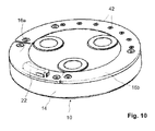
- Figure 10 illustrates the final configuration of the end cap 10 including the sensor unit 22 and the energy generating system covered by the cover plate 16b.
Abstract
Description
- The invention relates a bearing device provided with an energy harvesting means.
- The document
WO 2014/108169 A1 relates to an end cap for a bearing assembly configured to be attached to a rotatable part of the bearing. A pendulum unit is attached to the centre axis of the end cap and is adapted to oscillate between two positions under the influence of gravity such that energy can be generated by an oscillation of the pendulum unit. - Further, it is known to provide energy harvesting devices in various parts of the bearings, wherein the generator is configured to interact with a rotating target ring, encoder wheel or tone wheel such that the relative rotation of different parts of the bearing creates an oscillating current in a coil, which can be rectified for further use.
- Further, it is known from other fields of technology, e.g. from watches, to use a micro generating system that converts the human movement into electric energy. Micro generating systems comprise at least an eccentric mass, a miniaturized claw pole generator, and an energy storage, wherein a gear box may be optionally provided between the eccentric mass and the generator.
- The
document DE 10 2006 044 562 A1 discloses a further generator unit using the oscillating gravitational force for driving a pendulum to create energy for measuring tire pressure for vehicles. - The known systems for energy harvesting based on gravitational forces in bearings have a limited scope of applicability because the oscillation amplitude of the pendulum has to be limited by stops. Further, the dynamics of the pendulum strongly depends on the centrifugal force and therefore on the speed of rotation of the bearing such that it is difficult to adapt the design of the pendulum to the intended field of application.
- On the other hand, energy harvesting devices based on magnetic interaction are sensitive to external magnetic fields and the efficiency strongly depends on the precision of the gap between a rotating target ring and the yoke of a generator which is difficult to maintain in many fields of application.
- The invention seeks to overcome the drawbacks of the prior art by providing a bearing arrangement including an energy generating system which is cost saving, robust and scalable.
- The invention relates to a bearing arrangement including a rotating part and a non-rotating part, wherein the rotating part is configured to rotate relative to the non-rotating part with an essentially horizontal rotation axis.
- It is proposed that the energy generating system comprises at least one micro generator module including a housing, an eccentric mass mounted so as to be rotatable around an eccentric shaft in the housing, and a generator unit configured to generate electrical energy from the rotation of the eccentric shaft.
- The micro generator module with the separate generator housing may be easily mounted at suitable places on the rotating part of the bearing assembly, is robust and versatile. In particular, the energy generating system is modular in the sense that multiple micro generating modules may be used in a system and attached to the rotating part of the bearing if necessary.
- In a preferred embodiment of the invention, the eccentric shaft of the micro generator modules is arranged in a radial direction with regard to the axis of rotation of the bearing assembly as a whole. In other words, the eccentric shaft axis of rotation is essentially perpendicular to the bearing axis of rotation. As a consequence, the centrifugal forces generated by the rotation of the bearing do not affect the dynamics of the eccentric mass, which only depends on the gravitational force. The gravitational force oscillates as a consequence of the rotation of the rotating part when considering the local coordinate system of the rotating part of the bearing assembly. The amplitude of the gravitational force component acting on the eccentric mass is maximum if the rotation axis is horizontal. However, the invention is not limited to horizontal rotation axes and could be applied to axes deviating from the horizontal direction as well as long as the amplitude of the oscillating component of the gravity is strong enough.
- Further, it is proposed to use housings of the micro generating system which are essentially cylindrical, wherein the radially outer surface of the cylindrical housings may be optionally provided with O-rings preventing the sliding of the micro generating modules within their accommodation.
- Further, it is proposed that the generator system comprises multiple micro generator units as described above, arranged in an arc-shaped outer housing configured to be attached to the rotating part of the bearing assembly. The curvature of the arc-shaped plastic housing can be adapted to the bearing to which the system shall be applied. The modular nature of the energy generating system facilitates the adaptation to different bearing types in that only the outer housing has to be adapted to the mounting environment and to the number of micro-generating systems to be accommodated.
- Further, it is proposed that the outer housing of the energy generating system includes a circuit board with electronic devices driven by the energy generated by the micro generating system and optionally with energy storage means such as a capacitor or the like. The devices mounted on the printed circuit board may include a microprocessor, temperature sensors, pressure sensors, acceleration sensors, vibration sensors, acoustic emission sensors and/or wireless transmitters to transmit the data calculated by the microcontroller to the outside. Alternatively, the energy generating system may be provided in addition and separate from a unit for transmitting the signals to the outside.
- In the preferred embodiment of the invention, the bearing assembly is configured as a railway axle bearing and the energy generator assembly is mounted in an end cap of the axle bearing. Further details on the sensor system are disclosed e.g. in
WO 2014/154259 , which is included herein by reference. - The above embodiments of the invention as well as the appended claims and figures show multiple characterizing features of the invention in specific combinations. The skilled person will easily be able to consider further combinations or sub-combinations of these features in order to adapt the invention as defined in the claims to his specific needs.
-
- Fig. 1
- is a railway axle bearing unit provided with an end cap equipped with an energy generating system according to the invention.
- Fig. 2
- is a sectional view of the bearing unit according to
Figure 1 . - Fig. 3
- is a sectional view of a body of the end cap in
Figure 2 . - Fig. 4
- is a view of the end cap with the energy-generating system according to the invention with some cover elements removed or illustrated as transparent.
- Fig. 5
- is a sectional view of an example of a micro generator module of the energy generating system according to the invention.
- Fig. 6
- is a perspective view of a micro generator module according to
Figure 5 . - Fig. 7
- is an exploded view of an energy generating system according to the invention comprising micro generators as shown in
Figs. 5 and 6 - Fig. 8
- illustrates the assembly of the energy generating system according to the
Fig. 7 and the attachment thereof to cover plates of the bearing unit. - Fig. 9
- is an exploded view illustrating the final assembly of the energy generating system in an end cap according to the invention.
- Fig. 10
- is a perspective view of the end cap of
Fig. 9 in its final configuration. -
Figures 1 and2 show a railway axle bearing unit including anend cap 10 fixed with threebolts 12 on an axial end face of anaxle 13 so as to preload and retain abearing 5. The bearing is double-row taper roller bearing in the depicted example, comprising a non-rotatingouter ring 7 which is mounted in ahousing 20 known as a saddle adapter. The bearing further has first and secondinner rings rotational axle 13. Between theouter ring 7 and the first and secondinner rings second rows - The
end cap 10 comprises a solid metal base part and arc-shaped cover plates screws 17. - The
metal base part 14 is illustrated in a cross-sectional view inFigure 3 . An outer side of themetal base part 14 facing away from thebearing unit 5 in the assembled configuration is provided with an angular, groove-like recess 18 which is symmetric with respect to a centre of rotation of theend cap 10. Therecess 18 is delimited by ametal wall 19 of substantially constant thickness on the radially outer side and by a solid bulk body of abase part 14 on the radially inner side. - The
cover plates like recess 18 which is machined into thebase part 14 around its entire circumference andholes 12a for thebolts 12 and for the screws fixing thecover plates end cap 10. - As illustrated in
Figure 2 , the recess accommodates asensor unit 22 underneath thecover plate 16a. Thesensor unit 22 includes a micro-processor, a transmitter with an antenna part projecting through a window over thecover plate 16a, sensors and means for storing identification information and other information relating to the operation of the bearing. - The
cover plate 16b covers the energy generating system according to the invention, which supplies the energy needed by thesensor unit 22. -
Figure 4 illustrates theend cap 10 with thecover plate 16b removed. The energy generating system includes a plurality of micro-generators ormicro generator modules 24, each having aneccentric mass 26 at aneccentric shaft 28 carrying theeccentric mass 26. Theeccentric shafts 28 are aligned radially with regard to the rotation axis of the bearing in the mounted configuration of theend cap 10. - A further example of a micro generator module according to the invention is illustrated in more detail in
Figure 5 . Theeccentric shaft 28 is connected via gears forming a transmission to agenerator 30. The generator may be executed as a claw pole generator comprising a magnetic rotor and a number of claw poles. The magnetic rotor is coupled to theeccentric shaft 28, through the transmission, and generates electric current via electromagnetic induction in the known manner. Thegenerator 30 and theeccentric shaft 28 are accommodated a substantially cylindricalmicro-generator housing 32 such that the mechanical parts are protected against dust and dirt. - As the
end cap 10 rotates (about a horizontal axis), two forces act on the eccentric mass 26: centrifugal force and gravitational force. Constant rotation generates a constant centrifugal force on the eccentric mass in a constant direction (local coordinate system). This force will not excite theeccentric mass 26 andshaft 28 to rotate and generate energy, and should therefore be decoupled from the system. This is achieved in that theeccentric mass 26 andshaft 28 have an axis of rotation which is perpendicular to the bearing axis of rotation. The gravitational force is constant, but changes direction (local coordinate system). This change in direction excites the eccentric mass, causing theeccentric shaft 28 to spin and generate energy. Thus, the micro generator is arranged so as to be predominantly sensitive to gravitational force, by using the gravity force component that is perpendicular to the centripetal force. - The
micro-generator housing 32 is illustrated in a perspective view inFigure 6 . Two O-rings micro-generator housing 32 in order to avoid a slipping and play within the accommodating housing 36 (Fig. 7 ) of the micro-generator units. - The
accommodating housing 36 of the energy generating system according to the invention is illustrated in further detail inFigure 7 . Thehousing 36 has an upper part a the lower part and is substantially arc-shaped following the curvature of thegroove 18. The two parts of thehousing 36 are shaped such that themicro generator modules 24 and a printedcircuit board 38 carrying a super-capacitor 40 are stably fixed. The printedcircuit board 38 may be further provided with suitable rectifiers and control circuits for controlling the charging of the super-capacitor 40 or other energy storage means. - As illustrated in
Figure 8 , theaccommodating housing 36 is fixed to thecover plate 16b by means ofscrews 42 which further hold the two parts of thehousing 36 together. The screw holes 44 in thehousing 36 and the connectingportions 46 of thehousing 36 where the two housing parts are connected, and a hole through which an electric cable with aconnector 48 passes are securely sealed by overmoulded or fitted rubber elements, O-rings or the like. - After having fixed the generator system to the
cover plate 16b and thesensor unit 22 to thecover plate 16a and having connected aconnector 48 of the electric cable to a corresponding connector of the sensor unit, thecover plates body part 14 of theend cap 10, as illustrated inFigure 9 , by means ofscrews 50. -
Figure 10 illustrates the final configuration of theend cap 10 including thesensor unit 22 and the energy generating system covered by thecover plate 16b.
Claims (13)
- Bearing arrangement including a rotating part (8a, 8b, 13) and a non-rotating part (7, 20), wherein the rotating part is configured to rotate relative to the non-rotating part with an essentially horizontal rotation axis, the arrangement being provided with an energy generating system that is mounted in connection with the rotating part,
characterized in that the energy generating system comprises at least one micro generator module (24), wherein the micro generator module (24) includes a housing (32), an eccentric mass (26) mounted so as to be rotatable around an eccentric shaft (28) in the housing (32), and a generator unit (30) configured to generate electrical energy using the rotation of the eccentric shaft (28). - Bearing arrangement according to claim 1, characterized in that the energy generating system comprises a plurality of micro generator modules (24).
- Bearing arrangement according to claim 1 or 2, characterized in that the eccentric shaft (28) of the micro generator modules (24) has an axis of rotation which is arranged in a radial direction with regard to the axis of rotation of the bearing arrangement as a whole.
- Bearing arrangement according to one of the preceding claims, characterized in that the micro generator modules (24) are commonly arranged in an outer housing (36).
- Bearing arrangement according to claim 4, characterized in that the outer housing (36) further accommodates at least one energy storage means (40) for storing energy generated by the micro generator modules (24).
- Bearing arrangement according to one of claims 4 to 5, characterized in that the energy storage means (40) is a capacitor.
- Bearing arrangement according to one of claims 4 to 6, characterized in that the outer housing (36) further accommodates at least one electronic device for managing the storage of the energy generated by the micro generator modules (24).
- Bearing arrangement according to one of claims 4 - 7, characterized in that the energy generating system includes a connector (48) for making energy generated by the micro generator modules (24) available outside of the outer housing (36).
- Bearing arrangement according to one of claims 4 - 8, characterized in that the outer housing (36) comprises sealing means for sealing the energy generating system.
- Bearing arrangement according to one of the preceding claims, characterized in that the housings (32) of the micro generator modules (24) are essentially cylindrical.
- Bearing arrangement according to any preceding claim, further comprising an end cap (10) for exerting a preload on the bearing arrangement, characterized in that the energy generating system is arranged within the end cap.
- Railway axle bearing unit comprising a bearing arrangement according to claim 11.
- End cap (10) for use in a railway axle bearing unit according to claim 12, wherein the energy generating system is integrated in the end cap (10).
Applications Claiming Priority (1)
| Application Number | Priority Date | Filing Date | Title |
|---|---|---|---|
| GBGB1419229.8A GB201419229D0 (en) | 2014-10-29 | 2014-10-29 | Bearing device with energy harvesting means |
Publications (2)
| Publication Number | Publication Date |
|---|---|
| EP3016252A1 true EP3016252A1 (en) | 2016-05-04 |
| EP3016252B1 EP3016252B1 (en) | 2022-11-02 |
Family
ID=52103567
Family Applications (1)
| Application Number | Title | Priority Date | Filing Date |
|---|---|---|---|
| EP15186209.1A Active EP3016252B1 (en) | 2014-10-29 | 2015-09-22 | Bearing arrangement with energy harvesting means |
Country Status (4)
| Country | Link |
|---|---|
| US (1) | US10491076B2 (en) |
| EP (1) | EP3016252B1 (en) |
| CN (1) | CN105570321B (en) |
| GB (1) | GB201419229D0 (en) |
Cited By (1)
| Publication number | Priority date | Publication date | Assignee | Title |
|---|---|---|---|---|
| CN113565867A (en) * | 2021-07-28 | 2021-10-29 | 上海交通大学 | Bearing roller self-powered monitoring device for gravitational potential energy power generation |
Families Citing this family (5)
| Publication number | Priority date | Publication date | Assignee | Title |
|---|---|---|---|---|
| DE102018101062A1 (en) * | 2018-01-18 | 2019-07-18 | Schaeffler Technologies AG & Co. KG | A method for operating a warehouse with at least a first energy supply module and a second energy supply module |
| DE102018211020A1 (en) * | 2018-07-04 | 2020-01-09 | Aktiebolaget Skf | Sealed storage module |
| IT201800010664A1 (en) * | 2018-11-28 | 2020-05-28 | L C A Ballauri S R L | COVERING DEVICE FOR ONE END OF A RAILWAY AXLE, AND AXLE UNIT FITTED WITH THIS DEVICE |
| JP7272193B2 (en) * | 2019-09-10 | 2023-05-12 | 日本精工株式会社 | Power generation unit and bearing unit |
| DE102020202692A1 (en) | 2020-03-03 | 2021-09-09 | Aktiebolaget Skf | Sensor roller for a bearing that has an integrated energy harvesting device |
Citations (5)
| Publication number | Priority date | Publication date | Assignee | Title |
|---|---|---|---|---|
| US5115738A (en) * | 1986-04-25 | 1992-05-26 | Heidelberger Druckmaschinen Ag | Printing machine particularly a sheet-fed offset printing machine |
| EP1120887A2 (en) * | 2000-01-28 | 2001-08-01 | Matsushita Electric Industrial Co., Ltd. | Small and flat motor, and apparatus using the same motor |
| US20050140201A1 (en) * | 2003-12-29 | 2005-06-30 | Wen-Chang Wang | Wheel cover for automobile |
| US8564148B1 (en) * | 2011-05-11 | 2013-10-22 | John J. Novak | AC energy generator |
| WO2014154259A1 (en) * | 2013-03-27 | 2014-10-02 | Aktiebolaget Skf | Hub unit |
Family Cites Families (14)
| Publication number | Priority date | Publication date | Assignee | Title |
|---|---|---|---|---|
| GB1576619A (en) | 1976-05-13 | 1980-10-08 | Northern Eng Ind | Dc supplies |
| DE2951563A1 (en) * | 1979-12-21 | 1981-07-02 | Vorwerk & Co Interholding Gmbh, 5600 Wuppertal | BEARING FOR THE ROTOR SHAFT OF ELECTRIC MOTORS WITH BLOWING WHEEL |
| DE4119834A1 (en) * | 1991-06-12 | 1992-12-17 | Mannesmann Ag | METHOD FOR GENERATING ELECTRICAL ENERGY BY MEANS OF A GENERATOR, AND USE IN VEHICLES WITH ANTI-SLIDING SYSTEM |
| JPH11125244A (en) | 1997-10-24 | 1999-05-11 | Daido Steel Co Ltd | Overheat alarming device for axle of freight train |
| US6474832B2 (en) * | 1999-08-23 | 2002-11-05 | Wayne H. Murray | Self-regulating, axle-mounted electrical generation device |
| US6386731B1 (en) * | 2000-08-30 | 2002-05-14 | Chen-Kang Cheng | Light emitting rotating body on an automobile |
| US6749321B2 (en) * | 2002-08-28 | 2004-06-15 | Yueh-Ying Pan | Automatic power-generating device for decorative lamps |
| US20060236712A1 (en) * | 2005-04-20 | 2006-10-26 | Antonio Vazquez | Adjustable Portable A/C System |
| DE102006044562A1 (en) | 2006-09-21 | 2008-04-10 | Siemens Ag | Wheel electronics arrangement, has wheel with bearing system which is provided with movable mass, where bearing system is arranged on circular segment path that is provided on rim bearing surface of wheel |
| US7675189B2 (en) * | 2007-07-17 | 2010-03-09 | Baseload Energy, Inc. | Power generation system including multiple motors/generators |
| ITTO20080162A1 (en) * | 2008-03-04 | 2009-09-05 | Sequoia It S R L | SELF-POWERED BEARING MONITORING SYSTEM |
| DE102011082270B4 (en) | 2011-09-07 | 2020-08-13 | Schaeffler Technologies AG & Co. KG | Storage device with a power generation unit |
| DE102012202029A1 (en) * | 2012-02-10 | 2013-08-14 | Aktiebolaget Skf | Warehouse and wind turbine |
| WO2014108169A1 (en) * | 2013-01-08 | 2014-07-17 | Aktiebolaget Skf | End cap for a bearing assembly |
-
2014
- 2014-10-29 GB GBGB1419229.8A patent/GB201419229D0/en not_active Ceased
-
2015
- 2015-09-22 EP EP15186209.1A patent/EP3016252B1/en active Active
- 2015-10-15 CN CN201510666175.0A patent/CN105570321B/en active Active
- 2015-10-27 US US14/923,474 patent/US10491076B2/en active Active
Patent Citations (5)
| Publication number | Priority date | Publication date | Assignee | Title |
|---|---|---|---|---|
| US5115738A (en) * | 1986-04-25 | 1992-05-26 | Heidelberger Druckmaschinen Ag | Printing machine particularly a sheet-fed offset printing machine |
| EP1120887A2 (en) * | 2000-01-28 | 2001-08-01 | Matsushita Electric Industrial Co., Ltd. | Small and flat motor, and apparatus using the same motor |
| US20050140201A1 (en) * | 2003-12-29 | 2005-06-30 | Wen-Chang Wang | Wheel cover for automobile |
| US8564148B1 (en) * | 2011-05-11 | 2013-10-22 | John J. Novak | AC energy generator |
| WO2014154259A1 (en) * | 2013-03-27 | 2014-10-02 | Aktiebolaget Skf | Hub unit |
Cited By (2)
| Publication number | Priority date | Publication date | Assignee | Title |
|---|---|---|---|---|
| CN113565867A (en) * | 2021-07-28 | 2021-10-29 | 上海交通大学 | Bearing roller self-powered monitoring device for gravitational potential energy power generation |
| CN113565867B (en) * | 2021-07-28 | 2022-03-25 | 上海交通大学 | Bearing roller self-powered monitoring device for gravitational potential energy power generation |
Also Published As
| Publication number | Publication date |
|---|---|
| EP3016252B1 (en) | 2022-11-02 |
| GB201419229D0 (en) | 2014-12-10 |
| US20160126807A1 (en) | 2016-05-05 |
| CN105570321B (en) | 2020-06-05 |
| US10491076B2 (en) | 2019-11-26 |
| CN105570321A (en) | 2016-05-11 |
Similar Documents
| Publication | Publication Date | Title |
|---|---|---|
| EP3016252B1 (en) | Bearing arrangement with energy harvesting means | |
| CN107250586B (en) | For the sensor device of rolling bearing and the rolling bearing system with this sensor device | |
| US20180361789A1 (en) | Rolling bearing unit for drive wheel support | |
| JP2004133911A (en) | Wireless sensor system and bearing apparatus having wireless sensor | |
| US20070159352A1 (en) | Bearing assembly having built-in wireless sensor | |
| US20050017602A1 (en) | Shaft mounted energy harvesting for wireless sensor operation and data transmission | |
| CN113039141B (en) | Conveyor idler monitoring apparatus, systems, and methods | |
| WO2015032449A1 (en) | Bearing assembly including a sensor roller | |
| EP3370050A1 (en) | Wheel supporting rolling bearing unit | |
| WO2009034321A1 (en) | Electrical generator | |
| BR112017018624B1 (en) | MEASUREMENT SYSTEM AND METHOD FOR THE DETECTION OF QUANTITIES IN PLANETARY SUPPORTS OF A PLANETARY TRANSMISSION | |
| WO2014154259A1 (en) | Hub unit | |
| CN211351948U (en) | Electric actuator | |
| EP4157701B1 (en) | Pedal for bicycles with integrated generator | |
| WO2015032445A1 (en) | Sensor roller and bearing assembly | |
| JP2004127276A (en) | Wireless sensor system and bearing device with wireless sensor | |
| JP2003042151A (en) | Rolling bearing device and ring with sensor of the bearing device | |
| CN111601760A (en) | Conveyor idler monitoring apparatus, systems, and methods | |
| CN108725640A (en) | Vehicle notification device | |
| US11228227B2 (en) | Electric actuator with eccentric shaft | |
| CN106471342B (en) | Sensor device and rolling bearing comprising such a sensor device | |
| US11415177B2 (en) | Sensorized roller for a bearing having integrated energy harvesting device | |
| WO2014086410A1 (en) | Bearing power generating configuration | |
| US20210187684A1 (en) | Measuring system for monitoring a spindle | |
| JP6893843B2 (en) | Rolling bearing unit for wheel support |
Legal Events
| Date | Code | Title | Description |
|---|---|---|---|
| PUAI | Public reference made under article 153(3) epc to a published international application that has entered the european phase |
Free format text: ORIGINAL CODE: 0009012 |
|
| 17P | Request for examination filed |
Effective date: 20150922 |
|
| AK | Designated contracting states |
Kind code of ref document: A1 Designated state(s): AL AT BE BG CH CY CZ DE DK EE ES FI FR GB GR HR HU IE IS IT LI LT LU LV MC MK MT NL NO PL PT RO RS SE SI SK SM TR |
|
| AX | Request for extension of the european patent |
Extension state: BA ME |
|
| RBV | Designated contracting states (corrected) |
Designated state(s): AL AT BE BG CH CY CZ DE DK EE ES FI FR GB GR HR HU IE IS IT LI LT LU LV MC MK MT NL NO PL PT RO RS SE SI SK SM TR |
|
| STAA | Information on the status of an ep patent application or granted ep patent |
Free format text: STATUS: EXAMINATION IS IN PROGRESS |
|
| 17Q | First examination report despatched |
Effective date: 20200128 |
|
| STAA | Information on the status of an ep patent application or granted ep patent |
Free format text: STATUS: EXAMINATION IS IN PROGRESS |
|
| RAP3 | Party data changed (applicant data changed or rights of an application transferred) |
Owner name: AKTIEBOLAGET SKF |
|
| GRAP | Despatch of communication of intention to grant a patent |
Free format text: ORIGINAL CODE: EPIDOSNIGR1 |
|
| STAA | Information on the status of an ep patent application or granted ep patent |
Free format text: STATUS: GRANT OF PATENT IS INTENDED |
|
| INTG | Intention to grant announced |
Effective date: 20220518 |
|
| GRAS | Grant fee paid |
Free format text: ORIGINAL CODE: EPIDOSNIGR3 |
|
| GRAA | (expected) grant |
Free format text: ORIGINAL CODE: 0009210 |
|
| STAA | Information on the status of an ep patent application or granted ep patent |
Free format text: STATUS: THE PATENT HAS BEEN GRANTED |
|
| AK | Designated contracting states |
Kind code of ref document: B1 Designated state(s): AL AT BE BG CH CY CZ DE DK EE ES FI FR GB GR HR HU IE IS IT LI LT LU LV MC MK MT NL NO PL PT RO RS SE SI SK SM TR |
|
| REG | Reference to a national code |
Ref country code: GB Ref legal event code: FG4D |
|
| REG | Reference to a national code |
Ref country code: CH Ref legal event code: EP Ref country code: AT Ref legal event code: REF Ref document number: 1529493 Country of ref document: AT Kind code of ref document: T Effective date: 20221115 |
|
| REG | Reference to a national code |
Ref country code: DE Ref legal event code: R096 Ref document number: 602015081397 Country of ref document: DE |
|
| REG | Reference to a national code |
Ref country code: IE Ref legal event code: FG4D |
|
| REG | Reference to a national code |
Ref country code: LT Ref legal event code: MG9D |
|
| REG | Reference to a national code |
Ref country code: NL Ref legal event code: MP Effective date: 20221102 |
|
| REG | Reference to a national code |
Ref country code: AT Ref legal event code: MK05 Ref document number: 1529493 Country of ref document: AT Kind code of ref document: T Effective date: 20221102 |
|
| PG25 | Lapsed in a contracting state [announced via postgrant information from national office to epo] |
Ref country code: SE Free format text: LAPSE BECAUSE OF FAILURE TO SUBMIT A TRANSLATION OF THE DESCRIPTION OR TO PAY THE FEE WITHIN THE PRESCRIBED TIME-LIMIT Effective date: 20221102 Ref country code: PT Free format text: LAPSE BECAUSE OF FAILURE TO SUBMIT A TRANSLATION OF THE DESCRIPTION OR TO PAY THE FEE WITHIN THE PRESCRIBED TIME-LIMIT Effective date: 20230302 Ref country code: NO Free format text: LAPSE BECAUSE OF FAILURE TO SUBMIT A TRANSLATION OF THE DESCRIPTION OR TO PAY THE FEE WITHIN THE PRESCRIBED TIME-LIMIT Effective date: 20230202 Ref country code: LT Free format text: LAPSE BECAUSE OF FAILURE TO SUBMIT A TRANSLATION OF THE DESCRIPTION OR TO PAY THE FEE WITHIN THE PRESCRIBED TIME-LIMIT Effective date: 20221102 Ref country code: FI Free format text: LAPSE BECAUSE OF FAILURE TO SUBMIT A TRANSLATION OF THE DESCRIPTION OR TO PAY THE FEE WITHIN THE PRESCRIBED TIME-LIMIT Effective date: 20221102 Ref country code: ES Free format text: LAPSE BECAUSE OF FAILURE TO SUBMIT A TRANSLATION OF THE DESCRIPTION OR TO PAY THE FEE WITHIN THE PRESCRIBED TIME-LIMIT Effective date: 20221102 Ref country code: AT Free format text: LAPSE BECAUSE OF FAILURE TO SUBMIT A TRANSLATION OF THE DESCRIPTION OR TO PAY THE FEE WITHIN THE PRESCRIBED TIME-LIMIT Effective date: 20221102 |
|
| PG25 | Lapsed in a contracting state [announced via postgrant information from national office to epo] |
Ref country code: RS Free format text: LAPSE BECAUSE OF FAILURE TO SUBMIT A TRANSLATION OF THE DESCRIPTION OR TO PAY THE FEE WITHIN THE PRESCRIBED TIME-LIMIT Effective date: 20221102 Ref country code: PL Free format text: LAPSE BECAUSE OF FAILURE TO SUBMIT A TRANSLATION OF THE DESCRIPTION OR TO PAY THE FEE WITHIN THE PRESCRIBED TIME-LIMIT Effective date: 20221102 Ref country code: LV Free format text: LAPSE BECAUSE OF FAILURE TO SUBMIT A TRANSLATION OF THE DESCRIPTION OR TO PAY THE FEE WITHIN THE PRESCRIBED TIME-LIMIT Effective date: 20221102 Ref country code: IS Free format text: LAPSE BECAUSE OF FAILURE TO SUBMIT A TRANSLATION OF THE DESCRIPTION OR TO PAY THE FEE WITHIN THE PRESCRIBED TIME-LIMIT Effective date: 20230302 Ref country code: HR Free format text: LAPSE BECAUSE OF FAILURE TO SUBMIT A TRANSLATION OF THE DESCRIPTION OR TO PAY THE FEE WITHIN THE PRESCRIBED TIME-LIMIT Effective date: 20221102 Ref country code: GR Free format text: LAPSE BECAUSE OF FAILURE TO SUBMIT A TRANSLATION OF THE DESCRIPTION OR TO PAY THE FEE WITHIN THE PRESCRIBED TIME-LIMIT Effective date: 20230203 |
|
| P01 | Opt-out of the competence of the unified patent court (upc) registered |
Effective date: 20230513 |
|
| PG25 | Lapsed in a contracting state [announced via postgrant information from national office to epo] |
Ref country code: NL Free format text: LAPSE BECAUSE OF FAILURE TO SUBMIT A TRANSLATION OF THE DESCRIPTION OR TO PAY THE FEE WITHIN THE PRESCRIBED TIME-LIMIT Effective date: 20221102 |
|
| PG25 | Lapsed in a contracting state [announced via postgrant information from national office to epo] |
Ref country code: SM Free format text: LAPSE BECAUSE OF FAILURE TO SUBMIT A TRANSLATION OF THE DESCRIPTION OR TO PAY THE FEE WITHIN THE PRESCRIBED TIME-LIMIT Effective date: 20221102 Ref country code: RO Free format text: LAPSE BECAUSE OF FAILURE TO SUBMIT A TRANSLATION OF THE DESCRIPTION OR TO PAY THE FEE WITHIN THE PRESCRIBED TIME-LIMIT Effective date: 20221102 Ref country code: EE Free format text: LAPSE BECAUSE OF FAILURE TO SUBMIT A TRANSLATION OF THE DESCRIPTION OR TO PAY THE FEE WITHIN THE PRESCRIBED TIME-LIMIT Effective date: 20221102 Ref country code: DK Free format text: LAPSE BECAUSE OF FAILURE TO SUBMIT A TRANSLATION OF THE DESCRIPTION OR TO PAY THE FEE WITHIN THE PRESCRIBED TIME-LIMIT Effective date: 20221102 Ref country code: CZ Free format text: LAPSE BECAUSE OF FAILURE TO SUBMIT A TRANSLATION OF THE DESCRIPTION OR TO PAY THE FEE WITHIN THE PRESCRIBED TIME-LIMIT Effective date: 20221102 |
|
| REG | Reference to a national code |
Ref country code: DE Ref legal event code: R097 Ref document number: 602015081397 Country of ref document: DE |
|
| PG25 | Lapsed in a contracting state [announced via postgrant information from national office to epo] |
Ref country code: SK Free format text: LAPSE BECAUSE OF FAILURE TO SUBMIT A TRANSLATION OF THE DESCRIPTION OR TO PAY THE FEE WITHIN THE PRESCRIBED TIME-LIMIT Effective date: 20221102 Ref country code: AL Free format text: LAPSE BECAUSE OF FAILURE TO SUBMIT A TRANSLATION OF THE DESCRIPTION OR TO PAY THE FEE WITHIN THE PRESCRIBED TIME-LIMIT Effective date: 20221102 |
|
| PLBE | No opposition filed within time limit |
Free format text: ORIGINAL CODE: 0009261 |
|
| STAA | Information on the status of an ep patent application or granted ep patent |
Free format text: STATUS: NO OPPOSITION FILED WITHIN TIME LIMIT |
|
| 26N | No opposition filed |
Effective date: 20230803 |
|
| PG25 | Lapsed in a contracting state [announced via postgrant information from national office to epo] |
Ref country code: SI Free format text: LAPSE BECAUSE OF FAILURE TO SUBMIT A TRANSLATION OF THE DESCRIPTION OR TO PAY THE FEE WITHIN THE PRESCRIBED TIME-LIMIT Effective date: 20221102 |
|
| PGFP | Annual fee paid to national office [announced via postgrant information from national office to epo] |
Ref country code: FR Payment date: 20230926 Year of fee payment: 9 Ref country code: DE Payment date: 20230928 Year of fee payment: 9 |