EP3016233A1 - Usb charger capable of displaying electric quantity of battery rod, and electric quantity display method thereof - Google Patents
Usb charger capable of displaying electric quantity of battery rod, and electric quantity display method thereof Download PDFInfo
- Publication number
- EP3016233A1 EP3016233A1 EP13887865.7A EP13887865A EP3016233A1 EP 3016233 A1 EP3016233 A1 EP 3016233A1 EP 13887865 A EP13887865 A EP 13887865A EP 3016233 A1 EP3016233 A1 EP 3016233A1
- Authority
- EP
- European Patent Office
- Prior art keywords
- battery
- electric quantity
- charged
- charging
- quantity display
- Prior art date
- Legal status (The legal status is an assumption and is not a legal conclusion. Google has not performed a legal analysis and makes no representation as to the accuracy of the status listed.)
- Granted
Links
Images


Classifications
-
- A—HUMAN NECESSITIES
- A24—TOBACCO; CIGARS; CIGARETTES; SIMULATED SMOKING DEVICES; SMOKERS' REQUISITES
- A24F—SMOKERS' REQUISITES; MATCH BOXES; SIMULATED SMOKING DEVICES
- A24F40/00—Electrically operated smoking devices; Component parts thereof; Manufacture thereof; Maintenance or testing thereof; Charging means specially adapted therefor
- A24F40/90—Arrangements or methods specially adapted for charging batteries thereof
-
- H—ELECTRICITY
- H02—GENERATION; CONVERSION OR DISTRIBUTION OF ELECTRIC POWER
- H02J—ELECTRIC POWER NETWORKS; CIRCUIT ARRANGEMENTS OR SYSTEMS FOR SUPPLYING OR DISTRIBUTING ELECTRIC POWER; SYSTEMS FOR STORING ELECTRIC ENERGY
- H02J7/00—Circuit arrangements for charging or discharging batteries or for supplying loads from batteries
- H02J7/80—Circuit arrangements for charging or discharging batteries or for supplying loads from batteries including monitoring or indicating arrangements
- H02J7/82—Control of state of charge [SOC]
Definitions
- the invention relates to a charger for an electronic cigarette, and more particularly relates to a USB charger with electric quantity display of a charging battery and a method for electric quantity display of the charging battery in the electronic cigarette.
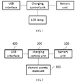
- FIG. 1 is a structure schematic of the existing technology of a USB charger which only has charging indicator without electric quantity display.
- USB chargers for batteries in electronic cigarettes only have charging state indication of "charging” or “full” displayed by monochrome or color LED lamps, some USB chargers even have not charging state indication. Therefore user does not know electric quantity of the charging battery, it will cause inconvenience to user.
- a USB charger with electric quantity display of a charging battery and method of electric quantity display are provided.
- a USB charger with electric quantity display for battery being charged comprising:
- the charging control unit is separately connected to the USB interface, the battery unit and the electric quantity display unit.
- the charging control unit controls an external power supply charging a battery in the battery unit through the USB interface, tests voltage of the battery being charged directly or indirectly, and further controls the electric quantity display unit to show updated electric quantity of the battery being charged in real time.
- the charging control unit includes: a micro controller, a charging management circuit and a sampling voltage circuit
- the battery unit includes the battery.
- the USB interface is connected to the charging management circuit separately connected to the battery and the sampling voltage circuit, the sampling voltage circuit is connected to the micro controller separately connected to the charging management circuit and the electric quantity display unit.
- the micro controller controls the charging management circuit outputting charging voltage to the battery, the sampling voltage circuit detecting the voltage of the battery being charged, and the electric quantity display unit showing electric quantity of the battery being charged.
- the charging control unit when the voltage of the battery is measured indirectly, includes: a micro controller, an adjustable output DC-DC circuit, a sampling voltage circuit and a sampling current circuit, the battery unit includes a battery and a linear charging management circuit.
- the USB interface is connected to the adjustable output DC-DC circuit separately connected to the linear charging management circuit and the sampling voltage circuit, the linear charging management circuit is connected to the battery connected to the sampling current circuit, the micro controller is separately connected to the sampling voltage circuit, the sampling current circuit, the adjustable output DC-DC unit and the electric quantity display unit.
- the micro controller controls: the sampling current circuit detecting actual charging current of the battery, the adjustable output DC-DC circuit outputting charging voltage to the battery unit to have the actual charging current of the battery equal to or slightly less than a preset constant charging current of the battery, the sampling voltage circuit detecting the charging voltage to the battery unit, and the electric quantity display unit showing electric quantity of the charging battery.
- the electric quantity display unit includes LED lamp and/or LCD screen.
- the electric quantity is a charged level of the battery being charged
- the electric quantity display unit includes at least 2 LED light indicating the charged level.
- the electric quantity includes percentage of full electric quantity of the battery being charged and spent charging time and/or surplus charging time
- the electric quantity display unit includes at least one LCD screen indicating the electric quantity.
- the charging management circuit includes a charging control chip, a first capacitor and a first resistance, the charging control chip is connected to the USB interface via the first resistor, the charging control chip is also connected to one end of the first capacitor and the positive of the battery, the other end of the first capacitor is connected to the negative of the battery.
- type of the charging control chip is VA7204, type of the micro controller is SN8P2712.
- the sampling voltage circuit includes a first divider resistor and a second divider resistor, one end of the first divider resistor is connected to the positive of the battery, the other end of first divider resistor is connected to one end of the second divider resistor and PWM2 pin of the micro controller, the other end of the second divider resistor is grounded.
- type of the micro controller is SN8P2712.
- the adjustable output DC-DC circuit includes a MOSFET, a first capacitor, a first fast recovery diode, a first resistor and a second resistor, the source of the MOSFET is connected to the negative of the first fast recovery diode, the positive of the first fast recovery diode is connected to the USB interface via the first resistance; the gate of the NOSFET is connected to pin PWM0 of the micro controller via the second resistance; the drain of the MOSFET is connected to one end of the first capacitor and the linear charging management circuit, the other end of the first capacitor is connected to the negative of the battery.
- the MOSFET is P-channel and type of the MOSFET is AO3401.
- the sampling voltage circuit includes a first divider resistor and a second divider resistor, one end of the first divider resistor is connected to one end of the first capacitor, the other end of first divider resistor is connected to one end of the second divider resistor and pin PWM2 of the micro controller, the other end of the second divider resistor is grounded.
- the sampling current circuit includes a sampling current resistor which is separately connected to pin PWM1 of the micro controller and the negative of the battery.
- the invention also discloses a method for electric quantity display of USB charger with electric quantity display of battery being charged, a charging control unit controls external power supply charging the battery in a battery unit, directly or indirectly tests voltage of the battery being charged in the battery unit, and further controls an electric quantity display unit showing electric quantity of the battery being charged.
- a micro controller controls: a charging management circuit outputting charging voltage to the battery, a sampling voltage circuit detecting voltage of the battery being charged, and the electric quantity display unit showing the electric quantity of the battery being charged.
- the micro controller controls: a sampling current circuit detecting actual charging current of the battery, an adjustable output DC-DC circuit outputting charging voltage to the battery unit to have the actual charging current of the battery equal to or slightly less than a preset constant charging current of the battery, and the sampling voltage circuit detecting the charging voltage to the battery unit.
- the voltage of the battery being charged is equal to that the charging voltage to the battery unit minus a preset difference.
- the micro controller further controls the electric quantity display unit showing electric quantity of the battery being charged.
- the electric quantity may be showed by way of columnar and/or fan-shaped and / or percentage.
- USB charger and the method of the invention, following advantages can be achieved by controlling external power supply charging the battery in battery unit, directly or indirectly testing the voltage of the charging battery and showing updated electric quantity, user can know charging level of the battery.
- FIG. 2 is a schematic block diagram of a USB charger with electric quantity display of the battery being charged according to the invention.
- the USB charger includes the battery unit 100, the charging control unit 200, the electric quantity display unit 300, and the USB interface 400, the charging control unit 200 is separately connected to the USB interface 400, the battery unit 100 and the electric quantity display 300.
- the charging control unit 200 controls external power supplies through the USB interface 400 charging a battery in battery unit 100, directly or indirectly testing a voltage of the charging battery and further controls the electric quantity display unit 300 showing updated electric quantity of the charging battery in real time.
- the electric quantity display unit 300 includes LED lamp and/or LCD screen.
- the electric quantity display unit 300 only includes LED lamp, at least 2 LED lights is configured to show a charged level of the charging battery.
- At least one LCD screen is configured to show percentage of full electric quantity of the charging battery and spent charging time and/or surplus charging time.
- the electric quantity display unit includes both LED light and LCD screen
- at least 2 LED lights is configured to show a charged level of the charging battery
- at least one LCD screen is configured to show percentage of full electric quantity of the charging battery and spent charging time and/or surplus charging time.
- the charged level may be divided into several grades, the number of grades must be an integer which equal to the number of LED lamps of the electric quantity display unit 300, each grade corresponds to a certain voltage range of the charging battery and a certain number of LED lamps. For example if the voltage of the charging battery is in N grade, so N LED lamps shall emit to show the charged lever.
- FIG. 3 is a schematic block diagram of the USB charger with electric quantity display of the battery being charged according to a first embodiment of the invention.
- a battery unit of an electronic cigarette has not charging management circuit inside, the USB charger with a charging management circuit charges a battery in the battery unit, so the charging voltage from the USB charger to the battery unit is equal to the voltage of the charging battery of the battery unit, a micro controller can get electric quantity of the charging battery from the voltage of the charging battery.
- the battery unit 100 only includes the battery 66; the charging control unit 200 includes the micro controller 20, the charging management circuit 30, and the sampling voltage circuit 40.
- the USB interface 400 is connected to the charging management circuit 30 connected to the battery 66 and the sampling voltage circuit 40, and the micro controller 20 is separately connected to the sampling voltage 40, the charging management circuit 30 and the electric quantity display unit 400.
- the micro controller 20 controls the charging management circuit 30 outputting charging voltage to the battery 66, the sampling voltage circuit 40 detecting voltage of the battery 66 being charged, the electric quantity display unit 400 showing electric quantity of the battery 66 being charged.
- the electric quantity display unit 300 is configured as LED lamps, and the electric quantity is showed by charged level.
- FIG. 4 is a schematic circuit diagram of the USB charger with electric quantity display of the battery being charged according to the first embodiment of the invention.
- the charging management circuit 30 includes a control chip U2, a first capacitor c1, a first resistor R1, type of U2 is VA7204.
- Pin 4 of the USB interface P1 is grounded, pin 1 of the USB interface P1 is connected to one end of the capacitor C4 and pin 4 (VCC of test terminal) of the control chip U2 via the first resistor R1, the other end of the capacitor C4 is grounded.
- Type of the micro controller U1 is SN8P2712, VDD pin of the micro controller U1 is connected to the negative of the fast recovery diode D1, the positive of the fast recovery diode D1 is connected to the VCC of test terminal, VDD pin of the micro controller U1 is grounded via the capacitor C3, VSS pin of the micro controller U1 is grounded, p4.0 pin of the micro controller U1 is connected to the capacitor C7, the resistor R18 and the adjustable precision shunt regulators U3, type of the U3 is CJ431.
- BAT pin of the control chip U2 is connected to one end of the first capacitor C1 and the positive of the battery 66, i.e.
- the other end of the first capacitor C1 is connected to the negative of the battery 66, i.e. OUT- terminal of the battery unit 100, INTO pin of the micro controller U1 is connected to LED pin of the control chip U2.
- the electric quantity display unit 300 includes eight blue LED lamps of L3 to L10 indicating the charged level.
- Pins of p4.1 to p4.7 of the micro controller U2 are separately connected to the negatives of the blue LED lamps of L4 to L10 separately via the resistances of R11 to R17.
- Pin Xout of the micro controller U1 is connected to the negative of the blue LED lamp L3 via the resistance R10.
- the positives of the blue LED lamps L3-L10 are all connected to the VCC of test terminal.
- Each resistance value of the R10 to R17 is same as 2K ⁇ .
- the sampling voltage circuit 40 includes the first divider resistance R4 and the second divider resistance R5.
- One end of the first divider resistance R4 is connected to the positive i.e. OUT+ of the battery unit 100, the other end of the first divider resister R4 is connected to one end of the second divider resistance R5 and pin PWM2 of the micro controller U1, the other end of the second divider resistance R5 is grounded.
- Pin PWM2 of the micro controller U1 is grounded via the capacitor C6.
- the resistance value of the first divider resistance R4 is 10 K ⁇ and is same as the resistance value of the second divider resistance R5.
- FIG. 5 is a schematic block diagram of the USB charger with electric quantity display of the battery being charged according to a second embodiment of the invention.
- the battery pole of an electric cigarette i.e. the battery unit 100
- the linear charging management circuit 77 inside, so only a fixed 5V voltage is needed to supply to the battery unit 100, but the voltage of the battery 88 being charged in the battery unit 100 can not be detected directly.
- the voltage of the batter 88 being charged can be got by following steps: controlling the adjusting output DC-DC circuit 212 outputting a charging voltage to the battery unit 100 to have the charging current through the battery 88 equal to or slight then a preset constant charging current of the battery 88, in this conditions, the voltage of the battery 88 being charged is equal to that the charging voltage to battery unit 100 minus a preset difference.
- the preset difference is 0.2 -0.5V, the preferred 0.2V. Further the electric quantity of the battery 88 is calculated.
- the battery unit 100 includes the linear charging management circuit 77 and the battery 88, they are connected electrically.
- the charging control unit 200 includes the micro controller 50, adjustable output DC-DC circuit 60, the sampling voltage circuit 80 and the sampling current circuit 70.
- the USB interface 400 is connected to the adjustable output DC-DC circuit 60 connected to the linear charging management circuit 77 and the sampling voltage circuit 80.
- the sampling voltage circuit 80 is connected to the micro controller 50 connected to the sampling current circuit 70, the electric quantity display unit 300 and the adjustable output DC-DC circuit 60.
- the linear charging management circuit 77 is connected to the battery 88 connected to the sampling current circuit 70.
- the sampling current circuit 70 is used for detecting an actual charging current to the battery 88, the micro controller 50 compares the actual charging current with the preset constant charging current of the battery 88 and then controls the adjustable output DC-DC circuit 66 outputting an adjusted charging voltage to the battery unit 100 to make that the actual charging current to the battery 88 is equal to or slight then the preset constant charging current of the battery 88.
- the sampling voltage circuit 80 detects the charging voltage to battery unit 100, and transmits it to the micro controller 50, the micro controller 50 can calculate out the voltage of the battery 88 being charged, which is equal to that the charging voltage to the battery unit 100 minus a preset difference. Further the electric quantity of the battery 88 being charged can be showed.
- the electric quantity display unit 300 is configured as LED lamps; the electric quantity of the charging battery is showed by charged level.
- the second embodiment has two modes of execution.
- FIG. 6 is a schematic circuit diagram of the USB charger with electric quantity display of the battery being charged according to a first mode of the second embodiment of the invention.
- the adjustable output DC-DC circuit 60 includes: a MOSFET Q1, a fist capacitor C1', a fist recovery diode D1', a first resistance R1' and a second resistance R2'.
- Pin 4 of the USB P1' interface is grounded, pin1 of the USB P1' interface is connected to the VCC of test terminal and one end of the capacitor C4' via the first resistance R1', and the other end of the capacitor C4' is grounded.
- Type of the micro controller U1' is SN8P2712
- pin VDD of the micro controller U1' is connected to the negative of the fast recovery diode D2 and is connected to ground via the capacitor C3'
- the positive of the fast recovery diode D2 is connected to the VCC of test terminal
- pin VSS of the micro controller U1' is grounded
- pin P4.0 of the micro controller U1' is connected to the capacitor C7', the resistance R18', and the adjustable precision shunt regulators U2' of type CJ 431.
- the source of the MOSFET Q1 is connected to the negative of the first fast recovery diode D1', and is connected to one end of the capacitor C2' and the gate of the MOSFET Q1 via the resistance R3'.
- the other end of the capacitor C2' is grounded, the positive of the first fast recovery diode D1' is connected to the VCC of test terminal;
- the gate of the MOSFET Q1 is connected to pin PWM0 of micro controller U1' via the second resistance R2';
- the drain of the MOSFET Q1 is connected to one end of the first capacitor C1' and the linear charging management circuit 77 and the OUT+ terminal of the battery unit 100, the other end of the first C1' is connected to the negative of the battery 88 and the OUT-terminal of the battery unit 100.
- the OUT+ and OUT- terminals is configured as the positive and negative of the battery unit 100 when outputting power supply to external.
- Pin PWM0 of the micro controller U1' is used to output adjustable PWM signal to control the MOSFET Q1 turn-on and turn-off, and further control charging time of the first capacitor C1' to achieve real-time adjustment of the charging voltage objective.
- Type of MOSFET Q1 is AQ3401, P channel.
- Types of all referred fast recovery diodes are same as SS14.
- the electric quantity display unit 300 includes eight blue LED lamps L3' to L10' indicating the charged level of the charging battery.
- Pins of p4.1 to p4.7 of the micro controller U1' are separately connected to the negatives of the blue LED lamps of L4' to L10' via the resistances of R11' to R17'.
- Pin PWM3 of the micro controller U1' is connected to the negative of the blue LED lamp L3 via the resistance R10'.
- the positives of the blue LED lamps L3'-L10' are all connected to the VCC of test terminal.
- Each resistance value of the R10' to R17' is same as 2K ⁇ .
- the sampling voltage circuit 80 includes the first divider resistance R4' and the second divider resistance R5', one end of the first divider resistance R4' is connected to one end of the first capacitor C1' and OUT+ terminal of the battery unit 100, the other end of the first divider resister R4' is connected to one end of the second divider resistance R5' and pin PWM2 of the micro controller U1', the other end of the second divider resistance R5 is grounded. Pin PWM2 of the micro controller U1 is grounded via the capacitor C6'.
- the resistance value of the first divider resistance R4' is 10k ⁇ as same as the second divider resistance R5'.
- the sampling current circuit 70 includes a sampling current resistance R6' with resistance value of 1 k ⁇ . One end of the sampling current resistance R6' is connected to pin PWM2 of the micro controller U1', the other end of the sampling current resistance R6' is connected to the negative of the battery 88 and the OUT- terminal of the battery unit 100. One end of the resistance R7' is connected to the OUT- terminal of the battery unit100, the other end of the resistance R7' is grounded. Pin PWM1 of the micro controller U1' is grounded via the capacitor C5.
- the adjustable output DC-DC circuit 60 includes a digital potentiometer and DC-DC output circuit.
- the digital potentiometer is used to adjust the resistance value of a feedback resistance of the DC-DC output circuit, and make the DC-DC output circuit adjust a charging voltage to the battery unit 100.
- This technology of the digital potentiometer is well known in the field, here don't do detailed.
- an electric quantity display method for a USB charger with electric quantity display of a charging battery is that: the charging control unit 200 controls external power supply charging a battery in the battery unit 100, directly or indirectly tests voltage of the battery being charged in battery unit 100, and further controls the electric quantity display unit 300 showing electric quantity of the battery being charged.
- the micro controller 20 controls: the charging management circuit 30 outputting charging voltage to the battery 66, the sampling voltage circuit 40 detecting voltage of the battery 66 being charged, and the electric quantity display unit 300 showing the electric quantity of the battery 66 being charged.
- the micro controller 50 controls: the sampling current circuit 70 detecting actual charging current of the battery 88, the adjustable output DC-DC circuit 60 outputting charging voltage to the battery unit 100 to have the actual charging current of the battery 88 equal to or slightly less than a preset constant charging current of the battery 88, and the sampling voltage circuit 80 detecting the charging voltage to the battery unit 100.
- the voltage of the battery being charged is equal to that the charging voltage to the battery unit 100 minus a preset difference.
- the micro controller further controls the electric quantity display unit 300 showing electric quantity of the battery 88 being charged.
- the electric quantity may be showed by way of columnar and/or fan-shaped and / or percentage.
- the voltage sampling frequency is one time per second.
- the electric quantity display further includes:
Landscapes
- Engineering & Computer Science (AREA)
- Power Engineering (AREA)
- Charge And Discharge Circuits For Batteries Or The Like (AREA)
- Secondary Cells (AREA)
Abstract
Description
- The invention relates to a charger for an electronic cigarette, and more particularly relates to a USB charger with electric quantity display of a charging battery and a method for electric quantity display of the charging battery in the electronic cigarette.
-
FIG. 1 is a structure schematic of the existing technology of a USB charger which only has charging indicator without electric quantity display. - Currently most of USB chargers for batteries in electronic cigarettes only have charging state indication of "charging" or "full" displayed by monochrome or color LED lamps, some USB chargers even have not charging state indication. Therefore user does not know electric quantity of the charging battery, it will cause inconvenience to user.
- For example if an user smokes when the battery in the electronic cigarette has only been charged 10% electric quantity, may be after a few inhalation of smoke, the electronic cigarette run out electricity and does no work, it causes inconvenience to the user.
- Therefore the defects of existing art need to be improved.
- To resolve the technical problem for the electric quantity of the charging battery cannot be displayed, a USB charger with electric quantity display of a charging battery and method of electric quantity display are provided.
- A USB charger with electric quantity display for battery being charged comprising:
- a USB interface;
- a battery unit;
- a charging control unit; and
- an electric quantity display unit.
- The charging control unit is separately connected to the USB interface, the battery unit and the electric quantity display unit.
- The charging control unit controls an external power supply charging a battery in the battery unit through the USB interface, tests voltage of the battery being charged directly or indirectly, and further controls the electric quantity display unit to show updated electric quantity of the battery being charged in real time.
- In the USB charger with electric quantity display for battery being charged according to the invention, when the voltage of the battery being charged is measured directly, the charging control unit includes: a micro controller, a charging management circuit and a sampling voltage circuit, the battery unit includes the battery.
- The USB interface is connected to the charging management circuit separately connected to the battery and the sampling voltage circuit, the sampling voltage circuit is connected to the micro controller separately connected to the charging management circuit and the electric quantity display unit.
- Wherein, the micro controller controls the charging management circuit outputting charging voltage to the battery, the sampling voltage circuit detecting the voltage of the battery being charged, and the electric quantity display unit showing electric quantity of the battery being charged.
- In the USB charger with electric quantity display for battery being charged according to the invention, when the voltage of the battery is measured indirectly, the charging control unit includes: a micro controller, an adjustable output DC-DC circuit, a sampling voltage circuit and a sampling current circuit, the battery unit includes a battery and a linear charging management circuit.
- The USB interface is connected to the adjustable output DC-DC circuit separately connected to the linear charging management circuit and the sampling voltage circuit, the linear charging management circuit is connected to the battery connected to the sampling current circuit, the micro controller is separately connected to the sampling voltage circuit, the sampling current circuit, the adjustable output DC-DC unit and the electric quantity display unit.
- Wherein, the micro controller controls: the sampling current circuit detecting actual charging current of the battery, the adjustable output DC-DC circuit outputting charging voltage to the battery unit to have the actual charging current of the battery equal to or slightly less than a preset constant charging current of the battery, the sampling voltage circuit detecting the charging voltage to the battery unit, and the electric quantity display unit showing electric quantity of the charging battery.
- In the USB charger with electric quantity display for battery being charged according to the invention, wherein the electric quantity display unit includes LED lamp and/or LCD screen.
- In the USB charger with electric quantity display for battery being charged according to the invention, the electric quantity is a charged level of the battery being charged, the electric quantity display unit includes at least 2 LED light indicating the charged level.
- In the USB charger with electric quantity display for battery being charged according to the invention, the electric quantity includes percentage of full electric quantity of the battery being charged and spent charging time and/or surplus charging time, the electric quantity display unit includes at least one LCD screen indicating the electric quantity.
- In the USB charger with electric quantity display for battery being charged according to the invention, the charging management circuit includes a charging control chip, a first capacitor and a first resistance, the charging control chip is connected to the USB interface via the first resistor, the charging control chip is also connected to one end of the first capacitor and the positive of the battery, the other end of the first capacitor is connected to the negative of the battery.
- In the USB charger with electric quantity display for battery being charged according to the invention, type of the charging control chip is VA7204, type of the micro controller is SN8P2712.
- In the USB charger with electric quantity display for battery being charged according to the invention, the sampling voltage circuit includes a first divider resistor and a second divider resistor, one end of the first divider resistor is connected to the positive of the battery, the other end of first divider resistor is connected to one end of the second divider resistor and PWM2 pin of the micro controller, the other end of the second divider resistor is grounded.
- In the USB charger with electric quantity display for battery being charged according to the invention, type of the micro controller is SN8P2712.
- In the USB charger with electric quantity display for battery being charged according to the invention, the adjustable output DC-DC circuit includes a MOSFET, a first capacitor, a first fast recovery diode, a first resistor and a second resistor, the source of the MOSFET is connected to the negative of the first fast recovery diode, the positive of the first fast recovery diode is connected to the USB interface via the first resistance; the gate of the NOSFET is connected to pin PWM0 of the micro controller via the second resistance; the drain of the MOSFET is connected to one end of the first capacitor and the linear charging management circuit, the other end of the first capacitor is connected to the negative of the battery. In the USB charger with electric quantity display for battery being charged according to the invention, the MOSFET is P-channel and type of the MOSFET is AO3401.
- In the USB charger with electric quantity display for battery being charged according to the invention, the sampling voltage circuit includes a first divider resistor and a second divider resistor, one end of the first divider resistor is connected to one end of the first capacitor, the other end of first divider resistor is connected to one end of the second divider resistor and pin PWM2 of the micro controller, the other end of the second divider resistor is grounded.
- In the USB charger with electric quantity display for battery being charged according to the invention, the sampling current circuit includes a sampling current resistor which is separately connected to pin PWM1 of the micro controller and the negative of the battery.
- The invention also discloses a method for electric quantity display of USB charger with electric quantity display of battery being charged, a charging control unit controls external power supply charging the battery in a battery unit, directly or indirectly tests voltage of the battery being charged in the battery unit, and further controls an electric quantity display unit showing electric quantity of the battery being charged.
- In the method for electric quantity display of USB charger with electric quantity display of battery being charged according to the invention, when directly testing a voltage of the charging battery, a micro controller controls: a charging management circuit outputting charging voltage to the battery, a sampling voltage circuit detecting voltage of the battery being charged, and the electric quantity display unit showing the electric quantity of the battery being charged.
- In the method for electric quantity display of USB charger with electric quantity display of battery being charged according to the invention, when indirectly testing the voltage of the battery being charged, the micro controller controls: a sampling current circuit detecting actual charging current of the battery, an adjustable output DC-DC circuit outputting charging voltage to the battery unit to have the actual charging current of the battery equal to or slightly less than a preset constant charging current of the battery, and the sampling voltage circuit detecting the charging voltage to the battery unit.
- The voltage of the battery being charged is equal to that the charging voltage to the battery unit minus a preset difference. The micro controller further controls the electric quantity display unit showing electric quantity of the battery being charged.
- In the method for electric quantity display of USB charger with electric quantity display of battery being charged according to the invention, the electric quantity may be showed by way of columnar and/or fan-shaped and / or percentage.
- Implementation of the USB charger and the method of the invention, following advantages can be achieved by controlling external power supply charging the battery in battery unit, directly or indirectly testing the voltage of the charging battery and showing updated electric quantity, user can know charging level of the battery.
- A more complete understanding of the invention may be derived by referring the detailed description when considered in connection with the figures, and in the accompanying drawings:
-
FIG. 1 illustrates a schematic diagram of a prior art USB charger having charging indication without electric quantity display of a battery being charged; -
FIG. 2 illustrates a schematic block diagram of a USB charger with electric quantity display of the battery being charged according to the invention; -
FIG. 3 illustrates a schematic block diagram of the USB charger with electric quantity display of the battery being charged according to a first embodiment of the invention; -
FIG. 4 illustrates a schematic circuit diagram of the USB charger with electric quantity display of the battery being charged according to the first embodiment of the invention; -
FIG. 5 illustrates a schematic block diagram of the USB charger with electric quantity display of the battery being charged according to a second embodiment of the invention; and -
FIG. 6 illustrates a schematic circuit diagram of the USB charger with electric quantity display of the battery being charged according to a first mode of the second embodiment of the invention. -
FIG. 2 is a schematic block diagram of a USB charger with electric quantity display of the battery being charged according to the invention. InFIG. 2 , the USB charger includes thebattery unit 100, thecharging control unit 200, the electricquantity display unit 300, and theUSB interface 400, thecharging control unit 200 is separately connected to theUSB interface 400, thebattery unit 100 and theelectric quantity display 300. - The
charging control unit 200 controls external power supplies through theUSB interface 400 charging a battery inbattery unit 100, directly or indirectly testing a voltage of the charging battery and further controls the electricquantity display unit 300 showing updated electric quantity of the charging battery in real time. - The electric
quantity display unit 300 includes LED lamp and/or LCD screen. - When the electric
quantity display unit 300 only includes LED lamp, at least 2 LED lights is configured to show a charged level of the charging battery. - When the electric
quantity display unit 300 only includes LCD screen, at least one LCD screen is configured to show percentage of full electric quantity of the charging battery and spent charging time and/or surplus charging time. - When the electric quantity display unit includes both LED light and LCD screen, at least 2 LED lights is configured to show a charged level of the charging battery and at least one LCD screen is configured to show percentage of full electric quantity of the charging battery and spent charging time and/or surplus charging time.
- The charged level may be divided into several grades, the number of grades must be an integer which equal to the number of LED lamps of the electric
quantity display unit 300, each grade corresponds to a certain voltage range of the charging battery and a certain number of LED lamps. For example if the voltage of the charging battery is in N grade, so N LED lamps shall emit to show the charged lever. -
FIG. 3 is a schematic block diagram of the USB charger with electric quantity display of the battery being charged according to a first embodiment of the invention. InFIG. 3 , a battery unit of an electronic cigarette has not charging management circuit inside, the USB charger with a charging management circuit charges a battery in the battery unit, so the charging voltage from the USB charger to the battery unit is equal to the voltage of the charging battery of the battery unit, a micro controller can get electric quantity of the charging battery from the voltage of the charging battery. - Specifically, in the first embodiment, the
battery unit 100 only includes thebattery 66; thecharging control unit 200 includes themicro controller 20, thecharging management circuit 30, and thesampling voltage circuit 40. - The
USB interface 400 is connected to thecharging management circuit 30 connected to thebattery 66 and thesampling voltage circuit 40, and themicro controller 20 is separately connected to thesampling voltage 40, thecharging management circuit 30 and the electricquantity display unit 400. - The
micro controller 20 controls thecharging management circuit 30 outputting charging voltage to thebattery 66, thesampling voltage circuit 40 detecting voltage of thebattery 66 being charged, the electricquantity display unit 400 showing electric quantity of thebattery 66 being charged. - The electric
quantity display unit 300 is configured as LED lamps, and the electric quantity is showed by charged level. -
FIG. 4 is a schematic circuit diagram of the USB charger with electric quantity display of the battery being charged according to the first embodiment of the invention. InFIG. 4 , thecharging management circuit 30 includes a control chip U2, a first capacitor c1, a first resistor R1, type of U2 is VA7204. -
Pin 4 of the USB interface P1 is grounded,pin 1 of the USB interface P1 is connected to one end of the capacitor C4 and pin 4 (VCC of test terminal) of the control chip U2 via the first resistor R1, the other end of the capacitor C4 is grounded. - Type of the micro controller U1 is SN8P2712, VDD pin of the micro controller U1 is connected to the negative of the fast recovery diode D1, the positive of the fast recovery diode D1 is connected to the VCC of test terminal, VDD pin of the micro controller U1 is grounded via the capacitor C3, VSS pin of the micro controller U1 is grounded, p4.0 pin of the micro controller U1 is connected to the capacitor C7, the resistor R18 and the adjustable precision shunt regulators U3, type of the U3 is CJ431. BAT pin of the control chip U2 is connected to one end of the first capacitor C1 and the positive of the
battery 66, i.e. OUT+ terminal of thebattery unit 100, the other end of the first capacitor C1 is connected to the negative of thebattery 66, i.e. OUT- terminal of thebattery unit 100, INTO pin of the micro controller U1 is connected to LED pin of the control chip U2. - The electric
quantity display unit 300 includes eight blue LED lamps of L3 to L10 indicating the charged level. - Pins of p4.1 to p4.7 of the micro controller U2 are separately connected to the negatives of the blue LED lamps of L4 to L10 separately via the resistances of R11 to R17. Pin Xout of the micro controller U1 is connected to the negative of the blue LED lamp L3 via the resistance R10. The positives of the blue LED lamps L3-L10 are all connected to the VCC of test terminal. Each resistance value of the R10 to R17 is same as 2KΩ.
- The
sampling voltage circuit 40 includes the first divider resistance R4 and the second divider resistance R5. One end of the first divider resistance R4 is connected to the positive i.e. OUT+ of thebattery unit 100, the other end of the first divider resister R4 is connected to one end of the second divider resistance R5 and pin PWM2 of the micro controller U1, the other end of the second divider resistance R5 is grounded. Pin PWM2 of the micro controller U1 is grounded via the capacitor C6. The resistance value of the first divider resistance R4 is 10 KΩ and is same as the resistance value of the second divider resistance R5. -
FIG. 5 is a schematic block diagram of the USB charger with electric quantity display of the battery being charged according to a second embodiment of the invention. InFIG. 5 , the battery pole of an electric cigarette, i.e. thebattery unit 100, has the linearcharging management circuit 77 inside, so only a fixed 5V voltage is needed to supply to thebattery unit 100, but the voltage of thebattery 88 being charged in thebattery unit 100 can not be detected directly. The voltage of thebatter 88 being charged can be got by following steps: controlling the adjusting output DC-DC circuit 212 outputting a charging voltage to thebattery unit 100 to have the charging current through thebattery 88 equal to or slight then a preset constant charging current of thebattery 88, in this conditions, the voltage of thebattery 88 being charged is equal to that the charging voltage tobattery unit 100 minus a preset difference. In this embodiment, the preset difference is 0.2 -0.5V, the preferred 0.2V. Further the electric quantity of thebattery 88 is calculated. - Specifically the
battery unit 100 includes the linearcharging management circuit 77 and thebattery 88, they are connected electrically. - The charging
control unit 200 includes themicro controller 50, adjustable output DC-DC circuit 60, the sampling voltage circuit 80 and the samplingcurrent circuit 70. - The
USB interface 400 is connected to the adjustable output DC-DC circuit 60 connected to the linearcharging management circuit 77 and the sampling voltage circuit 80. The sampling voltage circuit 80 is connected to themicro controller 50 connected to the samplingcurrent circuit 70, the electricquantity display unit 300 and the adjustable output DC-DC circuit 60. The linearcharging management circuit 77 is connected to thebattery 88 connected to the samplingcurrent circuit 70. - The sampling
current circuit 70 is used for detecting an actual charging current to thebattery 88, themicro controller 50 compares the actual charging current with the preset constant charging current of thebattery 88 and then controls the adjustable output DC-DC circuit 66 outputting an adjusted charging voltage to thebattery unit 100 to make that the actual charging current to thebattery 88 is equal to or slight then the preset constant charging current of thebattery 88. The sampling voltage circuit 80 detects the charging voltage tobattery unit 100, and transmits it to themicro controller 50, themicro controller 50 can calculate out the voltage of thebattery 88 being charged, which is equal to that the charging voltage to thebattery unit 100 minus a preset difference. Further the electric quantity of thebattery 88 being charged can be showed. - In the second embodiment, the electric
quantity display unit 300 is configured as LED lamps; the electric quantity of the charging battery is showed by charged level. - The second embodiment has two modes of execution.
-
FIG. 6 is a schematic circuit diagram of the USB charger with electric quantity display of the battery being charged according to a first mode of the second embodiment of the invention. InFIG.6 , the adjustable output DC-DC circuit 60 includes: a MOSFET Q1, a fist capacitor C1', a fist recovery diode D1', a first resistance R1' and a second resistance R2'. -
Pin 4 of the USB P1' interface is grounded, pin1 of the USB P1' interface is connected to the VCC of test terminal and one end of the capacitor C4' via the first resistance R1', and the other end of the capacitor C4' is grounded. - Type of the micro controller U1' is SN8P2712, pin VDD of the micro controller U1' is connected to the negative of the fast recovery diode D2 and is connected to ground via the capacitor C3', the positive of the fast recovery diode D2 is connected to the VCC of test terminal, pin VSS of the micro controller U1' is grounded, and pin P4.0 of the micro controller U1' is connected to the capacitor C7', the resistance R18', and the adjustable precision shunt regulators U2' of type CJ 431.
- The source of the MOSFET Q1 is connected to the negative of the first fast recovery diode D1', and is connected to one end of the capacitor C2' and the gate of the MOSFET Q1 via the resistance R3'. The other end of the capacitor C2' is grounded, the positive of the first fast recovery diode D1' is connected to the VCC of test terminal; the gate of the MOSFET Q1 is connected to pin PWM0 of micro controller U1' via the second resistance R2'; the drain of the MOSFET Q1 is connected to one end of the first capacitor C1' and the linear
charging management circuit 77 and the OUT+ terminal of thebattery unit 100, the other end of the first C1' is connected to the negative of thebattery 88 and the OUT-terminal of thebattery unit 100. The OUT+ and OUT- terminals is configured as the positive and negative of thebattery unit 100 when outputting power supply to external. - Pin PWM0 of the micro controller U1' is used to output adjustable PWM signal to control the MOSFET Q1 turn-on and turn-off, and further control charging time of the first capacitor C1' to achieve real-time adjustment of the charging voltage objective.
- Type of MOSFET Q1 is AQ3401, P channel. Types of all referred fast recovery diodes are same as SS14.
- The electric
quantity display unit 300 includes eight blue LED lamps L3' to L10' indicating the charged level of the charging battery. - Pins of p4.1 to p4.7 of the micro controller U1' are separately connected to the negatives of the blue LED lamps of L4' to L10' via the resistances of R11' to R17'. Pin PWM3 of the micro controller U1' is connected to the negative of the blue LED lamp L3 via the resistance R10'. The positives of the blue LED lamps L3'-L10' are all connected to the VCC of test terminal. Each resistance value of the R10' to R17' is same as 2KΩ.
- The sampling voltage circuit 80 includes the first divider resistance R4' and the second divider resistance R5', one end of the first divider resistance R4' is connected to one end of the first capacitor C1' and OUT+ terminal of the
battery unit 100, the other end of the first divider resister R4' is connected to one end of the second divider resistance R5' and pin PWM2 of the micro controller U1', the other end of the second divider resistance R5 is grounded. Pin PWM2 of the micro controller U1 is grounded via the capacitor C6'. The resistance value of the first divider resistance R4' is 10kΩ as same as the second divider resistance R5'. - The sampling
current circuit 70 includes a sampling current resistance R6' with resistance value of 1 kΩ. One end of the sampling current resistance R6' is connected to pin PWM2 of the micro controller U1', the other end of the sampling current resistance R6' is connected to the negative of thebattery 88 and the OUT- terminal of thebattery unit 100. One end of the resistance R7' is connected to the OUT- terminal of the battery unit100, the other end of the resistance R7' is grounded. Pin PWM1 of the micro controller U1' is grounded via the capacitor C5. - In a second mode of the second embodiment of the invention, the adjustable output DC-
DC circuit 60 includes a digital potentiometer and DC-DC output circuit. The digital potentiometer is used to adjust the resistance value of a feedback resistance of the DC-DC output circuit, and make the DC-DC output circuit adjust a charging voltage to thebattery unit 100. This technology of the digital potentiometer is well known in the field, here don't do detailed. - There is provided an electric quantity display method for a USB charger with electric quantity display of a charging battery according the invention. The method is that: the charging
control unit 200 controls external power supply charging a battery in thebattery unit 100, directly or indirectly tests voltage of the battery being charged inbattery unit 100, and further controls the electricquantity display unit 300 showing electric quantity of the battery being charged.
when directly tests voltage of the battery being charged, themicro controller 20 controls: the chargingmanagement circuit 30 outputting charging voltage to thebattery 66, thesampling voltage circuit 40 detecting voltage of thebattery 66 being charged, and the electricquantity display unit 300 showing the electric quantity of thebattery 66 being charged. - When indirectly tests voltage of the battery being charged, the
micro controller 50 controls: the samplingcurrent circuit 70 detecting actual charging current of thebattery 88, the adjustable output DC-DC circuit 60 outputting charging voltage to thebattery unit 100 to have the actual charging current of thebattery 88 equal to or slightly less than a preset constant charging current of thebattery 88, and the sampling voltage circuit 80 detecting the charging voltage to thebattery unit 100. - The voltage of the battery being charged is equal to that the charging voltage to the
battery unit 100 minus a preset difference. The micro controller further controls the electricquantity display unit 300 showing electric quantity of thebattery 88 being charged. - The electric quantity may be showed by way of columnar and/or fan-shaped and / or percentage.
- The voltage sampling frequency is one time per second.
- The electric quantity display further includes:
- The electric quantity of the battery being charged may be divided into N grades, full charged level of the battery being charged is corresponding to the N grade, a charged level of the battery being charged is corresponding to a number of lattices of the column or fan-shaped display.
- While the invention has been described by way of example and in terms of preferred embodiment, it is to be understood that the invention is not limited thereto. Those who are skill in this technology can still make various alterations and modifications without departing from the scope of the invention. Therefore, the scope of the present invention shall be defined and protected by the following claims and their equivalents.
Claims (18)
- A USB charger with electric quantity display for battery being charged, comprising:a USB interface (400);a battery unit (100); anda charging control unit (200);wherein, the USB charger further comprises an electric quantity display unit (300);the charging control unit (200) is separately connected to the USB interface (400), the battery unit (100) and the electric quantity display unit (300);the charging control unit (200) controls an external power supply charging a battery in the battery unit (100) through the USB interface (400), tests voltage of the battery being charged directly or indirectly, and further controls the electric quantity display unit (300) to show updated electric quantity of the battery being charged in real time.
- The USB charger with electric quantity display for battery being charged as claimed in claim 1, wherein the voltage of the battery being charged is tested directly, the charging control unit (200) includes: a micro controller (20), a charging management circuit (30) and a sampling voltage circuit (40), and the battery unit (100) includes the battery (66);
the USB interface (400) is connected to the charging management circuit (30) separately connected to the battery (66) and the sampling voltage circuit (40), the sampling voltage circuit (40) is connected to the micro controller (20) separately connected to the charging management circuit (30) and the electric quantity display unit (300); and
the micro controller (20) controls the charging management circuit (30) outputting charging voltage to the battery (66), the micro controller (20) further controls the sampling voltage circuit (40) detecting the voltage of the battery (66) being charged, and the electric quantity display unit (300) showing electric quantity of the battery being charged. - The USB charger with electric quantity display for battery being charged as claimed in claim 1, wherein the voltage of the battery is tested indirectly, the charging control unit (200) includes: a micro controller (50), an adjustable output DC-DC circuit (60), a sampling voltage circuit (80) and a sampling current circuit (70), the battery unit (100) includes a battery (88) and a linear charging management circuit (77);
the USB interface (400) is connected to the adjustable output DC-DC circuit (60) separately connected to the linear charging management circuit (77) and the sampling voltage circuit (80), the linear charging management circuit (77) is connected to the battery (88) connected to the sampling current circuit (70), the micro controller (50) is separately connected to the sampling voltage circuit (80), the sampling current circuit (70), the adjustable output DC-DC unit (60) and the electric quantity display unit (300); and
the micro controller (50) is configured to control charging voltage outputted to the battery unit (100) from the adjustable output DC-DC circuit (60), to control the sampling current circuit (70) to detect actual charging current of the battery (88), and further to control the adjustable output DC-DC circuit (60) to output adjusted charging voltage to the battery unit (100) in order to ensure that the actual charging current of the battery is equal to or slightly less than a preset constant charging current of the battery; the micro controller (50) further controls the sampling voltage circuit (80) to detect the adjusted charging voltage, and the electric quantity display unit (300) to show electric quantity. - The USB charger with electric quantity display for battery being charged as claimed in any one of claims 1-3, wherein the electric quantity display unit includes LED lamp and/or LCD screen.
- The USB charger with electric quantity display for battery being charged as claimed in any one of claims 1-3, wherein the electric quantity is a charged level of the battery being charged, the electric quantity display unit includes at least two LED lamps indicating the charged level.
- The USB charger with electric quantity display for battery being charged as claimed in any one of claims 1-3, wherein the electric quantity includes percentage of full electric quantity of the battery being charged and spent charging time and/or surplus charging time, the electric quantity display unit includes at least one LCD screen indicating the electric quantity.
- The USB charger with electric quantity display for battery being charged as claimed in claim 2, wherein the charging management circuit includes a charging control chip (U2), a first capacitor (C1) and a first resistance (R1), the charging control chip (U2) is connected to the USB interface (P1) via the first resistor (R1), the charging control chip (U2) is also connected to one end of the first capacitor (C1) and the positive of the battery (66), the other end of the first capacitor (C1) is connected to the negative of the battery (66).
- The USB charger with electric quantity display for battery being charged as claimed in claim 7, wherein type of the charging control chip is VA7204, type of the micro controller is SN8P2712.
- The USB charger with electric quantity display for battery being charged as claimed in claim 8, wherein the sampling voltage circuit (40) includes a first divider resistor (R4) and a second divider resistor (R5), one end of the first divider resistor (R4) is connected to the positive of the battery (66), the other end of first divider resistor (R4) is connected to one end of the second divider resistor (R5) and PWM2 pin of the micro controller (U1), the other end of the second divider resistor (R5) is grounded.
- The USB charger with electric quantity display for battery being charged as claimed in claim 3, wherein type of the micro controller (U1') is SN8P2712.
- The USB charger with electric quantity display for battery being charged as claimed in claim 10, wherein the adjustable output DC-DC circuit includes a MOSFET (Q1), a first capacitor (C1'), a first fast recovery diode (D1'), a first resistor (R1') and a second resistor (R2');
a source of the MOSFET (Q1) is connected to the negative of the first fast recovery diode (D1'), the positive of the first fast recovery diode (Q1) is connected to the USB interface (P1') via the first resistor (R1');
a gate of the NOSFET (Q1) is connected to pin PWM0 of the micro controller (U1') via the second resistance (R2');
a drain of the MOSFET (Q1) is connected to one end of the first capacitor (C1') and the linear charging management circuit (77), the other end of the first capacitor (C1') is connected to the negative of the battery (88). - The USB charger with electric quantity display for battery being charged as claimed in claim 11, wherein the MOSFET (Q1) is P-channel and type of the MOSFET (Q1) is AO3401.
- The USB charger with electric quantity display for battery being charged as claimed in claim 12, wherein the sampling voltage circuit (80) includes a first divider resistor (R4') and a second divider resistor (R5'), one end of the first divider resistor (R4') is connected to one end of the first capacitor (C1'), the other end of first divider resistor (R4') is connected to one end of the second divider resistor (R5') and pin PWM2 of the micro controller (U1'), the other end of the second divider resistor (R5') is grounded.
- The USB charger with electric quantity display for battery being charged as claimed in claim 10, wherein the sampling current circuit (70) includes a sampling current resistor (R6') which is separately connected to pin PWM1 of the micro controller (U1') and the negative of the battery (88).
- A method for electric quantity display of a USB charger with electric quantity display of battery being charged, wherein a charging control unit (200) controls external power supply to charge the battery in a battery unit (100), directly or indirectly tests voltage of the battery being charged in the battery unit (100), and further controls an electric quantity display unit (300) to show electric quantity of the battery being charged.
- The method for electric quantity display of a USB charger with electric quantity display of battery as claimed in claim 15, wherein when directly testing the voltage of the battery being charged, a micro controller controls (20) charging voltage outputted to the battery (66) from the charging management circuit (30), and further controls a sampling voltage circuit to detect the voltage of the battery (66) being charged, and controls the electric quantity display unit (300) to show the electric quantity.
- The method for electric quantity display of a USB charger with electric quantity display of battery being charged as claimed in claim 15, wherein when indirectly testing voltage of the battery being charged, the micro controller (50) controls charging voltage outputted to the battery unit (100) from an adjustable output DC-DC circuit (60), and controls a sampling current circuit (70) to detect actual charging current of the battery (88), and hence controls the adjustable output DC-DC circuit (60) to output adjusted charging voltage to the battery unit (100) in order to ensure that the actual charging current of the battery is equal to or slightly less than a preset constant charging current of the battery, and then controls the sampling voltage circuit (80) to detect the adjusted charging voltage;
the voltage of the battery (88) being charged is equal to that the charging voltage minus a preset difference; the micro controller further controls the electric quantity display unit (300) to show the electric quantity. - The method for electric quantity display of a USB charger with electric quantity display of battery being charged as claimed in claim 15, wherein the electric quantity may be showed by way of columnar and/or fan-shaped and/or percentage.
Applications Claiming Priority (1)
| Application Number | Priority Date | Filing Date | Title |
|---|---|---|---|
| PCT/CN2013/077771 WO2014205625A1 (en) | 2013-06-24 | 2013-06-24 | Usb charger capable of displaying electric quantity of battery rod, and electric quantity display method thereof |
Publications (3)
| Publication Number | Publication Date |
|---|---|
| EP3016233A1 true EP3016233A1 (en) | 2016-05-04 |
| EP3016233A4 EP3016233A4 (en) | 2017-03-22 |
| EP3016233B1 EP3016233B1 (en) | 2018-06-13 |
Family
ID=52140750
Family Applications (1)
| Application Number | Title | Priority Date | Filing Date |
|---|---|---|---|
| EP13887865.7A Not-in-force EP3016233B1 (en) | 2013-06-24 | 2013-06-24 | Usb charger capable of displaying electric quantity of battery rod, and electric quantity display method thereof |
Country Status (2)
| Country | Link |
|---|---|
| EP (1) | EP3016233B1 (en) |
| WO (1) | WO2014205625A1 (en) |
Cited By (20)
| Publication number | Priority date | Publication date | Assignee | Title |
|---|---|---|---|---|
| USD825102S1 (en) | 2016-07-28 | 2018-08-07 | Juul Labs, Inc. | Vaporizer device with cartridge |
| US10045567B2 (en) | 2013-12-23 | 2018-08-14 | Juul Labs, Inc. | Vaporization device systems and methods |
| US10045568B2 (en) | 2013-12-23 | 2018-08-14 | Juul Labs, Inc. | Vaporization device systems and methods |
| US10058130B2 (en) | 2013-12-23 | 2018-08-28 | Juul Labs, Inc. | Cartridge for use with a vaporizer device |
| US10076139B2 (en) | 2013-12-23 | 2018-09-18 | Juul Labs, Inc. | Vaporizer apparatus |
| US10104915B2 (en) | 2013-12-23 | 2018-10-23 | Juul Labs, Inc. | Securely attaching cartridges for vaporizer devices |
| US10111470B2 (en) | 2013-12-23 | 2018-10-30 | Juul Labs, Inc. | Vaporizer apparatus |
| USD836541S1 (en) | 2016-06-23 | 2018-12-25 | Pax Labs, Inc. | Charging device |
| USD842536S1 (en) | 2016-07-28 | 2019-03-05 | Juul Labs, Inc. | Vaporizer cartridge |
| US10244793B2 (en) | 2005-07-19 | 2019-04-02 | Juul Labs, Inc. | Devices for vaporization of a substance |
| US10279934B2 (en) | 2013-03-15 | 2019-05-07 | Juul Labs, Inc. | Fillable vaporizer cartridge and method of filling |
| USD849996S1 (en) | 2016-06-16 | 2019-05-28 | Pax Labs, Inc. | Vaporizer cartridge |
| USD851830S1 (en) | 2016-06-23 | 2019-06-18 | Pax Labs, Inc. | Combined vaporizer tamp and pick tool |
| US10405582B2 (en) | 2016-03-10 | 2019-09-10 | Pax Labs, Inc. | Vaporization device with lip sensing |
| US10512282B2 (en) | 2014-12-05 | 2019-12-24 | Juul Labs, Inc. | Calibrated dose control |
| USD887632S1 (en) | 2017-09-14 | 2020-06-16 | Pax Labs, Inc. | Vaporizer cartridge |
| US10865001B2 (en) | 2016-02-11 | 2020-12-15 | Juul Labs, Inc. | Fillable vaporizer cartridge and method of filling |
| USRE49196E1 (en) | 2013-10-10 | 2022-08-30 | Juul Labs, Inc. | Electronic cigarette with encoded cartridge |
| CN117256963A (en) * | 2023-10-16 | 2023-12-22 | 深圳市斯科尔科技股份有限公司 | Atomization equipment, control method and storage medium thereof |
| CN117413983A (en) * | 2023-10-16 | 2024-01-19 | 深圳市斯科尔科技股份有限公司 | Atomization device, power management method and storage medium thereof |
Families Citing this family (4)
| Publication number | Priority date | Publication date | Assignee | Title |
|---|---|---|---|---|
| CN111225574B (en) * | 2017-10-18 | 2023-07-07 | 日本烟草产业株式会社 | Battery unit, scent inhaler, charger, method of controlling battery unit, and computer-readable recording medium |
| TWI635301B (en) * | 2018-04-27 | 2018-09-11 | 宏碁股份有限公司 | Method for accurately displaying power using multiple satiety conditions and associated battery management unit |
| CN108551198A (en) * | 2018-06-27 | 2018-09-18 | 大唐终端技术有限公司 | A kind of charging indication and indicating means |
| CN111436656B (en) * | 2020-05-21 | 2024-09-03 | 深圳市五典科技有限公司 | Passive heating atomizer |
Family Cites Families (10)
| Publication number | Priority date | Publication date | Assignee | Title |
|---|---|---|---|---|
| TWI264169B (en) * | 2003-12-15 | 2006-10-11 | Qqe Technology Co Ltd | Charger with displaying charging amount of rechargeable battery |
| US7843167B2 (en) * | 2007-01-22 | 2010-11-30 | Snap-on Incorporated, Inc. | Battery charger with charge indicator |
| US8461805B2 (en) * | 2009-06-22 | 2013-06-11 | Shuang SA | Rechargeable battery pack with connecting ports for internal and external charging/output operations |
| CN201499600U (en) * | 2009-08-25 | 2010-06-09 | 陈志平 | Electronic cigarette box |
| TW201242212A (en) * | 2011-04-01 | 2012-10-16 | Samya Technology Co Ltd | Improved independent serial battery detecting charger |
| CN102255365B (en) * | 2011-08-03 | 2013-10-02 | 无锡中星微电子有限公司 | Battery charging control system and battery charging control circuit |
| US20130043827A1 (en) * | 2011-08-10 | 2013-02-21 | Nathan Daniel Weinstein | Portable power charger |
| CN202444299U (en) * | 2012-02-20 | 2012-09-19 | 郭威 | Wireless intelligent charging outer shell |
| CN102940313B (en) * | 2012-11-13 | 2015-04-01 | 卓尔悦(常州)电子科技有限公司 | Intelligent controller and intelligent control method for electronic cigarette |
| CN202998409U (en) * | 2012-11-30 | 2013-06-12 | 常州洪荒谷电子科技有限公司 | A wireless handset containing a storage unit |
-
2013
- 2013-06-24 EP EP13887865.7A patent/EP3016233B1/en not_active Not-in-force
- 2013-06-24 WO PCT/CN2013/077771 patent/WO2014205625A1/en not_active Ceased
Non-Patent Citations (1)
| Title |
|---|
| See references of WO2014205625A1 * |
Cited By (36)
| Publication number | Priority date | Publication date | Assignee | Title |
|---|---|---|---|---|
| US10244793B2 (en) | 2005-07-19 | 2019-04-02 | Juul Labs, Inc. | Devices for vaporization of a substance |
| US10638792B2 (en) | 2013-03-15 | 2020-05-05 | Juul Labs, Inc. | Securely attaching cartridges for vaporizer devices |
| US10279934B2 (en) | 2013-03-15 | 2019-05-07 | Juul Labs, Inc. | Fillable vaporizer cartridge and method of filling |
| USRE50244E1 (en) | 2013-10-10 | 2024-12-24 | Juul Labs, Inc. | Electronic cigarette with encoded cartridge |
| USRE49196E1 (en) | 2013-10-10 | 2022-08-30 | Juul Labs, Inc. | Electronic cigarette with encoded cartridge |
| US10111470B2 (en) | 2013-12-23 | 2018-10-30 | Juul Labs, Inc. | Vaporizer apparatus |
| US10058124B2 (en) | 2013-12-23 | 2018-08-28 | Juul Labs, Inc. | Vaporization device systems and methods |
| US10076139B2 (en) | 2013-12-23 | 2018-09-18 | Juul Labs, Inc. | Vaporizer apparatus |
| US10104915B2 (en) | 2013-12-23 | 2018-10-23 | Juul Labs, Inc. | Securely attaching cartridges for vaporizer devices |
| US10045567B2 (en) | 2013-12-23 | 2018-08-14 | Juul Labs, Inc. | Vaporization device systems and methods |
| US10117466B2 (en) | 2013-12-23 | 2018-11-06 | Juul Labs, Inc. | Vaporization device systems and methods |
| US10117465B2 (en) | 2013-12-23 | 2018-11-06 | Juul Labs, Inc. | Vaporization device systems and methods |
| US10159282B2 (en) | 2013-12-23 | 2018-12-25 | Juul Labs, Inc. | Cartridge for use with a vaporizer device |
| US10070669B2 (en) | 2013-12-23 | 2018-09-11 | Juul Labs, Inc. | Cartridge for use with a vaporizer device |
| US10201190B2 (en) | 2013-12-23 | 2019-02-12 | Juul Labs, Inc. | Cartridge for use with a vaporizer device |
| US11752283B2 (en) | 2013-12-23 | 2023-09-12 | Juul Labs, Inc. | Vaporization device systems and methods |
| US10912331B2 (en) | 2013-12-23 | 2021-02-09 | Juul Labs, Inc. | Vaporization device systems and methods |
| US10264823B2 (en) | 2013-12-23 | 2019-04-23 | Juul Labs, Inc. | Vaporization device systems and methods |
| US10058130B2 (en) | 2013-12-23 | 2018-08-28 | Juul Labs, Inc. | Cartridge for use with a vaporizer device |
| US10701975B2 (en) | 2013-12-23 | 2020-07-07 | Juul Labs, Inc. | Vaporization device systems and methods |
| US10045568B2 (en) | 2013-12-23 | 2018-08-14 | Juul Labs, Inc. | Vaporization device systems and methods |
| US10667560B2 (en) | 2013-12-23 | 2020-06-02 | Juul Labs, Inc. | Vaporizer apparatus |
| US10058129B2 (en) | 2013-12-23 | 2018-08-28 | Juul Labs, Inc. | Vaporization device systems and methods |
| US10512282B2 (en) | 2014-12-05 | 2019-12-24 | Juul Labs, Inc. | Calibrated dose control |
| US10865001B2 (en) | 2016-02-11 | 2020-12-15 | Juul Labs, Inc. | Fillable vaporizer cartridge and method of filling |
| US10405582B2 (en) | 2016-03-10 | 2019-09-10 | Pax Labs, Inc. | Vaporization device with lip sensing |
| USD929036S1 (en) | 2016-06-16 | 2021-08-24 | Pax Labs, Inc. | Vaporizer cartridge and device assembly |
| USD849996S1 (en) | 2016-06-16 | 2019-05-28 | Pax Labs, Inc. | Vaporizer cartridge |
| USD913583S1 (en) | 2016-06-16 | 2021-03-16 | Pax Labs, Inc. | Vaporizer device |
| USD836541S1 (en) | 2016-06-23 | 2018-12-25 | Pax Labs, Inc. | Charging device |
| USD851830S1 (en) | 2016-06-23 | 2019-06-18 | Pax Labs, Inc. | Combined vaporizer tamp and pick tool |
| USD842536S1 (en) | 2016-07-28 | 2019-03-05 | Juul Labs, Inc. | Vaporizer cartridge |
| USD825102S1 (en) | 2016-07-28 | 2018-08-07 | Juul Labs, Inc. | Vaporizer device with cartridge |
| USD887632S1 (en) | 2017-09-14 | 2020-06-16 | Pax Labs, Inc. | Vaporizer cartridge |
| CN117256963A (en) * | 2023-10-16 | 2023-12-22 | 深圳市斯科尔科技股份有限公司 | Atomization equipment, control method and storage medium thereof |
| CN117413983A (en) * | 2023-10-16 | 2024-01-19 | 深圳市斯科尔科技股份有限公司 | Atomization device, power management method and storage medium thereof |
Also Published As
| Publication number | Publication date |
|---|---|
| WO2014205625A1 (en) | 2014-12-31 |
| EP3016233A4 (en) | 2017-03-22 |
| EP3016233B1 (en) | 2018-06-13 |
Similar Documents
| Publication | Publication Date | Title |
|---|---|---|
| EP3016233B1 (en) | Usb charger capable of displaying electric quantity of battery rod, and electric quantity display method thereof | |
| US9240695B2 (en) | USB charger with electric power display and a method for electric power display | |
| US9465081B2 (en) | Battery power detecting device and method | |
| US12068460B2 (en) | Battery with a voltage regulation device | |
| US9167853B2 (en) | USB charger for electronic cigarettes | |
| US20160226286A1 (en) | Electronic cigarette case and method for detecting battery rod insertion into or removal from electronic cigarette case | |
| EP2725681A2 (en) | Intelligent charge-discharge controller for battery and electronic device having same | |
| US20150015187A1 (en) | Control circuit and method for electronic cigarette box | |
| TWI256161B (en) | Detecting method and detecting apparatus for detecting internal of rechargeable battery, rechargeable battery pack having said detecting apparatus therein, apparatus having said detecting apparatus therein, program in which said detecting method is ... | |
| US20150043117A1 (en) | Charger with over-voltage and over-current protection and method for using the same | |
| US20130307572A1 (en) | Battery simulation circuit | |
| CN103475054B (en) | A kind of lithium battery charger of Based Intelligent Control and charge control method | |
| CN102540088A (en) | Battery monitoring device and battery monitoring method | |
| CN102055033A (en) | Simulation device for battery pack | |
| CN201750179U (en) | A high-precision charger voltage detection circuit | |
| CN211348477U (en) | Lithium battery protection board detection device | |
| CN208142879U (en) | A charging control circuit and charging device | |
| CN208421054U (en) | Voltage detecting circuit and household electrical appliance | |
| CN203056645U (en) | Intelligent control circuit for charger | |
| CN115719993B (en) | Charging circuit, power supply device, charged device, charging system and chip | |
| CN205081518U (en) | Low noise biasing ware | |
| CN202205862U (en) | Simulating device of battery pack | |
| CN104062515A (en) | Lithium ion battery protective plate tester applied to automobile starting | |
| CN221597478U (en) | Lithium battery intelligent balance charging control circuit | |
| CN206211503U (en) | A kind of overcharge protection circuit |
Legal Events
| Date | Code | Title | Description |
|---|---|---|---|
| PUAI | Public reference made under article 153(3) epc to a published international application that has entered the european phase |
Free format text: ORIGINAL CODE: 0009012 |
|
| 17P | Request for examination filed |
Effective date: 20160121 |
|
| AK | Designated contracting states |
Kind code of ref document: A1 Designated state(s): AL AT BE BG CH CY CZ DE DK EE ES FI FR GB GR HR HU IE IS IT LI LT LU LV MC MK MT NL NO PL PT RO RS SE SI SK SM TR |
|
| AX | Request for extension of the european patent |
Extension state: BA ME |
|
| DAX | Request for extension of the european patent (deleted) | ||
| A4 | Supplementary search report drawn up and despatched |
Effective date: 20170217 |
|
| RIC1 | Information provided on ipc code assigned before grant |
Ipc: A24F 47/00 20060101ALI20170213BHEP Ipc: H02J 7/00 20060101AFI20170213BHEP |
|
| GRAP | Despatch of communication of intention to grant a patent |
Free format text: ORIGINAL CODE: EPIDOSNIGR1 |
|
| INTG | Intention to grant announced |
Effective date: 20180109 |
|
| RIN1 | Information on inventor provided before grant (corrected) |
Inventor name: XIANG, ZHIYONG |
|
| GRAS | Grant fee paid |
Free format text: ORIGINAL CODE: EPIDOSNIGR3 |
|
| GRAA | (expected) grant |
Free format text: ORIGINAL CODE: 0009210 |
|
| RIN1 | Information on inventor provided before grant (corrected) |
Inventor name: XIANG, ZHIYONG |
|
| AK | Designated contracting states |
Kind code of ref document: B1 Designated state(s): AL AT BE BG CH CY CZ DE DK EE ES FI FR GB GR HR HU IE IS IT LI LT LU LV MC MK MT NL NO PL PT RO RS SE SI SK SM TR |
|
| RAP1 | Party data changed (applicant data changed or rights of an application transferred) |
Owner name: HUIZHOU KIMREE TECHNOLOGY CO., LTD. SHENZHEN BRANC |
|
| REG | Reference to a national code |
Ref country code: GB Ref legal event code: FG4D |
|
| REG | Reference to a national code |
Ref country code: CH Ref legal event code: EP Ref country code: AT Ref legal event code: REF Ref document number: 1009476 Country of ref document: AT Kind code of ref document: T Effective date: 20180615 |
|
| REG | Reference to a national code |
Ref country code: IE Ref legal event code: FG4D |
|
| REG | Reference to a national code |
Ref country code: DE Ref legal event code: R096 Ref document number: 602013039071 Country of ref document: DE |
|
| REG | Reference to a national code |
Ref country code: NL Ref legal event code: MP Effective date: 20180613 |
|
| REG | Reference to a national code |
Ref country code: LT Ref legal event code: MG4D |
|
| PG25 | Lapsed in a contracting state [announced via postgrant information from national office to epo] |
Ref country code: LT Free format text: LAPSE BECAUSE OF FAILURE TO SUBMIT A TRANSLATION OF THE DESCRIPTION OR TO PAY THE FEE WITHIN THE PRESCRIBED TIME-LIMIT Effective date: 20180613 Ref country code: CY Free format text: LAPSE BECAUSE OF FAILURE TO SUBMIT A TRANSLATION OF THE DESCRIPTION OR TO PAY THE FEE WITHIN THE PRESCRIBED TIME-LIMIT Effective date: 20180613 Ref country code: SE Free format text: LAPSE BECAUSE OF FAILURE TO SUBMIT A TRANSLATION OF THE DESCRIPTION OR TO PAY THE FEE WITHIN THE PRESCRIBED TIME-LIMIT Effective date: 20180613 Ref country code: BG Free format text: LAPSE BECAUSE OF FAILURE TO SUBMIT A TRANSLATION OF THE DESCRIPTION OR TO PAY THE FEE WITHIN THE PRESCRIBED TIME-LIMIT Effective date: 20180913 Ref country code: NO Free format text: LAPSE BECAUSE OF FAILURE TO SUBMIT A TRANSLATION OF THE DESCRIPTION OR TO PAY THE FEE WITHIN THE PRESCRIBED TIME-LIMIT Effective date: 20180913 Ref country code: FI Free format text: LAPSE BECAUSE OF FAILURE TO SUBMIT A TRANSLATION OF THE DESCRIPTION OR TO PAY THE FEE WITHIN THE PRESCRIBED TIME-LIMIT Effective date: 20180613 Ref country code: ES Free format text: LAPSE BECAUSE OF FAILURE TO SUBMIT A TRANSLATION OF THE DESCRIPTION OR TO PAY THE FEE WITHIN THE PRESCRIBED TIME-LIMIT Effective date: 20180613 |
|
| PG25 | Lapsed in a contracting state [announced via postgrant information from national office to epo] |
Ref country code: HR Free format text: LAPSE BECAUSE OF FAILURE TO SUBMIT A TRANSLATION OF THE DESCRIPTION OR TO PAY THE FEE WITHIN THE PRESCRIBED TIME-LIMIT Effective date: 20180613 Ref country code: GR Free format text: LAPSE BECAUSE OF FAILURE TO SUBMIT A TRANSLATION OF THE DESCRIPTION OR TO PAY THE FEE WITHIN THE PRESCRIBED TIME-LIMIT Effective date: 20180914 Ref country code: LV Free format text: LAPSE BECAUSE OF FAILURE TO SUBMIT A TRANSLATION OF THE DESCRIPTION OR TO PAY THE FEE WITHIN THE PRESCRIBED TIME-LIMIT Effective date: 20180613 Ref country code: RS Free format text: LAPSE BECAUSE OF FAILURE TO SUBMIT A TRANSLATION OF THE DESCRIPTION OR TO PAY THE FEE WITHIN THE PRESCRIBED TIME-LIMIT Effective date: 20180613 |
|
| REG | Reference to a national code |
Ref country code: AT Ref legal event code: MK05 Ref document number: 1009476 Country of ref document: AT Kind code of ref document: T Effective date: 20180613 |
|
| PG25 | Lapsed in a contracting state [announced via postgrant information from national office to epo] |
Ref country code: NL Free format text: LAPSE BECAUSE OF FAILURE TO SUBMIT A TRANSLATION OF THE DESCRIPTION OR TO PAY THE FEE WITHIN THE PRESCRIBED TIME-LIMIT Effective date: 20180613 |
|
| REG | Reference to a national code |
Ref country code: DE Ref legal event code: R119 Ref document number: 602013039071 Country of ref document: DE |
|
| PG25 | Lapsed in a contracting state [announced via postgrant information from national office to epo] |
Ref country code: AT Free format text: LAPSE BECAUSE OF FAILURE TO SUBMIT A TRANSLATION OF THE DESCRIPTION OR TO PAY THE FEE WITHIN THE PRESCRIBED TIME-LIMIT Effective date: 20180613 Ref country code: EE Free format text: LAPSE BECAUSE OF FAILURE TO SUBMIT A TRANSLATION OF THE DESCRIPTION OR TO PAY THE FEE WITHIN THE PRESCRIBED TIME-LIMIT Effective date: 20180613 Ref country code: IS Free format text: LAPSE BECAUSE OF FAILURE TO SUBMIT A TRANSLATION OF THE DESCRIPTION OR TO PAY THE FEE WITHIN THE PRESCRIBED TIME-LIMIT Effective date: 20181013 Ref country code: SK Free format text: LAPSE BECAUSE OF FAILURE TO SUBMIT A TRANSLATION OF THE DESCRIPTION OR TO PAY THE FEE WITHIN THE PRESCRIBED TIME-LIMIT Effective date: 20180613 Ref country code: RO Free format text: LAPSE BECAUSE OF FAILURE TO SUBMIT A TRANSLATION OF THE DESCRIPTION OR TO PAY THE FEE WITHIN THE PRESCRIBED TIME-LIMIT Effective date: 20180613 Ref country code: CZ Free format text: LAPSE BECAUSE OF FAILURE TO SUBMIT A TRANSLATION OF THE DESCRIPTION OR TO PAY THE FEE WITHIN THE PRESCRIBED TIME-LIMIT Effective date: 20180613 Ref country code: PL Free format text: LAPSE BECAUSE OF FAILURE TO SUBMIT A TRANSLATION OF THE DESCRIPTION OR TO PAY THE FEE WITHIN THE PRESCRIBED TIME-LIMIT Effective date: 20180613 |
|
| REG | Reference to a national code |
Ref country code: CH Ref legal event code: PL |
|
| PG25 | Lapsed in a contracting state [announced via postgrant information from national office to epo] |
Ref country code: SM Free format text: LAPSE BECAUSE OF FAILURE TO SUBMIT A TRANSLATION OF THE DESCRIPTION OR TO PAY THE FEE WITHIN THE PRESCRIBED TIME-LIMIT Effective date: 20180613 Ref country code: IT Free format text: LAPSE BECAUSE OF FAILURE TO SUBMIT A TRANSLATION OF THE DESCRIPTION OR TO PAY THE FEE WITHIN THE PRESCRIBED TIME-LIMIT Effective date: 20180613 |
|
| REG | Reference to a national code |
Ref country code: BE Ref legal event code: MM Effective date: 20180630 |
|
| REG | Reference to a national code |
Ref country code: IE Ref legal event code: MM4A |
|
| PG25 | Lapsed in a contracting state [announced via postgrant information from national office to epo] |
Ref country code: LU Free format text: LAPSE BECAUSE OF NON-PAYMENT OF DUE FEES Effective date: 20180624 Ref country code: MC Free format text: LAPSE BECAUSE OF FAILURE TO SUBMIT A TRANSLATION OF THE DESCRIPTION OR TO PAY THE FEE WITHIN THE PRESCRIBED TIME-LIMIT Effective date: 20180613 |
|
| PLBE | No opposition filed within time limit |
Free format text: ORIGINAL CODE: 0009261 |
|
| STAA | Information on the status of an ep patent application or granted ep patent |
Free format text: STATUS: NO OPPOSITION FILED WITHIN TIME LIMIT |
|
| PG25 | Lapsed in a contracting state [announced via postgrant information from national office to epo] |
Ref country code: CH Free format text: LAPSE BECAUSE OF NON-PAYMENT OF DUE FEES Effective date: 20180630 Ref country code: DE Free format text: LAPSE BECAUSE OF NON-PAYMENT OF DUE FEES Effective date: 20190101 Ref country code: LI Free format text: LAPSE BECAUSE OF NON-PAYMENT OF DUE FEES Effective date: 20180630 Ref country code: IE Free format text: LAPSE BECAUSE OF NON-PAYMENT OF DUE FEES Effective date: 20180624 |
|
| 26N | No opposition filed |
Effective date: 20190314 |
|
| GBPC | Gb: european patent ceased through non-payment of renewal fee |
Effective date: 20180913 |
|
| PG25 | Lapsed in a contracting state [announced via postgrant information from national office to epo] |
Ref country code: SI Free format text: LAPSE BECAUSE OF FAILURE TO SUBMIT A TRANSLATION OF THE DESCRIPTION OR TO PAY THE FEE WITHIN THE PRESCRIBED TIME-LIMIT Effective date: 20180613 Ref country code: BE Free format text: LAPSE BECAUSE OF NON-PAYMENT OF DUE FEES Effective date: 20180630 Ref country code: DK Free format text: LAPSE BECAUSE OF FAILURE TO SUBMIT A TRANSLATION OF THE DESCRIPTION OR TO PAY THE FEE WITHIN THE PRESCRIBED TIME-LIMIT Effective date: 20180613 |
|
| PG25 | Lapsed in a contracting state [announced via postgrant information from national office to epo] |
Ref country code: FR Free format text: LAPSE BECAUSE OF NON-PAYMENT OF DUE FEES Effective date: 20180813 |
|
| PG25 | Lapsed in a contracting state [announced via postgrant information from national office to epo] |
Ref country code: GB Free format text: LAPSE BECAUSE OF NON-PAYMENT OF DUE FEES Effective date: 20180913 |
|
| PG25 | Lapsed in a contracting state [announced via postgrant information from national office to epo] |
Ref country code: AL Free format text: LAPSE BECAUSE OF FAILURE TO SUBMIT A TRANSLATION OF THE DESCRIPTION OR TO PAY THE FEE WITHIN THE PRESCRIBED TIME-LIMIT Effective date: 20180613 |
|
| PG25 | Lapsed in a contracting state [announced via postgrant information from national office to epo] |
Ref country code: MT Free format text: LAPSE BECAUSE OF NON-PAYMENT OF DUE FEES Effective date: 20180624 |
|
| PG25 | Lapsed in a contracting state [announced via postgrant information from national office to epo] |
Ref country code: TR Free format text: LAPSE BECAUSE OF FAILURE TO SUBMIT A TRANSLATION OF THE DESCRIPTION OR TO PAY THE FEE WITHIN THE PRESCRIBED TIME-LIMIT Effective date: 20180613 |
|
| PG25 | Lapsed in a contracting state [announced via postgrant information from national office to epo] |
Ref country code: PT Free format text: LAPSE BECAUSE OF FAILURE TO SUBMIT A TRANSLATION OF THE DESCRIPTION OR TO PAY THE FEE WITHIN THE PRESCRIBED TIME-LIMIT Effective date: 20180613 |
|
| PG25 | Lapsed in a contracting state [announced via postgrant information from national office to epo] |
Ref country code: MK Free format text: LAPSE BECAUSE OF NON-PAYMENT OF DUE FEES Effective date: 20180613 Ref country code: HU Free format text: LAPSE BECAUSE OF FAILURE TO SUBMIT A TRANSLATION OF THE DESCRIPTION OR TO PAY THE FEE WITHIN THE PRESCRIBED TIME-LIMIT; INVALID AB INITIO Effective date: 20130624 |