EP3015939A1 - Remote control device - Google Patents
Remote control device Download PDFInfo
- Publication number
- EP3015939A1 EP3015939A1 EP14818709.9A EP14818709A EP3015939A1 EP 3015939 A1 EP3015939 A1 EP 3015939A1 EP 14818709 A EP14818709 A EP 14818709A EP 3015939 A1 EP3015939 A1 EP 3015939A1
- Authority
- EP
- European Patent Office
- Prior art keywords
- speed
- helicopter
- instruction section
- range
- signal
- Prior art date
- Legal status (The legal status is an assumption and is not a legal conclusion. Google has not performed a legal analysis and makes no representation as to the accuracy of the status listed.)
- Withdrawn
Links
- 230000008859 change Effects 0.000 claims abstract description 133
- 230000001133 acceleration Effects 0.000 claims description 9
- 238000000034 method Methods 0.000 description 27
- 230000008569 process Effects 0.000 description 24
- 230000005540 biological transmission Effects 0.000 description 4
- XLYOFNOQVPJJNP-UHFFFAOYSA-N water Substances O XLYOFNOQVPJJNP-UHFFFAOYSA-N 0.000 description 4
- 230000007935 neutral effect Effects 0.000 description 3
- 239000003905 agrochemical Substances 0.000 description 2
- 230000006870 function Effects 0.000 description 2
- 230000007704 transition Effects 0.000 description 2
- 230000006399 behavior Effects 0.000 description 1
- 239000000470 constituent Substances 0.000 description 1
- 238000007796 conventional method Methods 0.000 description 1
- 230000003247 decreasing effect Effects 0.000 description 1
- 238000001514 detection method Methods 0.000 description 1
- 238000010586 diagram Methods 0.000 description 1
- 230000007274 generation of a signal involved in cell-cell signaling Effects 0.000 description 1
- 238000005507 spraying Methods 0.000 description 1
Images



Classifications
-
- A—HUMAN NECESSITIES
- A63—SPORTS; GAMES; AMUSEMENTS
- A63H—TOYS, e.g. TOPS, DOLLS, HOOPS OR BUILDING BLOCKS
- A63H27/00—Toy aircraft; Other flying toys
- A63H27/12—Helicopters ; Flying tops
-
- G—PHYSICS
- G05—CONTROLLING; REGULATING
- G05D—SYSTEMS FOR CONTROLLING OR REGULATING NON-ELECTRIC VARIABLES
- G05D13/00—Control of linear speed; Control of angular speed; Control of acceleration or deceleration, e.g. of a prime mover
- G05D13/02—Details
- G05D13/04—Details providing for emergency tripping of an engine in case of exceeding maximum speed
-
- A—HUMAN NECESSITIES
- A63—SPORTS; GAMES; AMUSEMENTS
- A63H—TOYS, e.g. TOPS, DOLLS, HOOPS OR BUILDING BLOCKS
- A63H30/00—Remote-control arrangements specially adapted for toys, e.g. for toy vehicles
- A63H30/02—Electrical arrangements
- A63H30/04—Electrical arrangements using wireless transmission
-
- B—PERFORMING OPERATIONS; TRANSPORTING
- B64—AIRCRAFT; AVIATION; COSMONAUTICS
- B64U—UNMANNED AERIAL VEHICLES [UAV]; EQUIPMENT THEREFOR
- B64U10/00—Type of UAV
- B64U10/10—Rotorcrafts
- B64U10/17—Helicopters
-
- G—PHYSICS
- G05—CONTROLLING; REGULATING
- G05D—SYSTEMS FOR CONTROLLING OR REGULATING NON-ELECTRIC VARIABLES
- G05D1/00—Control of position, course, altitude or attitude of land, water, air or space vehicles, e.g. using automatic pilots
- G05D1/0011—Control of position, course, altitude or attitude of land, water, air or space vehicles, e.g. using automatic pilots associated with a remote control arrangement
- G05D1/0016—Control of position, course, altitude or attitude of land, water, air or space vehicles, e.g. using automatic pilots associated with a remote control arrangement characterised by the operator's input device
-
- G—PHYSICS
- G05—CONTROLLING; REGULATING
- G05D—SYSTEMS FOR CONTROLLING OR REGULATING NON-ELECTRIC VARIABLES
- G05D1/00—Control of position, course, altitude or attitude of land, water, air or space vehicles, e.g. using automatic pilots
- G05D1/0011—Control of position, course, altitude or attitude of land, water, air or space vehicles, e.g. using automatic pilots associated with a remote control arrangement
- G05D1/0033—Control of position, course, altitude or attitude of land, water, air or space vehicles, e.g. using automatic pilots associated with a remote control arrangement by having the operator tracking the vehicle either by direct line of sight or via one or more cameras located remotely from the vehicle
-
- G—PHYSICS
- G05—CONTROLLING; REGULATING
- G05D—SYSTEMS FOR CONTROLLING OR REGULATING NON-ELECTRIC VARIABLES
- G05D1/00—Control of position, course, altitude or attitude of land, water, air or space vehicles, e.g. using automatic pilots
- G05D1/02—Control of position or course in two dimensions
- G05D1/0202—Control of position or course in two dimensions specially adapted to aircraft
-
- B—PERFORMING OPERATIONS; TRANSPORTING
- B64—AIRCRAFT; AVIATION; COSMONAUTICS
- B64U—UNMANNED AERIAL VEHICLES [UAV]; EQUIPMENT THEREFOR
- B64U2201/00—UAVs characterised by their flight controls
- B64U2201/20—Remote controls
Definitions
- the present invention relates to remote control devices, and more specifically to a remote control device which is used to control transportation equipment such as an unmanned helicopter.
- Patent Literature 1 An example of conventional techniques in this kind is disclosed in Patent Literature 1.
- Patent Literature 1 discloses an operation assisting device for an unmanned radio-controlled helicopter.
- the operation assisting device is interposed between a receiver and servo motors in a conventional unmanned radio-controlled helicopter, and is composed of a microcomputer, a PWM signal reading circuit, a PWM signal generation circuit, a PWM signal switching circuit, and various sensors.
- hovering is performed when the operator's operation is in neutral, and when there is an operation by the operator, the servo motors are controlled accordingly or an amount of the operation is interpreted as a target value and the control is performed to follow the value.
- Patent Literature 1 JP-A 2009-96369
- the above-described operation assisting device is difficult for an operator to operate and requires a high level of skills. In particular, under external conditions such as strong winds, it becomes even more difficult to maintain a constant flying speed of the helicopter stably.
- a primary object of the present invention is to provide a remote control device capable of easily maintaining transportation equipment at a desired speed.
- a remote control device of transportation equipment which includes an instruction section which instructs a speed of the transportation equipment; and a controller which controls the speed of the transportation equipment based on the instruction from the instruction section.
- the instruction section is capable of selectively outputting one of a speed change signal for changing the speed of the transportation equipment and a speed determination signal for determining the speed of the transportation equipment; and the controller determines whether the speed of the transportation equipment should be maintained or brought to zero based on a result of comparison between speed information of the transportation equipment and a threshold value, when the output from the instruction section is changed from the speed change signal to the speed determination signal.
- the operator outputs a speed change signal from the instruction section, whereupon the transportation equipment accelerates or decelerates. Then, as the operator changes the output from the instruction section, from the speed change signal to a speed determination signal, a comparison is made between speed information of the transportation equipment at this specific time point and the threshold value. If an absolute value of the speed information of the transportation equipment is not smaller than the threshold value (or greater than the threshold value), the speed of the transportation equipment is maintained. On the other hand, if the absolute value of the speed information of the transportation equipment is smaller than the threshold value (or not greater than the threshold value), the speed of the transportation equipment is brought to zero, and the transportation equipment is stopped.
- the absolute value of the speed information of the transportation equipment is not smaller than the threshold value (or greater than the threshold value)
- an instruction section in a remote control device is operated to change a tilt angle of a nose of the unmanned helicopter in an up-down direction for varying the speed of the unmanned helicopter.
- the speed of the unmanned helicopter can be controlled in two methods, i.e., so-called “attitude control” and so-called “speed control”.
- attitude control a tilt angle of the nose in an up-down direction is changed in accordance with an amount of operation made to the instruction section, whereby the speed of the unmanned helicopter is varied.
- a tilt angle of the nose in an up-down direction is varied so as to attain a target speed corresponding to an amount of operation made to the instruction section, and once the target speed is attained, this speed becomes a target speed to maintain.
- Each operator uses one of the "attitude control” and the “speed control” as his/her main method to remotely control an unmanned helicopter depending on his/her preference, an amount of experience, etc.
- the transportation equipment is provided by an unmanned helicopter.
- the operator when outputting the speed change signal from the instruction section, the operator can easily keep the unmanned helicopter at a desired speed by simply outputting the speed determination signal from the instruction section in whichever control of the "attitude control" and the "speed control" he/she selects. Therefore, the present invention is suitable for whichever type of operators, i.e., those who prefer the "attitude control" and those who prefer the "speed control”.
- the remote control device includes a switch or the like for switching between the "attitude control” and the "speed control” aside from the instruction section for instruction on the speed.
- a switch or the like for switching between the "attitude control” and the "speed control” aside from the instruction section for instruction on the speed.
- the switch or the like must be used to change from the "speed control" to the "attitude control".
- the helicopter body moves differently when it is in the "attitude control” and when it is in the "speed control” even if the amount of operation made to the instruction section is the same, and therefore operational feeling of the instruction section is different. Consequently, the operator must have a high level of operation skills in order to control the helicopter as desired even right after a change-over between the "attitude control" and the "speed control".
- the speed change signal is a signal which changes the speed of the unmanned helicopter by changing a tilt angle of a nose of the unmanned helicopter in an up-down direction in accordance with an amount of operation made to the instruction section.
- the helicopter is in the "attitude control" when the speed change signal is outputted from the instruction section.
- the speed determination signal is outputted, the unmanned helicopter is in a state of being maintained at a constant speed.
- the instruction section is movable from a baseline position.
- the instruction section is movable in a range which includes a speed determination range for outputting the speed determination signal from the instruction section and a speed change range for outputting the speed change signal from the instruction section.
- the speed determination range includes the baseline position, whereas the speed change range is on an outer side of the speed determination range as viewed from the baseline position.
- the controller determines whether the speed of the transportation equipment should be maintained or brought to zero based on a result of comparison between speed information of the transportation equipment and the threshold value, when the instruction section is moved from the speed change range into the speed determination range.
- the speed of the transportation equipment is changed in accordance with the amount of operation made to the instruction section. Then, as the operator returns the instruction section from the speed change range to the speed determination range (typically to the baseline position), the speed information of the transportation equipment at this time point is compared to the threshold value, and based on a comparison result, the speed of the transportation equipment is maintained or brought to zero.
- Such an arrangement i.e., that the speed determination range is between the baseline position and the speed change range, so that the instruction section cannot reach the speed change range unless it is moved from the baseline position and through the speed determination range, makes the speed determination range function as so-called "play" zone in relation to speed change operation of the transportation equipment. Therefore, it becomes possible to prevent unintentional speed changes of the transportation equipment which are not intended by the operator.
- the arrangement makes it possible to change the speed of the transportation equipment easily and only when the operator wants to do so.
- the instruction section is movable in both of a positive and a negative directions from the baseline position.
- the speed determination range includes the baseline position, and is on both positive and negative sides of the baseline position;
- the speed change range includes a first change range on the positive side of the baseline position and a second change range on the negative side of the baseline position, on the outer side of the speed determination range as viewed from the baseline position.
- the instruction section outputs a speed change signal for acceleration when the instruction section is in the first change range, whereas the instruction section outputs a speed change signal for deceleration when the instruction section is in the second change range.
- the first change range and the second change range are arranged in directions away from each other as viewed from the baseline position. This makes operations easy and clear when the operator accelerates or decelerates the transportation equipment using the instruction section. It is possible to control easily forward moving speed and backward moving speed of the transportation equipment, and to decrease misoperations.
- the instruction section includes a stick-like member which returns to the baseline position unless a force is applied, and an operation angle of the stick-like member represents an amount of operation made to the instruction section.
- the speed of the transportation equipment is changed in accordance with the operation angle of the stick-like member.
- the speed information of the transportation equipment at this time point is compared to the threshold value, and based on a comparison result, the speed of the transportation equipment is maintained or brought to zero.
- an absolute value of the speed information of the transportation equipment is not smaller than the threshold value (greater than the threshold value)
- a control is provided to maintain the speed of the transportation equipment.
- the absolute value of the speed information of the transportation equipment is smaller than the threshold value (not greater than the threshold value)
- a control is provided to bring the speed of the transportation equipment to zero (and then maintain thereafter).
- the operator should apply a force to tilt the stick-like member only when accelerating or decelerating the transportation equipment, and there is no need to make any operation on the stick-like member to maintain the speed of the transportation equipment. This makes operation of the instruction section easy. Further, since the stick-like member returns to the baseline position if there is no operation being made to the stick-like member, it is possible to prevent undesired acceleration and deceleration of the transportation equipment.
- a remote control device 10 is a remote control device for the helicopter 1.
- the helicopter 1 includes a body 2, a mast 3, a main rotor 4 and a tail rotor 5.
- the mast 3 protrudes upward from the body 2, and is rotatable.
- the mast 3 has an upper end portion, where the main rotor 4 is fixed.
- the tail rotor 5 is rotatable, and is at a rear end portion of the body 2.
- the main rotor 4 and the tail rotor 5 are rotated based on a driving force from an unillustrated drive source.
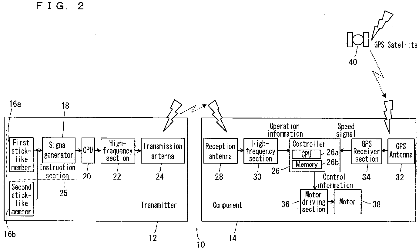
- the remote control device 10 includes a transmitter 12 which transmits signals toward the helicopter 1, and a component 14 which is installed in the helicopter 1.
- the transmitter 12 includes a first stick-like member 16a, a second stick-like member 16b, a signal generator 18, a CPU 20, a high-frequency section 22 and a transmission antenna 24.
- a motor 38 (which will be described later) is controlled to change an in-flight angle of a nose in an up-down direction, for acceleration or deceleration (forward or backward) of the helicopter 1.
- Moving the first stick-like member 16a in the direction a moves down the nose to cause the helicopter 1 to accelerate (flying forward), whereas moving the first stick-like member 16a in the direction b moves up the nose to cause the helicopter 1 to decelerate (flying backward).
- moving the first stick-like member 16a in directions cd causes the nose to turn in a left-right direction.
- Moving the second stick-like member 16b in directions ef (fore-aft direction) causes the helicopter body to ascend or descend.
- Moving the second stick-like member 16b in directions gh (left-right direction) causes the helicopter body to tilt leftward or rightward.
- the signal generator 18 generates analog operation information in accordance with an operation angle(s) of the first stick-like member 16a and/or the second stick-like member 16b from their baseline positions.
- the CPU 20 converts the given analog operation information into digital operation information, and sends it to the high-frequency section 22.
- the operation information includes a speed determination signal and a speed change signal.
- modulation with the digital operation information is performed, and an obtained radio signal is transmitted from the transmission antenna 24.
- speed of the helicopter 1 is instructed by an instruction section 25, which includes the first stick-like member 16a and the signal generator 18.
- the component 14 includes a controller 26, a reception antenna 28, a high-frequency section 30, a GPS antenna 32, a GPS receiver section 34, a motor driving section 36 and a motor 38.
- the radio signal which is sent from the transmission antenna 24 of the transmitter 12 is received by the reception antenna 28, and then demodulated by the high-frequency section 30 into digital operation information which represents the operation angles, and the information is supplied to the controller 26.
- GPS signals which are supplied from GPS satellites 40 and are relevant to the helicopter 1, are received by the GPS antenna 32 and supplied to the GPS receiver section 34.
- a speed signal which indicates a current speed of the helicopter 1 is extracted from the supplied GPS signals. The speed signal is supplied to the controller 26.
- the controller 26 includes a CPU 26a and a memory 26b.
- the CPU 26a (controller 26) executes programs stored in the memory 26b, and gives instructions to various constituent elements, thereby controlling the helicopter 1.
- the CPU 26a (controller 26) generates control information based on the supplied operation information and speed signal and controls the motor driving section 36.
- the motor driving section 36 drives the motor 38. By driving the motor 38, an angle of the main rotor 4 is changed to adjust an angle in an up-down direction of the nose of the in-flight helicopter 1.
- the instruction section 25 will be described here.
- the first stick-like member 16a is movable (tiltable) from a baseline position SP (neutral position) in a fore-aft direction (both positive and negative directions: directions ab).
- the first stick-like member 16a is movable in a range which includes a speed determination range D1 and a speed change range C1.
- a signal outputted from the signal generator 18 is a speed determination signal.
- a signal outputted from the signal generator 18 is a speed change signal.
- the instruction section 25 is capable of selectively outputting one of the speed change signal which is for changing the speed of the helicopter 1 and the speed determination signal which is for determining the speed of the helicopter 1.
- the speed change signal from the instruction section 25 (signal generator 18) is a signal which changes the speed of the helicopter 1 by changing the tilt angle of the nose in the up-down direction in accordance with an amount of operation made to the instruction section 25 (an operation angle X of the first stick-like member 16a).
- the baseline position SP is the speed determination range D1. Therefore, a slight tilting of the first stick-like member 16a from the baseline position SP in a fore-aft direction brings the first stick-like member 16a into the speed change range C1, causing the hovering helicopter 1 to start moving or causing the moving helicopter 1 which is flying at a constant speed, to change its flying speed (accelerate or decelerate). In other words, if the first stick-like member 16a is at the baseline position SP, the flying speed of the helicopter 1 does not change, and the state of hovering or flight at a constant speed is maintained. Fine tuning on the flying speed of the helicopter 1 is possible only when the first stick-like member 16a is moved into the speed change range C1.
- the speed change range C1 has a first change range C1a which is on the forward side (positive side) of the baseline position SP (speed determination range D1), and a second change range C1b which is on the rearward side (negative side) of the baseline position SP (speed determination range D1).
- the signal generator 18 When the first stick-like member 16a is in the first change range C1a, the signal generator 18 outputs a speed change signal for acceleration.
- the signal generator 18 When the first stick-like member 16a is in the second change range C1b, the signal generator 18 outputs a speed change signal for deceleration.
- the first stick-like member 16a is arranged to return to the baseline position SP when there is no force applied thereto.
- the operation angle X of the stick-like member 16a from the baseline position SP represents the amount of operation made to the instruction section 25.
- each of target tilt angle, operation angle X, target speed, current speed, basic attitude speed and limit value takes a positive (+) or a negative (-) value.
- target tilt angle refers to an angle of tilt in the up-down direction, of the nose of the helicopter 1 (helicopter body), as a target. The tilt angle is measured from a reference (zero) which is a value when the helicopter 1 is at a basic attitude (attitude of the helicopter 1 when the helicopter 1 is sitting on a horizontal plane).
- the target tilt angle takes a positive (+) value when the nose is tilting downward, and takes a negative (-) value when the nose is tilting upward.
- the operation angle X takes a positive (+) value when the first stick-like member 16a is located at a more forward position than the baseline position SP (neutral position), and takes a negative (-) value when located at a more rearward position.
- the helicopter body For unmanned helicopters to fly at a constant speed, the helicopter body must be maintained in the basic attitude. For this reason, there is a transition from a state where the helicopter body is at a tilt (current speed) to a state of the basic attitude, and during this transition, there is a slight acceleration or deceleration.
- the basic attitude speed refers to an estimated speed of the helicopter 1 at an expected time point when the helicopter body will attain the basic attitude from an attitude of the helicopter body at the time point of the speed estimation.
- the basic attitude speed is an estimated speed obtained by adding an acceleration or deceleration to be made until the time when the basic attitude is attained, to a speed signal (current speed) which is supplied from the GPS satellites 40 while the helicopter body is in a tilted state.
- the basic attitude speed is calculated by the CPU 26a (controller 26) from the current speed.
- the basic attitude speed represents the speed information. It should be noted here that if the helicopter body is already in the basic attitude when the basic attitude speed is calculated, then the basic attitude speed is equal to the current speed.
- Each of the target speed, the current speed, the basic attitude speed and the limit value takes a positive (+) value in a forward flight and a negative (-) value in a backward flight.
- Step S1 determines whether or not the first stick-like member 16a is located in the speed determination range D1. In other words, whether or not the first stick-like member 16a is at the baseline position SP is determined. The determination is made by the controller 26 in the component 14 based on operation information from the transmitter 12.
- Step S1 determines that the first stick-like member 16a is not in the speed determination range D1, but in the speed change range C1, then the process goes to Step S3.
- Step S3 means that the helicopter 1 is in an accelerating or decelerating state.
- the controller 26 sets the target tilt angle to a value in accordance with the operation angle X of the first stick-like member 16a, and then the process goes to Step S13.
- Step S13 determines whether or not an absolute value of the basic attitude speed of the helicopter 1 is not smaller than an absolute value of the limit value (20 km per hour, in the present embodiment).
- Step S15 the target speed of the helicopter 1 is set to the limit value (20 km per hour for forward flight and -20 km per hour for backward flight, in the present embodiment), and then the process goes to Step S11.
- Step S13 finds that the absolute value of the basic attitude speed of the helicopter 1 is smaller than the absolute value of the limit value, the process goes to Step S17, where the controller 26 calculates control information based on the target tilt angle of the helicopter 1, and then the process goes to Step S19.
- Step S1 finds that the first stick-like member 16a is in the speed determination range D1
- the process goes to Step S5.
- Step S5 means that the helicopter 1 is in a state of hovering or flight at a constant speed.
- Step S5 determines whether or not the absolute value of the basic attitude speed of the helicopter 1 is not smaller than a threshold value (10 km per hour, in the present embodiment). The determination is made based on the speed signal from the GPS satellites 40, by the controller 26 in the component 14. If the absolute value of the basic attitude speed of the helicopter 1 is smaller than the threshold value, the process goes to Step S7, where the target speed of the helicopter 1 is set to zero, and then the process goes to Step S11. On the other hand, if Step S5 finds that the absolute value of the basic attitude speed of the helicopter 1 is not smaller than the threshold value, the process goes to Step S9. In Step S9, the controller 26 sets the target speed of the helicopter 1 to the basic attitude speed of the helicopter 1. Then, the process goes to Step S11.
- Step S11 the controller 26 calculates control information based on the target speed of the helicopter 1, and then the process goes to Step S19.
- Step S19 the motor driving section 36 is controlled in accordance with the calculated control information, and the motor driving section 36 drives the motor 38 to change an angle of the main rotor 4, whereby the tilt angle of the nose of the in-flight helicopter 1 in the up-down direction is adjusted.
- Step S19 the process returns to Step S1.
- the control process shown in Fig. 4 is repeated at an interval of several milliseconds through several tens of milliseconds for example.
- the controller 26 controls the speed of the helicopter 1 based on instructions from the instruction section 25 (first stick-like member 16a).
- Step S17 In the control process shown in Fig. 4 , the process goes to Step S17 in a case where Steps S3 and S13 have been executed to lead to Step S17.
- the first stick-like member 16a is in the speed change range C1.
- a process through these Steps to lead to Step S17 represents the "attitude control".
- a case where the process moves through Steps S5 and S7 and then to Step S11 represents the case where the controller 26 sets the speed of the helicopter 1 to zero based on a comparison result between the basic attitude speed of the helicopter 1 and the threshold value when the position of the instruction section 25 (first stick-like member 16a) is changed from the speed change range C1 to the speed determination range D1, i.e., when the output from the instruction section 25 (signal generator 18) changes from the speed change signal to the speed determination signal.
- a case where the process moves through Steps S5 and S9 and then to Step S11 represents the case where the controller 26 maintains consistency of the speed of the helicopter 1 at the basic attitude speed based on a comparison result between the basic attitude speed of the helicopter 1 and the threshold value when the position of the instruction section 25 (first stick-like member 16a) is changed from the speed change range C1 to the speed determination range D1, i.e., when the output from the instruction section 25 (signal generator 18) changes from the speed change signal to the speed determination signal.
- the controller 26 in a state where the helicopter 1 is hovering and the first stick-like member 16a stays in the speed determination range D1, then the controller 26 maintains the helicopter 1 to hover.
- the controller 26 provides a control to bring a flying speed of the helicopter 1 to zero based on GPS signals from the GPS satellites 40 and therefore, reduces movement of the helicopter 1 even if there is an external factor such as wind.
- the controller 26 tilts the nose of the helicopter 1 downward thereby maintaining a forward tilting attitude of the helicopter body, so that the helicopter body keeps moving forward and keeps accelerating.
- the basic attitude speed is limited by the limit value ( ⁇ 20 km per hour, in the present embodiment). Therefore, when an absolute value of the basic attitude speed reaches the absolute value of the limit value, then the tilt angle of the nose of the helicopter 1 in the up-down direction is controlled to automatically bring the helicopter body into its horizontal attitude and to maintain the flying speed at the limit value.
- the controller 26 tilts the nose of the helicopter 1 upward to tilt the helicopter body rearward, so that the helicopter body decelerates. If the first stick-like member 16a stays in the second change range C1b of the speed change range C1, then the controller 26 keeps the helicopter body in a rearward tilting attitude, so the helicopter body keeps deceleration and eventually moves backward.
- the controller 26 compares the basic attitude speed of the helicopter 1 and the threshold value to each other. If an absolute value of the basic attitude speed of the helicopter 1 is not smaller than the threshold value, then the flying speed is brought to a constant level at the basic attitude speed. If the absolute value of the basic attitude speed is smaller than the threshold value, then the helicopter is brought into hovering.
- Line A shows a case where the speed of the helicopter 1 is controlled under a condition that the basic attitude speed of the helicopter 1 is greater than the threshold value.
- Line B shows a case where the speed of the helicopter 1 is controlled under a condition that the basic attitude speed of the helicopter 1 is smaller than the threshold value.
- Period (1) the first stick-like member 16a is in the second change range C1b, so the helicopter 1 decelerates.
- Period (2) starts with a basic attitude speed being greater than the threshold value.
- the helicopter 1 keeps the basic attitude speed of the time point when it entered Period (2).
- Period (3) the first stick-like member 16a is moved "from the first change range C1a ⁇ the speed determination range D1 ⁇ the first change range C1a ⁇ the speed determination range D1 ⁇ the second change range C1b ⁇ the speed determination range D1".
- the speed of the helicopter 1 is increased/decreased, to make fine adjustments on a constant speed.
- Period (4) As the first stick-like member 16a stays in the speed determination range D1, the helicopter 1 keeps a basic attitude speed of the time when it entered Period (4). Thereafter, as Period (5) starts, the first stick-like member 16a is moved to and kept in the first change range C1a, then the speed of the helicopter 1 increases until the limit value is reached. If the first stick-like member 16a continues to stay in the first change range C1a thereafter, then the speed of the helicopter 1 is maintained at the limit value.
- Period (1) the helicopter 1 is at a speed of zero (hovering), upon which the first stick-like member 16a is moved to and kept in the first change range C1a. Then, the speed of the helicopter 1 keeps increasing. However, the helicopter 1 enters Period (2) before its basic attitude speed reaches the threshold value. As the first stick-like member 16a is returned to the speed determination range D1, the helicopter 1 decelerates and the speed is eventually returned to zero to come into the state of hovering. In Period (3) thereafter, the first stick-like member 16a is moved to and kept in the first change range C1a. Then, the speed of the helicopter 1 keeps increasing. However, the helicopter 1 enters Period (4) before its basic attitude speed reaches the threshold value.
- the helicopter 1 decelerates and the speed is eventually returned to zero to come into the state of hovering. Thereafter, as Period (5) starts, the first stick-like member 16a is moved to and kept in the first change range C1a, then the speed of the helicopter 1 increases until the limit value is reached. If the first stick-like member 16a continues to stay in the first change range C1a thereafter, then the speed of the helicopter 1 is maintained at the limit value.
- the helicopter 1 accelerates or decelerates as the operator outputs a speed change signal from the instruction section 25. Then, as the operator changes the output from the instruction section 25, from the speed change signal to a speed determination signal, a comparison is made between a basic attitude speed of the helicopter 1 at this specific time point and the threshold value. If the absolute value of the basic attitude speed of the helicopter 1 is not smaller than the threshold value, the tilt angle of the nose of the helicopter 1 in the up-down direction is controlled to keep the speed of the helicopter 1.
- the tilt angle of the nose of the helicopter 1 in the up-down direction is controlled to bring the speed of the helicopter 1 to zero, so that the helicopter 1 is brought into a state of hovering (or is maintained in the state of hovering).
- the absolute value of the basic attitude speed of the helicopter 1 is not smaller than the threshold value, it is possible to fine-tune the speed of the helicopter 1 by quickly alternating the output from the instruction section 25 between the speed change signal and the speed determination signal, and then keep a desired speed. As understood, it is possible to keep the helicopter 1 at a desired speed easily by simply changing the output from the instruction section 25, from the speed change signal to the speed determination signal.
- the helicopter 1 is in the "attitude control" state when the speed change signal is outputted from the instruction section 25, except for the case where the absolute value of the basic attitude speed of the helicopter 1 is not smaller than the absolute value of the limit value.
- the state in which the speed determination signal is outputted is a state where the speed of the helicopter 1 is maintained at a constant speed.
- the first change range C1a and the second change range C1b are arranged in directions away from each other as viewed from the baseline position SP. This simplifies and clarifies operations which must be performed to the instruction section 25 by the operator when accelerating or decelerating the helicopter 1. It is possible to control easily forward moving speed and backward moving speed of the helicopter 1, and to decrease misoperations.
- the speed of the helicopter 1 is changed in accordance with the operation angle X of the first stick-like member 16a. Then, as the operator returns the first stick-like member 16a from the speed change range C1 into the speed determination range D1, a basic attitude speed of the helicopter 1 at this time point is compared to a threshold value, and based on a comparison result, the speed of the helicopter 1 is maintained or the helicopter 1 is brought into a hovering state. In other words, if the absolute value of the basic attitude speed of the helicopter 1 is not smaller than the threshold value, a control is performed to keep the speed of the helicopter 1 at the basic attitude speed.
- the first stick-like member 16a of changing the output from the instruction section 25, from the speed change signal to the speed determination signal makes it possible to easily keep the helicopter 1 at a desired speed. Also, the first stick-like member 16a returns to the baseline position SP if it receives no force.
- the operator needs to apply his/her force in order to tilt the first stick-like member 16a only when he/she wants to accelerate or decelerate the helicopter 1, i.e., he/she does not have to manipulate the first stick-like member 16a for maintaining the speed of the helicopter 1.
- the first stick-like member 16a returns to the baseline position SP if there is no operation being made to the first stick-like member 16a, it is possible to prevent undesired acceleration and deceleration of the helicopter 1.
- the helicopter 1 makes a flight at a constant speed over the target area of application. Since the helicopter 1 can fly at a desired speed easily and at a constant speed as well, it is applicable suitably to application of agricultural chemicals.
- the baseline position SP represents the speed determination range D1.
- the speed determination range D2 may be a predetermined range provided in a fore-aft direction to sandwich the baseline position SP.
- the speed determination range D2 may be on both positive and negative sides of the baseline position SP, and include the baseline position SP.
- a speed change range C2 is provided in front of and behind the speed determination range D2.
- the speed change range C2 has a first change range C2a which is on an outer side of the speed determination range D2 and in front (on the positive side) of the baseline position SP, and a second change range C2b which is on an outer side of the speed determination range D2 and behind (on the negative side of) the baseline position SP.
- Such an arrangement i.e., that the speed determination range D2 is between the baseline position SP and the speed change range C2, so that the instruction section 25 (first stick-like member 16a) cannot reach the speed change range C2 unless it is moved from the baseline position SP and through the speed determination range D2, makes the speed determination range D2 function as so-called "play" zone in relation to speed change operation of the helicopter 1. Therefore, it becomes possible to prevent speed changes of the helicopter 1 which are not intended by the operator.
- the arrangement makes it possible to change the speed of the helicopter 1 easily, only when the operator wants to do so.
- the operator can keep the helicopter 1 at a desired speed easily by outputting a speed determination signal from the instruction section 25 in whichever control of the "attitude control” and the "speed control" he/she selects when outputting the speed change signal from the instruction section 25.
- the remote control device 10 is suitable for whichever type of operators, i.e., those who prefer “attitude control” and those who prefer “speed control”.
- the present invention is not limited to this.
- the speed of the helicopter 1 is maintained if the absolute value of the basic attitude speed of the helicopter 1 is greater than a threshold value, whereas the speed of the helicopter 1 is brought to zero if the absolute value of the basic attitude speed of the helicopter 1 is not greater than the threshold value.
- the absolute value of the basic attitude speed of the helicopter 1 is greater than the threshold value, it is possible to fine-tune the speed of the helicopter 1 by quickly alternating the output from the instruction section 25 between the speed change signal and the speed determination signal.
- speed information is provided by the basic attitude speed.
- the speed information may be provided by the current speed instead of the basic attitude speed.
- determination on whether the speed of the helicopter 1 is maintained or brought to zero is based on a result of comparison between the current speed and a threshold value.
- the instruction section is not limited to a stick-like member.
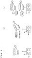
- the instruction section may be provided by a lever movable in a fore-aft direction as shown in Fig. 7(a) , a pivotable steering wheel as shown in Fig. 7(b) , a stool or a table tiltable in a fore-aft direction (weight-shiftable forward/rearward) as shown in Fig. 7(c) , a rotatable ball as shown in Fig. 7(d) , etc., for example.
- the instruction section may include a plurality of button-like members, such as a button-like member capable of outputting a speed change signal and a button-like member capable of outputting a speed determination signal.
- Transportation equipment to which the present invention is applied preferably is a piece of equipment which requires control for "moving at a constant speed" or “staying still at a position", e.g. those being unstable in a still state and moving by inertia on the ground, in the air, under or in the water, or on the ice or snow.
- spherical bodies which move on the ground, monocycles or bicycles (electric two-wheel stand-ride scooters etc.), boats which move in the water, hovercrafts which move on ice and snow, submarines which move under the water, etc. are usable. It should be noted here that for submarines, speed detection will be possible by arranging the GPS antenna to stay above the water, or by employing an inertia navigation method by way of acceleration sensors.
Landscapes
- Engineering & Computer Science (AREA)
- Physics & Mathematics (AREA)
- Aviation & Aerospace Engineering (AREA)
- Remote Sensing (AREA)
- General Physics & Mathematics (AREA)
- Automation & Control Theory (AREA)
- Radar, Positioning & Navigation (AREA)
- Computer Networks & Wireless Communication (AREA)
- Mechanical Engineering (AREA)
- Theoretical Computer Science (AREA)
- Mathematical Physics (AREA)
- Computing Systems (AREA)
- Toys (AREA)
- Control Of Position, Course, Altitude, Or Attitude Of Moving Bodies (AREA)
Abstract
Description
- The present invention relates to remote control devices, and more specifically to a remote control device which is used to control transportation equipment such as an unmanned helicopter.
- An example of conventional techniques in this kind is disclosed in
Patent Literature 1. -
Patent Literature 1 discloses an operation assisting device for an unmanned radio-controlled helicopter. The operation assisting device is interposed between a receiver and servo motors in a conventional unmanned radio-controlled helicopter, and is composed of a microcomputer, a PWM signal reading circuit, a PWM signal generation circuit, a PWM signal switching circuit, and various sensors. With the arrangement described above, hovering is performed when the operator's operation is in neutral, and when there is an operation by the operator, the servo motors are controlled accordingly or an amount of the operation is interpreted as a target value and the control is performed to follow the value. - Patent Literature 1:
JP-A 2009-96369 - However, if a desired flying speed is to be maintained at a constant level, the above-described operation assisting device is difficult for an operator to operate and requires a high level of skills. In particular, under external conditions such as strong winds, it becomes even more difficult to maintain a constant flying speed of the helicopter stably.
- Therefore, a primary object of the present invention is to provide a remote control device capable of easily maintaining transportation equipment at a desired speed.
- According to an aspect of the present invention, there is provided a remote control device of transportation equipment, which includes an instruction section which instructs a speed of the transportation equipment; and a controller which controls the speed of the transportation equipment based on the instruction from the instruction section. In this device, the instruction section is capable of selectively outputting one of a speed change signal for changing the speed of the transportation equipment and a speed determination signal for determining the speed of the transportation equipment; and the controller determines whether the speed of the transportation equipment should be maintained or brought to zero based on a result of comparison between speed information of the transportation equipment and a threshold value, when the output from the instruction section is changed from the speed change signal to the speed determination signal.
- According to the present invention, the operator outputs a speed change signal from the instruction section, whereupon the transportation equipment accelerates or decelerates. Then, as the operator changes the output from the instruction section, from the speed change signal to a speed determination signal, a comparison is made between speed information of the transportation equipment at this specific time point and the threshold value. If an absolute value of the speed information of the transportation equipment is not smaller than the threshold value (or greater than the threshold value), the speed of the transportation equipment is maintained. On the other hand, if the absolute value of the speed information of the transportation equipment is smaller than the threshold value (or not greater than the threshold value), the speed of the transportation equipment is brought to zero, and the transportation equipment is stopped. Also, if the absolute value of the speed information of the transportation equipment is not smaller than the threshold value (or greater than the threshold value), it is possible to fine-tune the speed of the transportation equipment by quickly alternating the output from the instruction section between the speed change signal and the speed determination signal, and then keep a desired speed. As understood, it is possible to keep the transportation equipment at a desired speed easily by simply changing the output from the instruction section, from the speed change signal to the speed determination signal.
- Generally, when remotely controlling an unmanned helicopter, an instruction section in a remote control device is operated to change a tilt angle of a nose of the unmanned helicopter in an up-down direction for varying the speed of the unmanned helicopter. The speed of the unmanned helicopter can be controlled in two methods, i.e., so-called "attitude control" and so-called "speed control". In the "attitude control", a tilt angle of the nose in an up-down direction is changed in accordance with an amount of operation made to the instruction section, whereby the speed of the unmanned helicopter is varied. In the "speed control", a tilt angle of the nose in an up-down direction is varied so as to attain a target speed corresponding to an amount of operation made to the instruction section, and once the target speed is attained, this speed becomes a target speed to maintain. Each operator uses one of the "attitude control" and the "speed control" as his/her main method to remotely control an unmanned helicopter depending on his/her preference, an amount of experience, etc. In the present invention, preferably, the transportation equipment is provided by an unmanned helicopter. In this case, when outputting the speed change signal from the instruction section, the operator can easily keep the unmanned helicopter at a desired speed by simply outputting the speed determination signal from the instruction section in whichever control of the "attitude control" and the "speed control" he/she selects. Therefore, the present invention is suitable for whichever type of operators, i.e., those who prefer the "attitude control" and those who prefer the "speed control".
- Generally, the remote control device includes a switch or the like for switching between the "attitude control" and the "speed control" aside from the instruction section for instruction on the speed. In the "attitude control" where the tilt angle of the nose in the up-down direction is changed in accordance with the amount of operation made to the instruction section, it is difficult to control the helicopter to fly at a constant speed or hover continuously because if the amount of operation made to the instruction section is maintained at a constant level in order to tilt the nose obliquely downward, then a helicopter body moves forward at an accelerating speed. In such a case, the switch or the like is used to change from the "attitude control" to the "speed control". In the "speed control", a process to attain the target speed is based on speed signals obtained from GPS satellites. If signals from the GPS satellites are unavailable, it becomes impossible to control the speed. In such a case, the switch or the like must be used to change from the "speed control" to the "attitude control". In addition to these, the helicopter body moves differently when it is in the "attitude control" and when it is in the "speed control" even if the amount of operation made to the instruction section is the same, and therefore operational feeling of the instruction section is different. Consequently, the operator must have a high level of operation skills in order to control the helicopter as desired even right after a change-over between the "attitude control" and the "speed control". In the present invention, preferably, the speed change signal is a signal which changes the speed of the unmanned helicopter by changing a tilt angle of a nose of the unmanned helicopter in an up-down direction in accordance with an amount of operation made to the instruction section. In this case, the helicopter is in the "attitude control" when the speed change signal is outputted from the instruction section. When the speed determination signal is outputted, the unmanned helicopter is in a state of being maintained at a constant speed. Hence, with a simple change from the "attitude control" where the speed change signal is outputted from the instruction section to a state where the speed determination signal is outputted, it becomes easy to fly the unmanned helicopter at a constant speed, or to change from flying in a low speed range to hovering. There is no need for the operator to operate a switch or the like for making a change between the "attitude control" and the "speed control" other than the instruction section. Further, the operator is not required to have a high level of operation skills because as far as the instruction section is outputting the speed change signal (in other words, when changing the speed), the helicopter is in the "attitude control" so he/she can make operation without any difference from a case where the "attitude control" has been selected specifically by using a specific switch or the like.
- Preferably, the instruction section is movable from a baseline position. In this arrangement, the instruction section is movable in a range which includes a speed determination range for outputting the speed determination signal from the instruction section and a speed change range for outputting the speed change signal from the instruction section. The speed determination range includes the baseline position, whereas the speed change range is on an outer side of the speed determination range as viewed from the baseline position. With the above arrangement, the controller determines whether the speed of the transportation equipment should be maintained or brought to zero based on a result of comparison between speed information of the transportation equipment and the threshold value, when the instruction section is moved from the speed change range into the speed determination range. In this case, when the operator moves the instruction section from the baseline position, passing through the speed determination range, into the speed change range, then the speed of the transportation equipment is changed in accordance with the amount of operation made to the instruction section. Then, as the operator returns the instruction section from the speed change range to the speed determination range (typically to the baseline position), the speed information of the transportation equipment at this time point is compared to the threshold value, and based on a comparison result, the speed of the transportation equipment is maintained or brought to zero. Such an arrangement, i.e., that the speed determination range is between the baseline position and the speed change range, so that the instruction section cannot reach the speed change range unless it is moved from the baseline position and through the speed determination range, makes the speed determination range function as so-called "play" zone in relation to speed change operation of the transportation equipment. Therefore, it becomes possible to prevent unintentional speed changes of the transportation equipment which are not intended by the operator. The arrangement makes it possible to change the speed of the transportation equipment easily and only when the operator wants to do so.
- Further preferably, the instruction section is movable in both of a positive and a negative directions from the baseline position. In this arrangement, the speed determination range includes the baseline position, and is on both positive and negative sides of the baseline position; the speed change range includes a first change range on the positive side of the baseline position and a second change range on the negative side of the baseline position, on the outer side of the speed determination range as viewed from the baseline position. With the above arrangement, the instruction section outputs a speed change signal for acceleration when the instruction section is in the first change range, whereas the instruction section outputs a speed change signal for deceleration when the instruction section is in the second change range. In this case, the first change range and the second change range are arranged in directions away from each other as viewed from the baseline position. This makes operations easy and clear when the operator accelerates or decelerates the transportation equipment using the instruction section. It is possible to control easily forward moving speed and backward moving speed of the transportation equipment, and to decrease misoperations.
- Further, preferably, the instruction section includes a stick-like member which returns to the baseline position unless a force is applied, and an operation angle of the stick-like member represents an amount of operation made to the instruction section. In this case, when the operator tilts the stick-like member from the baseline position, passing through the speed determination range, into the speed change range, then the speed of the transportation equipment is changed in accordance with the operation angle of the stick-like member. Then, as the operator returns the stick-like member from the speed change range to the speed determination range, the speed information of the transportation equipment at this time point is compared to the threshold value, and based on a comparison result, the speed of the transportation equipment is maintained or brought to zero. In other words, if an absolute value of the speed information of the transportation equipment is not smaller than the threshold value (greater than the threshold value), a control is provided to maintain the speed of the transportation equipment. On the other hand, if the absolute value of the speed information of the transportation equipment is smaller than the threshold value (not greater than the threshold value), a control is provided to bring the speed of the transportation equipment to zero (and then maintain thereafter). As understood, it is possible to keep the transportation equipment at a desired speed easily by simply operating the stick-like member thereby changing the output from the instruction section, from the speed change signal to the speed determination signal. Also, the stick-like member returns to the baseline position if no force is applied. Therefore, the operator should apply a force to tilt the stick-like member only when accelerating or decelerating the transportation equipment, and there is no need to make any operation on the stick-like member to maintain the speed of the transportation equipment. This makes operation of the instruction section easy. Further, since the stick-like member returns to the baseline position if there is no operation being made to the stick-like member, it is possible to prevent undesired acceleration and deceleration of the transportation equipment.
- The above-described object and other objects, characteristics, aspects and advantages of the present invention will become clearer from the following detailed description of embodiments of the present invention to be made with reference to the attached drawings.
-
-
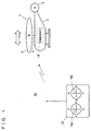
Fig. 1 is an illustrative drawing which shows an embodiment of the present invention, where transportation equipment is provided by an unmanned helicopter. -
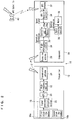
Fig. 2 is an electrical block diagram which shows a configuration example of a remote control device. -
Fig. 3 is an illustrative drawing which shows ranges of movement of a first stick-like member. -
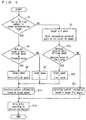
Fig. 4 is a flowchart which shows an example of control process by the remote control device. -
Fig. 5 is an illustrative drawing for describing behavior of the unmanned helicopter. -
Fig. 6 is a graph which shows examples of time-course speed changes in the unmanned helicopter. -
Fig. 7 is an illustrative drawing which shows variations of an instruction section. - Hereinafter, embodiments of the present invention will be described with reference to the drawings.
- In an embodiment shown in
Fig. 1 , transportation equipment is provided by an unmanned helicopter 1 (hereinafter, simplified as helicopter 1). Therefore, aremote control device 10 according to the embodiment shown inFig. 1 is a remote control device for thehelicopter 1. - The
helicopter 1 includes abody 2, amast 3, amain rotor 4 and atail rotor 5. Themast 3 protrudes upward from thebody 2, and is rotatable. Themast 3 has an upper end portion, where themain rotor 4 is fixed. Thetail rotor 5 is rotatable, and is at a rear end portion of thebody 2. Themain rotor 4 and thetail rotor 5 are rotated based on a driving force from an unillustrated drive source. - The
remote control device 10 includes atransmitter 12 which transmits signals toward thehelicopter 1, and acomponent 14 which is installed in thehelicopter 1. - Referring to
Fig. 2 , thetransmitter 12 includes a first stick-like member 16a, a second stick-like member 16b, asignal generator 18, aCPU 20, a high-frequency section 22 and atransmission antenna 24. - Referring to
Fig. 1 , when the first stick-like member 16a is moved in directions ab (fore-aft direction), a motor 38 (which will be described later) is controlled to change an in-flight angle of a nose in an up-down direction, for acceleration or deceleration (forward or backward) of thehelicopter 1. Moving the first stick-like member 16a in the direction a moves down the nose to cause thehelicopter 1 to accelerate (flying forward), whereas moving the first stick-like member 16a in the direction b moves up the nose to cause thehelicopter 1 to decelerate (flying backward). - Also, moving the first stick-
like member 16a in directions cd (left-right direction) causes the nose to turn in a left-right direction. Moving the second stick-like member 16b in directions ef (fore-aft direction) causes the helicopter body to ascend or descend. Moving the second stick-like member 16b in directions gh (left-right direction) causes the helicopter body to tilt leftward or rightward. - The
signal generator 18 generates analog operation information in accordance with an operation angle(s) of the first stick-like member 16a and/or the second stick-like member 16b from their baseline positions. TheCPU 20 converts the given analog operation information into digital operation information, and sends it to the high-frequency section 22. The operation information includes a speed determination signal and a speed change signal. In the high-frequency section 22, modulation with the digital operation information is performed, and an obtained radio signal is transmitted from thetransmission antenna 24. - In the present embodiment, speed of the
helicopter 1 is instructed by aninstruction section 25, which includes the first stick-like member 16a and thesignal generator 18. - The
component 14 includes acontroller 26, areception antenna 28, a high-frequency section 30, aGPS antenna 32, aGPS receiver section 34, a motor driving section 36 and amotor 38. - The radio signal which is sent from the
transmission antenna 24 of thetransmitter 12 is received by thereception antenna 28, and then demodulated by the high-frequency section 30 into digital operation information which represents the operation angles, and the information is supplied to thecontroller 26. Also, GPS signals, which are supplied fromGPS satellites 40 and are relevant to thehelicopter 1, are received by theGPS antenna 32 and supplied to theGPS receiver section 34. In theGPS receiver section 34, a speed signal which indicates a current speed of thehelicopter 1 is extracted from the supplied GPS signals. The speed signal is supplied to thecontroller 26. - The
controller 26 includes a CPU 26a and amemory 26b. The CPU 26a (controller 26) executes programs stored in thememory 26b, and gives instructions to various constituent elements, thereby controlling thehelicopter 1. For example, the CPU 26a (controller 26) generates control information based on the supplied operation information and speed signal and controls the motor driving section 36. The motor driving section 36 drives themotor 38. By driving themotor 38, an angle of themain rotor 4 is changed to adjust an angle in an up-down direction of the nose of the in-flight helicopter 1. - The
instruction section 25 will be described here. - Referring also to
Fig. 3(a) , the first stick-like member 16a is movable (tiltable) from a baseline position SP (neutral position) in a fore-aft direction (both positive and negative directions: directions ab). The first stick-like member 16a is movable in a range which includes a speed determination range D1 and a speed change range C1. When the first stick-like member 16a is in the speed determination range D1, a signal outputted from thesignal generator 18 is a speed determination signal. When the first stick-like member 16a is in the speed change range C1, a signal outputted from thesignal generator 18 is a speed change signal. In other words, theinstruction section 25 is capable of selectively outputting one of the speed change signal which is for changing the speed of thehelicopter 1 and the speed determination signal which is for determining the speed of thehelicopter 1. The speed change signal from the instruction section 25 (signal generator 18) is a signal which changes the speed of thehelicopter 1 by changing the tilt angle of the nose in the up-down direction in accordance with an amount of operation made to the instruction section 25 (an operation angle X of the first stick-like member 16a). - In the present embodiment, the baseline position SP is the speed determination range D1. Therefore, a slight tilting of the first stick-
like member 16a from the baseline position SP in a fore-aft direction brings the first stick-like member 16a into the speed change range C1, causing the hoveringhelicopter 1 to start moving or causing the movinghelicopter 1 which is flying at a constant speed, to change its flying speed (accelerate or decelerate). In other words, if the first stick-like member 16a is at the baseline position SP, the flying speed of thehelicopter 1 does not change, and the state of hovering or flight at a constant speed is maintained. Fine tuning on the flying speed of thehelicopter 1 is possible only when the first stick-like member 16a is moved into the speed change range C1. - The speed change range C1 has a first change range C1a which is on the forward side (positive side) of the baseline position SP (speed determination range D1), and a second change range C1b which is on the rearward side (negative side) of the baseline position SP (speed determination range D1). When the first stick-
like member 16a is in the first change range C1a, thesignal generator 18 outputs a speed change signal for acceleration. When the first stick-like member 16a is in the second change range C1b, thesignal generator 18 outputs a speed change signal for deceleration. The first stick-like member 16a is arranged to return to the baseline position SP when there is no force applied thereto. The operation angle X of the stick-like member 16a from the baseline position SP represents the amount of operation made to theinstruction section 25. - Referring to
Fig. 4 , description will cover an example of control process by theremote control device 10 while thehelicopter 1 is in flight. It should be noted here that each of target tilt angle, operation angle X, target speed, current speed, basic attitude speed and limit value takes a positive (+) or a negative (-) value. The term target tilt angle refers to an angle of tilt in the up-down direction, of the nose of the helicopter 1 (helicopter body), as a target. The tilt angle is measured from a reference (zero) which is a value when thehelicopter 1 is at a basic attitude (attitude of thehelicopter 1 when thehelicopter 1 is sitting on a horizontal plane). The target tilt angle takes a positive (+) value when the nose is tilting downward, and takes a negative (-) value when the nose is tilting upward. The operation angle X takes a positive (+) value when the first stick-like member 16a is located at a more forward position than the baseline position SP (neutral position), and takes a negative (-) value when located at a more rearward position. For unmanned helicopters to fly at a constant speed, the helicopter body must be maintained in the basic attitude. For this reason, there is a transition from a state where the helicopter body is at a tilt (current speed) to a state of the basic attitude, and during this transition, there is a slight acceleration or deceleration. From these, the basic attitude speed refers to an estimated speed of thehelicopter 1 at an expected time point when the helicopter body will attain the basic attitude from an attitude of the helicopter body at the time point of the speed estimation. Typically, the basic attitude speed is an estimated speed obtained by adding an acceleration or deceleration to be made until the time when the basic attitude is attained, to a speed signal (current speed) which is supplied from theGPS satellites 40 while the helicopter body is in a tilted state. Thus, the basic attitude speed is calculated by the CPU 26a (controller 26) from the current speed. In the present embodiment, the basic attitude speed represents the speed information. It should be noted here that if the helicopter body is already in the basic attitude when the basic attitude speed is calculated, then the basic attitude speed is equal to the current speed. Each of the target speed, the current speed, the basic attitude speed and the limit value takes a positive (+) value in a forward flight and a negative (-) value in a backward flight. - First, Step S1 determines whether or not the first stick-
like member 16a is located in the speed determination range D1. In other words, whether or not the first stick-like member 16a is at the baseline position SP is determined. The determination is made by thecontroller 26 in thecomponent 14 based on operation information from thetransmitter 12. - If Step S1 determines that the first stick-
like member 16a is not in the speed determination range D1, but in the speed change range C1, then the process goes to Step S3. Moving to Step S3 means that thehelicopter 1 is in an accelerating or decelerating state. In Step S3, thecontroller 26 sets the target tilt angle to a value in accordance with the operation angle X of the first stick-like member 16a, and then the process goes to Step S13. Step S13 determines whether or not an absolute value of the basic attitude speed of thehelicopter 1 is not smaller than an absolute value of the limit value (20 km per hour, in the present embodiment). If the absolute value of the basic attitude speed of thehelicopter 1 is not smaller than the absolute value of the limit value, the process goes to Step S15, where the target speed of thehelicopter 1 is set to the limit value (20 km per hour for forward flight and -20 km per hour for backward flight, in the present embodiment), and then the process goes to Step S11. On the other hand, if Step S13 finds that the absolute value of the basic attitude speed of thehelicopter 1 is smaller than the absolute value of the limit value, the process goes to Step S17, where thecontroller 26 calculates control information based on the target tilt angle of thehelicopter 1, and then the process goes to Step S19. - On the other hand, if Step S1 finds that the first stick-
like member 16a is in the speed determination range D1, the process goes to Step S5. Moving to Step S5 means that thehelicopter 1 is in a state of hovering or flight at a constant speed. - Step S5 determines whether or not the absolute value of the basic attitude speed of the
helicopter 1 is not smaller than a threshold value (10 km per hour, in the present embodiment). The determination is made based on the speed signal from theGPS satellites 40, by thecontroller 26 in thecomponent 14. If the absolute value of the basic attitude speed of thehelicopter 1 is smaller than the threshold value, the process goes to Step S7, where the target speed of thehelicopter 1 is set to zero, and then the process goes to Step S11. On the other hand, if Step S5 finds that the absolute value of the basic attitude speed of thehelicopter 1 is not smaller than the threshold value, the process goes to Step S9. In Step S9, thecontroller 26 sets the target speed of thehelicopter 1 to the basic attitude speed of thehelicopter 1. Then, the process goes to Step S11. - In Step S11, the
controller 26 calculates control information based on the target speed of thehelicopter 1, and then the process goes to Step S19. - In Step S19, the motor driving section 36 is controlled in accordance with the calculated control information, and the motor driving section 36 drives the
motor 38 to change an angle of themain rotor 4, whereby the tilt angle of the nose of the in-flight helicopter 1 in the up-down direction is adjusted. After Step S19, the process returns to Step S1. In the present embodiment, the control process shown inFig. 4 is repeated at an interval of several milliseconds through several tens of milliseconds for example. - In accordance with the above-described control process by the
remote control device 10, thecontroller 26 controls the speed of thehelicopter 1 based on instructions from the instruction section 25 (first stick-like member 16a). - In the control process shown in
Fig. 4 , the process goes to Step S17 in a case where Steps S3 and S13 have been executed to lead to Step S17. In this case the first stick-like member 16a is in the speed change range C1. A process through these Steps to lead to Step S17 represents the "attitude control". - Also, in the control process shown in
Fig. 4 , a case where the process moves through Steps S5 and S7 and then to Step S11 represents the case where thecontroller 26 sets the speed of thehelicopter 1 to zero based on a comparison result between the basic attitude speed of thehelicopter 1 and the threshold value when the position of the instruction section 25 (first stick-like member 16a) is changed from the speed change range C1 to the speed determination range D1, i.e., when the output from the instruction section 25 (signal generator 18) changes from the speed change signal to the speed determination signal. - A case where the process moves through Steps S5 and S9 and then to Step S11 represents the case where the
controller 26 maintains consistency of the speed of thehelicopter 1 at the basic attitude speed based on a comparison result between the basic attitude speed of thehelicopter 1 and the threshold value when the position of the instruction section 25 (first stick-like member 16a) is changed from the speed change range C1 to the speed determination range D1, i.e., when the output from the instruction section 25 (signal generator 18) changes from the speed change signal to the speed determination signal. - Referring to
Fig. 5(a) , in a state where thehelicopter 1 is hovering and the first stick-like member 16a stays in the speed determination range D1, then thecontroller 26 maintains thehelicopter 1 to hover. In this case, thecontroller 26 provides a control to bring a flying speed of thehelicopter 1 to zero based on GPS signals from theGPS satellites 40 and therefore, reduces movement of thehelicopter 1 even if there is an external factor such as wind. - Referring to
Fig. 5 (b) , if the first stick-like member 16a stays in the first change range C1a of the speed change range C1, then thecontroller 26 tilts the nose of thehelicopter 1 downward thereby maintaining a forward tilting attitude of the helicopter body, so that the helicopter body keeps moving forward and keeps accelerating. However, the basic attitude speed is limited by the limit value (±20 km per hour, in the present embodiment). Therefore, when an absolute value of the basic attitude speed reaches the absolute value of the limit value, then the tilt angle of the nose of thehelicopter 1 in the up-down direction is controlled to automatically bring the helicopter body into its horizontal attitude and to maintain the flying speed at the limit value. - Thereafter, if the first stick-
like member 16a is moved from the first change range C1a to the second change range C1b of the speed change range C1, then thecontroller 26 tilts the nose of thehelicopter 1 upward to tilt the helicopter body rearward, so that the helicopter body decelerates. If the first stick-like member 16a stays in the second change range C1b of the speed change range C1, then thecontroller 26 keeps the helicopter body in a rearward tilting attitude, so the helicopter body keeps deceleration and eventually moves backward. - Referring to
Fig. 5 (c) , if the first stick-like member 16a is moved from the first change range C1a of the speed change range C1 to the speed determination range D1, then thecontroller 26 compares the basic attitude speed of thehelicopter 1 and the threshold value to each other. If an absolute value of the basic attitude speed of thehelicopter 1 is not smaller than the threshold value, then the flying speed is brought to a constant level at the basic attitude speed. If the absolute value of the basic attitude speed is smaller than the threshold value, then the helicopter is brought into hovering. - Referring to
Fig. 6 , description will cover examples of time-course speed changes of thehelicopter 1. - In
Fig. 6 , Line A shows a case where the speed of thehelicopter 1 is controlled under a condition that the basic attitude speed of thehelicopter 1 is greater than the threshold value. Line B shows a case where the speed of thehelicopter 1 is controlled under a condition that the basic attitude speed of thehelicopter 1 is smaller than the threshold value. - First, description will be made for Line A.
- In Period (1), the first stick-
like member 16a is in the second change range C1b, so thehelicopter 1 decelerates. Period (2) starts with a basic attitude speed being greater than the threshold value. As the first stick-like member 16a stays in the speed determination range D1, thehelicopter 1 keeps the basic attitude speed of the time point when it entered Period (2). In Period (3), the first stick-like member 16a is moved "from the first change range C1a → the speed determination range D1 → the first change range C1a → the speed determination range D1 → the second change range C1b → the speed determination range D1". In accordance with the operation made to the first stick-like member 16a, the speed of thehelicopter 1 is increased/decreased, to make fine adjustments on a constant speed. In Period (4), as the first stick-like member 16a stays in the speed determination range D1, thehelicopter 1 keeps a basic attitude speed of the time when it entered Period (4). Thereafter, as Period (5) starts, the first stick-like member 16a is moved to and kept in the first change range C1a, then the speed of thehelicopter 1 increases until the limit value is reached. If the first stick-like member 16a continues to stay in the first change range C1a thereafter, then the speed of thehelicopter 1 is maintained at the limit value. - Next, Line B will be described.
- In Period (1), the
helicopter 1 is at a speed of zero (hovering), upon which the first stick-like member 16a is moved to and kept in the first change range C1a. Then, the speed of thehelicopter 1 keeps increasing. However, thehelicopter 1 enters Period (2) before its basic attitude speed reaches the threshold value. As the first stick-like member 16a is returned to the speed determination range D1, thehelicopter 1 decelerates and the speed is eventually returned to zero to come into the state of hovering. In Period (3) thereafter, the first stick-like member 16a is moved to and kept in the first change range C1a. Then, the speed of thehelicopter 1 keeps increasing. However, thehelicopter 1 enters Period (4) before its basic attitude speed reaches the threshold value. As the first stick-like member 16a is returned to the speed determination range D1, thehelicopter 1 decelerates and the speed is eventually returned to zero to come into the state of hovering. Thereafter, as Period (5) starts, the first stick-like member 16a is moved to and kept in the first change range C1a, then the speed of thehelicopter 1 increases until the limit value is reached. If the first stick-like member 16a continues to stay in the first change range C1a thereafter, then the speed of thehelicopter 1 is maintained at the limit value. - According to the
remote control device 10 as described above, thehelicopter 1 accelerates or decelerates as the operator outputs a speed change signal from theinstruction section 25. Then, as the operator changes the output from theinstruction section 25, from the speed change signal to a speed determination signal, a comparison is made between a basic attitude speed of thehelicopter 1 at this specific time point and the threshold value. If the absolute value of the basic attitude speed of thehelicopter 1 is not smaller than the threshold value, the tilt angle of the nose of thehelicopter 1 in the up-down direction is controlled to keep the speed of thehelicopter 1. On the other hand, if the absolute value of the basic attitude speed of thehelicopter 1 is smaller than the threshold value, the tilt angle of the nose of thehelicopter 1 in the up-down direction is controlled to bring the speed of thehelicopter 1 to zero, so that thehelicopter 1 is brought into a state of hovering (or is maintained in the state of hovering). Also, if the absolute value of the basic attitude speed of thehelicopter 1 is not smaller than the threshold value, it is possible to fine-tune the speed of thehelicopter 1 by quickly alternating the output from theinstruction section 25 between the speed change signal and the speed determination signal, and then keep a desired speed. As understood, it is possible to keep thehelicopter 1 at a desired speed easily by simply changing the output from theinstruction section 25, from the speed change signal to the speed determination signal. - According to the
remote control device 10, thehelicopter 1 is in the "attitude control" state when the speed change signal is outputted from theinstruction section 25, except for the case where the absolute value of the basic attitude speed of thehelicopter 1 is not smaller than the absolute value of the limit value. The state in which the speed determination signal is outputted is a state where the speed of thehelicopter 1 is maintained at a constant speed. Hence, with a simple change from the "attitude control" where the speed change signal is outputted from theinstruction section 25 to a state where the speed determination signal is outputted, it becomes easy to fly thehelicopter 1 at a constant speed, or to change from flying in a low speed range to hovering. There is no need for the operator to operate a switch or the like for making a change between "attitude control" and "speed control" other than theinstruction section 25. Further, the operator is not required to have a high level of operation skills because as far as theinstruction section 25 is outputting a speed change signal (in other words, when changing the speed), the helicopter is in the "attitude control" so he/she can make operation without any difference from a case where the "attitude control" has been selected specifically by using a different switch etc. - In the
remote control device 10, the first change range C1a and the second change range C1b are arranged in directions away from each other as viewed from the baseline position SP. This simplifies and clarifies operations which must be performed to theinstruction section 25 by the operator when accelerating or decelerating thehelicopter 1. It is possible to control easily forward moving speed and backward moving speed of thehelicopter 1, and to decrease misoperations. - In the
remote control device 10, as the operator tilts the first stick-like member 16a from the baseline position SP (speed determination range D1) into the speed change range C1, the speed of thehelicopter 1 is changed in accordance with the operation angle X of the first stick-like member 16a. Then, as the operator returns the first stick-like member 16a from the speed change range C1 into the speed determination range D1, a basic attitude speed of thehelicopter 1 at this time point is compared to a threshold value, and based on a comparison result, the speed of thehelicopter 1 is maintained or thehelicopter 1 is brought into a hovering state. In other words, if the absolute value of the basic attitude speed of thehelicopter 1 is not smaller than the threshold value, a control is performed to keep the speed of thehelicopter 1 at the basic attitude speed. On the other hand, if the absolute value of the basic attitude speed of thehelicopter 1 is smaller than the threshold value, a control is performed to bring the speed of thehelicopter 1 to zero (and then keep it thereafter) . As described, a simple operation on the first stick-like member 16a of changing the output from theinstruction section 25, from the speed change signal to the speed determination signal makes it possible to easily keep thehelicopter 1 at a desired speed. Also, the first stick-like member 16a returns to the baseline position SP if it receives no force. Therefore, the operator needs to apply his/her force in order to tilt the first stick-like member 16a only when he/she wants to accelerate or decelerate thehelicopter 1, i.e., he/she does not have to manipulate the first stick-like member 16a for maintaining the speed of thehelicopter 1. This makes operation of theinstruction section 25 easy. Further, since the first stick-like member 16a returns to the baseline position SP if there is no operation being made to the first stick-like member 16a, it is possible to prevent undesired acceleration and deceleration of thehelicopter 1. - When using the
helicopter 1 for uniformly spraying agricultural chemicals, it is preferable that thehelicopter 1 makes a flight at a constant speed over the target area of application. Since thehelicopter 1 can fly at a desired speed easily and at a constant speed as well, it is applicable suitably to application of agricultural chemicals. - In the embodiment described above, description was made for a case where the baseline position SP represents the speed determination range D1. However, as shown in
Fig. 3(b) , the speed determination range D2 may be a predetermined range provided in a fore-aft direction to sandwich the baseline position SP. In other words, the speed determination range D2 may be on both positive and negative sides of the baseline position SP, and include the baseline position SP. In this case, a speed change range C2 is provided in front of and behind the speed determination range D2. As viewed from the baseline position SP, the speed change range C2 has a first change range C2a which is on an outer side of the speed determination range D2 and in front (on the positive side) of the baseline position SP, and a second change range C2b which is on an outer side of the speed determination range D2 and behind (on the negative side of) the baseline position SP. - In this case, when the operator moves the instruction section 25 (first stick-
like member 16a) from the baseline position SP, passing through the speed determination range D2, into the speed change range C2, then the speed of thehelicopter 1 is changed in accordance with the amount of operation made to theinstruction section 25. In other words, thehelicopter 1 which was in the hovering state starts moving, or thehelicopter 1 which was flying at a constant speed changes its speed. Then, as the operator returns theinstruction section 25 from the speed change range C2 to the speed determination range D2 (typically to the baseline position SP), a basic attitude speed of thehelicopter 1 at this time point is compared to the threshold value, and based on a comparison result, the speed of thehelicopter 1 is maintained or the helicopter is brought to hovering. Such an arrangement, i.e., that the speed determination range D2 is between the baseline position SP and the speed change range C2, so that the instruction section 25 (first stick-like member 16a) cannot reach the speed change range C2 unless it is moved from the baseline position SP and through the speed determination range D2, makes the speed determination range D2 function as so-called "play" zone in relation to speed change operation of thehelicopter 1. Therefore, it becomes possible to prevent speed changes of thehelicopter 1 which are not intended by the operator. The arrangement makes it possible to change the speed of thehelicopter 1 easily, only when the operator wants to do so. - In the operation example shown in
Fig. 4 described above, description was made for a case which involves an "attitude control", i.e., if the first stick-like member 16a is in the speed change range C1, a target tilt angle of thehelicopter 1 is set in accordance with the operation angle X of the first stick-like member 16a, to vary the speed of thehelicopter 1. However, the invention is not limited to this. A "speed control" in which the speed of thehelicopter 1 is controlled by setting a target speed of thehelicopter 1 in accordance with the operation angle X of the first stick-like member 16a, may be performed if the first stick-like member 16a is in the speed change range C1. - In the
remote control device 10, the operator can keep thehelicopter 1 at a desired speed easily by outputting a speed determination signal from theinstruction section 25 in whichever control of the "attitude control" and the "speed control" he/she selects when outputting the speed change signal from theinstruction section 25. Hence, theremote control device 10 is suitable for whichever type of operators, i.e., those who prefer "attitude control" and those who prefer "speed control". - It should be noted here that in the embodiment described above, description was made for a case where the speed of the
helicopter 1 is maintained if the absolute value of the basic attitude speed of thehelicopter 1 is not smaller than a threshold value, whereas the speed of thehelicopter 1 is brought to zero if the absolute value of the basic attitude speed of thehelicopter 1 is smaller than the threshold value. However, the present invention is not limited to this. There may be an arrangement that the speed of thehelicopter 1 is maintained if the absolute value of the basic attitude speed of thehelicopter 1 is greater than a threshold value, whereas the speed of thehelicopter 1 is brought to zero if the absolute value of the basic attitude speed of thehelicopter 1 is not greater than the threshold value. In this case, if the absolute value of the basic attitude speed of thehelicopter 1 is greater than the threshold value, it is possible to fine-tune the speed of thehelicopter 1 by quickly alternating the output from theinstruction section 25 between the speed change signal and the speed determination signal. - In the embodiment described above, description was made for a case where speed information is provided by the basic attitude speed. However, the present invention is not limited to this. The speed information may be provided by the current speed instead of the basic attitude speed. In this case, determination on whether the speed of the
helicopter 1 is maintained or brought to zero is based on a result of comparison between the current speed and a threshold value. - The instruction section is not limited to a stick-like member. The instruction section may be provided by a lever movable in a fore-aft direction as shown in
Fig. 7(a) , a pivotable steering wheel as shown inFig. 7(b) , a stool or a table tiltable in a fore-aft direction (weight-shiftable forward/rearward) as shown inFig. 7(c) , a rotatable ball as shown inFig. 7(d) , etc., for example. - Further, the instruction section may include a plurality of button-like members, such as a button-like member capable of outputting a speed change signal and a button-like member capable of outputting a speed determination signal.
- In the above-described embodiment, there may be an arrangement that the speed control of the
helicopter 1 is switched to a conventional "attitude control" in a case where theremote control device 10 becomes unable to receive GPS signals. - In the above-described embodiment, description was made for a case where transportation equipment to which the present invention is applied is provided by a
helicopter 1. However, the invention is not limited by this. Transportation equipment to which the present invention is applied preferably is a piece of equipment which requires control for "moving at a constant speed" or "staying still at a position", e.g. those being unstable in a still state and moving by inertia on the ground, in the air, under or in the water, or on the ice or snow. Specifically, spherical bodies which move on the ground, monocycles or bicycles (electric two-wheel stand-ride scooters etc.), boats which move in the water, hovercrafts which move on ice and snow, submarines which move under the water, etc. are usable. It should be noted here that for submarines, speed detection will be possible by arranging the GPS antenna to stay above the water, or by employing an inertia navigation method by way of acceleration sensors. - The present invention being thus far described in terms of preferred embodiments, it is obvious that these may be varied in many ways within the scope and the spirit of the present invention. The scope of the present invention is only limited by the accompanied claims.
-
- 1
- Unmanned helicopter
- 10
- Remote control device
- 12
- Transmitter
- 14
- Component
- 16a
- First stick-like member
- 16b
- Second stick-like member
- 18
- Signal generator
- 20
- CPU
- 22, 30
- High-frequency sections
- 24
- Transmission antenna
- 25
- Instruction section
- 26
- Controller
- 26a
- CPU
- 26b
- Memory
- 28
- Reception antenna
- 32
- GPS antenna
- 34
- GPS receiver section
- 36
- Motor driving section
- 38
- Motor
- 40
- GPS satellite
- C1, C2
- Speed change ranges
- C1a, C2a
- First change range
- C1b, C2b
- Second change ranges
- D1, D2
- Speed determination ranges
- SP
- Baseline position
- X
- Operation angle
Claims (6)
- A remote control device of transportation equipment, comprising:an instruction section which instructs a speed of the transportation equipment; anda controller which controls the speed of the transportation equipment based on the instruction from the instruction section; whereinthe instruction section is capable of selectively outputting one of a speed change signal for changing the speed of the transportation equipment and a speed determination signal for determining the speed of the transportation equipment; andthe controller determines whether the speed of the transportation equipment should be maintained or brought to zero based on a result of comparison between speed information of the transportation equipment and a threshold value, when the output from the instruction section is changed from the speed change signal to the speed determination signal.
- The remote control device according to Claim 1, wherein the transportation equipment is provided by an unmanned helicopter.
- The remote control device according to Claim 2, wherein the speed change signal is a signal which changes the speed of the unmanned helicopter by changing a tilt angle of a nose of the unmanned helicopter in an up-down direction in accordance with an amount of operation made to the instruction section.
- The remote control device according to one of Claims 1 through 3, wherein
the instruction section is movable from a baseline position;
the instruction section is movable in a range which includes a speed determination range for outputting the speed determination signal from the instruction section and a speed change range for outputting the speed change signal from the instruction section;
the speed determination range includes the baseline position, whereas the speed change range is on an outer side of the speed determination range as viewed from the baseline position; and
the controller determines whether the speed of the transportation equipment should be maintained or brought to zero based on a result of comparison between speed information of the transportation equipment and the threshold value, when the instruction section is moved from the speed change range into the speed determination range. - The remote control device according to Claim 4, wherein the instruction section is movable in both of a positive and a negative directions from the baseline position;
the speed determination range includes the baseline position, and is on both positive and negative sides of the baseline position; the speed change range includes a first change range on the positive side of the baseline position and a second change range on the negative side of the baseline position, on the outer side of the speed determination range as viewed from the baseline position; and
the instruction section outputs a speed change signal for acceleration when the instruction section is in the first change range, whereas the instruction section outputs a speed change signal for deceleration when the instruction section is in the second change range. - The remote control device according to Claim 4 or 5, wherein
the instruction section includes a stick-like member which returns to the baseline position unless a force is applied; and
an operation angle of the stick-like member represents an amount of operation made to the instruction section.
Applications Claiming Priority (2)
| Application Number | Priority Date | Filing Date | Title |
|---|---|---|---|
| JP2013137412A JP5698802B2 (en) | 2013-06-28 | 2013-06-28 | Remote control device |
| PCT/JP2014/067178 WO2014208726A1 (en) | 2013-06-28 | 2014-06-27 | Remote control device |
Publications (2)
| Publication Number | Publication Date |
|---|---|
| EP3015939A1 true EP3015939A1 (en) | 2016-05-04 |
| EP3015939A4 EP3015939A4 (en) | 2017-04-26 |
Family
ID=52142051
Family Applications (1)
| Application Number | Title | Priority Date | Filing Date |
|---|---|---|---|
| EP14818709.9A Withdrawn EP3015939A4 (en) | 2013-06-28 | 2014-06-27 | Remote control device |
Country Status (7)
| Country | Link |
|---|---|
| US (1) | US9551998B2 (en) |
| EP (1) | EP3015939A4 (en) |
| JP (1) | JP5698802B2 (en) |
| KR (1) | KR101636803B1 (en) |
| CN (1) | CN105359046B (en) |
| AU (1) | AU2014299734B2 (en) |
| WO (1) | WO2014208726A1 (en) |
Families Citing this family (9)
| Publication number | Priority date | Publication date | Assignee | Title |
|---|---|---|---|---|
| JP5831893B1 (en) * | 2015-05-07 | 2015-12-09 | 立 寺坂 | Aircraft remote control system |
| KR101653146B1 (en) | 2015-09-04 | 2016-09-01 | 홍유정 | Drone Controller |
| KR101921376B1 (en) * | 2016-02-24 | 2018-11-22 | 홍유정 | Object controller |
| WO2018123747A1 (en) * | 2016-12-28 | 2018-07-05 | Necソリューションイノベータ株式会社 | Drone maneuvering system, maneuvering signal transmitter set, and drone maneuvering method |
| CN206532177U (en) * | 2017-03-02 | 2017-09-29 | 深圳市大疆创新科技有限公司 | A kind of thumb wheel governor motion, remote control and unmanned plane |
| DE102017129996A1 (en) | 2017-12-14 | 2019-06-19 | Khs Gmbh | Apparatus for treating different types of containers |
| JP7119652B2 (en) * | 2018-07-02 | 2022-08-17 | 株式会社リコー | flight system |
| CN111307144B (en) * | 2018-12-11 | 2022-02-08 | 杭州海康机器人技术有限公司 | Method, device and system for detecting unmanned aerial vehicle skew |
| CN121857749A (en) * | 2020-12-30 | 2026-04-14 | 深圳市大疆创新科技有限公司 | Unmanned aerial vehicle control method and device, unmanned aerial vehicle, terminal, system and storage medium |
Family Cites Families (18)
| Publication number | Priority date | Publication date | Assignee | Title |
|---|---|---|---|---|
| JPS5160397A (en) * | 1974-11-22 | 1976-05-26 | Kawasaki Heavy Ind Ltd | Kaitenyokukokuki niokeru jidohikoseigyosochi |
| CA1158219A (en) | 1980-04-01 | 1983-12-06 | Edmond D. Diamond | Multi-axis force stick, self-trimmed aircraft flight control system |
| JP3297830B2 (en) | 1994-06-29 | 2002-07-02 | ヤンマー農機株式会社 | Helicopter remote control |
| JP2988903B2 (en) * | 1998-03-13 | 1999-12-13 | 川崎重工業株式会社 | Ship maneuvering equipment |
| US6059226A (en) * | 1998-04-29 | 2000-05-09 | Sikorsky Aircraft Corporation | Navigation of helicopter with limited polar groundspeed commands |
| JP4133435B2 (en) * | 2003-02-26 | 2008-08-13 | 健蔵 野波 | Autonomous control method for small unmanned helicopter |
| JP4130598B2 (en) * | 2003-03-07 | 2008-08-06 | ヤマハ発動機株式会社 | GPS control method for unmanned helicopter |
| JP4262078B2 (en) * | 2003-12-19 | 2009-05-13 | ヤンマー株式会社 | Remote control helicopter |
| CA2585105C (en) * | 2004-11-08 | 2015-04-21 | Bell Helicopter Textron Inc. | Flight control system having a three control loop design |
| JP2007030544A (en) * | 2005-07-22 | 2007-02-08 | Yanmar Agricult Equip Co Ltd | Aerial sprayer |
| DE102005051799A1 (en) * | 2005-10-27 | 2007-05-03 | Stefan Reich | Method and device for remote control and stabilization of unmanned aerial vehicles |
| JP2008206670A (en) * | 2007-02-26 | 2008-09-11 | Taya Engineering Kk | Central control system of wireless remote-control model |
| JP2009096369A (en) | 2007-10-17 | 2009-05-07 | Univ Of Tokushima | Maneuvering support device for unmanned radio helicopter |
| FR2964573B1 (en) * | 2010-09-15 | 2012-09-28 | Parrot | METHOD FOR CONTROLLING A MULTI-ROTOR ROTOR SAILING DRONE |
| CN102854887A (en) * | 2012-09-06 | 2013-01-02 | 北京工业大学 | A UAV trajectory planning and remote synchronization control method |
| JP6161043B2 (en) * | 2012-10-31 | 2017-07-19 | 国立大学法人徳島大学 | Conveying apparatus and flying object control method |
| CN102945046A (en) | 2012-11-15 | 2013-02-27 | 中国兵器工业计算机应用技术研究所 | Control method of unmanned aircraft |
| JP6181300B2 (en) * | 2014-09-05 | 2017-08-16 | エスゼット ディージェイアイ テクノロジー カンパニー リミテッドSz Dji Technology Co.,Ltd | System for controlling the speed of unmanned aerial vehicles |
-
2013
- 2013-06-28 JP JP2013137412A patent/JP5698802B2/en active Active
-
2014
- 2014-06-27 US US14/901,593 patent/US9551998B2/en active Active
- 2014-06-27 AU AU2014299734A patent/AU2014299734B2/en active Active
- 2014-06-27 KR KR1020157036236A patent/KR101636803B1/en active Active
- 2014-06-27 WO PCT/JP2014/067178 patent/WO2014208726A1/en not_active Ceased
- 2014-06-27 EP EP14818709.9A patent/EP3015939A4/en not_active Withdrawn
- 2014-06-27 CN CN201480037047.3A patent/CN105359046B/en active Active
Also Published As
| Publication number | Publication date |
|---|---|
| KR101636803B1 (en) | 2016-07-06 |
| JP5698802B2 (en) | 2015-04-08 |
| WO2014208726A1 (en) | 2014-12-31 |
| EP3015939A4 (en) | 2017-04-26 |
| CN105359046A (en) | 2016-02-24 |
| CN105359046B (en) | 2017-03-22 |
| US20160342162A1 (en) | 2016-11-24 |
| AU2014299734A1 (en) | 2016-02-11 |
| US9551998B2 (en) | 2017-01-24 |
| AU2014299734B2 (en) | 2017-11-30 |
| KR20160005129A (en) | 2016-01-13 |
| JP2015009709A (en) | 2015-01-19 |
Similar Documents
| Publication | Publication Date | Title |
|---|---|---|
| AU2014299734B2 (en) | Remote control device | |
| US10303164B2 (en) | Remote control device | |
| US8473125B2 (en) | Method of piloting a multiple rotor rotary-wing drone to follow a curvilinear turn | |
| US9120511B1 (en) | Systems and methods for causing a rotational force to be applied to a vehicle | |
| US20180073673A1 (en) | Control device for a gimbal and method of controlling the same | |
| US20170060128A1 (en) | Multi-mode remote control flying systems | |
| JP5921904B2 (en) | Wireless control device | |
| CA2824932C (en) | Flight control laws for vertical flight path control | |
| JP2019010968A (en) | Flight equipment | |
| JP5997338B1 (en) | Multicopter controller and multicopter control method | |
| JP2008206667A (en) | Control apparatus for wireless remote-control model and operating parameter setup system thereof | |
| US9302727B2 (en) | Inverted pendulum control type moving body | |
| CN120246229A (en) | Flight control device, aircraft control method, and vertical take-off and landing aircraft | |
| JP2003202922A (en) | Wireless steering system and wireless steering method | |
| KR20170055789A (en) | Appratus for controlling unmanned aerial vehicle | |
| JP7453821B2 (en) | remote control system | |
| JP2004268737A (en) | GPS control method for unmanned helicopter | |
| JP2018030409A (en) | Flight control system | |
| CN112379682A (en) | Aircraft control and remote control method, aircraft, remote control equipment and aircraft system | |
| JP2018002132A (en) | Control method of multicopter | |
| JP2018001849A (en) | Control method of multicopter | |
| JP7863359B2 (en) | Flight control system | |
| US12534187B2 (en) | Mode-dependent tactile feedback profiles for an inceptor | |
| US11453471B1 (en) | Vessel steering system and vessel steering method | |
| JP7545662B2 (en) | Information processing method, information processing device, and information processing system |
Legal Events
| Date | Code | Title | Description |
|---|---|---|---|
| PUAI | Public reference made under article 153(3) epc to a published international application that has entered the european phase |
Free format text: ORIGINAL CODE: 0009012 |
|
| 17P | Request for examination filed |
Effective date: 20160113 |
|
| AK | Designated contracting states |
Kind code of ref document: A1 Designated state(s): AL AT BE BG CH CY CZ DE DK EE ES FI FR GB GR HR HU IE IS IT LI LT LU LV MC MK MT NL NO PL PT RO RS SE SI SK SM TR |
|
| AX | Request for extension of the european patent |
Extension state: BA ME |
|
| DAX | Request for extension of the european patent (deleted) | ||
| A4 | Supplementary search report drawn up and despatched |
Effective date: 20170324 |
|
| RIC1 | Information provided on ipc code assigned before grant |
Ipc: B64C 13/20 20060101ALI20170320BHEP Ipc: G05D 1/00 20060101AFI20170320BHEP Ipc: A63H 30/04 20060101ALI20170320BHEP Ipc: B64C 27/04 20060101ALI20170320BHEP |
|
| GRAP | Despatch of communication of intention to grant a patent |
Free format text: ORIGINAL CODE: EPIDOSNIGR1 |
|
| INTG | Intention to grant announced |
Effective date: 20180816 |
|
| STAA | Information on the status of an ep patent application or granted ep patent |
Free format text: STATUS: THE APPLICATION IS DEEMED TO BE WITHDRAWN |
|
| 18D | Application deemed to be withdrawn |
Effective date: 20190103 |