EP3015823A1 - Sensor system - Google Patents
Sensor system Download PDFInfo
- Publication number
- EP3015823A1 EP3015823A1 EP15191952.9A EP15191952A EP3015823A1 EP 3015823 A1 EP3015823 A1 EP 3015823A1 EP 15191952 A EP15191952 A EP 15191952A EP 3015823 A1 EP3015823 A1 EP 3015823A1
- Authority
- EP
- European Patent Office
- Prior art keywords
- digital values
- frames
- communication circuit
- digital
- sensor
- Prior art date
- Legal status (The legal status is an assumption and is not a legal conclusion. Google has not performed a legal analysis and makes no representation as to the accuracy of the status listed.)
- Granted
Links
- 238000004891 communication Methods 0.000 claims abstract description 70
- 230000005856 abnormality Effects 0.000 claims abstract description 33
- 230000004907 flux Effects 0.000 claims abstract description 32
- 238000001514 detection method Methods 0.000 claims description 40
- 238000012545 processing Methods 0.000 claims description 9
- 238000012937 correction Methods 0.000 claims description 4
- 230000007246 mechanism Effects 0.000 description 11
- 230000002159 abnormal effect Effects 0.000 description 3
- 239000003638 chemical reducing agent Substances 0.000 description 3
- 238000010586 diagram Methods 0.000 description 3
- 238000012544 monitoring process Methods 0.000 description 3
- 230000002093 peripheral effect Effects 0.000 description 3
- 230000005540 biological transmission Effects 0.000 description 2
- 230000008859 change Effects 0.000 description 2
- 230000008878 coupling Effects 0.000 description 2
- 238000010168 coupling process Methods 0.000 description 2
- 238000005859 coupling reaction Methods 0.000 description 2
- 238000011161 development Methods 0.000 description 2
- 238000006073 displacement reaction Methods 0.000 description 2
- 238000005259 measurement Methods 0.000 description 2
- 230000004044 response Effects 0.000 description 2
- 125000004122 cyclic group Chemical group 0.000 description 1
- 230000000694 effects Effects 0.000 description 1
- 238000002474 experimental method Methods 0.000 description 1
- 230000006870 function Effects 0.000 description 1
- 239000000696 magnetic material Substances 0.000 description 1
- 230000007257 malfunction Effects 0.000 description 1
- 238000000034 method Methods 0.000 description 1
- 230000008569 process Effects 0.000 description 1
Images




Classifications
-
- G—PHYSICS
- G01—MEASURING; TESTING
- G01L—MEASURING FORCE, STRESS, TORQUE, WORK, MECHANICAL POWER, MECHANICAL EFFICIENCY, OR FLUID PRESSURE
- G01L5/00—Apparatus for, or methods of, measuring force, work, mechanical power, or torque, specially adapted for specific purposes
- G01L5/22—Apparatus for, or methods of, measuring force, work, mechanical power, or torque, specially adapted for specific purposes for measuring the force applied to control members, e.g. control members of vehicles, triggers
- G01L5/221—Apparatus for, or methods of, measuring force, work, mechanical power, or torque, specially adapted for specific purposes for measuring the force applied to control members, e.g. control members of vehicles, triggers to steering wheels, e.g. for power assisted steering
-
- B—PERFORMING OPERATIONS; TRANSPORTING
- B62—LAND VEHICLES FOR TRAVELLING OTHERWISE THAN ON RAILS
- B62D—MOTOR VEHICLES; TRAILERS
- B62D6/00—Arrangements for automatically controlling steering depending on driving conditions sensed and responded to, e.g. control circuits
- B62D6/08—Arrangements for automatically controlling steering depending on driving conditions sensed and responded to, e.g. control circuits responsive only to driver input torque
- B62D6/10—Arrangements for automatically controlling steering depending on driving conditions sensed and responded to, e.g. control circuits responsive only to driver input torque characterised by means for sensing or determining torque
-
- G—PHYSICS
- G01—MEASURING; TESTING
- G01D—MEASURING NOT SPECIALLY ADAPTED FOR A SPECIFIC VARIABLE; ARRANGEMENTS FOR MEASURING TWO OR MORE VARIABLES NOT COVERED IN A SINGLE OTHER SUBCLASS; TARIFF METERING APPARATUS; MEASURING OR TESTING NOT OTHERWISE PROVIDED FOR
- G01D21/00—Measuring or testing not otherwise provided for
-
- G—PHYSICS
- G01—MEASURING; TESTING
- G01D—MEASURING NOT SPECIALLY ADAPTED FOR A SPECIFIC VARIABLE; ARRANGEMENTS FOR MEASURING TWO OR MORE VARIABLES NOT COVERED IN A SINGLE OTHER SUBCLASS; TARIFF METERING APPARATUS; MEASURING OR TESTING NOT OTHERWISE PROVIDED FOR
- G01D3/00—Indicating or recording apparatus with provision for the special purposes referred to in the subgroups
- G01D3/08—Indicating or recording apparatus with provision for the special purposes referred to in the subgroups with provision for safeguarding the apparatus, e.g. against abnormal operation, against breakdown
-
- G—PHYSICS
- G01—MEASURING; TESTING
- G01L—MEASURING FORCE, STRESS, TORQUE, WORK, MECHANICAL POWER, MECHANICAL EFFICIENCY, OR FLUID PRESSURE
- G01L3/00—Measuring torque, work, mechanical power, or mechanical efficiency, in general
- G01L3/02—Rotary-transmission dynamometers
- G01L3/04—Rotary-transmission dynamometers wherein the torque-transmitting element comprises a torsionally-flexible shaft
- G01L3/10—Rotary-transmission dynamometers wherein the torque-transmitting element comprises a torsionally-flexible shaft involving electric or magnetic means for indicating
- G01L3/101—Rotary-transmission dynamometers wherein the torque-transmitting element comprises a torsionally-flexible shaft involving electric or magnetic means for indicating involving magnetic or electromagnetic means
-
- G—PHYSICS
- G08—SIGNALLING
- G08C—TRANSMISSION SYSTEMS FOR MEASURED VALUES, CONTROL OR SIMILAR SIGNALS
- G08C25/00—Arrangements for preventing or correcting errors; Monitoring arrangements
-
- H—ELECTRICITY
- H04—ELECTRIC COMMUNICATION TECHNIQUE
- H04Q—SELECTING
- H04Q9/00—Arrangements in telecontrol or telemetry systems for selectively calling a substation from a main station, in which substation desired apparatus is selected for applying a control signal thereto or for obtaining measured values therefrom
-
- H—ELECTRICITY
- H04—ELECTRIC COMMUNICATION TECHNIQUE
- H04Q—SELECTING
- H04Q2209/00—Arrangements in telecontrol or telemetry systems
- H04Q2209/80—Arrangements in the sub-station, i.e. sensing device
- H04Q2209/82—Arrangements in the sub-station, i.e. sensing device where the sensing device takes the initiative of sending data
- H04Q2209/823—Arrangements in the sub-station, i.e. sensing device where the sensing device takes the initiative of sending data where the data is sent when the measured values exceed a threshold, e.g. sending an alarm
Definitions
- the present invention relates to sensor systems.
- JP 5474018 B2 An example of sensor systems is a sensor system using a sensor integrated circuit (IC) described in Japanese Patent No. 5474018 ( JP 5474018 B2 ).
- the sensor IC described in JP 5474018 B2 includes two sensors, analog-to-digital (A-to-D) converters, and a digital signal processor (DSP).
- the two sensors detect the same physical quantity such as a magnetic flux and each output an analog value according to the detected physical quantity.
- the A-to-D converters convert the analog values received from the two sensors to digital values.
- the DSP performs a predetermined computation of the digital values received from the A-to-D converters.
- the sensor IC transmits the digital values received from the DSP to a communication target via a communication circuit.
- the communication target that receives digital values can obtain, e.g., first and second digital values corresponding to output values of the two sensors from the sensor IC and detect abnormality of the sensor IC by comparing the digital values.
- abnormality of the communication circuit may not be able to be detected if the communication circuit transmits the first and second digital values with the same frame configuration to the communication target. For example, if the communication circuit has such abnormality that bit information of a specific data bit in each frame is fixed to zero or one, the first and second digital values that are transmitted from the communication circuit are abnormal values.
- the first and second digital values that are abnormal values may be the same value.
- the communication target therefore cannot detect the difference between the first and second digital values when comparing the first and second digital values with each other, and thus the abnormality of the communication circuit may not be able to be detected.
- a sensor system includes: a plurality of detectors that detect the same physical quantity of the same detection target and output a digital value according to the detected physical quantity; a communication circuit that transmits a plurality of the digital values received from the plurality of detectors; and an arithmetic unit that receives the digital values from the communication circuit; wherein, the communication circuit places the plurality of the digital values in a plurality of frames to transmit the plurality of frames, and forms the plurality of frames such that bit information data of the plurality of digital values placed in the plurality of frames is arranged in different orders between or among the plurality of the digital values.
- the arithmetic unit can therefore detect the abnormality of the communication circuit as the digital values are different from each other as a result of comparison.
- the plurality of frames may include counter values that changes every time the plurality of frames including the plurality of the digital values are transmitted from the communication circuit to the arithmetic unit.
- the arithmetic unit can determine if the communication circuit has "fixing abnormality" of the digital values included in the frames, namely such abnormality that the communication circuit continues to transmit the same digital values, or not by monitoring if the counter value included in the frames has changed.
- the counter values may be set for each of the plurality of the digital values.
- the arithmetic unit can individually detect fixing abnormality of the digital values included in the frames by monitoring if each of the counter values for the digital values has changed. Accordingly, abnormality of the sensor system can be more accurately detected.
- the arithmetic unit may calculate an absolute value of a deviation of the plurality of the digital values according to the detected physical quantity, and may determine that there is abnormality if the absolute value is equal to or larger than a predetermined threshold.
- the sensor system of the above aspect may further include: at least one temperature detector; and a plurality of correction circuits; wherein, the correction circuit may perform temperature compensation of the digital values according to the same physical quantity of the same detection target which are received from the plurality of detectors, based on an output of the temperature detector, and the communication circuit may transmit the temperature-compensated digital values.
- the communication circuit may generate an error-detecting code or an error-correcting code based on the bit information data included in the plurality of frames, and the error-detecting code or the error-correcting code may be included in the plurality of frames.
- the physical quantity of the detection target may be steering torque that is applied to a steering shaft of a vehicle
- the sensor system may further include: a torsion bar that is provided at an intermediate position in the steering shaft of the vehicle; a plurality of detectors that output a digital value according to a magnetic flux applied thereto; a magnetic circuit that changes the magnetic flux applied to the plurality of detectors according to a torsion angle of the torsion bar; a communication circuit that transmits a plurality of the digital values received from the plurality of detectors; and an arithmetic unit that receives the digital values from the communication circuit and computes torque that is applied to the torsion bar based on the received digital values
- the plurality of detectors may include a magnetic sensor that detects a magnetic flux applied thereto and outputs an analog value according to the detected magnetic flux, and a signal processing circuit that generates a digital value based on the analog value received from the magnetic sensor, and the communication circuit may place the plurality of the digital values
- the detection target may be an electric power steering system
- the physical quantity may be the steering torque that is applied to the steering shaft.
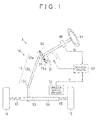
- an electric power steering system 1 includes a steering mechanism 10, an assist mechanism 20, and a control device 30.
- the steering mechanism 10 steers steered wheels 16 based on an operation of a steering wheel 11 by the driver.
- the assist mechanism 20 applies an assist force to the steering mechanism 10 by a motor 21.
- the control device 30 controls driving of the motor 21.
- the control device 30 corresponds to an arithmetic unit of the present invention.
- the steering mechanism 10 has a steering shaft 12 coupled to the steering wheel 11.
- the steering shaft 12 is formed by coupling a column shaft 12a, an intermediate shaft 12b, and a pinion shaft 12c in this order from the steering wheel 11 side.
- the lower end of the pinion shaft 12c is coupled to a rack shaft 14 via a rack and pinion mechanism 13.
- the steering shaft 12 of the steering mechanism 10 is rotated according to the operation of the steering wheel 11 by the driver, the rotary motion of the steering shaft 12 is converted to an axial reciprocating linear motion of the rack shaft 14 via the rack and pinion mechanism 13.
- This axial reciprocating linear motion of the rack shaft 14 is transmitted to the steered wheels 16 via tie rods 15 coupled to both ends of the rack shaft 14.
- the steered angle of the steered wheels 16 is thus changed and the traveling direction of a vehicle is changed.
- the assist mechanism 20 includes the motor 21 and a speed reducer 22.
- the speed reducer 22 reduces the rotational speed of an output shaft 21a of the motor 21 and transmits the resultant rotation to the column shaft 12a.
- the assist mechanism 20 transmits the rotation of the output shaft 21 a of the motor 21 to the column shaft 12a via the speed reducer 22 to apply an assist force (assist torque) to the steering shaft 12.
- the electric power steering system 1 is provided with various sensors that detect the state quantity of the vehicle and the amount of operation by the driver.
- the steering shaft 12 is provided with a torque sensor 40 that detects steering torque Th applied to the steering shaft 12 when the driver performs a steering operation.
- the vehicle is provided with a vehicle speed sensor 31 that detects a vehicle speed V as a traveling speed of the vehicle.
- the outputs of the sensors 31, 40 are transmitted to the control device 30.
- the control device 30 computes a current command value based on the steering torque Th and the vehicle speed V which are detected by the sensors 31, 40.
- the current command value is a target value of a current that is supplied to the motor 21.
- the control device 30 controls driving of the motor 21 by performing current feedback control of causing the value of a current that is supplied to the motor 21 to follow the current command value.
- the control device 30 and the torque sensor 40 form a sensor system.
- the column shaft 12a is formed by coupling an input shaft 12d, a torsion bar 12e, and a lower shaft 12f on the same axis m.
- the input shaft 12d is coupled to the steering wheel 11.
- the lower shaft 12f is coupled to the intermediate shaft 12b. Accordingly, when the driver operates the steering wheel 11 and the steering torque Th applied to the input shaft 12d is transmitted to the lower shaft 12f via the torsion bar 12e, the torsion bar 12e is torsionally deformed. At this time, a relative rotational displacement occurs between the input shaft 12d and the lower shaft 12f according to the steering torque Th.
- the torque sensor 40 includes a cylindrical holding member 41, an annular first yoke 42a, an annular second yoke 42b, an annular first magnetic flux collecting ring 43a, and an annular second magnetic flux collecting ring 43b, and a sensor IC 44.
- the holding member 41 is fixed to the outer periphery of the lower end of the input shaft 12d.
- the holding member 41 thus rotates together with the input shaft 12d.
- a multipolar magnet 41a is disposed in the outer peripheral portion of the holding member 41.
- the multipolar magnet 41a is structured so that north poles and south poles are alternately arranged in the circumferential direction of the holding member 41.
- the first yoke 42a and the second yoke 42b are disposed around the holding member 41 with predetermined clearance between each yoke 42a, 42b and the holding member 41.
- the yokes 42a, 42b are fixed to the lower shaft 12f via a joint structure, not shown.
- the yokes 42a, 42b thus rotate together with the lower shaft 12f.
- the yokes 42a, 42b are disposed so as to face each other with predetermined clearance therebetween in the direction of the axis m.
- the first yoke 42a has a plurality of pawls 45a formed on its inner peripheral surface such that the pawls 45a extend toward the second yoke 42b.
- the second yoke 42b has a plurality of pawls 45b formed on its inner peripheral surface such that the pawls 45b extend toward the first yoke 42a.
- FIG. 3 is a development view of the holding member 41 and the yokes 42a, 42b on a plane. As shown in FIG. 3 , the pawls 45a, 45b of the first and second yokes 42a, 42b are alternately arranged in the circumferential direction and face the multipolar magnet 41 a with the predetermined clearance therebetween.
- the first magnetic flux collecting ring 43a is disposed around the first yoke 42a with predetermined clearance therebetween.
- the second magnetic flux collecting ring 43b is disposed around the second yoke 42b with predetermined clearance therebetween.
- Each of the magnetic flux collecting rings 43a, 43b is made of a magnetic material.
- the first magnetic flux collecting ring 43a has a magnetic flux collecting part 46a
- the second magnetic flux collecting ring 43b has a magnetic flux collecting part 46b.
- the magnetic flux collecting parts 46a, 46b are disposed so as to face each other with predetermined clearance therebetween in the direction of the axis m.
- a magnetic circuit 47 is formed by the multipolar magnet 41a, the yokes 42a, 42b, and the magnetic flux collecting rings 43a, 43b.
- the sensor IC 44 is disposed between the magnetic flux collecting parts 46a, 46b.
- the sensor IC 44 is mainly formed by a Hall element, and outputs a detection signal Sd according to the strength of a magnetic flux (magnetic field) applied thereto.
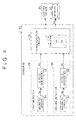
- the sensor IC 44 includes a first detector 50, a second detector 60, and a communication circuit 70.
- the first detector 50 has a magnetic sensor 51, and an analog-to-digital (A-to-D) converter 52 serving as a signal processing circuit.
- the magnetic sensor 51 is formed by a Hall element.
- the magnetic sensor 51 detects the strength of a magnetic flux applied thereto and outputs an analog value Aa according to the detected strength of the magnetic flux to the A-to-D converter 52.
- the A-to-D converter 52 generates a first digital value Da by quantizing the analog value Aa received from the magnetic sensor 51 to a predetermined number of bits, and outputs the generated first digital value Da to the communication circuit 70.
- the first digital value Da of the present embodiment is a 13-bit digital value.
- Da(0) to Da(12) represent bit information data of the first digital value Da sequentially from the most significant bit.
- the second detector 60 has the same configuration as the first detector 50. That is, the second detector 60 has a magnetic sensor 61 and an A-to-D converter 62.
- the magnetic sensor 61 outputs an analog value Ab according to the strength of a magnetic flux applied thereto.
- the A-to-D converter 62 converts the analog value Ab received from the magnetic sensor 61 to a second digital value Db.
- the first digital value Da and the second digital value Db are substantially the same value.
- Db(0) to Db(12) represent bit information data of the second digital value Db sequentially from the most significant bit.
- the communication circuit 70 generates a detection signal Sd based on a transmission request from the control device 30 and transmits the detection signal Sd to the control device 30.
- a communication target of the communication circuit 70 of the present embodiment is therefore the control device 30.
- the transmission period of the detection signal Sd is set to, e.g., a period shorter than 500 ⁇ s.
- the detection signal Sd includes the first digital value Da, the second digital value Db, a first counter value Ca, a second counter value Cb, and an error-detecting code Edc.
- a CRC value for a cyclic redundancy check (CRC), a parity bit for a parity check, etc. are used as the error-detecting code Edc.
- the first counter value Ca and the second counter value Cb are set as follows.
- the communication circuit 70 has a counter 71.
- the communication circuit 70 increments or increases the first counter value Ca of the counter 71 every time it transmits the detection signal Sd including the first digital value Da to the control device 30.
- the communication circuit 70 increments the second counter value Cb of the counter 71 every time it transmits the detection signal Sd including the second digital value Db to the control device 30.
- Each of the first counter value Ca and the second counter value Cb is comprised of, e.g., two-bit information, and changes in order of 00, 01, 10, 11, 00, 01, ... every time it is incremented.
- the configuration of the detection signal Sd is formed by four frames F1 to F4.
- the frames F1 to F4 have the same configuration.
- Each frame F1 to F4 includes a start bit, data bits, and a parity bit in this order from the head.
- the data bits are nine-bit information.
- FIG. 5 shows the configuration of the data bits in each frame F1 to F4.
- D0 to D8 represent the data bits of each frame F1 to F4 from the start bit side.
- bit information data Da(8) to Da(0) out of the bit information of the first digital value Da is sequentially placed in the data bits D0 to D8 of the first frame F1.
- Four-bit bit information data Db(3) to Db(0) out of the bit information of the second digital value Db is sequentially placed in the data bits D0 to D3 of the second frame F2.
- Four-bit bit information data Da(12) to Da(9) out of the bit information of the first digital value Da is sequentially placed in the data bits D4 to D7 of the second frame F2.
- Bit information Id is placed in the data bit D8 of the second frame F2.
- the bit information Id is used in order to identify sensor ICs in the case where there are a plurality of sensor ICs.
- the communication circuit 70 thus forms the first to third frames F1 to F3 such that the data bits of the first digital value Da and the second digital value Db placed in the frames F1 to F3 are arranged in different orders between the first digital value Da and the second digital value Db.
- the control device 30 performs processing shown in FIG. 6 in response to the detection signal Sd from the sensor IC 44. That is, the control device 30 first obtains information included in the detection signal Sd (S1) and then performs an error detection process based on the error-detecting code Edc (S2) to determine if the bit information of the detection signal Sd is normal (S3).
- the control device 30 detects abnormality (S8). For example, in this case, the control device 30 discards the received detection signal Sd and continues drive control of the motor 21 based on the previous detection signal Sd.
- the control device 30 If the bit information of the detection signal Sd is normal (S3: YES), the control device 30 reads the previous values of the counter values Ca, Cb from a memory 32 and then determines if the current values of the counter values Ca, Cb vary from the previous values thereof (S4). If the current value of the first counter value Ca does not vary from the previous value thereof (S4: NO), the control device 30 detects Abnormality (S8). Specifically, the control device 30 determines that the communication circuit 70 has fixing abnormality of the first digital value Da, namely such abnormality that it continues to transmit the same digital value as the first digital value Da. The reason for this will be described in detail later.
- the control device 30 detects abnormality (S8). If such fixing abnormality occurs that the counter values Ca, Cb do not change, the digital values Da, Db may be abnormal values. The control device 30 therefore performs fail-safe control such as stopping drive control of the motor 21.
- the control device 30 stores the current values of the counter values Ca, Cb as the previous values in the memory 32 (S5).
- the control device 30 determines if the absolute value of the deviation between the first and second digital values Da, Db is smaller than a threshold (S6).
- the absolute value of the deviation between the first and second digital values Da, Db in the case where both the first and second detectors 50, 60 are normal is measured in advance by experiments etc., and the threshold is set in advance based on the measurement result. For example, the threshold is set to a value that is larger than the maximum value of the absolute value of the deviation obtained by the measurement result by a predetermined value.
- the control device 30 detects abnormality (S8). In this case, at least one of the first and second detectors 50, 60 may have abnormality. The control device 30 therefore performs fail-safe control such as stopping drive control of the motor 21.
- the control device 30 determines that both the first and second detectors 50, 60 are normal, and computes the steering torque Th based on at least one of the first and second digital values Da, Db (S7). For example, the control device 30 computes the strength of the magnetic flux based on the first digital value Da, and computes the torsion angle of the torsion bar 12e based on the computed strength of the magnetic flux by using a map. The control device 30 also computes the steering torque Th by computation such as multiplying the computed torsion angle by the spring constant of the torsion bar 12e.
- the sensor IC 44 and the torque sensor 40 according to the present embodiment can provide the following functions and effects.
- the control device 30 can similarly detect the abnormality of the communication circuit 70. Abnormality of the sensor IC 44 can thus be more accurately detected. As a result, abnormality of the torque sensor 40 can be more accurately detected.
- the control device 30 can determine if fixing abnormality of the digital values Da, Db included in the detection signal Sd has occurred or not by monitoring if the counter values Ca, Cb included in the detection signal Sd have changed. Abnormality of the sensor IC 44 can therefore be more accurately detected.
- the control device 30 can detect an error in the bit information of the digital values Da, Db and the counter values Ca, Cb in the first to fourth frames F1 to F4 based on the error-detecting code Edc in the fourth frame F4. This can improve accuracy of communication between the sensor IC 44 and the control device 30.
- the torque sensor 40 capable of more accurately detecting abnormality of the sensor IC 44 is mounted on the electric power steering system 1. This can avoid malfunction of the electric power steering system 1.
- the present invention may also be carried out in the following other forms.
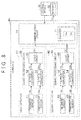
- Magnetic characteristics of the multipolar magnet 41 a and output characteristics of the magnetic sensors 51, 61 tend to change according to the ambient temperature. It is therefore effective to use the configuration as shown in FIG. 8 for the first and second detectors 50, 60. That is, the first detector 50 further includes a temperature sensor 53, an A-to-D converter 54, and a logic circuit 55.
- the temperature sensor 53 detects the ambient temperature and outputs an analog value Ata according to the detected ambient temperature.
- the A-to-D converter 54 converts the analog value Ata received from the temperature sensor 53 to a temperature digital value Dta.
- the logic circuit 55 performs temperature compensation of the first digital value Da based on the temperature digital value Dta and outputs the resultant first digital value Da' to the communication circuit 70.
- the A-to-D converters 52, 54 and the logic circuit 55 form a signal processing circuit 56 of the first detector 50.
- the second detector 60 further includes a temperature sensor 63, an A-to-D converter 64, and a logic circuit 65.
- the temperature sensor 63 outputs an analog value Atb according to the ambient temperature.
- the A-to-D converter 64 converts the analog value Atb to a temperature digital value Dtb.
- the logic circuit 65 performs temperature compensation of the second digital value Db based on the temperature digital value Dtb and outputs the resultant second digital value Db' to the communication circuit 70.
- the A-to-D converters 62, 64 and the logic circuit 65 form a signal processing circuit 66 of the second detector 60.
- the communication circuit 70 generates the detection signal Sd based on the first digital value Da' and the second digital value Db'.
- control device 30 computes the torsion angle of the torsion bar 12e based on the temperature-compensated first and second digital values Da', Db'. Accordingly, a more accurate torsion angle can be computed, and the steering torque Th can be more accurately detected.
- the configuration of the signal processing circuits 56, 66 in FIG. 8 can be modified as appropriate.
- the signal processing circuits 56, 66 may be formed by a digital signal processor (DSP).
- DSP digital signal processor
- the number of bits of the first and second digital values Da, Db is not limited to 13 bits, but may be changed as appropriate.
- the number of detectors included in the sensor IC 44 is not limited to two, but may be three or more.
- the number of digital values included in the detection signal Sd may be changed as appropriate according to the number of detectors.
- the configuration of the frames F1 to F4 of the detection signal Sd is not limited to that shown in FIG. 5 , but may be modified as appropriate.
- the number of frames of the detection signal Sd is not limited to four, but may be changed as appropriate.
- the communication circuit 70 may have any configuration which transmits a plurality of digital values in a plurality of frames and which forms the frames such that bit information data of the plurality of digital values placed in the plurality of frames is arranged in different orders between or among the plurality of digital values.
- the communication circuit 70 of the above embodiment uses the first counter value Ca and the second counter value Cb for the first digital value Da and the second digital value Db. However, the communication circuit 70 may use only one counter value. That is, the communication circuit 70 increments a single counter value every time it transmits the detection signal Sd including the first digital value Da and the second digital value Db. The communication circuit 70 may include this counter value in the detection signal Sd instead of the first and second counter values Ca, Cb of the above embodiment.
- the communication circuit 70 may have a configuration that does not use the first and second counter values Ca, Cb. That is, the first and second counter values Ca, Cb may be eliminated from the detection signal Sd. In this case, the counter 71 can be eliminated from the communication circuit 70, whereby the configuration of the communication circuit 70 can be simplified.
- the communication circuit 70 may use an error-correcting code instead of the error-detecting code Edc.
- the communication target of the communication circuit 70 is not limited to the control device 30 of the electric power steering system 1. Any device may be used as the communication target of the communication circuit 70.
- the configuration of the torque sensor 40 may be modified as appropriate.
- the position of the torsion bar 12e is not limited to the column shaft 12a, but may be changed to any position in the steering shaft 12.
- the structure of the magnetic circuit 47 may also be modified as appropriate.
- the control device 30 may be included in the torque sensor 40 of the above embodiment.
- the configuration of the sensor IC 44 of the above embodiment is not limited to the sensor IC of the torque sensor, but may be applied to a sensor IC of an appropriate sensor device such as a sensor IC of a rotation angle sensor.
- each detector of the sensor IC may include, e.g., a magneto-resistive (MR) sensor that outputs an analog value according to the direction of a magnetic flux applied thereto, a sensor that detects a physical quantity other than a magnetic flux, etc., instead of the magnetic sensor formed by the Hall element.
- MR magneto-resistive
- a sensor IC includes a plurality of detectors that detect the same physical quantity of the same detection target and outputs a digital value according to the detected physical quantity, and a communication circuit that transmits the plurality of digital values received from the plurality of detectors to a communication target.
Landscapes
- Physics & Mathematics (AREA)
- General Physics & Mathematics (AREA)
- Engineering & Computer Science (AREA)
- Computer Networks & Wireless Communication (AREA)
- Transportation (AREA)
- Combustion & Propulsion (AREA)
- Chemical & Material Sciences (AREA)
- Mechanical Engineering (AREA)
- Electromagnetism (AREA)
- Power Steering Mechanism (AREA)
- Arrangements For Transmission Of Measured Signals (AREA)
- Steering Control In Accordance With Driving Conditions (AREA)
- Measurement Of Length, Angles, Or The Like Using Electric Or Magnetic Means (AREA)
Abstract
Description
- The present invention relates to sensor systems.
- An example of sensor systems is a sensor system using a sensor integrated circuit (IC) described in Japanese Patent No.
5474018 JP 5474018 B2 JP 5474018 B2 - By using the sensor IC described in
JP 5474018 B2 - It is one object of the present invention to provide a sensor system capable of more accurately detecting abnormality.
- According to one aspect of the present invention, a sensor system includes: a plurality of detectors that detect the same physical quantity of the same detection target and output a digital value according to the detected physical quantity; a communication circuit that transmits a plurality of the digital values received from the plurality of detectors; and an arithmetic unit that receives the digital values from the communication circuit; wherein, the communication circuit places the plurality of the digital values in a plurality of frames to transmit the plurality of frames, and forms the plurality of frames such that bit information data of the plurality of digital values placed in the plurality of frames is arranged in different orders between or among the plurality of the digital values.
- With this configuration, if the communication circuit has such abnormality that a predetermined data bit of each frame is fixed to zero or one, the digital values are completely different values. The arithmetic unit can therefore detect the abnormality of the communication circuit as the digital values are different from each other as a result of comparison.
- In the sensor system of the above aspect, the plurality of frames may include counter values that changes every time the plurality of frames including the plurality of the digital values are transmitted from the communication circuit to the arithmetic unit.
- With this configuration, the arithmetic unit can determine if the communication circuit has "fixing abnormality" of the digital values included in the frames, namely such abnormality that the communication circuit continues to transmit the same digital values, or not by monitoring if the counter value included in the frames has changed.
- In the sensor system of the above aspect, the counter values may be set for each of the plurality of the digital values. With this configuration, the arithmetic unit can individually detect fixing abnormality of the digital values included in the frames by monitoring if each of the counter values for the digital values has changed. Accordingly, abnormality of the sensor system can be more accurately detected. In the sensor system of the above aspect, the arithmetic unit may calculate an absolute value of a deviation of the plurality of the digital values according to the detected physical quantity, and may determine that there is abnormality if the absolute value is equal to or larger than a predetermined threshold.
- The sensor system of the above aspect may further include: at least one temperature detector; and a plurality of correction circuits; wherein, the correction circuit may perform temperature compensation of the digital values according to the same physical quantity of the same detection target which are received from the plurality of detectors, based on an output of the temperature detector, and the communication circuit may transmit the temperature-compensated digital values. In the sensor system of the above aspect, the communication circuit may generate an error-detecting code or an error-correcting code based on the bit information data included in the plurality of frames, and the error-detecting code or the error-correcting code may be included in the plurality of frames.
- In the sensor system of the above aspect, the physical quantity of the detection target may be steering torque that is applied to a steering shaft of a vehicle, wherein, the sensor system may further include: a torsion bar that is provided at an intermediate position in the steering shaft of the vehicle; a plurality of detectors that output a digital value according to a magnetic flux applied thereto; a magnetic circuit that changes the magnetic flux applied to the plurality of detectors according to a torsion angle of the torsion bar; a communication circuit that transmits a plurality of the digital values received from the plurality of detectors; and an arithmetic unit that receives the digital values from the communication circuit and computes torque that is applied to the torsion bar based on the received digital values, the plurality of detectors may include a magnetic sensor that detects a magnetic flux applied thereto and outputs an analog value according to the detected magnetic flux, and a signal processing circuit that generates a digital value based on the analog value received from the magnetic sensor, and the communication circuit may place the plurality of the digital values in a plurality of frames to transmit the plurality of frames, and may form the plurality of frames such that bit information data of the plurality of the digital values placed in the plurality of frames is arranged in different orders between or among the plurality of the digital values.
- In the sensor system of the above aspect, the detection target may be an electric power steering system, and the physical quantity may be the steering torque that is applied to the steering shaft.
- The foregoing and further features and advantages of the invention will become apparent from the following description of example embodiments with reference to the accompanying drawings, wherein like numerals are used to represent like elements and wherein:
-
FIG. 1 is a block diagram showing the general structure of an electric power steering system; -
FIG. 2 is an exploded perspective view showing the structure of a sensor system according to an embodiment of the present invention; -
FIG. 3 is a development view of yokes and a holding member of the sensor system according to the embodiment on a plane; -
FIG. 4 is a block diagram showing the configuration of a sensor IC in the sensor system according to the embodiment; -
FIG. 5 is a table showing an example of the frame configuration of a detection signal of the sensor system according to the embodiment; -
FIG. 6 is a flowchart illustrating processing that is performed by a control device of the sensor system according to the embodiment in response to the detection signal; -
FIG. 7 is a table showing an example of the frame configuration of the detection signal in the case where a communication circuit of the sensor system according to the embodiment has abnormality; and -
FIG. 8 is a block diagram showing the configuration of a sensor IC in a sensor system according to another embodiment. - An embodiment of the present invention which is mounted on an electric power steering system will be described below. First, the electric power steering system will be roughly described. As shown in
FIG. 1 , an electricpower steering system 1 includes asteering mechanism 10, anassist mechanism 20, and acontrol device 30. Thesteering mechanism 10 steers steeredwheels 16 based on an operation of asteering wheel 11 by the driver. Theassist mechanism 20 applies an assist force to thesteering mechanism 10 by amotor 21. Thecontrol device 30 controls driving of themotor 21. Thecontrol device 30 corresponds to an arithmetic unit of the present invention. - The
steering mechanism 10 has asteering shaft 12 coupled to thesteering wheel 11. Thesteering shaft 12 is formed by coupling acolumn shaft 12a, anintermediate shaft 12b, and apinion shaft 12c in this order from thesteering wheel 11 side. The lower end of thepinion shaft 12c is coupled to arack shaft 14 via a rack andpinion mechanism 13. When thesteering shaft 12 of thesteering mechanism 10 is rotated according to the operation of thesteering wheel 11 by the driver, the rotary motion of thesteering shaft 12 is converted to an axial reciprocating linear motion of therack shaft 14 via the rack andpinion mechanism 13. This axial reciprocating linear motion of therack shaft 14 is transmitted to the steeredwheels 16 viatie rods 15 coupled to both ends of therack shaft 14. The steered angle of the steeredwheels 16 is thus changed and the traveling direction of a vehicle is changed. - The
assist mechanism 20 includes themotor 21 and aspeed reducer 22. Thespeed reducer 22 reduces the rotational speed of anoutput shaft 21a of themotor 21 and transmits the resultant rotation to thecolumn shaft 12a. Theassist mechanism 20 transmits the rotation of theoutput shaft 21 a of themotor 21 to thecolumn shaft 12a via thespeed reducer 22 to apply an assist force (assist torque) to thesteering shaft 12. - The electric
power steering system 1 is provided with various sensors that detect the state quantity of the vehicle and the amount of operation by the driver. For example, thesteering shaft 12 is provided with atorque sensor 40 that detects steering torque Th applied to thesteering shaft 12 when the driver performs a steering operation. The vehicle is provided with avehicle speed sensor 31 that detects a vehicle speed V as a traveling speed of the vehicle. The outputs of thesensors control device 30. Thecontrol device 30 computes a current command value based on the steering torque Th and the vehicle speed V which are detected by thesensors motor 21. Thecontrol device 30 controls driving of themotor 21 by performing current feedback control of causing the value of a current that is supplied to themotor 21 to follow the current command value. Thecontrol device 30 and thetorque sensor 40 form a sensor system. - The structure of the
torque sensor 40 will be described in detail below. As shown inFIG. 2 , thecolumn shaft 12a is formed by coupling aninput shaft 12d, atorsion bar 12e, and alower shaft 12f on the same axis m. Theinput shaft 12d is coupled to thesteering wheel 11. Thelower shaft 12f is coupled to theintermediate shaft 12b. Accordingly, when the driver operates thesteering wheel 11 and the steering torque Th applied to theinput shaft 12d is transmitted to thelower shaft 12f via thetorsion bar 12e, thetorsion bar 12e is torsionally deformed. At this time, a relative rotational displacement occurs between theinput shaft 12d and thelower shaft 12f according to the steering torque Th. - The
torque sensor 40 includes a cylindrical holdingmember 41, an annularfirst yoke 42a, an annularsecond yoke 42b, an annular first magneticflux collecting ring 43a, and an annular second magneticflux collecting ring 43b, and asensor IC 44. - The holding
member 41 is fixed to the outer periphery of the lower end of theinput shaft 12d. The holdingmember 41 thus rotates together with theinput shaft 12d. Amultipolar magnet 41a is disposed in the outer peripheral portion of the holdingmember 41. Themultipolar magnet 41a is structured so that north poles and south poles are alternately arranged in the circumferential direction of the holdingmember 41. - The
first yoke 42a and thesecond yoke 42b are disposed around the holdingmember 41 with predetermined clearance between eachyoke member 41. Theyokes lower shaft 12f via a joint structure, not shown. Theyokes lower shaft 12f. Theyokes first yoke 42a has a plurality ofpawls 45a formed on its inner peripheral surface such that thepawls 45a extend toward thesecond yoke 42b. Thesecond yoke 42b has a plurality ofpawls 45b formed on its inner peripheral surface such that thepawls 45b extend toward thefirst yoke 42a.FIG. 3 is a development view of the holdingmember 41 and theyokes FIG. 3 , thepawls second yokes multipolar magnet 41 a with the predetermined clearance therebetween. - The first magnetic
flux collecting ring 43a is disposed around thefirst yoke 42a with predetermined clearance therebetween. The second magneticflux collecting ring 43b is disposed around thesecond yoke 42b with predetermined clearance therebetween. Each of the magneticflux collecting rings flux collecting ring 43a has a magneticflux collecting part 46a, and the second magneticflux collecting ring 43b has a magneticflux collecting part 46b. The magneticflux collecting parts magnetic circuit 47 is formed by themultipolar magnet 41a, theyokes flux collecting rings - The
sensor IC 44 is disposed between the magneticflux collecting parts sensor IC 44 is mainly formed by a Hall element, and outputs a detection signal Sd according to the strength of a magnetic flux (magnetic field) applied thereto. - When a relative rotational displacement occurs between the
input shaft 12d and thelower shaft 12f according to the steering torque Th applied to theinput shaft 12d, the positional relationship between the holdingmember 41 and eachyoke torque sensor 40 changes and the magnetic flux collected by eachyoke sensor IC 44 changes accordingly. The detection signal Sd that is output from thesensor IC 44 is therefore a signal that changes according to the torsion angle of thetorsion bar 12e. - The electric configuration of the
sensor IC 44 will be described below. As shown inFIG. 4 , thesensor IC 44 includes afirst detector 50, asecond detector 60, and acommunication circuit 70. - The
first detector 50 has amagnetic sensor 51, and an analog-to-digital (A-to-D)converter 52 serving as a signal processing circuit. Themagnetic sensor 51 is formed by a Hall element. Themagnetic sensor 51 detects the strength of a magnetic flux applied thereto and outputs an analog value Aa according to the detected strength of the magnetic flux to the A-to-D converter 52. The A-to-D converter 52 generates a first digital value Da by quantizing the analog value Aa received from themagnetic sensor 51 to a predetermined number of bits, and outputs the generated first digital value Da to thecommunication circuit 70. The first digital value Da of the present embodiment is a 13-bit digital value. As used herein, Da(0) to Da(12) represent bit information data of the first digital value Da sequentially from the most significant bit. - The
second detector 60 has the same configuration as thefirst detector 50. That is, thesecond detector 60 has amagnetic sensor 61 and an A-to-D converter 62. Themagnetic sensor 61 outputs an analog value Ab according to the strength of a magnetic flux applied thereto. The A-to-D converter 62 converts the analog value Ab received from themagnetic sensor 61 to a second digital value Db. In the case where both thefirst detector 50 and thesecond detector 60 are normal, the first digital value Da and the second digital value Db are substantially the same value. As used herein, Db(0) to Db(12) represent bit information data of the second digital value Db sequentially from the most significant bit. - The
communication circuit 70 generates a detection signal Sd based on a transmission request from thecontrol device 30 and transmits the detection signal Sd to thecontrol device 30. A communication target of thecommunication circuit 70 of the present embodiment is therefore thecontrol device 30. The transmission period of the detection signal Sd is set to, e.g., a period shorter than 500 µs. The detection signal Sd includes the first digital value Da, the second digital value Db, a first counter value Ca, a second counter value Cb, and an error-detecting code Edc. For example, a CRC value for a cyclic redundancy check (CRC), a parity bit for a parity check, etc. are used as the error-detecting code Edc. The first counter value Ca and the second counter value Cb are set as follows. - The
communication circuit 70 has acounter 71. Thecommunication circuit 70 increments or increases the first counter value Ca of thecounter 71 every time it transmits the detection signal Sd including the first digital value Da to thecontrol device 30. Thecommunication circuit 70 increments the second counter value Cb of thecounter 71 every time it transmits the detection signal Sd including the second digital value Db to thecontrol device 30. Each of the first counter value Ca and the second counter value Cb is comprised of, e.g., two-bit information, and changes in order of 00, 01, 10, 11, 00, 01, ... every time it is incremented. - The configuration of the detection signal Sd will be described in detail below. The detection signal Sd is formed by four frames F1 to F4. The frames F1 to F4 have the same configuration. Each frame F1 to F4 includes a start bit, data bits, and a parity bit in this order from the head. The data bits are nine-bit information.
FIG. 5 shows the configuration of the data bits in each frame F1 to F4. InFIG. 5 , D0 to D8 represent the data bits of each frame F1 to F4 from the start bit side. - Nine-bit bit information data Da(8) to Da(0) out of the bit information of the first digital value Da is sequentially placed in the data bits D0 to D8 of the first frame F1. Four-bit bit information data Db(3) to Db(0) out of the bit information of the second digital value Db is sequentially placed in the data bits D0 to D3 of the second frame F2. Four-bit bit information data Da(12) to Da(9) out of the bit information of the first digital value Da is sequentially placed in the data bits D4 to D7 of the second frame F2. Bit information Id is placed in the data bit D8 of the second frame F2. The bit information Id is used in order to identify sensor ICs in the case where there are a plurality of sensor ICs.
- Nine-bit bit information data Db(12) to Db(4) out of the bit information of the second digital value Db is sequentially placed in the data bits D0 to D8 of the third frame F3. The first counter value Ca and the second counter value Cb are placed in the data bits D0 to D3 of the fourth frame F4. The error-detecting code Edc is placed in the data bits D4 to D8 of the fourth frame F4. The
communication circuit 70 generates the error-detecting code Edc based on the bit information included in the first to fourth frames F1 to F4. - The
communication circuit 70 thus forms the first to third frames F1 to F3 such that the data bits of the first digital value Da and the second digital value Db placed in the frames F1 to F3 are arranged in different orders between the first digital value Da and the second digital value Db. Thecontrol device 30 performs processing shown inFIG. 6 in response to the detection signal Sd from thesensor IC 44. That is, thecontrol device 30 first obtains information included in the detection signal Sd (S1) and then performs an error detection process based on the error-detecting code Edc (S2) to determine if the bit information of the detection signal Sd is normal (S3). If the bit information of the detection signal Sd is not normal, that is, if the bit information of the detection signal Sd has an error (S3: NO), thecontrol device 30 detects abnormality (S8). For example, in this case, thecontrol device 30 discards the received detection signal Sd and continues drive control of themotor 21 based on the previous detection signal Sd. - If the bit information of the detection signal Sd is normal (S3: YES), the
control device 30 reads the previous values of the counter values Ca, Cb from amemory 32 and then determines if the current values of the counter values Ca, Cb vary from the previous values thereof (S4). If the current value of the first counter value Ca does not vary from the previous value thereof (S4: NO), thecontrol device 30 detects Abnormality (S8). Specifically, thecontrol device 30 determines that thecommunication circuit 70 has fixing abnormality of the first digital value Da, namely such abnormality that it continues to transmit the same digital value as the first digital value Da. The reason for this will be described in detail later. Similarly, if the current value of the second counter value Cb does not vary from the previous value thereof (S4: NO), thecontrol device 30 detects abnormality (S8). If such fixing abnormality occurs that the counter values Ca, Cb do not change, the digital values Da, Db may be abnormal values. Thecontrol device 30 therefore performs fail-safe control such as stopping drive control of themotor 21. - If the current values of the counter values Ca, Cb vary from the previous values thereof (S4: YES), the
control device 30 stores the current values of the counter values Ca, Cb as the previous values in the memory 32 (S5). Thecontrol device 30 then determines if the absolute value of the deviation between the first and second digital values Da, Db is smaller than a threshold (S6). In the present embodiment, the absolute value of the deviation between the first and second digital values Da, Db in the case where both the first andsecond detectors control device 30 detects abnormality (S8). In this case, at least one of the first andsecond detectors control device 30 therefore performs fail-safe control such as stopping drive control of themotor 21. - If the absolute value of the deviation between the first and second digital values Da, Db is smaller than the threshold (S6: YES), the
control device 30 determines that both the first andsecond detectors control device 30 computes the strength of the magnetic flux based on the first digital value Da, and computes the torsion angle of thetorsion bar 12e based on the computed strength of the magnetic flux by using a map. Thecontrol device 30 also computes the steering torque Th by computation such as multiplying the computed torsion angle by the spring constant of thetorsion bar 12e. - The
sensor IC 44 and thetorque sensor 40 according to the present embodiment can provide the following functions and effects. - (1) As shown in
FIG. 7 , if thecommunication circuit 70 has such abnormality that the data bit D3 in each frame F1 to F4 is fixed to "1," the bit information data Da(5) of the first digital value Da is fixed to "1," and the bit information data Db(0), Db(9) of the second digital value Db is fixed to "1." At this time, the first digital value Da and the second digital value Db are completely different values. Accordingly, when thecontrol device 30 computes the deviation between the first and second digital values Da, Db in S6 ofFIG. 6 , the computed value of the deviation is equal to or larger than the threshold (S6: NO). Thecontrol device 30 can therefore detect the abnormality (S8). Even when thecommunication circuit 70 has such abnormality that a data bit other than the data bit D3 is fixed to a value, thecontrol device 30 can similarly detect the abnormality of thecommunication circuit 70. Abnormality of thesensor IC 44 can thus be more accurately detected. As a result, abnormality of thetorque sensor 40 can be more accurately detected. - (2) The
control device 30 can determine if fixing abnormality of the digital values Da, Db included in the detection signal Sd has occurred or not by monitoring if the counter values Ca, Cb included in the detection signal Sd have changed. Abnormality of thesensor IC 44 can therefore be more accurately detected. - (3) The
control device 30 can detect an error in the bit information of the digital values Da, Db and the counter values Ca, Cb in the first to fourth frames F1 to F4 based on the error-detecting code Edc in the fourth frame F4. This can improve accuracy of communication between thesensor IC 44 and thecontrol device 30. - (4) The
torque sensor 40 capable of more accurately detecting abnormality of thesensor IC 44 is mounted on the electricpower steering system 1. This can avoid malfunction of the electricpower steering system 1. - The present invention may also be carried out in the following other forms. Magnetic characteristics of the
multipolar magnet 41 a and output characteristics of themagnetic sensors FIG. 8 for the first andsecond detectors first detector 50 further includes atemperature sensor 53, an A-to-D converter 54, and alogic circuit 55. Thetemperature sensor 53 detects the ambient temperature and outputs an analog value Ata according to the detected ambient temperature. The A-to-D converter 54 converts the analog value Ata received from thetemperature sensor 53 to a temperature digital value Dta. Thelogic circuit 55 performs temperature compensation of the first digital value Da based on the temperature digital value Dta and outputs the resultant first digital value Da' to thecommunication circuit 70. The A-to-D converters logic circuit 55 form asignal processing circuit 56 of thefirst detector 50. - Like the
first detector 50, thesecond detector 60 further includes atemperature sensor 63, an A-to-D converter 64, and alogic circuit 65. Thetemperature sensor 63 outputs an analog value Atb according to the ambient temperature. The A-to-D converter 64 converts the analog value Atb to a temperature digital value Dtb. Thelogic circuit 65 performs temperature compensation of the second digital value Db based on the temperature digital value Dtb and outputs the resultant second digital value Db' to thecommunication circuit 70. The A-to-D converters logic circuit 65 form asignal processing circuit 66 of thesecond detector 60. Thecommunication circuit 70 generates the detection signal Sd based on the first digital value Da' and the second digital value Db'. In this configuration, thecontrol device 30 computes the torsion angle of thetorsion bar 12e based on the temperature-compensated first and second digital values Da', Db'. Accordingly, a more accurate torsion angle can be computed, and the steering torque Th can be more accurately detected. - The configuration of the
signal processing circuits FIG. 8 can be modified as appropriate. For example, thesignal processing circuits - The number of detectors included in the
sensor IC 44 is not limited to two, but may be three or more. The number of digital values included in the detection signal Sd may be changed as appropriate according to the number of detectors. The configuration of the frames F1 to F4 of the detection signal Sd is not limited to that shown inFIG. 5 , but may be modified as appropriate. The number of frames of the detection signal Sd is not limited to four, but may be changed as appropriate. In other words, thecommunication circuit 70 may have any configuration which transmits a plurality of digital values in a plurality of frames and which forms the frames such that bit information data of the plurality of digital values placed in the plurality of frames is arranged in different orders between or among the plurality of digital values. - The
communication circuit 70 of the above embodiment uses the first counter value Ca and the second counter value Cb for the first digital value Da and the second digital value Db. However, thecommunication circuit 70 may use only one counter value. That is, thecommunication circuit 70 increments a single counter value every time it transmits the detection signal Sd including the first digital value Da and the second digital value Db. Thecommunication circuit 70 may include this counter value in the detection signal Sd instead of the first and second counter values Ca, Cb of the above embodiment. - The
communication circuit 70 may have a configuration that does not use the first and second counter values Ca, Cb. That is, the first and second counter values Ca, Cb may be eliminated from the detection signal Sd. In this case, thecounter 71 can be eliminated from thecommunication circuit 70, whereby the configuration of thecommunication circuit 70 can be simplified. - The
communication circuit 70 may use an error-correcting code instead of the error-detecting code Edc. The communication target of thecommunication circuit 70 is not limited to thecontrol device 30 of the electricpower steering system 1. Any device may be used as the communication target of thecommunication circuit 70. - The configuration of the
torque sensor 40 may be modified as appropriate. For example, the position of thetorsion bar 12e is not limited to thecolumn shaft 12a, but may be changed to any position in the steeringshaft 12. The structure of themagnetic circuit 47 may also be modified as appropriate. - The
control device 30 may be included in thetorque sensor 40 of the above embodiment. The configuration of thesensor IC 44 of the above embodiment is not limited to the sensor IC of the torque sensor, but may be applied to a sensor IC of an appropriate sensor device such as a sensor IC of a rotation angle sensor. In this case, each detector of the sensor IC may include, e.g., a magneto-resistive (MR) sensor that outputs an analog value according to the direction of a magnetic flux applied thereto, a sensor that detects a physical quantity other than a magnetic flux, etc., instead of the magnetic sensor formed by the Hall element. In other words, the configuration similar to thesensor IC 44 of the above embodiment can be used as long as a sensor IC includes a plurality of detectors that detect the same physical quantity of the same detection target and outputs a digital value according to the detected physical quantity, and a communication circuit that transmits the plurality of digital values received from the plurality of detectors to a communication target.
Claims (8)
- A sensor system, comprising:a plurality of detectors that detect the same physical quantity of the same detection target and output a digital value according to the detected physical quantity;a communication circuit that transmits a plurality of the digital values received from the plurality of detectors; andan arithmetic unit that receives the digital values from the communication circuit; wherein,the communication circuit places the plurality of the digital values in a plurality of frames to transmit the plurality of frames, and forms the plurality of frames such that bit information data of the plurality of the digital values placed in the plurality of frames is arranged in different orders between or among the plurality of the digital values.
- The sensor system according to claim 1, wherein,
the plurality of frames include counter values that changes every time the plurality of frames including the plurality of the digital values are transmitted from the communication circuit to the arithmetic unit. - The sensor system according to claim 2, wherein,
the counter values are set for each of the plurality of the digital values. - The sensor system according to claim 1, wherein,
the arithmetic unit calculates an absolute value of a deviation of the plurality of the digital values according to the detected physical quantity, and determines that there is abnormality if the absolute value is equal to or larger than a predetermined threshold. - The sensor system according to claim 1, further comprising:at least one temperature detector; anda plurality of correction circuits; wherein,the correction circuit performs temperature compensation of the digital values according to the same physical quantity of the same detection target which are received from the plurality of detectors, based on an output of the temperature detector, andthe communication circuit transmits the temperature-compensated digital values.
- The sensor system according to claim 1, wherein,
the communication circuit generates an error-detecting code or an error-correcting code based on the bit information data included in the plurality of frames, and the error-detecting code or the error-correcting code is included in the plurality of frames. - The sensor system according to any one of claims 1 to 6, wherein,
the physical quantity of the detection target is steering torque that is applied to a steering shaft of a vehicle, wherein,
the sensor system further comprising:a torsion bar that is provided at an intermediate position in the steering shaft of the vehicle;a plurality of detectors that output a digital value according to a magnetic flux applied thereto;a magnetic circuit that changes the magnetic flux applied to the plurality of detectors according to a torsion angle of the torsion bar;a communication circuit that transmits a plurality of the digital values received from the plurality of detectors; andan arithmetic unit that receives the digital values from the communication circuit and computes torque that is applied to the torsion bar based on the received digital values,the plurality of detectors include a magnetic sensor that detects a magnetic flux applied thereto and outputs an analog value according to the detected magnetic flux, and a signal processing circuit that generates a digital value based on the analog value received from the magnetic sensor, andthe communication circuit places the plurality of the digital values in a plurality of frames to transmit the plurality of frames, and forms the plurality of frames such that bit information data of the plurality of the digital values placed in the plurality of frames is arranged in different orders between or among the plurality of the digital values. - The sensor system according to claim 7, wherein,
the detection target is an electric power steering system, and the physical quantity is the steering torque that is applied to the steering shaft.
Applications Claiming Priority (1)
| Application Number | Priority Date | Filing Date | Title |
|---|---|---|---|
| JP2014223146A JP6375876B2 (en) | 2014-10-31 | 2014-10-31 | Sensor system and torque sensor |
Publications (2)
| Publication Number | Publication Date |
|---|---|
| EP3015823A1 true EP3015823A1 (en) | 2016-05-04 |
| EP3015823B1 EP3015823B1 (en) | 2017-08-02 |
Family
ID=54477839
Family Applications (1)
| Application Number | Title | Priority Date | Filing Date |
|---|---|---|---|
| EP15191952.9A Not-in-force EP3015823B1 (en) | 2014-10-31 | 2015-10-28 | Sensor system |
Country Status (4)
| Country | Link |
|---|---|
| US (1) | US10234349B2 (en) |
| EP (1) | EP3015823B1 (en) |
| JP (1) | JP6375876B2 (en) |
| CN (1) | CN105571626B (en) |
Families Citing this family (4)
| Publication number | Priority date | Publication date | Assignee | Title |
|---|---|---|---|---|
| WO2018056599A1 (en) * | 2016-09-23 | 2018-03-29 | 주식회사 레티그리드 | Measurement device including multiple magnetic sensors |
| CN107776660B (en) * | 2017-10-17 | 2020-04-14 | 哈尔滨工业大学 | Torque angle sensor of automobile electric power steering system and its detection method |
| KR101883229B1 (en) * | 2018-01-15 | 2018-07-30 | 주식회사 레티그리드 | A single chip having a plurality of magnetic sensors |
| JP7234737B2 (en) * | 2019-03-28 | 2023-03-08 | 株式会社デンソー | detection unit |
Citations (4)
| Publication number | Priority date | Publication date | Assignee | Title |
|---|---|---|---|---|
| EP0180085A2 (en) * | 1984-10-31 | 1986-05-07 | Westinghouse Electric Corporation | Distributed microprocessor based sensor signal processing system for a complex process |
| WO2008021931A1 (en) * | 2006-08-11 | 2008-02-21 | Distribution Control Systems | Detection of fast poll responses in a twacs inbound receiver |
| US20120074972A1 (en) * | 2010-09-24 | 2012-03-29 | Rasbornig Friedrich | Sensor self-diagnostics using multiple signal paths |
| EP2672233A2 (en) * | 2012-06-05 | 2013-12-11 | Jtekt Corporation | Sensor device |
Family Cites Families (12)
| Publication number | Priority date | Publication date | Assignee | Title |
|---|---|---|---|---|
| JP4561318B2 (en) * | 2004-11-05 | 2010-10-13 | 日本精工株式会社 | Electric power steering device |
| JP4774740B2 (en) * | 2005-01-06 | 2011-09-14 | 株式会社ジェイテクト | Electric power steering device |
| JP2006250865A (en) * | 2005-03-14 | 2006-09-21 | Hitachi Ltd | Torque detection device and torque control device using the same |
| JP4863953B2 (en) * | 2007-08-30 | 2012-01-25 | 日立オートモティブシステムズ株式会社 | Physical quantity conversion sensor and motor control system using the same |
| DE102007063099A1 (en) * | 2007-12-28 | 2009-07-02 | Kuka Roboter Gmbh | Robot and method for monitoring the moments on such |
| US20100250184A1 (en) * | 2008-03-18 | 2010-09-30 | Satoshi Kawamura | Rotation angle detection apparatus |
| JP5789911B2 (en) * | 2009-10-06 | 2015-10-07 | 株式会社ジェイテクト | Rotation angle detection device and electric power steering device |
| JP2013205102A (en) * | 2012-03-27 | 2013-10-07 | Jtekt Corp | Torque detection device and electric power steering device including the device |
| JP5793106B2 (en) * | 2012-04-26 | 2015-10-14 | 日立オートモティブシステムズステアリング株式会社 | Power steering device and control device for power steering device |
| JP6098513B2 (en) * | 2012-10-23 | 2017-03-22 | 日本精工株式会社 | Torque detection device, electric power steering device, and vehicle |
| JP6024969B2 (en) * | 2012-12-12 | 2016-11-16 | 株式会社ジェイテクト | Rotation angle detection device and electric power steering device having the same |
| JP5974997B2 (en) * | 2013-08-28 | 2016-08-23 | 株式会社デンソー | Electronic control system |
-
2014
- 2014-10-31 JP JP2014223146A patent/JP6375876B2/en not_active Expired - Fee Related
-
2015
- 2015-10-22 US US14/920,305 patent/US10234349B2/en not_active Expired - Fee Related
- 2015-10-28 CN CN201510711480.7A patent/CN105571626B/en not_active Expired - Fee Related
- 2015-10-28 EP EP15191952.9A patent/EP3015823B1/en not_active Not-in-force
Patent Citations (6)
| Publication number | Priority date | Publication date | Assignee | Title |
|---|---|---|---|---|
| EP0180085A2 (en) * | 1984-10-31 | 1986-05-07 | Westinghouse Electric Corporation | Distributed microprocessor based sensor signal processing system for a complex process |
| WO2008021931A1 (en) * | 2006-08-11 | 2008-02-21 | Distribution Control Systems | Detection of fast poll responses in a twacs inbound receiver |
| US20120074972A1 (en) * | 2010-09-24 | 2012-03-29 | Rasbornig Friedrich | Sensor self-diagnostics using multiple signal paths |
| JP2012068248A (en) * | 2010-09-24 | 2012-04-05 | Infineon Technologies Ag | Sensor self-diagnosis using plural signal paths |
| JP5474018B2 (en) | 2010-09-24 | 2014-04-16 | インフィネオン テクノロジーズ アーゲー | Sensor self-diagnosis using multiple signal paths |
| EP2672233A2 (en) * | 2012-06-05 | 2013-12-11 | Jtekt Corporation | Sensor device |
Also Published As
| Publication number | Publication date |
|---|---|
| JP2016090331A (en) | 2016-05-23 |
| EP3015823B1 (en) | 2017-08-02 |
| CN105571626A (en) | 2016-05-11 |
| US20160123823A1 (en) | 2016-05-05 |
| JP6375876B2 (en) | 2018-08-22 |
| US10234349B2 (en) | 2019-03-19 |
| CN105571626B (en) | 2019-11-01 |
Similar Documents
| Publication | Publication Date | Title |
|---|---|---|
| JP6413384B2 (en) | Steering device | |
| US8579072B2 (en) | Electric power steering system and controller of the electric power steering system | |
| JP5126325B2 (en) | Rotation angle detection device and electric power steering device using the same | |
| EP3015823B1 (en) | Sensor system | |
| JP6597254B2 (en) | Rotation angle detector | |
| CN102564295B (en) | Rotation angle detection device and electric power steering apparatus using same | |
| JP2007010329A (en) | Rotation angle detection device and electric power steering device using the same | |
| JP6672652B2 (en) | Steering control device | |
| EP2733047B1 (en) | Steering system | |
| US8810239B2 (en) | Angle sensor | |
| JP2015098223A (en) | Sensor device and electric power steering device | |
| WO2012066942A1 (en) | Device and method for adjusting electric power steering device | |
| JP5656016B2 (en) | Vehicle steering control device | |
| JP6160298B2 (en) | Torque detection device, electric power steering device including the torque detection device, and torque detection device calibration method | |
| JP2017102019A (en) | Torque sensor unit | |
| JP2016133962A (en) | Sensor apparatus and sensor system | |
| EP3479067B1 (en) | Rotational position sensor with tunnel magnetoresistive sensor | |
| JP6409509B2 (en) | Sensor system | |
| JP2008233040A (en) | Torque detection device | |
| JP6690164B2 (en) | Communications system | |
| US8746082B2 (en) | Torque sensor | |
| CN114162214A (en) | Steering system | |
| WO2022102350A1 (en) | Rotation angle detection device | |
| CN116324360A (en) | Method and electromechanical steering system for compensating a measurement signal from a torque sensor arrangement | |
| JP2023031721A (en) | Rotation detection device |
Legal Events
| Date | Code | Title | Description |
|---|---|---|---|
| PUAI | Public reference made under article 153(3) epc to a published international application that has entered the european phase |
Free format text: ORIGINAL CODE: 0009012 |
|
| AK | Designated contracting states |
Kind code of ref document: A1 Designated state(s): AL AT BE BG CH CY CZ DE DK EE ES FI FR GB GR HR HU IE IS IT LI LT LU LV MC MK MT NL NO PL PT RO RS SE SI SK SM TR |
|
| AX | Request for extension of the european patent |
Extension state: BA ME |
|
| 17P | Request for examination filed |
Effective date: 20160919 |
|
| RBV | Designated contracting states (corrected) |
Designated state(s): AL AT BE BG CH CY CZ DE DK EE ES FI FR GB GR HR HU IE IS IT LI LT LU LV MC MK MT NL NO PL PT RO RS SE SI SK SM TR |
|
| GRAP | Despatch of communication of intention to grant a patent |
Free format text: ORIGINAL CODE: EPIDOSNIGR1 |
|
| RIC1 | Information provided on ipc code assigned before grant |
Ipc: B62D 6/10 20060101ALI20170112BHEP Ipc: G08C 25/00 20060101ALI20170112BHEP Ipc: G01D 3/08 20060101AFI20170112BHEP Ipc: H04Q 9/00 20060101ALI20170112BHEP Ipc: G01L 5/22 20060101ALI20170112BHEP Ipc: G01D 21/00 20060101ALI20170112BHEP Ipc: G01L 3/10 20060101ALI20170112BHEP |
|
| RAP1 | Party data changed (applicant data changed or rights of an application transferred) |
Owner name: JTEKT CORPORATION |
|
| INTG | Intention to grant announced |
Effective date: 20170215 |
|
| GRAS | Grant fee paid |
Free format text: ORIGINAL CODE: EPIDOSNIGR3 |
|
| GRAA | (expected) grant |
Free format text: ORIGINAL CODE: 0009210 |
|
| AK | Designated contracting states |
Kind code of ref document: B1 Designated state(s): AL AT BE BG CH CY CZ DE DK EE ES FI FR GB GR HR HU IE IS IT LI LT LU LV MC MK MT NL NO PL PT RO RS SE SI SK SM TR |
|
| REG | Reference to a national code |
Ref country code: CH Ref legal event code: EP Ref country code: AT Ref legal event code: REF Ref document number: 914967 Country of ref document: AT Kind code of ref document: T Effective date: 20170815 |
|
| REG | Reference to a national code |
Ref country code: IE Ref legal event code: FG4D |
|
| REG | Reference to a national code |
Ref country code: DE Ref legal event code: R096 Ref document number: 602015003864 Country of ref document: DE |
|
| REG | Reference to a national code |
Ref country code: FR Ref legal event code: PLFP Year of fee payment: 3 |
|
| REG | Reference to a national code |
Ref country code: NL Ref legal event code: MP Effective date: 20170802 |
|
| REG | Reference to a national code |
Ref country code: AT Ref legal event code: MK05 Ref document number: 914967 Country of ref document: AT Kind code of ref document: T Effective date: 20170802 |
|
| REG | Reference to a national code |
Ref country code: LT Ref legal event code: MG4D |
|
| PG25 | Lapsed in a contracting state [announced via postgrant information from national office to epo] |
Ref country code: NL Free format text: LAPSE BECAUSE OF FAILURE TO SUBMIT A TRANSLATION OF THE DESCRIPTION OR TO PAY THE FEE WITHIN THE PRESCRIBED TIME-LIMIT Effective date: 20170802 Ref country code: NO Free format text: LAPSE BECAUSE OF FAILURE TO SUBMIT A TRANSLATION OF THE DESCRIPTION OR TO PAY THE FEE WITHIN THE PRESCRIBED TIME-LIMIT Effective date: 20171102 Ref country code: LT Free format text: LAPSE BECAUSE OF FAILURE TO SUBMIT A TRANSLATION OF THE DESCRIPTION OR TO PAY THE FEE WITHIN THE PRESCRIBED TIME-LIMIT Effective date: 20170802 Ref country code: SE Free format text: LAPSE BECAUSE OF FAILURE TO SUBMIT A TRANSLATION OF THE DESCRIPTION OR TO PAY THE FEE WITHIN THE PRESCRIBED TIME-LIMIT Effective date: 20170802 Ref country code: FI Free format text: LAPSE BECAUSE OF FAILURE TO SUBMIT A TRANSLATION OF THE DESCRIPTION OR TO PAY THE FEE WITHIN THE PRESCRIBED TIME-LIMIT Effective date: 20170802 Ref country code: HR Free format text: LAPSE BECAUSE OF FAILURE TO SUBMIT A TRANSLATION OF THE DESCRIPTION OR TO PAY THE FEE WITHIN THE PRESCRIBED TIME-LIMIT Effective date: 20170802 Ref country code: AT Free format text: LAPSE BECAUSE OF FAILURE TO SUBMIT A TRANSLATION OF THE DESCRIPTION OR TO PAY THE FEE WITHIN THE PRESCRIBED TIME-LIMIT Effective date: 20170802 |
|
| PG25 | Lapsed in a contracting state [announced via postgrant information from national office to epo] |
Ref country code: RS Free format text: LAPSE BECAUSE OF FAILURE TO SUBMIT A TRANSLATION OF THE DESCRIPTION OR TO PAY THE FEE WITHIN THE PRESCRIBED TIME-LIMIT Effective date: 20170802 Ref country code: LV Free format text: LAPSE BECAUSE OF FAILURE TO SUBMIT A TRANSLATION OF THE DESCRIPTION OR TO PAY THE FEE WITHIN THE PRESCRIBED TIME-LIMIT Effective date: 20170802 Ref country code: ES Free format text: LAPSE BECAUSE OF FAILURE TO SUBMIT A TRANSLATION OF THE DESCRIPTION OR TO PAY THE FEE WITHIN THE PRESCRIBED TIME-LIMIT Effective date: 20170802 Ref country code: GR Free format text: LAPSE BECAUSE OF FAILURE TO SUBMIT A TRANSLATION OF THE DESCRIPTION OR TO PAY THE FEE WITHIN THE PRESCRIBED TIME-LIMIT Effective date: 20171103 Ref country code: PL Free format text: LAPSE BECAUSE OF FAILURE TO SUBMIT A TRANSLATION OF THE DESCRIPTION OR TO PAY THE FEE WITHIN THE PRESCRIBED TIME-LIMIT Effective date: 20170802 Ref country code: IS Free format text: LAPSE BECAUSE OF FAILURE TO SUBMIT A TRANSLATION OF THE DESCRIPTION OR TO PAY THE FEE WITHIN THE PRESCRIBED TIME-LIMIT Effective date: 20171202 Ref country code: BG Free format text: LAPSE BECAUSE OF FAILURE TO SUBMIT A TRANSLATION OF THE DESCRIPTION OR TO PAY THE FEE WITHIN THE PRESCRIBED TIME-LIMIT Effective date: 20171102 |
|
| PG25 | Lapsed in a contracting state [announced via postgrant information from national office to epo] |
Ref country code: RO Free format text: LAPSE BECAUSE OF FAILURE TO SUBMIT A TRANSLATION OF THE DESCRIPTION OR TO PAY THE FEE WITHIN THE PRESCRIBED TIME-LIMIT Effective date: 20170802 Ref country code: CZ Free format text: LAPSE BECAUSE OF FAILURE TO SUBMIT A TRANSLATION OF THE DESCRIPTION OR TO PAY THE FEE WITHIN THE PRESCRIBED TIME-LIMIT Effective date: 20170802 Ref country code: DK Free format text: LAPSE BECAUSE OF FAILURE TO SUBMIT A TRANSLATION OF THE DESCRIPTION OR TO PAY THE FEE WITHIN THE PRESCRIBED TIME-LIMIT Effective date: 20170802 |
|
| REG | Reference to a national code |
Ref country code: DE Ref legal event code: R097 Ref document number: 602015003864 Country of ref document: DE |
|
| PG25 | Lapsed in a contracting state [announced via postgrant information from national office to epo] |
Ref country code: EE Free format text: LAPSE BECAUSE OF FAILURE TO SUBMIT A TRANSLATION OF THE DESCRIPTION OR TO PAY THE FEE WITHIN THE PRESCRIBED TIME-LIMIT Effective date: 20170802 Ref country code: MC Free format text: LAPSE BECAUSE OF FAILURE TO SUBMIT A TRANSLATION OF THE DESCRIPTION OR TO PAY THE FEE WITHIN THE PRESCRIBED TIME-LIMIT Effective date: 20170802 Ref country code: IT Free format text: LAPSE BECAUSE OF FAILURE TO SUBMIT A TRANSLATION OF THE DESCRIPTION OR TO PAY THE FEE WITHIN THE PRESCRIBED TIME-LIMIT Effective date: 20170802 Ref country code: SM Free format text: LAPSE BECAUSE OF FAILURE TO SUBMIT A TRANSLATION OF THE DESCRIPTION OR TO PAY THE FEE WITHIN THE PRESCRIBED TIME-LIMIT Effective date: 20170802 Ref country code: SK Free format text: LAPSE BECAUSE OF FAILURE TO SUBMIT A TRANSLATION OF THE DESCRIPTION OR TO PAY THE FEE WITHIN THE PRESCRIBED TIME-LIMIT Effective date: 20170802 |
|
| PLBE | No opposition filed within time limit |
Free format text: ORIGINAL CODE: 0009261 |
|
| STAA | Information on the status of an ep patent application or granted ep patent |
Free format text: STATUS: NO OPPOSITION FILED WITHIN TIME LIMIT |
|
| 26N | No opposition filed |
Effective date: 20180503 |
|
| REG | Reference to a national code |
Ref country code: IE Ref legal event code: MM4A |
|
| PG25 | Lapsed in a contracting state [announced via postgrant information from national office to epo] |
Ref country code: LU Free format text: LAPSE BECAUSE OF NON-PAYMENT OF DUE FEES Effective date: 20171028 |
|
| REG | Reference to a national code |
Ref country code: BE Ref legal event code: MM Effective date: 20171031 |
|
| PG25 | Lapsed in a contracting state [announced via postgrant information from national office to epo] |
Ref country code: SI Free format text: LAPSE BECAUSE OF FAILURE TO SUBMIT A TRANSLATION OF THE DESCRIPTION OR TO PAY THE FEE WITHIN THE PRESCRIBED TIME-LIMIT Effective date: 20170802 Ref country code: BE Free format text: LAPSE BECAUSE OF NON-PAYMENT OF DUE FEES Effective date: 20171031 |
|
| REG | Reference to a national code |
Ref country code: FR Ref legal event code: PLFP Year of fee payment: 4 |
|
| PG25 | Lapsed in a contracting state [announced via postgrant information from national office to epo] |
Ref country code: MT Free format text: LAPSE BECAUSE OF NON-PAYMENT OF DUE FEES Effective date: 20171028 |
|
| PG25 | Lapsed in a contracting state [announced via postgrant information from national office to epo] |
Ref country code: IE Free format text: LAPSE BECAUSE OF NON-PAYMENT OF DUE FEES Effective date: 20171028 |
|
| REG | Reference to a national code |
Ref country code: CH Ref legal event code: PL |
|
| PG25 | Lapsed in a contracting state [announced via postgrant information from national office to epo] |
Ref country code: HU Free format text: LAPSE BECAUSE OF FAILURE TO SUBMIT A TRANSLATION OF THE DESCRIPTION OR TO PAY THE FEE WITHIN THE PRESCRIBED TIME-LIMIT; INVALID AB INITIO Effective date: 20151028 |
|
| PG25 | Lapsed in a contracting state [announced via postgrant information from national office to epo] |
Ref country code: CH Free format text: LAPSE BECAUSE OF NON-PAYMENT OF DUE FEES Effective date: 20181031 Ref country code: LI Free format text: LAPSE BECAUSE OF NON-PAYMENT OF DUE FEES Effective date: 20181031 |
|
| PG25 | Lapsed in a contracting state [announced via postgrant information from national office to epo] |
Ref country code: CY Free format text: LAPSE BECAUSE OF FAILURE TO SUBMIT A TRANSLATION OF THE DESCRIPTION OR TO PAY THE FEE WITHIN THE PRESCRIBED TIME-LIMIT Effective date: 20170802 |
|
| PG25 | Lapsed in a contracting state [announced via postgrant information from national office to epo] |
Ref country code: MK Free format text: LAPSE BECAUSE OF FAILURE TO SUBMIT A TRANSLATION OF THE DESCRIPTION OR TO PAY THE FEE WITHIN THE PRESCRIBED TIME-LIMIT Effective date: 20170802 |
|
| PG25 | Lapsed in a contracting state [announced via postgrant information from national office to epo] |
Ref country code: TR Free format text: LAPSE BECAUSE OF FAILURE TO SUBMIT A TRANSLATION OF THE DESCRIPTION OR TO PAY THE FEE WITHIN THE PRESCRIBED TIME-LIMIT Effective date: 20170802 |
|
| PG25 | Lapsed in a contracting state [announced via postgrant information from national office to epo] |
Ref country code: PT Free format text: LAPSE BECAUSE OF FAILURE TO SUBMIT A TRANSLATION OF THE DESCRIPTION OR TO PAY THE FEE WITHIN THE PRESCRIBED TIME-LIMIT Effective date: 20170802 |
|
| PG25 | Lapsed in a contracting state [announced via postgrant information from national office to epo] |
Ref country code: AL Free format text: LAPSE BECAUSE OF FAILURE TO SUBMIT A TRANSLATION OF THE DESCRIPTION OR TO PAY THE FEE WITHIN THE PRESCRIBED TIME-LIMIT Effective date: 20170802 |
|
| GBPC | Gb: european patent ceased through non-payment of renewal fee |
Effective date: 20191028 |
|
| PG25 | Lapsed in a contracting state [announced via postgrant information from national office to epo] |
Ref country code: GB Free format text: LAPSE BECAUSE OF NON-PAYMENT OF DUE FEES Effective date: 20191028 |
|
| PGFP | Annual fee paid to national office [announced via postgrant information from national office to epo] |
Ref country code: FR Payment date: 20200914 Year of fee payment: 6 |
|
| PGFP | Annual fee paid to national office [announced via postgrant information from national office to epo] |
Ref country code: DE Payment date: 20201013 Year of fee payment: 6 |
|
| REG | Reference to a national code |
Ref country code: DE Ref legal event code: R119 Ref document number: 602015003864 Country of ref document: DE |
|
| PG25 | Lapsed in a contracting state [announced via postgrant information from national office to epo] |
Ref country code: DE Free format text: LAPSE BECAUSE OF NON-PAYMENT OF DUE FEES Effective date: 20220503 |
|
| PG25 | Lapsed in a contracting state [announced via postgrant information from national office to epo] |
Ref country code: FR Free format text: LAPSE BECAUSE OF NON-PAYMENT OF DUE FEES Effective date: 20211031 |