EP3015735A2 - Cylindrical bearing with thermally conductive members - Google Patents
Cylindrical bearing with thermally conductive members Download PDFInfo
- Publication number
- EP3015735A2 EP3015735A2 EP15187604.2A EP15187604A EP3015735A2 EP 3015735 A2 EP3015735 A2 EP 3015735A2 EP 15187604 A EP15187604 A EP 15187604A EP 3015735 A2 EP3015735 A2 EP 3015735A2
- Authority
- EP
- European Patent Office
- Prior art keywords
- metallic
- laminae
- bearing
- lamina
- conductive member
- Prior art date
- Legal status (The legal status is an assumption and is not a legal conclusion. Google has not performed a legal analysis and makes no representation as to the accuracy of the status listed.)
- Granted
Links
Images





Classifications
-
- F—MECHANICAL ENGINEERING; LIGHTING; HEATING; WEAPONS; BLASTING
- F16—ENGINEERING ELEMENTS AND UNITS; GENERAL MEASURES FOR PRODUCING AND MAINTAINING EFFECTIVE FUNCTIONING OF MACHINES OR INSTALLATIONS; THERMAL INSULATION IN GENERAL
- F16C—SHAFTS; FLEXIBLE SHAFTS; ELEMENTS OR CRANKSHAFT MECHANISMS; ROTARY BODIES OTHER THAN GEARING ELEMENTS; BEARINGS
- F16C17/00—Sliding-contact bearings for exclusively rotary movement
- F16C17/12—Sliding-contact bearings for exclusively rotary movement characterised by features not related to the direction of the load
- F16C17/22—Sliding-contact bearings for exclusively rotary movement characterised by features not related to the direction of the load with arrangements compensating for thermal expansion
-
- B—PERFORMING OPERATIONS; TRANSPORTING
- B64—AIRCRAFT; AVIATION; COSMONAUTICS
- B64C—AEROPLANES; HELICOPTERS
- B64C27/00—Rotorcraft; Rotors peculiar thereto
- B64C27/32—Rotors
-
- F—MECHANICAL ENGINEERING; LIGHTING; HEATING; WEAPONS; BLASTING
- F16—ENGINEERING ELEMENTS AND UNITS; GENERAL MEASURES FOR PRODUCING AND MAINTAINING EFFECTIVE FUNCTIONING OF MACHINES OR INSTALLATIONS; THERMAL INSULATION IN GENERAL
- F16C—SHAFTS; FLEXIBLE SHAFTS; ELEMENTS OR CRANKSHAFT MECHANISMS; ROTARY BODIES OTHER THAN GEARING ELEMENTS; BEARINGS
- F16C27/00—Elastic or yielding bearings or bearing supports, for exclusively rotary movement
- F16C27/06—Elastic or yielding bearings or bearing supports, for exclusively rotary movement by means of parts of rubber or like materials
- F16C27/063—Sliding contact bearings
-
- F—MECHANICAL ENGINEERING; LIGHTING; HEATING; WEAPONS; BLASTING
- F16—ENGINEERING ELEMENTS AND UNITS; GENERAL MEASURES FOR PRODUCING AND MAINTAINING EFFECTIVE FUNCTIONING OF MACHINES OR INSTALLATIONS; THERMAL INSULATION IN GENERAL
- F16F—SPRINGS; SHOCK-ABSORBERS; MEANS FOR DAMPING VIBRATION
- F16F1/00—Springs
- F16F1/36—Springs made of rubber or other material having high internal friction, e.g. thermoplastic elastomers
- F16F1/38—Springs made of rubber or other material having high internal friction, e.g. thermoplastic elastomers with a sleeve of elastic material between a rigid outer sleeve and a rigid inner sleeve or pin, i.e. bushing-type
- F16F1/387—Springs made of rubber or other material having high internal friction, e.g. thermoplastic elastomers with a sleeve of elastic material between a rigid outer sleeve and a rigid inner sleeve or pin, i.e. bushing-type comprising means for modifying the rigidity in particular directions
- F16F1/3876—Springs made of rubber or other material having high internal friction, e.g. thermoplastic elastomers with a sleeve of elastic material between a rigid outer sleeve and a rigid inner sleeve or pin, i.e. bushing-type comprising means for modifying the rigidity in particular directions by means of inserts of more rigid material
-
- F—MECHANICAL ENGINEERING; LIGHTING; HEATING; WEAPONS; BLASTING
- F16—ENGINEERING ELEMENTS AND UNITS; GENERAL MEASURES FOR PRODUCING AND MAINTAINING EFFECTIVE FUNCTIONING OF MACHINES OR INSTALLATIONS; THERMAL INSULATION IN GENERAL
- F16F—SPRINGS; SHOCK-ABSORBERS; MEANS FOR DAMPING VIBRATION
- F16F1/00—Springs
- F16F1/36—Springs made of rubber or other material having high internal friction, e.g. thermoplastic elastomers
- F16F1/38—Springs made of rubber or other material having high internal friction, e.g. thermoplastic elastomers with a sleeve of elastic material between a rigid outer sleeve and a rigid inner sleeve or pin, i.e. bushing-type
- F16F1/393—Springs made of rubber or other material having high internal friction, e.g. thermoplastic elastomers with a sleeve of elastic material between a rigid outer sleeve and a rigid inner sleeve or pin, i.e. bushing-type with spherical or conical sleeves
Definitions
- the present invention relates to bearings, and more particularly to laminated elastomeric bearings used in applications such as helicopter rotors.
- the present invention is again a bearing assembly for supporting a pivotable member.
- the bearing assembly comprises a laminated bearing including a generally cylindrical body having a central bore and being formed of a plurality of alternating, generally tubular elastomeric and metallic laminae nested coaxially about the central axis, each one of the elastomeric and metallic laminae having opposing axial ends.
- the plurality of metallic laminae includes an inner set of substantially circular cylindrical laminae, an outer set of partially spherical laminae disposed about the inner set of cylindrical metallic laminae, and a transition metallic lamina disposed between the inner set of laminae and the outer set of laminae.
- the transition lamina has a substantially circular cylindrical inner circumferential surface and an at least partially spherical outer circumferential surface. Further, at least one thermally conductive member is coupled with one of the two axial ends of the transition lamina and extends generally axially from the bearing body so as to provide a heat sink.
- the present invention is a feathering hinge for a rotor assembly, the rotor assembly including at least one blade.
- the hinge assembly comprises a generally cylindrical centering pin coupleable with the at least one rotor blade.
- a laminated bearing including a generally cylindrical body has a centerline and a central bore for receiving at least a portion of the pin, the body being formed of a plurality of alternating, generally tubular elastomeric and metallic laminae nested coaxially about the central axis, each one of the elastomeric and metallic laminae having opposing axial ends.
- At least one thermally conductive member is coupled with one of the two axial ends of one of the metallic laminae and extends generally axially from the bearing body so as to provide a heat sink.
- the bearing assembly 10 for supporting a pivotable member 1, which is preferably a centering pin 2 of a feathering hinge 3 incorporated into a rotor assembly 4, as shown in Fig. 1 .
- the bearing assembly 10 basically comprises a laminated elastomeric bearing 12 and at least one thermally conductive member 14 coupled with the bearing 12.
- the bearing 12 includes a generally cylindrical body 16 having a centerline 17 and a central bore 18 for receiving at least a portion of the pivotable member 1.
- the body 16 is formed of a plurality of alternating, generally tubular elastomeric and metallic laminae 20, 22, respectively, nested coaxially about the centerline 17.
- each tubular or cylindrical elastomeric lamina 20 and each tubular/cylindrical metallic lamina 22 is disposed or "sandwiched" between two lamina of the other material, i.e., each metallic lamina 22 is disposed between two elastomeric lamina 20, and vice-versa.
- each one of the elastomeric laminae 20 and the metallic laminae 22 has opposing axial ends 20a, 20b and 22a, 22b, respectively, the metallic laminae 22 having an axial length L M between the ends 22a, 22b, as discussed below.
- the at least one thermally conductive member 14 is coupled with one of the two axial ends 22a, 22b of one of the metallic laminae 22, indicated as lamina 22' hereafter, and extends generally axially (i.e., generally along the centerline 17) from the bearing body 16 so as to provide a heat sink.
- the conductive member 14 is preferably a separate member or body 24 that is attached to the "coupled" metallic lamina 22' to facilitate assembly, as discussed in further detail below, but may alternatively be an integrally formed extension of the particular lamina 22', as depicted in Fig. 9 .
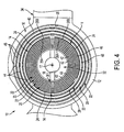
- each conductive member body 24 is preferably either generally circular cylindrical ( Figs. 2 , 3 , 5 and 6 ) or generally arcuate ( Fig. 4 ), but may have any other appropriate shape and/or may include radially or/and axially extending fins or other extensions to increase the heat transfer rate (none depicted).
- each of the one or more bodies 24 is formed of a metallic material, for example aluminum, but may alternatively be fabricated of any other sufficiently thermally conductive material, such as for example, graphene or a composite polymer (e.g., Polyaniline, Polypyrrole, etc.).
- a metallic material for example aluminum
- any other sufficiently thermally conductive material such as for example, graphene or a composite polymer (e.g., Polyaniline, Polypyrrole, etc.).
- each conductive member 14 has an inner axial end 14a attached to the one metallic lamina 22' and an opposing, outer axial end 14b spaced axially from the bearing body 16.
- the conductive member(s) 14 each preferably have an axial length L C between the two ends 14a, 14b that is at least about ten percent (10%) of the axial length L M of the coupled metallic lamina 22', and most preferably between about ten percent (10%) and fifty percent (50%) of the axial length L M .
- each conductive member 14 has a sufficiently large surface area to enable a desired rate of convective heat transfer, as discussed in further detail below
- the inner axial end 14a of the conductive member 14 is attached to the one metallic lamina 22 by any appropriate means, such as for example, a press-fit, threading, welding, brazing, adhesive, rivets, threaded fasteners, etc.
- the one metallic lamina 22' has a generally circular cylindrical shoulder 26 extending axially from the one axial end 22a or 22b and the conductive member 14 has a complementary, generally circular cylindrical shoulder 28 extending axially from the inner axial end 14a.
- the conductive member shoulder 28 is juxtaposeable against the shoulder 26 of the one coupled metallic lamina 22', the conductive member shoulder 28 being disposed either radially inwardly of, or radially outwardly from, the metallic lamina shoulder 26, as best shown in Fig. 8 .
- the complementary shoulders 14 are coupled to connect the conductive member 14 with the one metallic lamina 22, either by complementary threading on the shoulders 14, press-fit established between the shoulders 26, 28 welding or brazing the shoulders 26, 28 together, or attaching the shoulders 26, 28 by rivets, threaded fasteners, or any other appropriate means.
- each conductive member 14 and the coupled metallic lamina 22' may be formed without any shoulders and may instead be joined together by abutting the conductive member inner ends 14a with the metallic lamina ends 12a or 12b, as shown in Fig. 5 , or by radially overlapping the conductive member(s) 14 and the coupled lamina 22' (not shown).
- each conductive member 14 has opposing inner and outer circumferential surfaces 26A, 26B extending at least partially about the body centerline 17.
- Each circumferential surface 26A, 26B is exposed to ambient air (i.e., about the bearing body 16) to enable convective heat transfer from the conductive member 14.
- ambient air i.e., about the bearing body 16
- heat within the coupled metallic lamina 22' flows by conduction into the conductive member 14 and is thereafter transferred from the member 14 by convection.
- the temperature within the one metallic lamina 22', and the two radially-adjacent elastomeric laminae 20 is reduced, which helps prevent thermal degradation of these elastomeric laminae 20.
- the bearing assembly 10 preferably includes at least two conductive members 14 coupled with the metallic lamina 22'. Specifically, at least one first conductive member 15A is coupled with a first axial end 22a of the one metallic lamina 22' and at least one second conductive member 15B is coupled with a second axial end 22b of the metallic lamina 22'.
- first conductive member 15A is coupled with a first axial end 22a of the one metallic lamina 22'
- at least one second conductive member 15B is coupled with a second axial end 22b of the metallic lamina 22'.
- the bearing assembly 10 may have one or more conductive members 14 attached to each one of any desired number of metallic lamina 22, depending on the operating characteristics or environment of the laminated bearing 12.
- the laminated bearing 12 is preferably formed as any one the numerous known conventional laminated elastomeric bearing designs.
- the plurality of elastomeric laminae 20 and metallic laminae 22 of the bearing body 16 are arranged with each metallic lamina 22 being disposed between two radially adjacent elastomeric laminae 20 in a coaxial arrangement, and vice-versa for the majority of the elastomeric lamina 20.
- each one of the elastomeric and metallic laminae 20, 22 has an outside diameter D E , D M , respectively, and the plurality of laminae 20, 22 is arranged such that each one of the laminae 20, 22 is disposed within all of the other laminae 20, 22 having an outside diameter D E , D M greater than the outside diameter D E or D M of the one lamina 20 or 22, as indicated for four randomly selected lamina 20, 22 in Fig. 5 .
- each elastomeric lamina 20 is either formed as a generally continuous, substantially tubular material layer, particularly the inner cylindrical lamina 43 as discussed in detail below, or may be formed as a cylinder cut into one or more sections to facilitate assembly, particularly with the outer partially spherical laminae 44 described below.
- each one of the metallic laminae 22 includes either a continuous, generally circular cylindrical shell 23 (see Fig. 3 ) or a plurality of separate arcuate shells (not shown) spaced circumferentially about the bearing centerline 17.
- the bearing assembly 10 further comprises a generally cylindrical collar 32 disposed within the elastomeric and metallic laminae 20, 22 and a housing 32 configured to at least partially contain the bearing body 16.
- the collar 32 has a central passage providing the bearing bore 18 for receiving the pivotable member 1, preferably the centering pin 2, the innermost elastomeric lamina 21A being bonded to the collar outer surface 32a to connect the collar 32 with the remainder of the bearing body 16.
- the housing 34 has a bore 35, the bearing body 16 being disposed within the housing bore 35 and an outermost elastomeric lamina 21B is preferably bonded with the inner circumferential surface of the housing bore 35.
- the housing 34 is preferably configured to connect the bearing assembly 10 to the rotor assembly 4 and provides a component of the feathering hinge 3.
- the conductive members 14 are utilized with a laminated bearing body 16 that includes a "transition" metallic lamina or "shim" 36 between inner and outer subassemblies 38, 40 of the body 16, the shim 36 thus providing the "one" coupled metallic lamina 22' as described above.
- the plurality of metallic laminae 22 includes an inner set of substantially circular cylindrical laminae 42, an outer set of partially spherical laminae 44 disposed about the inner set of cylindrical metallic laminae 42, and the transition lamina 36, which is disposed between the inner and outer sets of metallic laminae 42, 44 respectively.
- Each elastomeric lamina 20 is bonded, preferably by vulcanization, to at least one radially adjacent metallic lamina 22, i.e., located radially inward and/or radially outward of the lamina 20, such that the elastomeric laminae 20 each take the shape of the adjacent metallic lamina 22.
- an inner set of circular cylindrical elastomeric lamina 43 is bonded to the inner set of metallic laminae 42 to form the bearing inner subassembly 38.
- an outer set of partially spherical elastomeric lamina 45 is bonded to the outer set of metallic laminae 44 to form the bearing outer subassembly 40.
- the transition lamina 36 preferably has a substantially circular-cylindrical inner circumferential surface 37, which correlates with the inner metallic laminae 42, and an at least partially spherical outer circumferential surface 39 that fits in a complementary manner within the outer spherical metallic laminae 44.
- An outermost cylindrical elastomeric lamina 46 of the inner subassembly 38 is bonded to the inner surface 37 of the transition shim 36 and an innermost partially-spherical elastomeric lamina 48 of the outer subassembly 40 is bonded to the outer surface 39 of the transition shim 36, thereby coupling the inner and outer subassemblies 38, 40.
- the bearing body 16 is configured to permit angular displacement of the pivotable member 1 about the bearing centerline 17, primarily by torsional strain of the inner cylindrical elastomeric lamina 43 of the inner subassembly 38.
- the bearing body 16 is also configured to permit angular displacement of the pivotable member 1 about at least one and preferably a plurality of axes 19 (one exemplary axis shown for purposes of illustration only) perpendicular to the bearing centerline 17, due mainly to bending strain of the outer partially spherical elastomeric lamina 45 of the outer subassembly 40.
- the two elastomeric laminae 46, 48 bonded to the transition shim 36 experience relatively greater amounts of strain as compared to the other elastomeric laminae 20, which leads to an increased temperature within the two laminae 46, 48 and the attached transition shim 36.
- the at least one conductive member 14, and preferably at least first and second conductive members 15A, 15B, are each coupled with the ends 22a, 22b of the transition lamina 36 so to provide a means to transfer heat from the transition lamina/shim 36, and thus from the adjacent elastomeric laminae 46, 48.
- the bearing assembly 10 may include additional conductive members 14 coupled with any other metallic lamina 22 in addition to, or instead of, the transition lamina/shim 36.
- any desired number of conductive members 14 may be utilized with any laminated bearing body structure besides the preferred body 12 that includes inner and outer subassemblies 34, 36 and the transition shim 36.
- the bearing body inner and outer subassemblies 38, 40 are separately formed.
- the inner subassembly 38 is installed within the transition shim 36
- the collar 32 is installed within the inner subassembly 38
- the outer subassembly 40 is installed within the housing 34.
- the inner subassembly 38 and the transition shim 36 are then installed within the outer assembly 40, which requires pivoting or cocking of the transition shim 36 to follow the concave curvature of the adjacent outer elastomeric shim 48, as depicted in Fig 10 .
- the conductive members 14 are preferably coupled with the transition shim 36 after installation of the bearing inner subassembly 38 within the outer subassembly 40.
- the conductive member(s) 14 may alternatively be integrally formed with the transition shim 36 (see Fig, 9 ) if another method of assembling the plurality of elastomeric and metallic laminae 20, 22 is utilized.
Landscapes
- Engineering & Computer Science (AREA)
- General Engineering & Computer Science (AREA)
- Mechanical Engineering (AREA)
- Aviation & Aerospace Engineering (AREA)
- Support Of The Bearing (AREA)
- Sliding-Contact Bearings (AREA)
Abstract
Description
- The present invention relates to bearings, and more particularly to laminated elastomeric bearings used in applications such as helicopter rotors.
- Laminated elastomeric bearings are known and include a plurality of alternating, nested elastomeric and metallic layers disposed coaxially about a centerline. Such bearings permit movement of a component, such as a centering pin of a feathering hinge, to pivot or "twist" about the bearing centerline and/or to pivot partially about one or more axes generally perpendicular to the centerline. Such bearings are effective in applications such as the feathering hinge of a rotor assembly, but may experience premature failure due to temperature-induced breakdown of the elastomeric layers in certain sections of the bearing which experience relatively greater amounts of strain.
- In one aspect, the present invention is a bearing assembly for supporting a pivotable member, the bearing assembly comprising a laminated bearing including a generally cylindrical body having a centerline and a central bore for receiving at least a portion of the pivotable member. The body is formed of a plurality of alternating, generally tubular elastomeric and metallic laminae nested coaxially about the central axis, each one of the elastomeric and metallic laminae having opposing axial ends. At least one thermally conductive member is coupled with one of the two axial ends of one of the metallic laminae and extends generally axially from the bearing body so as to provide a heat sink.
- In another aspect, the present invention is again a bearing assembly for supporting a pivotable member. The bearing assembly comprises a laminated bearing including a generally cylindrical body having a central bore and being formed of a plurality of alternating, generally tubular elastomeric and metallic laminae nested coaxially about the central axis, each one of the elastomeric and metallic laminae having opposing axial ends. The plurality of metallic laminae includes an inner set of substantially circular cylindrical laminae, an outer set of partially spherical laminae disposed about the inner set of cylindrical metallic laminae, and a transition metallic lamina disposed between the inner set of laminae and the outer set of laminae. The transition lamina has a substantially circular cylindrical inner circumferential surface and an at least partially spherical outer circumferential surface. Further, at least one thermally conductive member is coupled with one of the two axial ends of the transition lamina and extends generally axially from the bearing body so as to provide a heat sink.
- In a further aspect, the present invention is a feathering hinge for a rotor assembly, the rotor assembly including at least one blade. The hinge assembly comprises a generally cylindrical centering pin coupleable with the at least one rotor blade. A laminated bearing including a generally cylindrical body has a centerline and a central bore for receiving at least a portion of the pin, the body being formed of a plurality of alternating, generally tubular elastomeric and metallic laminae nested coaxially about the central axis, each one of the elastomeric and metallic laminae having opposing axial ends. At least one thermally conductive member is coupled with one of the two axial ends of one of the metallic laminae and extends generally axially from the bearing body so as to provide a heat sink.
- The foregoing summary, as well as the detailed description of the preferred embodiments of the present invention, will be better understood when read in conjunction with the appended drawings. For the purpose of illustrating the invention, there is shown in the drawings, which are diagrammatic, embodiments that are presently preferred. It should be understood, however, that the present invention is not limited to the precise arrangements and instrumentalities shown. In the drawings:
-
Fig. 1 is a partly exploded view of an exemplary rotor assembly, showing a bearing assembly in accordance with the present invention; -
Fig. 2 is a partly broken-away, axial cross-section in perspective of the bearing assembly, showing a centering pin and indicating two pivot axes; -
Fig. 3 is a top plan view of the bearing assembly, showing a continuous cylindrical conductive member; -
Fig. 4 is another top plan view of the bearing assembly, showing a plurality of arcuate conductive members; -
Fig. 5 is an axial cross-sectional view of a laminated elastomeric bearing having two thermally conductive members; -
Fig. 6 is a partly exploded view ofFig. 5 , showing the two conductive members spaced from the bearing body; -
Fig. 7 is an enlarged, broken-away view of a portion ofFig. 5 , showing complementary mating shoulders of a metallic lamina and a conductive member; -
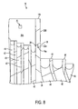
Fig. 8 is a greatly enlarged, broken-away view of a portion ofFig. 5 , showing a sensor mounted to a conductive member; -
Fig. 9 is an axial cross-sectional view of a laminated elastomeric bearing having two conductive members integrally formed with a metallic lamina; and -
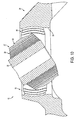
Fig. 10 is an axial cross-sectional view of a laminated elastomeric bearing, depicting a process of installing a bearing inner subassembly within a bearing outer subassembly. - Certain terminology is used in the following description for convenience only and is not limiting. The words "inner", "inwardly" and "outer", "outwardly" refer to directions toward and away from, respectively, a designated centerline or a geometric center of an element being described, the particular meaning being readily apparent from the context of the description. Also, as used herein, the words "connected" or "coupled" are each intended to include integrally formed members, direct connections between two distinct members without any other members interposed therebetween and indirect connections between members in which one or more other members are interposed therebetween. The terminology includes the words specifically mentioned above, derivatives thereof, and words of similar import.
- Referring now to the drawings in detail, wherein like numbers are used to indicate like elements throughout, there is shown in
Figs. 1-10 abearing assembly 10 for supporting apivotable member 1, which is preferably a centeringpin 2 of a feathering hinge 3 incorporated into arotor assembly 4, as shown inFig. 1 . Thebearing assembly 10 basically comprises a laminated elastomeric bearing 12 and at least one thermallyconductive member 14 coupled with thebearing 12. Thebearing 12 includes a generallycylindrical body 16 having acenterline 17 and acentral bore 18 for receiving at least a portion of thepivotable member 1. Thebody 16 is formed of a plurality of alternating, generally tubular elastomeric andmetallic laminae centerline 17. That is, except for an innermost and an outermost elastomeric layer orlamina 20 as discussed below, each tubular or cylindricalelastomeric lamina 20 and each tubular/cylindricalmetallic lamina 22 is disposed or "sandwiched" between two lamina of the other material, i.e., eachmetallic lamina 22 is disposed between twoelastomeric lamina 20, and vice-versa. - Further, each one of the
elastomeric laminae 20 and themetallic laminae 22 has opposingaxial ends metallic laminae 22 having an axial length LM between theends conductive member 14 is coupled with one of the twoaxial ends metallic laminae 22, indicated as lamina 22' hereafter, and extends generally axially (i.e., generally along the centerline 17) from the bearingbody 16 so as to provide a heat sink. Theconductive member 14 is preferably a separate member orbody 24 that is attached to the "coupled" metallic lamina 22' to facilitate assembly, as discussed in further detail below, but may alternatively be an integrally formed extension of the particular lamina 22', as depicted inFig. 9 . More specifically, eachconductive member body 24 is preferably either generally circular cylindrical (Figs. 2 ,3 ,5 and6 ) or generally arcuate (Fig. 4 ), but may have any other appropriate shape and/or may include radially or/and axially extending fins or other extensions to increase the heat transfer rate (none depicted). Preferably, each of the one ormore bodies 24 is formed of a metallic material, for example aluminum, but may alternatively be fabricated of any other sufficiently thermally conductive material, such as for example, graphene or a composite polymer (e.g., Polyaniline, Polypyrrole, etc.). - Furthermore, each
conductive member 14 has an inneraxial end 14a attached to the one metallic lamina 22' and an opposing, outeraxial end 14b spaced axially from the bearingbody 16. As indicated inFig. 6 , the conductive member(s) 14 each preferably have an axial length LC between the twoends conductive member 14 has a sufficiently large surface area to enable a desired rate of convective heat transfer, as discussed in further detail below - Referring to
Figs. 6-8 , the inneraxial end 14a of theconductive member 14 is attached to the onemetallic lamina 22 by any appropriate means, such as for example, a press-fit, threading, welding, brazing, adhesive, rivets, threaded fasteners, etc. Most preferably, the one metallic lamina 22' has a generally circularcylindrical shoulder 26 extending axially from the oneaxial end conductive member 14 has a complementary, generally circularcylindrical shoulder 28 extending axially from the inneraxial end 14a. Theconductive member shoulder 28 is juxtaposeable against theshoulder 26 of the one coupled metallic lamina 22', theconductive member shoulder 28 being disposed either radially inwardly of, or radially outwardly from, themetallic lamina shoulder 26, as best shown inFig. 8 . With this preferred structure, thecomplementary shoulders 14 are coupled to connect theconductive member 14 with the onemetallic lamina 22, either by complementary threading on theshoulders 14, press-fit established between theshoulders shoulders shoulders conductive member 14 and the coupled metallic lamina 22' may be formed without any shoulders and may instead be joined together by abutting the conductive memberinner ends 14a with themetallic lamina ends Fig. 5 , or by radially overlapping the conductive member(s) 14 and the coupled lamina 22' (not shown). - Referring to
Figs. 2-8 , eachconductive member 14 has opposing inner and outercircumferential surfaces body centerline 17. Eachcircumferential surface conductive member 14. As such, heat within the coupled metallic lamina 22' flows by conduction into theconductive member 14 and is thereafter transferred from themember 14 by convection. Thereby, the temperature within the one metallic lamina 22', and the two radially-adjacentelastomeric laminae 20, is reduced, which helps prevent thermal degradation of theseelastomeric laminae 20. - Referring now to
Figs. 2 and5-7 , thebearing assembly 10 preferably includes at least twoconductive members 14 coupled with the metallic lamina 22'. Specifically, at least one firstconductive member 15A is coupled with a firstaxial end 22a of the one metallic lamina 22' and at least one secondconductive member 15B is coupled with a secondaxial end 22b of the metallic lamina 22'. By havingconductive members 14 at eachaxial end elastomeric laminae 20. Further, although depicted as having only first and secondconductive members bearing assembly 10 may have one or moreconductive members 14 attached to each one of any desired number ofmetallic lamina 22, depending on the operating characteristics or environment of the laminatedbearing 12. - Referring particularly to
Fig. 8 , thebearing assembly 10 may further comprise at least onesensor 30 mounted to theconductive member 14. Preferably, thesensor 30 is configured to determine at least temperature of theconductive member 14, thereby providing an indication of the temperature of the coupled metallic lamina 22' and the two adjacentelastomeric laminae 20. However, thesensor 30 may be configured to determine any other physical parameter, such as for example vibration, acceleration, proximity, strain, or environmental characteristics. - Referring now to
Figs. 2-7 , thelaminated bearing 12 is preferably formed as any one the numerous known conventional laminated elastomeric bearing designs. As such, the plurality ofelastomeric laminae 20 andmetallic laminae 22 of the bearingbody 16 are arranged with eachmetallic lamina 22 being disposed between two radially adjacentelastomeric laminae 20 in a coaxial arrangement, and vice-versa for the majority of theelastomeric lamina 20. Also, each one of the elastomeric andmetallic laminae laminae laminae other laminae lamina lamina Fig. 5 . In other words, eachlamina smaller lamina larger lamina - Further, each
elastomeric lamina 20 is either formed as a generally continuous, substantially tubular material layer, particularly the innercylindrical lamina 43 as discussed in detail below, or may be formed as a cylinder cut into one or more sections to facilitate assembly, particularly with the outer partiallyspherical laminae 44 described below. Also, each one of themetallic laminae 22 includes either a continuous, generally circular cylindrical shell 23 (seeFig. 3 ) or a plurality of separate arcuate shells (not shown) spaced circumferentially about the bearingcenterline 17. Preferably, the bearingassembly 10 further comprises a generallycylindrical collar 32 disposed within the elastomeric andmetallic laminae housing 32 configured to at least partially contain the bearingbody 16. Thecollar 32 has a central passage providing the bearing bore 18 for receiving thepivotable member 1, preferably the centeringpin 2, the innermostelastomeric lamina 21A being bonded to the collarouter surface 32a to connect thecollar 32 with the remainder of the bearingbody 16. Furthermore, thehousing 34 has abore 35, the bearingbody 16 being disposed within the housing bore 35 and an outermostelastomeric lamina 21B is preferably bonded with the inner circumferential surface of the housing bore 35. Thehousing 34 is preferably configured to connect the bearingassembly 10 to therotor assembly 4 and provides a component of the feathering hinge 3. - As the laminated bearing structure discussed above is known in the bearing art, a further detailed description of the bearing
body 16 is unnecessary and beyond the scope of the present disclosure, except for the following details of the presently preferred application. Preferably, theconductive members 14 are utilized with alaminated bearing body 16 that includes a "transition" metallic lamina or "shim" 36 between inner andouter subassemblies body 16, theshim 36 thus providing the "one" coupled metallic lamina 22' as described above. Specifically, the plurality ofmetallic laminae 22 includes an inner set of substantially circularcylindrical laminae 42, an outer set of partiallyspherical laminae 44 disposed about the inner set of cylindricalmetallic laminae 42, and thetransition lamina 36, which is disposed between the inner and outer sets ofmetallic laminae - Each
elastomeric lamina 20 is bonded, preferably by vulcanization, to at least one radially adjacentmetallic lamina 22, i.e., located radially inward and/or radially outward of thelamina 20, such that theelastomeric laminae 20 each take the shape of the adjacentmetallic lamina 22. As such, an inner set of circular cylindricalelastomeric lamina 43 is bonded to the inner set ofmetallic laminae 42 to form the bearinginner subassembly 38. Likewise, an outer set of partially sphericalelastomeric lamina 45 is bonded to the outer set ofmetallic laminae 44 to form the bearingouter subassembly 40. Further, thetransition lamina 36 preferably has a substantially circular-cylindrical innercircumferential surface 37, which correlates with the innermetallic laminae 42, and an at least partially spherical outercircumferential surface 39 that fits in a complementary manner within the outer sphericalmetallic laminae 44. An outermost cylindricalelastomeric lamina 46 of theinner subassembly 38 is bonded to theinner surface 37 of thetransition shim 36 and an innermost partially-sphericalelastomeric lamina 48 of theouter subassembly 40 is bonded to theouter surface 39 of thetransition shim 36, thereby coupling the inner andouter subassemblies - With this structure, the bearing
body 16 is configured to permit angular displacement of thepivotable member 1 about the bearingcenterline 17, primarily by torsional strain of the inner cylindricalelastomeric lamina 43 of theinner subassembly 38. The bearingbody 16 is also configured to permit angular displacement of thepivotable member 1 about at least one and preferably a plurality of axes 19 (one exemplary axis shown for purposes of illustration only) perpendicular to the bearingcenterline 17, due mainly to bending strain of the outer partially sphericalelastomeric lamina 45 of theouter subassembly 40. As a result of being located within the transition region between the twosubassemblies elastomeric laminae transition shim 36 experience relatively greater amounts of strain as compared to the otherelastomeric laminae 20, which leads to an increased temperature within the twolaminae transition shim 36. - To reduce this temperature, the at least one
conductive member 14, and preferably at least first and secondconductive members ends transition lamina 36 so to provide a means to transfer heat from the transition lamina/shim 36, and thus from the adjacentelastomeric laminae assembly 10 may include additionalconductive members 14 coupled with any othermetallic lamina 22 in addition to, or instead of, the transition lamina/shim 36. Further, any desired number ofconductive members 14 may be utilized with any laminated bearing body structure besides thepreferred body 12 that includes inner andouter subassemblies transition shim 36. - In a presently favored method of assembling the
preferred bearing body 16, the bearing body inner andouter subassemblies inner subassembly 38 is installed within thetransition shim 36, thecollar 32 is installed within theinner subassembly 38 and theouter subassembly 40 is installed within thehousing 34. Theinner subassembly 38 and thetransition shim 36 are then installed within theouter assembly 40, which requires pivoting or cocking of thetransition shim 36 to follow the concave curvature of the adjacent outerelastomeric shim 48, as depicted inFig 10 . Due to this installation process, theconductive members 14 are preferably coupled with thetransition shim 36 after installation of the bearinginner subassembly 38 within theouter subassembly 40. However, the conductive member(s) 14 may alternatively be integrally formed with the transition shim 36 (seeFig, 9 ) if another method of assembling the plurality of elastomeric andmetallic laminae - It will be appreciated by those skilled in the art that changes could be made to the embodiments described above without departing from the broad inventive concept thereof. It is understood, therefore, that this invention is not limited to the particular embodiments disclosed, but it is intended to cover modifications within the spirit and scope of the present invention as generally defined in the appended claims.
Claims (15)
- A bearing assembly for supporting a pivotable member, the bearing assembly comprising a laminated bearing including a generally cylindrical body having a centerline and a central bore for receiving at least a portion of the pivotable member, the body being formed of a plurality of alternating, generally tubular elastomeric and metallic laminae nested coaxially about the central axis, each one of the elastomeric and metallic laminae having opposing axial ends;
characterized in that the bearing assembly further includes at least one thermally conductive member coupled with one of the two axial ends of one of the metallic laminae and extending generally axially from the bearing body so as to provide a heat sink. - The bearing assembly as recited in claim 1 wherein the at least one conductive member is one of attached to the one metallic lamina and integrally formed with the one metallic lamina.
- The bearing assembly as recited in claim 1 wherein the at least one conductive member includes one of a generally cylindrical body and generally arcuate body and has an inner axial end attached to the one metallic lamina and an opposing, outer axial end spaced axially from the bearing body.
- The bearing assembly as recited in claim 3 wherein the inner axial end of the conductive member is attached to the one metallic lamina by one of a press-fit, threading, welding, brazing, adhesive, rivets and threaded fasteners.
- The bearing assembly as recited in claim 3 wherein the one metallic lamina has a generally cylindrical shoulder extending axially from the one axial end and the conductive member has a generally cylindrical shoulder extending axially from the inner axial end, the conductive member shoulder being juxtaposeable against the shoulder of the one metallic lamina.
- The bearing as recited in claim 1 wherein the at least one conductive member has opposing inner and outer circumferential surfaces, each circumferential surface being exposed to ambient air to enable convective heat transfer from the member.
- The bearing as recited in claim 1 wherein the at least one conductive member is a first conductive member coupled with a first one of the axial ends of the one metallic lamina and the bearing assembly further comprises at least one second conductive member coupled with a second one of the axial ends of the one metallic lamina.
- The bearing assembly as recited in claim 1 further comprising at least one sensor mounted to the conductive member.
- The bearing assembly as recited in claim 6 wherein the sensor is configured to determine at least one of temperature, vibration, acceleration and proximity.
- The bearing assembly as recited in claim 1 wherein each one of the elastomeric and metallic laminae has an outside diameter, the plurality of laminae being arranged such that each one of the laminae is disposed within all of the other laminae having an outside diameter greater than the outside diameter of the one lamina.
- The bearing assembly as recited in claim 1 wherein each one of the metallic laminae includes one of a generally cylindrical shell and a plurality of arcuate shells spaced circumferentially about the axis.
- The bearing assembly as recited in claim 1 wherein the plurality of metallic laminae includes an inner set of substantially circular cylindrical laminae, an outer set of partially spherical laminae disposed about the inner set of cylindrical metallic laminae, and a transition lamina disposed between the inner set of laminae and the outer set of laminae, the transition lamina having a substantially circular cylindrical inner circumferential surface and an at least partly spherical outer circumferential surface, the at least one conductive member being attached to the transition lamina.
- The bearing assembly as recited in claim 1 wherein the bearing body is configured to permit angular displacement of the pivotable member about the bearing centerline and about at least one axis perpendicular to the bearing centerline.
- The bearing assembly as recited in claim 1 further comprising:a generally cylindrical collar disposed within the elastomeric and metallic laminae and having a central passage providing the bearing bore for receiving the pivotable member; anda housing with a bore, the bearing body being disposed within the housing bore.
- The bearing assembly as recited in claim 1 in combination with a feathering hinge for a rotor assembly, the rotor assembly including at least one blade and the hinge including a generally cylindrical centering pin coupleable with the at least one rotor blade, the laminated bearing bore being configured to receive at least a portion of the centering pin.
Applications Claiming Priority (1)
| Application Number | Priority Date | Filing Date | Title |
|---|---|---|---|
| US14/502,037 US10309452B2 (en) | 2014-09-30 | 2014-09-30 | Cylindrical bearing with thermally conductive members |
Publications (3)
| Publication Number | Publication Date |
|---|---|
| EP3015735A2 true EP3015735A2 (en) | 2016-05-04 |
| EP3015735A3 EP3015735A3 (en) | 2016-11-02 |
| EP3015735B1 EP3015735B1 (en) | 2019-12-04 |
Family
ID=54260618
Family Applications (1)
| Application Number | Title | Priority Date | Filing Date |
|---|---|---|---|
| EP15187604.2A Active EP3015735B1 (en) | 2014-09-30 | 2015-09-30 | Cylindrical bearing with thermally conductive members |
Country Status (3)
| Country | Link |
|---|---|
| US (1) | US10309452B2 (en) |
| EP (1) | EP3015735B1 (en) |
| CA (1) | CA2905626C (en) |
Cited By (1)
| Publication number | Priority date | Publication date | Assignee | Title |
|---|---|---|---|---|
| CN110081077A (en) * | 2019-04-09 | 2019-08-02 | 中国航发北京航空材料研究院 | A kind of stable resilient bearing of high radial |
Families Citing this family (12)
| Publication number | Priority date | Publication date | Assignee | Title |
|---|---|---|---|---|
| WO2015066472A1 (en) * | 2013-11-01 | 2015-05-07 | Lord Corporation | Improved riser tensioner bearing system |
| US20160238068A1 (en) * | 2015-02-12 | 2016-08-18 | Aktiebolaget Skf | Combination spherical and laminated bearing |
| US10336446B2 (en) * | 2016-01-04 | 2019-07-02 | Sikorsky Aircraft Corporation | Directional stiffness bearing sleeve assembly for rotor systems |
| US10450060B2 (en) * | 2016-08-05 | 2019-10-22 | Bell Helicopter Textron Inc. | Elastomeric bearing with tab for thermocouple and system for use |
| US10233992B2 (en) * | 2017-07-31 | 2019-03-19 | Aktiebolaget Skf | Elastomeric bearing component with wedge-shaped shims |
| US10627295B2 (en) | 2017-12-19 | 2020-04-21 | David Richard Ungerbuehler | Marine vessel shaft bearing overheat monitor and alarm system |
| US11040771B2 (en) * | 2018-05-08 | 2021-06-22 | Avx Aircraft Company | Rotor hub |
| DE102019200627A1 (en) * | 2019-01-18 | 2020-07-23 | Minebea Mitsumi Inc. | Rolling bearing and pump, in particular turbomolecular pump, with such a rolling bearing |
| US10738852B1 (en) * | 2019-03-29 | 2020-08-11 | Aktiebolaget Skf | Laminated bearing assembly with differing shim thicknesses |
| US11105381B2 (en) * | 2020-02-04 | 2021-08-31 | Aktiebolaget Skf | Rotor assembly bearing with centrifugal clutch mechanism |
| CN112178052A (en) * | 2020-10-13 | 2021-01-05 | 株洲时代新材料科技股份有限公司 | Laminated rubber and metal elastic bearing |
| US11732747B2 (en) * | 2022-01-05 | 2023-08-22 | Textron Innovations Inc. | Journal bearings |
Family Cites Families (42)
| Publication number | Priority date | Publication date | Assignee | Title |
|---|---|---|---|---|
| GB352898A (en) * | 1930-03-05 | 1931-07-16 | Nomy Ab | Improvements in or relating to bearings |
| FR1429483A (en) * | 1964-02-24 | 1966-02-25 | Composite body intended for the manufacture of bearing elements | |
| US4040690A (en) * | 1975-11-17 | 1977-08-09 | Lord Corporation | Laminated bearing |
| US4123122A (en) * | 1976-07-06 | 1978-10-31 | The Torrington Company | Bearing element |
| US4435097A (en) * | 1977-06-15 | 1984-03-06 | Barry Wright Corporation | Laminated bearing structures |
| US4256354A (en) * | 1979-03-05 | 1981-03-17 | Barry Wright Corporation | Laminated bearing structures |
| US4286827A (en) * | 1979-10-11 | 1981-09-01 | Barry Wright Corporation | Cylindrical elastomeric bearing |
| US4358167A (en) * | 1981-05-26 | 1982-11-09 | The Torrington Company | Bearing element |
| US4357057A (en) * | 1981-07-27 | 1982-11-02 | Barry Wright Corporation | Laminated bearing with improved low temperature operating characteristics |
| US4895354A (en) * | 1985-05-13 | 1990-01-23 | United Technologies Corporation | Equalizing stress distribution in each laminate of an asymmetrically loaded elastomeric bearing |
| US4729753A (en) * | 1985-11-04 | 1988-03-08 | Bell Helicopter Textron Inc. | Constant velocity elastomeric bearing joint |
| US4804352A (en) * | 1987-01-30 | 1989-02-14 | Lord Corporation | Link-type rotary coupling |
| US4886419A (en) * | 1988-09-30 | 1989-12-12 | The Boeing Company | Elastomeric bearing for helicopter rotor having lead-lag damping |
| US4986735A (en) * | 1989-10-13 | 1991-01-22 | Bell Helicopter Textron, Inc. | Pitch change bearing system |
| US5092738A (en) * | 1990-04-06 | 1992-03-03 | United Technologies Corporation | Flexbeam helicopter rotor with improved snubber-vibration damper between the torque tube and the flexible spar member |
| US5186686A (en) * | 1990-05-11 | 1993-02-16 | Lord Corporation | Link and bearing for rotary coupling |
| US5188513A (en) * | 1990-12-17 | 1993-02-23 | United Technologies Corporation | Snubber-bearing with combined elastomer laminates |
| BE1006178A4 (en) * | 1992-09-14 | 1994-05-31 | Previnaire Emmanuel Etienne | Device for detection device, especially for appliance of shooting. |
| DE69317060T2 (en) * | 1992-12-23 | 1998-09-10 | United Technologies Corp | TUBULAR ELASTOM DAMPER |
| US5913659A (en) * | 1993-11-22 | 1999-06-22 | United Technologies Corporation | Apparatus and method for adjusting rotor blade tracking |
| JP3526117B2 (en) * | 1994-11-07 | 2004-05-10 | 株式会社小松製作所 | Liquid filled suspension |
| US5601408A (en) * | 1996-03-18 | 1997-02-11 | Sikorsky Aircraft Corporation | Axisymmetric elastomeric bearing assembly for helicopter rotors |
| US6189874B1 (en) * | 1997-07-01 | 2001-02-20 | Lord Corporation | X-configuration engine mounting |
| FR2778165B1 (en) * | 1998-04-29 | 2000-07-13 | Eurocopter France | NON-ARTICULATING ROTOR WITH PRE-COMPRESSED HALF BEARINGS SUPPORTING BLADE FOOT SLEEVES ON TORSIBLE BLADES FOR BLADES |
| US6045328A (en) * | 1998-09-23 | 2000-04-04 | Lord Corporation | Fluid damper including flexible damping plate |
| US6325687B1 (en) * | 2000-08-14 | 2001-12-04 | David Ungerbuehler | Overheat indicator for strut bearing and stern tube bearing |
| US6695583B2 (en) * | 2002-05-30 | 2004-02-24 | Sikorsky Aircraft Corporation | Snubber-vibration damper system for a bearingless main rotor |
| US7201367B2 (en) * | 2002-12-12 | 2007-04-10 | Caterpillar Inc | Load-bearing resilient mount |
| US7097169B2 (en) * | 2004-08-04 | 2006-08-29 | Skf Usa Inc. | Elastomeric bearing with modified cylindrical core |
| US7354248B2 (en) * | 2005-10-17 | 2008-04-08 | Sikorsky Aircraft Corporation | Elastomeric bearing elements for droop stop mechanisms |
| WO2008091376A2 (en) * | 2006-07-25 | 2008-07-31 | Lord Corporation | Tiltrotor aircraft drivelink |
| US8152146B2 (en) * | 2008-03-10 | 2012-04-10 | The Pullman Company | External shear-hub isolator |
| CN101534624B (en) * | 2008-03-14 | 2012-10-10 | 富准精密工业(深圳)有限公司 | Radiator combination |
| WO2010072232A1 (en) * | 2008-12-22 | 2010-07-01 | Ab Skf | Sensorized bearing unit |
| US8632062B2 (en) * | 2009-11-23 | 2014-01-21 | Lord Corporation | Elastomeric high capacity laminated rotary wing aircraft bearing for rotary wing aircraft |
| CA2828087C (en) * | 2011-02-24 | 2016-08-09 | Bell Helicopter Textron Inc. | A temperature adaptive fluid damping system |
| US9260185B2 (en) * | 2012-01-25 | 2016-02-16 | Textron Innovations Inc. | System and method of harvesting power with a rotor hub damper |
| FR2993244B1 (en) * | 2012-07-12 | 2014-07-18 | Eurocopter France | ROTOR OF GIRAVION EQUIPPED WITH TRAINEE SHOCK ABSORBERS IN BLADE CONNECTION SLEEVES WITH ROTOR HUB |
| CN102829114A (en) * | 2012-08-28 | 2012-12-19 | 中国航空工业集团公司北京航空材料研究院 | Auxiliary rubber spring for automobile suspension |
| US9458877B2 (en) * | 2013-01-24 | 2016-10-04 | The Boeing Company | Multi-directional elastomeric dampened ball joint assembly |
| US9383267B2 (en) * | 2013-05-31 | 2016-07-05 | Purdue Research Foundation | Wireless sensor for rotating elements |
| US20150225076A1 (en) * | 2013-06-03 | 2015-08-13 | Proenterpriz, Inc. | Pressure jet propulsion system |
-
2014
- 2014-09-30 US US14/502,037 patent/US10309452B2/en active Active
-
2015
- 2015-09-23 CA CA2905626A patent/CA2905626C/en active Active
- 2015-09-30 EP EP15187604.2A patent/EP3015735B1/en active Active
Non-Patent Citations (1)
| Title |
|---|
| None |
Cited By (1)
| Publication number | Priority date | Publication date | Assignee | Title |
|---|---|---|---|---|
| CN110081077A (en) * | 2019-04-09 | 2019-08-02 | 中国航发北京航空材料研究院 | A kind of stable resilient bearing of high radial |
Also Published As
| Publication number | Publication date |
|---|---|
| EP3015735B1 (en) | 2019-12-04 |
| EP3015735A3 (en) | 2016-11-02 |
| CA2905626C (en) | 2023-01-17 |
| US20160091017A1 (en) | 2016-03-31 |
| US10309452B2 (en) | 2019-06-04 |
| CA2905626A1 (en) | 2016-03-30 |
Similar Documents
| Publication | Publication Date | Title |
|---|---|---|
| EP3015735B1 (en) | Cylindrical bearing with thermally conductive members | |
| CN106151263B (en) | Combined spherical laminated bearing assemblies | |
| CN110030260B (en) | Combined elastomer and cylindrical plain bearings | |
| US5186686A (en) | Link and bearing for rotary coupling | |
| US10214284B2 (en) | Pitch bearing | |
| US20020154940A1 (en) | Device for damped elastic connection and method of manufacturing it | |
| EP3486511B1 (en) | Combination elastomeric and ellipsoidal plain bearing | |
| JP2017524884A (en) | Rotating link assembly | |
| EP2959179A1 (en) | Partitioned elastomeric journal bearing assemblies, systems and methods | |
| JPS6160397A (en) | Flexible swash plate centering member | |
| US10738852B1 (en) | Laminated bearing assembly with differing shim thicknesses | |
| US10408544B2 (en) | Composite top case with embedded heat pipes | |
| US7686584B2 (en) | Elastomeric bearing with heatable shims | |
| US9802698B2 (en) | Rotor hub for rotary wing aircraft | |
| EP2799730B1 (en) | Hybrid sliding element and elastomeric bearing | |
| CN110206646B (en) | Aeroengine bearing support subassembly and aeroengine | |
| US8591136B2 (en) | Non-rotating universal joint for a helicopter drive unit | |
| JP2016161270A (en) | Radome ring for flying objects | |
| EP3536998B1 (en) | Self-centering flexible coupling | |
| US11105381B2 (en) | Rotor assembly bearing with centrifugal clutch mechanism | |
| CN207333472U (en) | A kind of monoblock type shaft coupling | |
| JP2019536956A (en) | Torsion bar spring | |
| CN107575495A (en) | A kind of monoblock type shaft coupling | |
| US20180163777A1 (en) | Bearing Liner for Accommodating Thermal Expansion and Transmission System Incorporating the Same | |
| JP7154182B2 (en) | flying body |
Legal Events
| Date | Code | Title | Description |
|---|---|---|---|
| PUAI | Public reference made under article 153(3) epc to a published international application that has entered the european phase |
Free format text: ORIGINAL CODE: 0009012 |
|
| AK | Designated contracting states |
Kind code of ref document: A2 Designated state(s): AL AT BE BG CH CY CZ DE DK EE ES FI FR GB GR HR HU IE IS IT LI LT LU LV MC MK MT NL NO PL PT RO RS SE SI SK SM TR |
|
| AX | Request for extension of the european patent |
Extension state: BA ME |
|
| PUAL | Search report despatched |
Free format text: ORIGINAL CODE: 0009013 |
|
| AK | Designated contracting states |
Kind code of ref document: A3 Designated state(s): AL AT BE BG CH CY CZ DE DK EE ES FI FR GB GR HR HU IE IS IT LI LT LU LV MC MK MT NL NO PL PT RO RS SE SI SK SM TR |
|
| AX | Request for extension of the european patent |
Extension state: BA ME |
|
| RIC1 | Information provided on ipc code assigned before grant |
Ipc: F16C 27/06 20060101ALI20160929BHEP Ipc: B64C 27/32 20060101ALI20160929BHEP Ipc: F16C 17/22 20060101ALI20160929BHEP Ipc: F16F 1/387 20060101AFI20160929BHEP Ipc: F16F 1/393 20060101ALI20160929BHEP |
|
| 17P | Request for examination filed |
Effective date: 20170427 |
|
| RBV | Designated contracting states (corrected) |
Designated state(s): AL AT BE BG CH CY CZ DE DK EE ES FI FR GB GR HR HU IE IS IT LI LT LU LV MC MK MT NL NO PL PT RO RS SE SI SK SM TR |
|
| STAA | Information on the status of an ep patent application or granted ep patent |
Free format text: STATUS: REQUEST FOR EXAMINATION WAS MADE |
|
| STAA | Information on the status of an ep patent application or granted ep patent |
Free format text: STATUS: EXAMINATION IS IN PROGRESS |
|
| 17Q | First examination report despatched |
Effective date: 20170905 |
|
| GRAP | Despatch of communication of intention to grant a patent |
Free format text: ORIGINAL CODE: EPIDOSNIGR1 |
|
| STAA | Information on the status of an ep patent application or granted ep patent |
Free format text: STATUS: GRANT OF PATENT IS INTENDED |
|
| INTG | Intention to grant announced |
Effective date: 20190627 |
|
| GRAS | Grant fee paid |
Free format text: ORIGINAL CODE: EPIDOSNIGR3 |
|
| GRAA | (expected) grant |
Free format text: ORIGINAL CODE: 0009210 |
|
| STAA | Information on the status of an ep patent application or granted ep patent |
Free format text: STATUS: THE PATENT HAS BEEN GRANTED |
|
| AK | Designated contracting states |
Kind code of ref document: B1 Designated state(s): AL AT BE BG CH CY CZ DE DK EE ES FI FR GB GR HR HU IE IS IT LI LT LU LV MC MK MT NL NO PL PT RO RS SE SI SK SM TR |
|
| REG | Reference to a national code |
Ref country code: GB Ref legal event code: FG4D |
|
| REG | Reference to a national code |
Ref country code: CH Ref legal event code: EP |
|
| REG | Reference to a national code |
Ref country code: AT Ref legal event code: REF Ref document number: 1209803 Country of ref document: AT Kind code of ref document: T Effective date: 20191215 |
|
| REG | Reference to a national code |
Ref country code: DE Ref legal event code: R096 Ref document number: 602015042843 Country of ref document: DE |
|
| REG | Reference to a national code |
Ref country code: IE Ref legal event code: FG4D |
|
| REG | Reference to a national code |
Ref country code: NL Ref legal event code: MP Effective date: 20191204 |
|
| REG | Reference to a national code |
Ref country code: LT Ref legal event code: MG4D |
|
| PG25 | Lapsed in a contracting state [announced via postgrant information from national office to epo] |
Ref country code: LV Free format text: LAPSE BECAUSE OF FAILURE TO SUBMIT A TRANSLATION OF THE DESCRIPTION OR TO PAY THE FEE WITHIN THE PRESCRIBED TIME-LIMIT Effective date: 20191204 Ref country code: LT Free format text: LAPSE BECAUSE OF FAILURE TO SUBMIT A TRANSLATION OF THE DESCRIPTION OR TO PAY THE FEE WITHIN THE PRESCRIBED TIME-LIMIT Effective date: 20191204 Ref country code: NO Free format text: LAPSE BECAUSE OF FAILURE TO SUBMIT A TRANSLATION OF THE DESCRIPTION OR TO PAY THE FEE WITHIN THE PRESCRIBED TIME-LIMIT Effective date: 20200304 Ref country code: GR Free format text: LAPSE BECAUSE OF FAILURE TO SUBMIT A TRANSLATION OF THE DESCRIPTION OR TO PAY THE FEE WITHIN THE PRESCRIBED TIME-LIMIT Effective date: 20200305 Ref country code: BG Free format text: LAPSE BECAUSE OF FAILURE TO SUBMIT A TRANSLATION OF THE DESCRIPTION OR TO PAY THE FEE WITHIN THE PRESCRIBED TIME-LIMIT Effective date: 20200304 Ref country code: SE Free format text: LAPSE BECAUSE OF FAILURE TO SUBMIT A TRANSLATION OF THE DESCRIPTION OR TO PAY THE FEE WITHIN THE PRESCRIBED TIME-LIMIT Effective date: 20191204 Ref country code: FI Free format text: LAPSE BECAUSE OF FAILURE TO SUBMIT A TRANSLATION OF THE DESCRIPTION OR TO PAY THE FEE WITHIN THE PRESCRIBED TIME-LIMIT Effective date: 20191204 |
|
| PG25 | Lapsed in a contracting state [announced via postgrant information from national office to epo] |
Ref country code: RS Free format text: LAPSE BECAUSE OF FAILURE TO SUBMIT A TRANSLATION OF THE DESCRIPTION OR TO PAY THE FEE WITHIN THE PRESCRIBED TIME-LIMIT Effective date: 20191204 Ref country code: HR Free format text: LAPSE BECAUSE OF FAILURE TO SUBMIT A TRANSLATION OF THE DESCRIPTION OR TO PAY THE FEE WITHIN THE PRESCRIBED TIME-LIMIT Effective date: 20191204 |
|
| PG25 | Lapsed in a contracting state [announced via postgrant information from national office to epo] |
Ref country code: AL Free format text: LAPSE BECAUSE OF FAILURE TO SUBMIT A TRANSLATION OF THE DESCRIPTION OR TO PAY THE FEE WITHIN THE PRESCRIBED TIME-LIMIT Effective date: 20191204 |
|
| PG25 | Lapsed in a contracting state [announced via postgrant information from national office to epo] |
Ref country code: EE Free format text: LAPSE BECAUSE OF FAILURE TO SUBMIT A TRANSLATION OF THE DESCRIPTION OR TO PAY THE FEE WITHIN THE PRESCRIBED TIME-LIMIT Effective date: 20191204 Ref country code: ES Free format text: LAPSE BECAUSE OF FAILURE TO SUBMIT A TRANSLATION OF THE DESCRIPTION OR TO PAY THE FEE WITHIN THE PRESCRIBED TIME-LIMIT Effective date: 20191204 Ref country code: PT Free format text: LAPSE BECAUSE OF FAILURE TO SUBMIT A TRANSLATION OF THE DESCRIPTION OR TO PAY THE FEE WITHIN THE PRESCRIBED TIME-LIMIT Effective date: 20200429 Ref country code: CZ Free format text: LAPSE BECAUSE OF FAILURE TO SUBMIT A TRANSLATION OF THE DESCRIPTION OR TO PAY THE FEE WITHIN THE PRESCRIBED TIME-LIMIT Effective date: 20191204 Ref country code: NL Free format text: LAPSE BECAUSE OF FAILURE TO SUBMIT A TRANSLATION OF THE DESCRIPTION OR TO PAY THE FEE WITHIN THE PRESCRIBED TIME-LIMIT Effective date: 20191204 Ref country code: RO Free format text: LAPSE BECAUSE OF FAILURE TO SUBMIT A TRANSLATION OF THE DESCRIPTION OR TO PAY THE FEE WITHIN THE PRESCRIBED TIME-LIMIT Effective date: 20191204 |
|
| PG25 | Lapsed in a contracting state [announced via postgrant information from national office to epo] |
Ref country code: SM Free format text: LAPSE BECAUSE OF FAILURE TO SUBMIT A TRANSLATION OF THE DESCRIPTION OR TO PAY THE FEE WITHIN THE PRESCRIBED TIME-LIMIT Effective date: 20191204 Ref country code: IS Free format text: LAPSE BECAUSE OF FAILURE TO SUBMIT A TRANSLATION OF THE DESCRIPTION OR TO PAY THE FEE WITHIN THE PRESCRIBED TIME-LIMIT Effective date: 20200404 Ref country code: SK Free format text: LAPSE BECAUSE OF FAILURE TO SUBMIT A TRANSLATION OF THE DESCRIPTION OR TO PAY THE FEE WITHIN THE PRESCRIBED TIME-LIMIT Effective date: 20191204 |
|
| REG | Reference to a national code |
Ref country code: DE Ref legal event code: R097 Ref document number: 602015042843 Country of ref document: DE |
|
| REG | Reference to a national code |
Ref country code: AT Ref legal event code: MK05 Ref document number: 1209803 Country of ref document: AT Kind code of ref document: T Effective date: 20191204 |
|
| PLBE | No opposition filed within time limit |
Free format text: ORIGINAL CODE: 0009261 |
|
| STAA | Information on the status of an ep patent application or granted ep patent |
Free format text: STATUS: NO OPPOSITION FILED WITHIN TIME LIMIT |
|
| PG25 | Lapsed in a contracting state [announced via postgrant information from national office to epo] |
Ref country code: DK Free format text: LAPSE BECAUSE OF FAILURE TO SUBMIT A TRANSLATION OF THE DESCRIPTION OR TO PAY THE FEE WITHIN THE PRESCRIBED TIME-LIMIT Effective date: 20191204 |
|
| 26N | No opposition filed |
Effective date: 20200907 |
|
| PG25 | Lapsed in a contracting state [announced via postgrant information from national office to epo] |
Ref country code: SI Free format text: LAPSE BECAUSE OF FAILURE TO SUBMIT A TRANSLATION OF THE DESCRIPTION OR TO PAY THE FEE WITHIN THE PRESCRIBED TIME-LIMIT Effective date: 20191204 Ref country code: AT Free format text: LAPSE BECAUSE OF FAILURE TO SUBMIT A TRANSLATION OF THE DESCRIPTION OR TO PAY THE FEE WITHIN THE PRESCRIBED TIME-LIMIT Effective date: 20191204 Ref country code: PL Free format text: LAPSE BECAUSE OF FAILURE TO SUBMIT A TRANSLATION OF THE DESCRIPTION OR TO PAY THE FEE WITHIN THE PRESCRIBED TIME-LIMIT Effective date: 20191204 |
|
| PG25 | Lapsed in a contracting state [announced via postgrant information from national office to epo] |
Ref country code: IT Free format text: LAPSE BECAUSE OF FAILURE TO SUBMIT A TRANSLATION OF THE DESCRIPTION OR TO PAY THE FEE WITHIN THE PRESCRIBED TIME-LIMIT Effective date: 20191204 |
|
| PG25 | Lapsed in a contracting state [announced via postgrant information from national office to epo] |
Ref country code: MC Free format text: LAPSE BECAUSE OF FAILURE TO SUBMIT A TRANSLATION OF THE DESCRIPTION OR TO PAY THE FEE WITHIN THE PRESCRIBED TIME-LIMIT Effective date: 20191204 |
|
| REG | Reference to a national code |
Ref country code: CH Ref legal event code: PL |
|
| REG | Reference to a national code |
Ref country code: BE Ref legal event code: MM Effective date: 20200930 |
|
| PG25 | Lapsed in a contracting state [announced via postgrant information from national office to epo] |
Ref country code: LU Free format text: LAPSE BECAUSE OF NON-PAYMENT OF DUE FEES Effective date: 20200930 |
|
| PG25 | Lapsed in a contracting state [announced via postgrant information from national office to epo] |
Ref country code: LI Free format text: LAPSE BECAUSE OF NON-PAYMENT OF DUE FEES Effective date: 20200930 Ref country code: IE Free format text: LAPSE BECAUSE OF NON-PAYMENT OF DUE FEES Effective date: 20200930 Ref country code: CH Free format text: LAPSE BECAUSE OF NON-PAYMENT OF DUE FEES Effective date: 20200930 Ref country code: BE Free format text: LAPSE BECAUSE OF NON-PAYMENT OF DUE FEES Effective date: 20200930 |
|
| PG25 | Lapsed in a contracting state [announced via postgrant information from national office to epo] |
Ref country code: TR Free format text: LAPSE BECAUSE OF FAILURE TO SUBMIT A TRANSLATION OF THE DESCRIPTION OR TO PAY THE FEE WITHIN THE PRESCRIBED TIME-LIMIT Effective date: 20191204 Ref country code: MT Free format text: LAPSE BECAUSE OF FAILURE TO SUBMIT A TRANSLATION OF THE DESCRIPTION OR TO PAY THE FEE WITHIN THE PRESCRIBED TIME-LIMIT Effective date: 20191204 Ref country code: CY Free format text: LAPSE BECAUSE OF FAILURE TO SUBMIT A TRANSLATION OF THE DESCRIPTION OR TO PAY THE FEE WITHIN THE PRESCRIBED TIME-LIMIT Effective date: 20191204 |
|
| PG25 | Lapsed in a contracting state [announced via postgrant information from national office to epo] |
Ref country code: MK Free format text: LAPSE BECAUSE OF FAILURE TO SUBMIT A TRANSLATION OF THE DESCRIPTION OR TO PAY THE FEE WITHIN THE PRESCRIBED TIME-LIMIT Effective date: 20191204 |
|
| P01 | Opt-out of the competence of the unified patent court (upc) registered |
Effective date: 20230513 |
|
| PGFP | Annual fee paid to national office [announced via postgrant information from national office to epo] |
Ref country code: DE Payment date: 20250926 Year of fee payment: 11 |
|
| PGFP | Annual fee paid to national office [announced via postgrant information from national office to epo] |
Ref country code: GB Payment date: 20250923 Year of fee payment: 11 |
|
| PGFP | Annual fee paid to national office [announced via postgrant information from national office to epo] |
Ref country code: FR Payment date: 20250925 Year of fee payment: 11 |