EP3015713A1 - Blower apparatus - Google Patents
Blower apparatus Download PDFInfo
- Publication number
- EP3015713A1 EP3015713A1 EP15173114.8A EP15173114A EP3015713A1 EP 3015713 A1 EP3015713 A1 EP 3015713A1 EP 15173114 A EP15173114 A EP 15173114A EP 3015713 A1 EP3015713 A1 EP 3015713A1
- Authority
- EP
- European Patent Office
- Prior art keywords
- curved
- impeller
- rotation direction
- respect
- cover
- Prior art date
- Legal status (The legal status is an assumption and is not a legal conclusion. Google has not performed a legal analysis and makes no representation as to the accuracy of the status listed.)
- Withdrawn
Links
- 238000011144 upstream manufacturing Methods 0.000 claims description 16
- 230000003247 decreasing effect Effects 0.000 claims description 5
- 230000007423 decrease Effects 0.000 claims description 2
- 230000000694 effects Effects 0.000 description 3
- 238000012986 modification Methods 0.000 description 3
- 230000004048 modification Effects 0.000 description 3
- 238000000926 separation method Methods 0.000 description 3
- 230000003068 static effect Effects 0.000 description 3
- 238000010586 diagram Methods 0.000 description 1
- 239000002184 metal Substances 0.000 description 1
- 238000000465 moulding Methods 0.000 description 1
- 239000011347 resin Substances 0.000 description 1
- 229920005989 resin Polymers 0.000 description 1
Images



Classifications
-
- F—MECHANICAL ENGINEERING; LIGHTING; HEATING; WEAPONS; BLASTING
- F04—POSITIVE - DISPLACEMENT MACHINES FOR LIQUIDS; PUMPS FOR LIQUIDS OR ELASTIC FLUIDS
- F04D—NON-POSITIVE-DISPLACEMENT PUMPS
- F04D29/00—Details, component parts, or accessories
- F04D29/40—Casings; Connections of working fluid
- F04D29/42—Casings; Connections of working fluid for radial or helico-centrifugal pumps
- F04D29/44—Fluid-guiding means, e.g. diffusers
- F04D29/441—Fluid-guiding means, e.g. diffusers especially adapted for elastic fluid pumps
- F04D29/444—Bladed diffusers
-
- A—HUMAN NECESSITIES
- A47—FURNITURE; DOMESTIC ARTICLES OR APPLIANCES; COFFEE MILLS; SPICE MILLS; SUCTION CLEANERS IN GENERAL
- A47L—DOMESTIC WASHING OR CLEANING; SUCTION CLEANERS IN GENERAL
- A47L5/00—Structural features of suction cleaners
- A47L5/12—Structural features of suction cleaners with power-driven air-pumps or air-compressors, e.g. driven by motor vehicle engine vacuum
- A47L5/22—Structural features of suction cleaners with power-driven air-pumps or air-compressors, e.g. driven by motor vehicle engine vacuum with rotary fans
- A47L5/28—Suction cleaners with handles and nozzles fixed on the casings, e.g. wheeled suction cleaners with steering handle
-
- F—MECHANICAL ENGINEERING; LIGHTING; HEATING; WEAPONS; BLASTING
- F04—POSITIVE - DISPLACEMENT MACHINES FOR LIQUIDS; PUMPS FOR LIQUIDS OR ELASTIC FLUIDS
- F04D—NON-POSITIVE-DISPLACEMENT PUMPS
- F04D17/00—Radial-flow pumps, e.g. centrifugal pumps; Helico-centrifugal pumps
- F04D17/08—Centrifugal pumps
- F04D17/16—Centrifugal pumps for displacing without appreciable compression
-
- F—MECHANICAL ENGINEERING; LIGHTING; HEATING; WEAPONS; BLASTING
- F04—POSITIVE - DISPLACEMENT MACHINES FOR LIQUIDS; PUMPS FOR LIQUIDS OR ELASTIC FLUIDS
- F04D—NON-POSITIVE-DISPLACEMENT PUMPS
- F04D25/00—Pumping installations or systems
- F04D25/02—Units comprising pumps and their driving means
- F04D25/06—Units comprising pumps and their driving means the pump being electrically driven
-
- F—MECHANICAL ENGINEERING; LIGHTING; HEATING; WEAPONS; BLASTING
- F04—POSITIVE - DISPLACEMENT MACHINES FOR LIQUIDS; PUMPS FOR LIQUIDS OR ELASTIC FLUIDS
- F04D—NON-POSITIVE-DISPLACEMENT PUMPS
- F04D29/00—Details, component parts, or accessories
- F04D29/26—Rotors specially for elastic fluids
- F04D29/28—Rotors specially for elastic fluids for centrifugal or helico-centrifugal pumps for radial-flow or helico-centrifugal pumps
- F04D29/281—Rotors specially for elastic fluids for centrifugal or helico-centrifugal pumps for radial-flow or helico-centrifugal pumps for fans or blowers
-
- F—MECHANICAL ENGINEERING; LIGHTING; HEATING; WEAPONS; BLASTING
- F04—POSITIVE - DISPLACEMENT MACHINES FOR LIQUIDS; PUMPS FOR LIQUIDS OR ELASTIC FLUIDS
- F04D—NON-POSITIVE-DISPLACEMENT PUMPS
- F04D29/00—Details, component parts, or accessories
- F04D29/40—Casings; Connections of working fluid
- F04D29/42—Casings; Connections of working fluid for radial or helico-centrifugal pumps
- F04D29/44—Fluid-guiding means, e.g. diffusers
- F04D29/441—Fluid-guiding means, e.g. diffusers especially adapted for elastic fluid pumps
-
- F—MECHANICAL ENGINEERING; LIGHTING; HEATING; WEAPONS; BLASTING
- F05—INDEXING SCHEMES RELATING TO ENGINES OR PUMPS IN VARIOUS SUBCLASSES OF CLASSES F01-F04
- F05D—INDEXING SCHEME FOR ASPECTS RELATING TO NON-POSITIVE-DISPLACEMENT MACHINES OR ENGINES, GAS-TURBINES OR JET-PROPULSION PLANTS
- F05D2250/00—Geometry
- F05D2250/50—Inlet or outlet
- F05D2250/52—Outlet
Definitions
- the present invention relates to an electric blower apparatus.
- the blower apparatus is installed in, for example, a vacuum cleaner.
- Blower apparatuses installed in vacuum cleaners are required to have a high static pressure.
- blower apparatuses are disclosed in, for example, JP-A 2010-281232 and JP-A 2011-80427 .
- plate-shaped air guides are provided to guide a flow of air downward from a lateral side of an impeller. The air is sucked in through a center of the impeller, and is sent radially outward from the impeller. The air is then guided to a space radially outside of a motor arranged below through the air guides.
- Each of the plate-shaped air guides which are arranged to downwardly guide air sent radially outward from the impeller, includes a curved portion which is inclined to guide the flow of air, but when the impeller rotates at a high speed, a separation of the air may occur at a surface of any air guide to cause noise.
- a reduction in noise is particularly important when the blower apparatus is used in a consumer product, such as, for example, a vacuum cleaner.
- a blower apparatus includes a motor portion having a central axis extending in a vertical direction, an impeller, an impeller cover portion, a body cover portion, and a plurality of guide vanes.
- the impeller is arranged above the motor portion, is joined to a rotating portion of the motor portion, and is arranged to rotate to suck a gas from above and send the gas radially outward.
- the impeller cover portion includes an inner circumferential surface arranged to cover an outer circumference of the impeller and an upper side of an outer edge portion of the impeller, and further includes an air inlet defined in a center thereof.
- the body cover portion is joined to the impeller cover portion, is arranged to cover an outer circumference of the motor portion, and is arranged to define a tubular space between the motor portion and the body cover portion.
- the plurality of guide vanes are arranged at regular intervals in a circumferential direction in the tubular space, and are arranged to define an air channel which guides the gas sent from the impeller downward.
- Each guide vane is arranged to extend in a radial direction between an inner circumferential surface of the body cover portion and an outer circumferential surface of the motor portion.
- Each of the plurality of guide vanes includes a curved portion arranged at an upper portion thereof, and a straight portion continuous with the curved portion and arranged to extend downward therefrom.
- the curved portion is curved in a direction opposite to a rotation direction of the impeller with increasing height.
- a downstream surface of the curved portion with respect to the rotation direction includes at least two curved surfaces continuous with each other.
- An upper one of the at least two curved surfaces of the curved portion has a radius of curvature greater than a radius of curvature of a lower one of the at least two curved surfaces.
- the above preferred embodiment of the present invention is able to reduce noise of the blower apparatus while maintaining a high static pressure of the blower apparatus.
- blower apparatus according to a preferred embodiment of the present invention will be described with reference to the accompanying drawings. It is assumed herein that a direction parallel or substantially parallel to a central axis of a blower apparatus is referred to by the term “axial direction”, “axial”, or “axially”, that directions perpendicular or substantially perpendicular to the central axis of the blower apparatus are each referred to by the term “radial direction”, “radial”, or “radially”, and that a direction along a circular arc centered on the central axis of the blower apparatus is referred to by the term “circumferential direction”, “circumferential”, or “circumferentially”.
- an axial direction is a vertical direction
- a side on which an impeller is arranged with respect to a motor portion is defined as an upper side.
- the shape of each member or portion and relative positions of different members or portions will be described based on the above assumptions. It should be noted, however, that the above definitions of the vertical direction and the upper side are not meant to restrict in any way the orientation of a blower apparatus according to any preferred embodiment of the present invention when in use.
- FIG. 1 is a perspective view illustrating an overall structure of a blower apparatus 1 according to a preferred embodiment of the present invention.
- the blower apparatus 1 includes a motor portion 50, an impeller 40, an impeller cover portion 14, a body cover portion, and a plurality of guide vanes 70.
- the blower apparatus 1 includes an upper cover 10 and a lower cover 20 arranged at an outer portion thereof.
- the upper cover 10 includes the impeller cover portion 14 and a cover body portion 18.
- the impeller cover portion 14 is made of a metal, is in the shape of a cap, and includes an air inlet 12 defined in a central portion of an upper surface thereof.
- the cover body portion 18 includes a cylindrical portion to which a cylindrical portion of the impeller cover portion 14 is fitted from radially outside, and an upper flange portion 16 is defined integrally with a lower end of the cylindrical portion of the cover body portion 18.
- the cover body portion 18 is defined by a resin-molded article.
- the lower cover 20 is defined by a resin-molded article, and includes a lower cylindrical portion 24 and a lower flange portion 26.
- a plurality of air outlets 22 are defined in a lower portion of an outer circumference of the lower cylindrical portion 24.
- the lower flange portion 26 is defined integrally with an upper end of the lower cylindrical portion 24.
- the upper flange portion 16 and the lower flange portion 26, which are arranged above and below, respectively, are joined to each other through screws 28, so that the upper and lower covers 10 and 20 are joined to each other. More specifically, screw insert holes are defined at several circumferential positions in the upper flange portion 16, while screw holes are defined at several circumferential positions in the lower flange portion 26 such that the screw holes are opposed to the screw insert holes. The screws 28 are screwed into the screw holes through the screw insert holes.
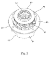
- FIG. 2 is a perspective view of the blower apparatus 1 illustrated in FIG. 1 with the upper cover 10 removed therefrom.
- FIG. 3 is a plan view of the blower apparatus 1.
- FIG. 4 is a vertical cross-sectional view of the blower apparatus 1 taken along line A-A, which passes through a center of the blower apparatus 1, in FIG. 3 . Parallel oblique lines for details of sections of the blower apparatus 1 are omitted.
- an interior space of the blower apparatus 1 is defined by the upper cover 10, the lower cover 20, and a bottom cover 30, which is attached to the lower cover 20 to cover a lower surface of the lower cover 20.
- the blower apparatus 1 further includes the impeller 40, which is defined by a centrifugal impeller, and the motor portion 50, which has a central axis extending in the vertical direction, in the interior space.
- the impeller 40 is arranged above the motor portion 50, is joined to a rotating portion of the motor portion 50, and is arranged to rotate to suck a gas from above and send the gas radially outward.
- the rotating portion of the motor portion 50 to which the impeller 40 is joined is a rotating shaft 51.
- the upper cover 10 includes the impeller cover portion 14 and the cover body portion 18 as described above, and the impeller 40 is covered with the impeller cover portion 14.
- the impeller cover portion 14 includes an inner circumferential surface arranged to cover an outer circumference of the impeller 40 and an upper side of an outer edge portion of the impeller 40, and further includes the air inlet 12 defined in a center thereof.
- the impeller cover portion 14 includes a cylindrical outer circumferential portion arranged to cover the outer circumference of the impeller 40, and an upper surface portion arranged to cover the upper side of the outer edge portion of the impeller 40, and further includes the air inlet 12, which is defined in a center of the upper surface portion.
- the impeller 40 includes a base plate 41, a plurality of rotor blades 42, and a shroud 43 joined to one another.
- the base plate 41 is in the shape of a circular plate.
- the rotor blades 42 are arranged in a circumferential direction on an upper surface of the base plate 41.
- the shroud 43 is in the shape of a curved cone, and includes an opening defined in a central portion thereof.
- An upper end portion of the rotating shaft 51 of the motor portion 50 is joined to a central portion of the base plate 41, so that the impeller 40 is attached to the rotating portion of the motor portion 50.
- the opening defined in the central portion of the shroud 43 of the impeller 40 is arranged to be in communication with the air inlet 12 of the impeller cover portion 14.
- the motor portion 50 is, for example, an inner-rotor brushless motor.
- the motor portion 50 includes a motor housing including an upper housing portion 52 and a lower housing portion 53, and motor components 54 including a rotor portion and a stator portion are accommodated in the motor housing.
- the rotor portion, which is included in the motor components 54, is supported by the rotating shaft 51, while the rotating shaft 51 is rotatably supported by an upper bearing 55 held on a central portion of the upper housing portion 52 and a lower bearing 56 held on a central portion of the bottom cover 30.
- the rotating shaft 51 is caused to rotate together with the rotor portion, which is included in the motor components 54, so that the impeller 40, which is joined to the rotating shaft 51, is also caused to rotate.
- each of the rotor blades 42 of the impeller 40 pushes air in the vicinity of the rotor blade 42 radially outward, generating negative pressure near a radially inner portion of the rotor blade 42, so that external air is sucked in through the air inlet 12.
- the impeller 40 is caused by the motor portion 50 to rotate in, for example, a counterclockwise direction in a plan view.
- the body cover portion which is arranged to cover an outer circumference of the motor portion 50, is defined by the cover body portion 18 of the upper cover 10 and the lower cover 20.
- the body cover portion is joined to the impeller cover portion 14, is arranged to cover the outer circumference of the motor portion 50, and is arranged to define a tubular space 60 between the motor portion 50 and the body cover portion.
- the tubular space 60 is defined between an inner circumferential surface of the body cover portion and an outer circumferential surface of the motor portion 50.
- An upper portion of the tubular space 60 is in communication with a space radially outside of the impeller 40 inside the impeller cover portion 14.
- Each of the air outlets 22 of the lower cover 20 faces a lower portion of the tubular space 60.
- An inner circumferential surface of the cover body portion 18 is a curved surface whose diameter increases with increasing height, while an inner circumferential surface of the lower cover 20 is substantially cylindrical from an upper portion to a middle portion thereof, but is curved at a lower portion thereof, slightly increasing in diameter with decreasing height.
- a radial gap in the tubular space 60 is widest at a top thereof, gradually decreases in width toward a middle portion thereof, and then gradually increases in width from the middle portion toward a bottom thereof.
- a position at which the radial gap in the tubular space 60 is narrow corresponds to, for example, a boundary between a curved portion and a straight portion of each of the plurality of guide vanes 70, which will be described below.
- the plurality of guide vanes 70 are arranged at regular intervals in the circumferential direction in the tubular space 60. Each of the guide vanes 70 is arranged to extend in a radial direction between the inner circumferential surface of the body cover portion and the outer circumferential surface of the motor portion 50, and the guide vanes 70 are arranged to define an air channel which guides a gas sent from the impeller 40 downward.
- the plurality of guide vanes 70 are integrally defined with the upper housing portion 52.
- Each of the guide vanes 70 includes a curved portion 71 arranged at an upper portion thereof, and a straight portion 72 continuous with the curved portion 71 and arranged to extend axially downward therefrom.
- each guide vane 70 is curved in a direction opposite to a rotation direction of the impeller 40 with increasing height. That is, rotation of the impeller 40 causes an air current whirling in the same direction as the rotation direction of the impeller 40, and the curved shape of the curved portion 71 is defined so that the above air current can be smoothly taken in and guided into a downward flow, and the air channel is defined so as to guide the whirling air current sent from the impeller 40 downward.
- a downstream surface of each curved portion 71 with respect to the rotation direction of the impeller 40 includes at least two curved surfaces continuous with each other.
- An upper one of the at least two curved surfaces of the curved portion 71 is arranged to have a radius of curvature greater than a radius of curvature of a lower one of the at least two curved surfaces.
- FIG. 6 corresponds to an upstream side with respect to the rotation direction of the impeller 40, while a right-hand side of FIG. 6 corresponds to a downstream side with respect to the rotation direction of the impeller 40.
- two curved surfaces 71x1 and 71x2 which have different radii of curvature are continuously defined on the downstream side of the curved portion 71 of each guide vane 70 with respect to the rotation direction of the impeller 40.
- a radius of curvature Rx1 of the upper curved surface 71x1 is greater than a radius of curvature Rx2 of the lower curved surface 71x2 (Rx1 > Rx2).
- a curved surface having a radius of curvature smaller than the radius of curvature of the upper curved surface on the downstream side of the curved portion 71 with respect to the rotation direction is defined.
- a curved surface 71y1 having a radius of curvature Ry1 smaller than that of the curved surface 71x1 is defined (Rx1 > Ry1).
- a center of the curved surface on the upstream side of the curved portion 71 with respect to the rotation direction is located upstream, with respect to the rotation direction, of a center of the upper curved surface on the downstream side of the curved portion 71 with respect to the rotation direction.
- a center y1 of the curved surface 71y1 is located upstream of a center x1 of the curved surface 71x1 with respect to the rotation direction of the impeller 40.
- each guide vane 70 with respect to the rotation direction of the impeller 40 On the downstream side of the straight portion 72 of each guide vane 70 with respect to the rotation direction of the impeller 40 are defined a flat surface 72x1 continuous with the curved surface 71x2, and a slanting surface 72x2 arranged below the flat surface 72x1 and arranged to slant toward the upstream side with respect to the rotation direction of the impeller 40 with decreasing height. Meanwhile, on the upstream side of the straight portion 72 with respect to the rotation direction are defined a flat surface 72y1 continuous with the curved surface 71y1, and a slanting surface 72y2 arranged below the flat surface 72y1 and arranged to slant toward the downstream side with respect to the rotation direction with decreasing height.
- Each of the plurality of guide vanes 70 is arranged to axially overlap in part with an adjacent one of the guide vanes 70.
- a tip portion of the curved portion 71 of each guide vane 70 is arranged to axially overlap with both the curved portion 70 and the straight portion 72 of an adjacent one of the guide vanes 70 which is arranged upstream thereof with respect to the rotation direction of the impeller 40.
- the above structure allows the guide vanes 70 to more efficiently take in air sent from the impeller 40 and guide the air into the downward flow.
- An intervane space between every adjacent ones of the plurality of guide vanes 70, which are arranged at regular intervals in the circumferential direction in the tubular space 60, is arranged to be narrowest at a tip of the curved portion 71 of the guide vane 70 and widest at a lower end of the straight portion 72 of the guide vane 70 when measured in a direction perpendicular to a direction in which the gas flows through the air channel between the adjacent guide vanes 70.
- the impeller 40 is caused to rotate to take in external air through the air inlet 12 of the impeller cover portion 14 and discharge the air radially outward as a swirl flow, so that the air is guided to an inner surface of the cylindrical outer circumferential portion of the impeller cover portion 14. Further, the air current sent from the impeller 40 is guided into the tubular space 60 to pass through the intervane space between the adjacent guide vanes 70, so that the swirl flow is guided into an axial flow.
- the swirl flow sent from the impeller 40 is effectively taken into the intervane space between the adjacent guide vanes 70, and since the thickness of the curved portion 71 is arranged to vary along the direction in which the air flows, that is, since the shape of the curved portion 71 is designed such that the two curved surfaces 71x1 and 71x2 having different radii of curvature are defined on the downstream side of each guide vane 71 with respect to the rotation direction of the impeller 40 and the curved surface 71y1 is defined on the upstream side of the curved portion 71 with respect to the rotation direction, the air flow can be efficiently guided along surfaces of the guide vanes 70 without occurrence of a separation of the air flow.
- the radial gap in the tubular space 60 is narrowest in the vicinity of the boundary between the curved portion 71 and the straight portion 72 of each guide vane 70, air which has flowed into the tubular space 60 is compressed in the vicinity of the boundary between the curved portion 71 and the straight portion 72 due to an increase in channel resistance, and the air is thereafter decompressed to form a gentle air flow due to a gradual increase in the width of the radial gap as the air travels downward along the straight portion 72, completing discharge of the air without occurrence of a separation of the air flow.
- the above effect is promoted by a gradual increase in the width of the intervane space between the adjacent guide vanes 70 at a lower portion of the straight portion 72.
- each of the plurality of guide vanes 70 arranged in the tubular space 60 is arranged to axially overlap in part with an adjacent one of the guide vanes 70.
- each of the plurality of guide vanes 70 may not necessarily be arranged to axially overlap with an adjacent one of the guide vanes 70.
- the structure of a resin molding mold for the guide vanes 70 can be simplified.
- the guide vanes 70 are arranged to axially overlap in part with one another, it may be so arranged that alternate ones of the plurality of guide vanes 70 are integrally defined with the upper housing portion 52 while the other alternate ones of the guide vanes 70 are integrally defined with the cover body portion 18 of the upper cover 10.
- each guide vane 70 of each of the plurality of guide vanes 70 arranged in the tubular space 60 is arranged to extend axially downward, this is not essential to the present invention.
- the straight portion 72 may be arranged to extend downward and be angled with respect to the axial direction toward the direction in which the curved portion 71 is curved.
- the impeller 40 caused by the motor portion 50 to rotate is a centrifugal impeller, this is not essential to the present invention.
- a mixed flow impeller may alternatively be used.
- the mixed flow impeller is joined to the rotating portion of the motor portion, and is caused by the motor portion to rotate to suck a gas from above and send the gas radially outward while guiding the gas along slanting surfaces of the mixed flow impeller.
- blower apparatus is used in a vacuum cleaner which utilizes air sucked by the blower apparatus, this is not essential to the present invention.
- a blower apparatus according to a preferred embodiment of the present invention may be used in, for example, a hair drier which utilizes air sent out by the blower apparatus.
- Blower apparatuses are suitable for use in, for example, electric vacuum cleaners, hair driers, and the like.
Landscapes
- Engineering & Computer Science (AREA)
- Mechanical Engineering (AREA)
- General Engineering & Computer Science (AREA)
- Structures Of Non-Positive Displacement Pumps (AREA)
Abstract
Description
- The present invention relates to an electric blower apparatus. The blower apparatus is installed in, for example, a vacuum cleaner.
- Blower apparatuses installed in vacuum cleaners are required to have a high static pressure. Such blower apparatuses are disclosed in, for example,
JP-A 2010-281232 JP-A 2011-80427 - Each of the plate-shaped air guides, which are arranged to downwardly guide air sent radially outward from the impeller, includes a curved portion which is inclined to guide the flow of air, but when the impeller rotates at a high speed, a separation of the air may occur at a surface of any air guide to cause noise. A reduction in noise is particularly important when the blower apparatus is used in a consumer product, such as, for example, a vacuum cleaner.
- It is an object of the present invention to reduce noise of a blower apparatus while maintaining a high static pressure of the blower apparatus.
- This object is achieved by a blower apparatus according to
claim 1. - A blower apparatus according to a preferred embodiment of the present invention includes a motor portion having a central axis extending in a vertical direction, an impeller, an impeller cover portion, a body cover portion, and a plurality of guide vanes. The impeller is arranged above the motor portion, is joined to a rotating portion of the motor portion, and is arranged to rotate to suck a gas from above and send the gas radially outward. The impeller cover portion includes an inner circumferential surface arranged to cover an outer circumference of the impeller and an upper side of an outer edge portion of the impeller, and further includes an air inlet defined in a center thereof. The body cover portion is joined to the impeller cover portion, is arranged to cover an outer circumference of the motor portion, and is arranged to define a tubular space between the motor portion and the body cover portion. The plurality of guide vanes are arranged at regular intervals in a circumferential direction in the tubular space, and are arranged to define an air channel which guides the gas sent from the impeller downward. Each guide vane is arranged to extend in a radial direction between an inner circumferential surface of the body cover portion and an outer circumferential surface of the motor portion. Each of the plurality of guide vanes includes a curved portion arranged at an upper portion thereof, and a straight portion continuous with the curved portion and arranged to extend downward therefrom. The curved portion is curved in a direction opposite to a rotation direction of the impeller with increasing height. A downstream surface of the curved portion with respect to the rotation direction includes at least two curved surfaces continuous with each other. An upper one of the at least two curved surfaces of the curved portion has a radius of curvature greater than a radius of curvature of a lower one of the at least two curved surfaces.
- The above preferred embodiment of the present invention is able to reduce noise of the blower apparatus while maintaining a high static pressure of the blower apparatus.
- The above and other elements, features, steps, characteristics and advantages of the present invention will become more apparent from the following detailed description of the preferred embodiments with reference to the attached drawings.
-
-
FIG. 1 is a perspective view of a blower apparatus according to a preferred embodiment of the present invention. -
FIG. 2 is a perspective view of the blower apparatus illustrated inFIG. 1 with an upper cover removed therefrom. -
FIG. 3 is a plan view of the blower apparatus illustrated inFIG. 1 . -
FIG. 4 is a cross-sectional view of the blower apparatus taken along line A-A inFIG. 3 . -
FIG. 5 is a cross-sectional view of the blower apparatus taken along line B-B inFIG. 3 . -
FIG. 6 is a diagram for explaining guide vanes illustrated inFIG. 5 according to a preferred embodiment of the present invention. - Hereinafter, a blower apparatus according to a preferred embodiment of the present invention will be described with reference to the accompanying drawings. It is assumed herein that a direction parallel or substantially parallel to a central axis of a blower apparatus is referred to by the term "axial direction", "axial", or "axially", that directions perpendicular or substantially perpendicular to the central axis of the blower apparatus are each referred to by the term "radial direction", "radial", or "radially", and that a direction along a circular arc centered on the central axis of the blower apparatus is referred to by the term "circumferential direction", "circumferential", or "circumferentially". It is also assumed herein that an axial direction is a vertical direction, and that a side on which an impeller is arranged with respect to a motor portion is defined as an upper side. The shape of each member or portion and relative positions of different members or portions will be described based on the above assumptions. It should be noted, however, that the above definitions of the vertical direction and the upper side are not meant to restrict in any way the orientation of a blower apparatus according to any preferred embodiment of the present invention when in use.
-
FIG. 1 is a perspective view illustrating an overall structure of ablower apparatus 1 according to a preferred embodiment of the present invention. Theblower apparatus 1 includes amotor portion 50, animpeller 40, animpeller cover portion 14, a body cover portion, and a plurality ofguide vanes 70. Theblower apparatus 1 includes anupper cover 10 and alower cover 20 arranged at an outer portion thereof. Theupper cover 10 includes theimpeller cover portion 14 and acover body portion 18. Theimpeller cover portion 14 is made of a metal, is in the shape of a cap, and includes anair inlet 12 defined in a central portion of an upper surface thereof. Thecover body portion 18 includes a cylindrical portion to which a cylindrical portion of theimpeller cover portion 14 is fitted from radially outside, and anupper flange portion 16 is defined integrally with a lower end of the cylindrical portion of thecover body portion 18. Thecover body portion 18 is defined by a resin-molded article. Thelower cover 20 is defined by a resin-molded article, and includes a lowercylindrical portion 24 and alower flange portion 26. A plurality ofair outlets 22 are defined in a lower portion of an outer circumference of the lowercylindrical portion 24. Thelower flange portion 26 is defined integrally with an upper end of the lowercylindrical portion 24. Theupper flange portion 16 and thelower flange portion 26, which are arranged above and below, respectively, are joined to each other throughscrews 28, so that the upper andlower covers upper flange portion 16, while screw holes are defined at several circumferential positions in thelower flange portion 26 such that the screw holes are opposed to the screw insert holes. Thescrews 28 are screwed into the screw holes through the screw insert holes. -
FIG. 2 is a perspective view of theblower apparatus 1 illustrated inFIG. 1 with theupper cover 10 removed therefrom.FIG. 3 is a plan view of theblower apparatus 1.FIG. 4 is a vertical cross-sectional view of theblower apparatus 1 taken along line A-A, which passes through a center of theblower apparatus 1, inFIG. 3 . Parallel oblique lines for details of sections of theblower apparatus 1 are omitted. - Referring to
FIG. 4 , an interior space of theblower apparatus 1 is defined by theupper cover 10, thelower cover 20, and abottom cover 30, which is attached to thelower cover 20 to cover a lower surface of thelower cover 20. Theblower apparatus 1 further includes theimpeller 40, which is defined by a centrifugal impeller, and themotor portion 50, which has a central axis extending in the vertical direction, in the interior space. Theimpeller 40 is arranged above themotor portion 50, is joined to a rotating portion of themotor portion 50, and is arranged to rotate to suck a gas from above and send the gas radially outward. According to the present preferred embodiment, the rotating portion of themotor portion 50 to which theimpeller 40 is joined is a rotatingshaft 51. - The
upper cover 10 includes theimpeller cover portion 14 and thecover body portion 18 as described above, and theimpeller 40 is covered with theimpeller cover portion 14. Theimpeller cover portion 14 includes an inner circumferential surface arranged to cover an outer circumference of theimpeller 40 and an upper side of an outer edge portion of theimpeller 40, and further includes theair inlet 12 defined in a center thereof. In more detail, theimpeller cover portion 14 includes a cylindrical outer circumferential portion arranged to cover the outer circumference of theimpeller 40, and an upper surface portion arranged to cover the upper side of the outer edge portion of theimpeller 40, and further includes theair inlet 12, which is defined in a center of the upper surface portion. Theimpeller 40 includes abase plate 41, a plurality ofrotor blades 42, and ashroud 43 joined to one another. Thebase plate 41 is in the shape of a circular plate. Therotor blades 42 are arranged in a circumferential direction on an upper surface of thebase plate 41. Theshroud 43 is in the shape of a curved cone, and includes an opening defined in a central portion thereof. An upper end portion of therotating shaft 51 of themotor portion 50 is joined to a central portion of thebase plate 41, so that theimpeller 40 is attached to the rotating portion of themotor portion 50. The opening defined in the central portion of theshroud 43 of theimpeller 40 is arranged to be in communication with theair inlet 12 of theimpeller cover portion 14. - The
motor portion 50 is, for example, an inner-rotor brushless motor. Themotor portion 50 includes a motor housing including anupper housing portion 52 and alower housing portion 53, andmotor components 54 including a rotor portion and a stator portion are accommodated in the motor housing. The rotor portion, which is included in themotor components 54, is supported by the rotatingshaft 51, while the rotatingshaft 51 is rotatably supported by anupper bearing 55 held on a central portion of theupper housing portion 52 and alower bearing 56 held on a central portion of thebottom cover 30. Once themotor portion 50 is driven, the rotatingshaft 51 is caused to rotate together with the rotor portion, which is included in themotor components 54, so that theimpeller 40, which is joined to therotating shaft 51, is also caused to rotate. Rotation of each of therotor blades 42 of theimpeller 40 pushes air in the vicinity of therotor blade 42 radially outward, generating negative pressure near a radially inner portion of therotor blade 42, so that external air is sucked in through theair inlet 12. Theimpeller 40 is caused by themotor portion 50 to rotate in, for example, a counterclockwise direction in a plan view. - The body cover portion, which is arranged to cover an outer circumference of the
motor portion 50, is defined by thecover body portion 18 of theupper cover 10 and thelower cover 20. The body cover portion is joined to theimpeller cover portion 14, is arranged to cover the outer circumference of themotor portion 50, and is arranged to define atubular space 60 between themotor portion 50 and the body cover portion. In more detail, thetubular space 60 is defined between an inner circumferential surface of the body cover portion and an outer circumferential surface of themotor portion 50. An upper portion of thetubular space 60 is in communication with a space radially outside of theimpeller 40 inside theimpeller cover portion 14. Each of theair outlets 22 of thelower cover 20 faces a lower portion of thetubular space 60. An inner circumferential surface of thecover body portion 18 is a curved surface whose diameter increases with increasing height, while an inner circumferential surface of thelower cover 20 is substantially cylindrical from an upper portion to a middle portion thereof, but is curved at a lower portion thereof, slightly increasing in diameter with decreasing height. As a result, a radial gap in thetubular space 60 is widest at a top thereof, gradually decreases in width toward a middle portion thereof, and then gradually increases in width from the middle portion toward a bottom thereof. Note that a position at which the radial gap in thetubular space 60 is narrow corresponds to, for example, a boundary between a curved portion and a straight portion of each of the plurality ofguide vanes 70, which will be described below. - The plurality of
guide vanes 70 are arranged at regular intervals in the circumferential direction in thetubular space 60. Each of the guide vanes 70 is arranged to extend in a radial direction between the inner circumferential surface of the body cover portion and the outer circumferential surface of themotor portion 50, and theguide vanes 70 are arranged to define an air channel which guides a gas sent from theimpeller 40 downward. The plurality ofguide vanes 70 are integrally defined with theupper housing portion 52. Each of the guide vanes 70 includes acurved portion 71 arranged at an upper portion thereof, and astraight portion 72 continuous with thecurved portion 71 and arranged to extend axially downward therefrom. Thecurved portion 71 of eachguide vane 70 is curved in a direction opposite to a rotation direction of theimpeller 40 with increasing height. That is, rotation of theimpeller 40 causes an air current whirling in the same direction as the rotation direction of theimpeller 40, and the curved shape of thecurved portion 71 is defined so that the above air current can be smoothly taken in and guided into a downward flow, and the air channel is defined so as to guide the whirling air current sent from theimpeller 40 downward. - A downstream surface of each
curved portion 71 with respect to the rotation direction of theimpeller 40 includes at least two curved surfaces continuous with each other. An upper one of the at least two curved surfaces of thecurved portion 71 is arranged to have a radius of curvature greater than a radius of curvature of a lower one of the at least two curved surfaces. A more specific explanation will be provided below with reference toFIGS. 5 and6 .FIG. 5 illustrates theblower apparatus 1 when theupper cover 10 and thelower cover 20 are cut along line B-B inFIG. 3 .FIG. 6 illustrates two of theguide vanes 70 illustrated inFIG. 5 in an enlarged form. A left-hand side ofFIG. 6 corresponds to an upstream side with respect to the rotation direction of theimpeller 40, while a right-hand side ofFIG. 6 corresponds to a downstream side with respect to the rotation direction of theimpeller 40. As illustrated inFIG. 6 , two curved surfaces 71x1 and 71x2 which have different radii of curvature are continuously defined on the downstream side of thecurved portion 71 of eachguide vane 70 with respect to the rotation direction of theimpeller 40. A radius of curvature Rx1 of the upper curved surface 71x1 is greater than a radius of curvature Rx2 of the lower curved surface 71x2 (Rx1 > Rx2). Meanwhile, on the upstream side of thecurved portion 71 with respect to the rotation direction, a curved surface having a radius of curvature smaller than the radius of curvature of the upper curved surface on the downstream side of thecurved portion 71 with respect to the rotation direction is defined. Specifically, on the upstream side of thecurved portion 71 of eachguide vane 70 with respect to the rotation direction of theimpeller 40, a curved surface 71y1 having a radius of curvature Ry1 smaller than that of the curved surface 71x1 is defined (Rx1 > Ry1). A center of the curved surface on the upstream side of thecurved portion 71 with respect to the rotation direction is located upstream, with respect to the rotation direction, of a center of the upper curved surface on the downstream side of thecurved portion 71 with respect to the rotation direction. Specifically, a center y1 of the curved surface 71y1 is located upstream of a center x1 of the curved surface 71x1 with respect to the rotation direction of theimpeller 40. - On the downstream side of the
straight portion 72 of eachguide vane 70 with respect to the rotation direction of theimpeller 40 are defined a flat surface 72x1 continuous with the curved surface 71x2, and a slanting surface 72x2 arranged below the flat surface 72x1 and arranged to slant toward the upstream side with respect to the rotation direction of theimpeller 40 with decreasing height. Meanwhile, on the upstream side of thestraight portion 72 with respect to the rotation direction are defined a flat surface 72y1 continuous with the curved surface 71y1, and a slanting surface 72y2 arranged below the flat surface 72y1 and arranged to slant toward the downstream side with respect to the rotation direction with decreasing height. - Each of the plurality of
guide vanes 70 is arranged to axially overlap in part with an adjacent one of the guide vanes 70. Specifically, referring toFIG. 5 , a tip portion of thecurved portion 71 of eachguide vane 70 is arranged to axially overlap with both thecurved portion 70 and thestraight portion 72 of an adjacent one of theguide vanes 70 which is arranged upstream thereof with respect to the rotation direction of theimpeller 40. The above structure allows theguide vanes 70 to more efficiently take in air sent from theimpeller 40 and guide the air into the downward flow. - An intervane space between every adjacent ones of the plurality of
guide vanes 70, which are arranged at regular intervals in the circumferential direction in thetubular space 60, is arranged to be narrowest at a tip of thecurved portion 71 of theguide vane 70 and widest at a lower end of thestraight portion 72 of theguide vane 70 when measured in a direction perpendicular to a direction in which the gas flows through the air channel between the adjacent guide vanes 70. - Once the
motor portion 50 is driven in theblower apparatus 1 having the above-described structure, theimpeller 40 is caused to rotate to take in external air through theair inlet 12 of theimpeller cover portion 14 and discharge the air radially outward as a swirl flow, so that the air is guided to an inner surface of the cylindrical outer circumferential portion of theimpeller cover portion 14. Further, the air current sent from theimpeller 40 is guided into thetubular space 60 to pass through the intervane space between theadjacent guide vanes 70, so that the swirl flow is guided into an axial flow. - At this time, because of the
curved portion 71 arranged at the upper portion of eachguide vane 70, the swirl flow sent from theimpeller 40 is effectively taken into the intervane space between theadjacent guide vanes 70, and since the thickness of thecurved portion 71 is arranged to vary along the direction in which the air flows, that is, since the shape of thecurved portion 71 is designed such that the two curved surfaces 71x1 and 71x2 having different radii of curvature are defined on the downstream side of eachguide vane 71 with respect to the rotation direction of theimpeller 40 and the curved surface 71y1 is defined on the upstream side of thecurved portion 71 with respect to the rotation direction, the air flow can be efficiently guided along surfaces of theguide vanes 70 without occurrence of a separation of the air flow. In particular, it has been observed that, when the radii of curvature Rx1 and Rx2 of, respectively, the two curved surfaces 71x1 and 71x2 on the downstream side of thecurved portion 71 with respect to the rotation direction meet the relationship Rx1 > Rx2, and the radius of curvature Ry1 of the curved surface 71y1 on the upstream side of thecurved portion 71 with respect to the rotation direction and the radius of curvature Rx1 of the curved surface 71x1 meet the relationship Rx1 > Ry1, the air flow in thetubular space 60 is improved to achieve a significant improvement in efficiency. - In addition, because the radial gap in the
tubular space 60 is narrowest in the vicinity of the boundary between thecurved portion 71 and thestraight portion 72 of eachguide vane 70, air which has flowed into thetubular space 60 is compressed in the vicinity of the boundary between thecurved portion 71 and thestraight portion 72 due to an increase in channel resistance, and the air is thereafter decompressed to form a gentle air flow due to a gradual increase in the width of the radial gap as the air travels downward along thestraight portion 72, completing discharge of the air without occurrence of a separation of the air flow. In particular, the above effect is promoted by a gradual increase in the width of the intervane space between theadjacent guide vanes 70 at a lower portion of thestraight portion 72. - While a preferred embodiment of the present invention has been described above, it will be understood that the present invention is not limited to the above-described preferred embodiment, and that a variety of modifications are possible without departing from the scope of the present invention as claimed below.
- In the above-described preferred embodiment, each of the plurality of
guide vanes 70 arranged in thetubular space 60 is arranged to axially overlap in part with an adjacent one of the guide vanes 70. Note, however, that each of the plurality ofguide vanes 70 may not necessarily be arranged to axially overlap with an adjacent one of the guide vanes 70. When theguide vanes 70 do not axially overlap with one another, the structure of a resin molding mold for theguide vanes 70 can be simplified. Meanwhile, in the case where theguide vanes 70 are arranged to axially overlap in part with one another, it may be so arranged that alternate ones of the plurality ofguide vanes 70 are integrally defined with theupper housing portion 52 while the other alternate ones of theguide vanes 70 are integrally defined with thecover body portion 18 of theupper cover 10. - Further, although, in the above-described preferred embodiment, the
straight portion 72 of each of the plurality ofguide vanes 70 arranged in thetubular space 60 is arranged to extend axially downward, this is not essential to the present invention. Thestraight portion 72 may be arranged to extend downward and be angled with respect to the axial direction toward the direction in which thecurved portion 71 is curved. When eachguide vane 70 is shaped in such a manner, an effect similar to the effect of the above-described preferred embodiment can be obtained even if the length of thecurved portion 71 is reduced, and therefore, the length of eachguide vane 70 can be reduced to achieve a reduction in the size of theblower apparatus 1 as a whole. - Although, in the above-described preferred embodiment, the
impeller 40 caused by themotor portion 50 to rotate is a centrifugal impeller, this is not essential to the present invention. A mixed flow impeller may alternatively be used. In this case, the mixed flow impeller is joined to the rotating portion of the motor portion, and is caused by the motor portion to rotate to suck a gas from above and send the gas radially outward while guiding the gas along slanting surfaces of the mixed flow impeller. - Although the blower apparatus according to the above-described preferred embodiment of the present invention is used in a vacuum cleaner which utilizes air sucked by the blower apparatus, this is not essential to the present invention. A blower apparatus according to a preferred embodiment of the present invention may be used in, for example, a hair drier which utilizes air sent out by the blower apparatus.
- Blower apparatuses according to preferred embodiments of the present invention are suitable for use in, for example, electric vacuum cleaners, hair driers, and the like.
- Features of the above-described preferred embodiments and the modifications thereof may be combined appropriately as long as no conflict arises.
- While preferred embodiments of the present invention have been described above, it is to be understood that variations and modifications will be apparent to those skilled in the art without departing from the scope and spirit of the present invention. The scope of the present invention, therefore, is to be determined solely by the following claims.
Claims (8)
- A blower apparatus comprising:a motor portion (50) having a central axis extending in a vertical direction;an impeller (40) arranged above the motor portion (50), joined to a rotating portion of the motor portion (50), and arranged to rotate to suck a gas from above and send the gas radially outward;an impeller cover portion (14) including an inner circumferential surface arranged to cover an outer circumference of the impeller (40) and an upper side of an outer edge portion of the impeller (40), and further including an air inlet (12) defined in a center thereof;a body cover portion joined to the impeller cover portion (14), arranged to cover an outer circumference of the motor portion (50), and arranged to define a tubular space (60) between the motor portion (50) and the body cover portion; anda plurality of guide vanes (70) arranged at regular intervals in a circumferential direction in the tubular space (60), and arranged to define an air channel which guides the gas sent from the impeller (40) downward, each guide vane (70) being arranged to extend in a radial direction between an inner circumferential surface of the body cover portion and an outer circumferential surface of the motor portion (50); whereineach of the plurality of guide vanes (70) includes a curved portion (71) arranged at an upper portion thereof, and a straight portion (72) continuous with the curved portion (71) and arranged to extend downward therefrom, the curved portion (71) being curved in a direction opposite to a rotation direction of the impeller (40) with increasing height, a downstream surface of the curved portion (71) with respect to the rotation direction including at least two curved surfaces (71x1, 71x2) continuous with each other, an upper one (71x1) of the at least two curved surfaces (71x1, 71x2) having a radius (Rx1) of curvature greater than a radius (Rx2) of curvature of a lower one (71x2) of the at least two curved surfaces (71x1, 71x2).
- The blower apparatus according to claim 1, wherein, on an upstream side of the curved portion (71) of each guide vane (70) with respect to the rotation direction, a curved surface (71y1) having a radius (Ry1) of curvature smaller than the radius of curvature (Rx1) of the upper one (71x1) of the at least two curved surfaces (71x1, 71x2) on the downstream side of the curved portion (71) with respect to the rotation direction is defined.
- The blower apparatus according to claim 2, wherein a center of the curved surface (71y1) on the upstream side of the curved portion (71) with respect to the rotation direction is located upstream, with respect to the rotation direction, of a center of the upper one (71x1) of the at least two curved surfaces (71x1, 71x2) on the downstream side of the curved portion (71) with respect to the rotation direction.
- The blower apparatus according to any one of claims 1 to 3, wherein each of the plurality of guide vanes (70) is arranged to axially overlap in part with an adjacent one of the guide vanes (70).
- The blower apparatus according to any one of claims 1 to 4, wherein a radial gap in the tubular space (60) is widest at a top thereof, gradually decreases in width toward a middle portion thereof, and then gradually increases in width from the middle portion toward a bottom thereof.
- The blower apparatus according to any one of claims 1 to 5, wherein an intervane space between every adjacent ones of the plurality of guide vanes (70) is arranged to be narrow at a tip of the curved portion (71) of the guide vane (70) and wide at a lower end of the straight portion (72) of the guide vane (70) when measured in a direction perpendicular to a direction in which the gas flows through the air channel.
- The blower apparatus according to any one of claims 1 to 6, wherein a surface of the straight portion (72) of each guide vane (70) on the upstream side with respect to the rotation direction includes a slanting surface (72y2) arranged to slant toward the downstream side with respect to the rotation direction with decreasing height.
- The blower apparatus according to any one of claims 1 to 7, wherein a surface of the straight portion (72) of each guide vane (70) on the downstream side with respect to the rotation direction includes a slanting surface (72x2) arranged to slant toward the upstream side with respect to the rotation direction with decreasing height.
Applications Claiming Priority (1)
| Application Number | Priority Date | Filing Date | Title |
|---|---|---|---|
| JP2014220914 | 2014-10-30 |
Publications (1)
| Publication Number | Publication Date |
|---|---|
| EP3015713A1 true EP3015713A1 (en) | 2016-05-04 |
Family
ID=53487229
Family Applications (2)
| Application Number | Title | Priority Date | Filing Date |
|---|---|---|---|
| EP15173114.8A Withdrawn EP3015713A1 (en) | 2014-10-30 | 2015-06-22 | Blower apparatus |
| EP15854220.9A Withdrawn EP3214318A4 (en) | 2014-10-30 | 2015-10-30 | Blower device and cleaner |
Family Applications After (1)
| Application Number | Title | Priority Date | Filing Date |
|---|---|---|---|
| EP15854220.9A Withdrawn EP3214318A4 (en) | 2014-10-30 | 2015-10-30 | Blower device and cleaner |
Country Status (5)
| Country | Link |
|---|---|
| US (2) | US10184487B2 (en) |
| EP (2) | EP3015713A1 (en) |
| JP (2) | JPWO2016068280A1 (en) |
| CN (2) | CN205154686U (en) |
| WO (2) | WO2016068280A1 (en) |
Cited By (2)
| Publication number | Priority date | Publication date | Assignee | Title |
|---|---|---|---|---|
| US11025122B2 (en) * | 2017-02-01 | 2021-06-01 | Lg Electronics Inc. | Fan motor |
| CN115199575A (en) * | 2022-08-02 | 2022-10-18 | 淮安璟凌电子科技有限公司 | Special blower for semiconductor epitaxy equipment |
Families Citing this family (23)
| Publication number | Priority date | Publication date | Assignee | Title |
|---|---|---|---|---|
| EP3015713A1 (en) * | 2014-10-30 | 2016-05-04 | Nidec Corporation | Blower apparatus |
| GB2545269B (en) * | 2015-12-11 | 2018-02-28 | Dyson Technology Ltd | An electric motor |
| US20180209442A1 (en) * | 2016-06-30 | 2018-07-26 | Nidec Corporation | Blower device and cleaner |
| CN106499670B (en) * | 2016-10-28 | 2017-10-10 | 扬州大学 | Pump installation outlet passage with secondary stator |
| JP2018109400A (en) * | 2016-12-28 | 2018-07-12 | 日本電産株式会社 | Blower and vacuum cleaner provided with the same |
| KR101881247B1 (en) * | 2017-01-16 | 2018-08-17 | 엘지전자 주식회사 | Fan Motor |
| US20180266440A1 (en) * | 2017-03-17 | 2018-09-20 | Nidec Corporation | Blower and vacuum cleaner |
| JP2019024276A (en) * | 2017-07-21 | 2019-02-14 | 日本電産株式会社 | Notor, blower, and cleaner |
| CN106870459B (en) * | 2017-04-28 | 2019-08-16 | 广东威灵电机制造有限公司 | Guide vane wheel assembly and blower with it |
| CN107218251A (en) * | 2017-06-06 | 2017-09-29 | 武汉船用机械有限责任公司 | A kind of pump head device |
| JP2019047669A (en) * | 2017-09-05 | 2019-03-22 | 日本電産株式会社 | Motor module and vacuum cleaner |
| CN107781176B (en) * | 2017-11-30 | 2024-06-25 | 浙江颐顿机电有限公司 | Stacked multi-layer centrifugal fan |
| WO2019167153A1 (en) | 2018-02-28 | 2019-09-06 | 三菱電機株式会社 | Electric blower, electric vacuum cleaner and hand dryer |
| CN108321965B (en) * | 2018-03-26 | 2023-09-19 | 莱克电气股份有限公司 | Brushless vacuum cleaner motor end cover |
| CN208651209U (en) * | 2018-05-31 | 2019-03-26 | 江苏美的清洁电器股份有限公司 | A kind of fan assembly and sweeping robot of sweeping robot |
| JP7318208B2 (en) * | 2019-01-09 | 2023-08-01 | ニデック株式会社 | motors, blowers and vacuum cleaners |
| CN110107510A (en) * | 2019-06-10 | 2019-08-09 | 胜利油田高原石油装备有限责任公司 | A kind of multi-functional mixing pump |
| KR102334621B1 (en) * | 2019-07-10 | 2021-12-03 | 엘지전자 주식회사 | Fan Motor |
| CN112524090B (en) * | 2019-09-19 | 2022-09-20 | 日本电产株式会社 | Air supply device and electromechanical device |
| JP7514668B2 (en) * | 2020-06-29 | 2024-07-11 | 株式会社マキタ | Cleaner |
| CN113757145A (en) * | 2021-09-14 | 2021-12-07 | 杭州贝丰科技有限公司 | fan |
| WO2023097481A1 (en) | 2021-11-30 | 2023-06-08 | 江苏美的清洁电器股份有限公司 | Fan assembly and vacuum cleaner having same |
| CN114738324B (en) * | 2022-04-07 | 2023-09-22 | 北京涵智博雅能源科技有限公司 | Inlet guide vane adjusting device and centrifugal compressor |
Citations (4)
| Publication number | Priority date | Publication date | Assignee | Title |
|---|---|---|---|---|
| US4946348A (en) * | 1989-02-14 | 1990-08-07 | Airflow Research & Manufacturing Corporation | Centrifugal fan with airfoil vanes in annular volute envelope |
| DE19626896A1 (en) * | 1996-07-04 | 1998-01-08 | Mayer Gmbh Geb | Fan, e.g. for cooker extractor hood |
| JP2010281232A (en) | 2009-06-03 | 2010-12-16 | Panasonic Corp | Electric blower and electric vacuum cleaner using the same |
| JP2011080427A (en) | 2009-10-08 | 2011-04-21 | Panasonic Corp | Electric blower and vacuum cleaner using the same |
Family Cites Families (35)
| Publication number | Priority date | Publication date | Assignee | Title |
|---|---|---|---|---|
| DK118475B (en) | 1965-08-02 | 1970-08-24 | Nordisk Ventilator | Radial fan with axial outflow. |
| US4057370A (en) * | 1975-02-04 | 1977-11-08 | Matsushita Electric Industrial Co., Ltd | Electric blower assembly |
| GB2190429B (en) * | 1986-04-14 | 1990-10-17 | Hitachi Ltd | An electric blower |
| JPH04505199A (en) * | 1989-02-14 | 1992-09-10 | エアフロー リサーチ アンド マニュファクチュアリング コーポレーション | Centrifugal blower with airfoil vanes in a circular spiral envelope |
| US4900228A (en) | 1989-02-14 | 1990-02-13 | Airflow Research And Manufacturing Corporation | Centrifugal fan with variably cambered blades |
| JPH0765597B2 (en) * | 1989-03-01 | 1995-07-19 | 株式会社日立製作所 | Electric blower |
| JPH094592A (en) | 1995-06-16 | 1997-01-07 | Hitachi Ltd | Turbo blower |
| JP3569087B2 (en) * | 1996-11-05 | 2004-09-22 | 株式会社日立製作所 | Multistage centrifugal compressor |
| JPH11125198A (en) * | 1997-10-22 | 1999-05-11 | Matsushita Electric Ind Co Ltd | Electric blower |
| JP3747630B2 (en) | 1998-05-25 | 2006-02-22 | 松下電器産業株式会社 | Electric blower |
| EP1325702B1 (en) * | 2002-01-03 | 2010-07-14 | Lg Electronics Inc. | Centrifugal blower for vacuum cleaner |
| GB0328384D0 (en) * | 2003-12-06 | 2004-01-14 | Johnson Electric Sa | Blower motor |
| GB0613796D0 (en) * | 2006-07-12 | 2006-08-23 | Johnson Electric Sa | Blower |
| DE102008014624A1 (en) | 2008-03-17 | 2009-09-24 | Vorwerk & Co. Interholding Gmbh | electric motor |
| JP5048701B2 (en) * | 2009-03-10 | 2012-10-17 | 三菱電機株式会社 | Electric blower and electric vacuum cleaner |
| JP5272862B2 (en) | 2009-04-13 | 2013-08-28 | パナソニック株式会社 | Electric blower and electric vacuum cleaner using the same |
| JP2011052591A (en) | 2009-09-02 | 2011-03-17 | Panasonic Corp | Electric blower and vacuum cleaner using the same |
| JP2012255352A (en) | 2011-06-08 | 2012-12-27 | Panasonic Corp | Electric blower and vacuum cleaner using the same |
| JP2012255412A (en) | 2011-06-10 | 2012-12-27 | Panasonic Corp | Electric blower and vacuum cleaner using the same |
| JP2012255413A (en) | 2011-06-10 | 2012-12-27 | Panasonic Corp | Electric blower and electric vacuum cleaner using the same |
| EP2739857B1 (en) | 2011-08-05 | 2017-04-26 | ResMed Motor Technologies Inc. | Blower |
| WO2013053920A1 (en) * | 2011-10-13 | 2013-04-18 | Aktiebolaget Electrolux | Vacuum cleaner |
| US8807930B2 (en) | 2011-11-01 | 2014-08-19 | United Technologies Corporation | Non axis-symmetric stator vane endwall contour |
| DE102013104849A1 (en) | 2012-06-20 | 2013-12-24 | Vorwerk & Co. Interholding Gmbh | Fan wheel and electric motor |
| JP6585873B2 (en) | 2013-08-09 | 2019-10-02 | 日本電産株式会社 | Blower and vacuum cleaner |
| JP2015095997A (en) * | 2013-11-13 | 2015-05-18 | 日本電産株式会社 | Motor |
| JP3191384U (en) | 2014-04-09 | 2014-06-19 | 陳玉沛 | Centrifugal impeller |
| JP6417771B2 (en) * | 2014-07-31 | 2018-11-07 | 日本電産株式会社 | Electric blower |
| EP3015713A1 (en) * | 2014-10-30 | 2016-05-04 | Nidec Corporation | Blower apparatus |
| US20180100517A1 (en) * | 2015-04-28 | 2018-04-12 | Nidec Corporation | Centrifugal blower and vacuum cleaner |
| CN107614891B (en) * | 2015-05-25 | 2019-03-15 | 日本电产株式会社 | Air supply unit and vacuum cleaner |
| JP2016223432A (en) * | 2015-05-29 | 2016-12-28 | 日本電産株式会社 | Impeller, blower module and cleaner |
| JP6288373B2 (en) * | 2015-05-29 | 2018-03-07 | 日本電産株式会社 | Blower and vacuum cleaner |
| WO2016194255A1 (en) * | 2015-05-29 | 2016-12-08 | 日本電産株式会社 | Blower device and cleaner |
| JP6658750B2 (en) * | 2015-05-29 | 2020-03-04 | 日本電産株式会社 | Blowers and vacuum cleaners |
-
2015
- 2015-06-22 EP EP15173114.8A patent/EP3015713A1/en not_active Withdrawn
- 2015-10-30 US US15/522,953 patent/US10184487B2/en not_active Expired - Fee Related
- 2015-10-30 EP EP15854220.9A patent/EP3214318A4/en not_active Withdrawn
- 2015-10-30 JP JP2016556652A patent/JPWO2016068280A1/en active Pending
- 2015-10-30 JP JP2016556653A patent/JP6350674B2/en not_active Expired - Fee Related
- 2015-10-30 US US15/522,974 patent/US10227993B2/en active Active
- 2015-10-30 WO PCT/JP2015/080686 patent/WO2016068280A1/en not_active Ceased
- 2015-10-30 CN CN201520858137.0U patent/CN205154686U/en not_active Expired - Fee Related
- 2015-10-30 WO PCT/JP2015/080696 patent/WO2016068282A1/en not_active Ceased
- 2015-10-30 CN CN201520859981.5U patent/CN205154759U/en not_active Expired - Fee Related
Patent Citations (4)
| Publication number | Priority date | Publication date | Assignee | Title |
|---|---|---|---|---|
| US4946348A (en) * | 1989-02-14 | 1990-08-07 | Airflow Research & Manufacturing Corporation | Centrifugal fan with airfoil vanes in annular volute envelope |
| DE19626896A1 (en) * | 1996-07-04 | 1998-01-08 | Mayer Gmbh Geb | Fan, e.g. for cooker extractor hood |
| JP2010281232A (en) | 2009-06-03 | 2010-12-16 | Panasonic Corp | Electric blower and electric vacuum cleaner using the same |
| JP2011080427A (en) | 2009-10-08 | 2011-04-21 | Panasonic Corp | Electric blower and vacuum cleaner using the same |
Cited By (2)
| Publication number | Priority date | Publication date | Assignee | Title |
|---|---|---|---|---|
| US11025122B2 (en) * | 2017-02-01 | 2021-06-01 | Lg Electronics Inc. | Fan motor |
| CN115199575A (en) * | 2022-08-02 | 2022-10-18 | 淮安璟凌电子科技有限公司 | Special blower for semiconductor epitaxy equipment |
Also Published As
| Publication number | Publication date |
|---|---|
| EP3214318A1 (en) | 2017-09-06 |
| WO2016068280A1 (en) | 2016-05-06 |
| US10227993B2 (en) | 2019-03-12 |
| EP3214318A4 (en) | 2018-07-11 |
| JPWO2016068280A1 (en) | 2017-10-12 |
| JPWO2016068282A1 (en) | 2017-10-12 |
| US20170314573A1 (en) | 2017-11-02 |
| CN205154759U (en) | 2016-04-13 |
| US10184487B2 (en) | 2019-01-22 |
| US20170311766A1 (en) | 2017-11-02 |
| CN205154686U (en) | 2016-04-13 |
| WO2016068282A1 (en) | 2016-05-06 |
| JP6350674B2 (en) | 2018-07-04 |
Similar Documents
| Publication | Publication Date | Title |
|---|---|---|
| US10227993B2 (en) | Blower apparatus and vacuum cleaner | |
| US9810239B2 (en) | Electric blower | |
| US10517448B2 (en) | Blower apparatus and vacuum cleaner | |
| EP3133294B1 (en) | Fan, diffuser, and vacuum cleaner having the same | |
| US9574565B2 (en) | Centrifugal fan having main blade with axially upper end projecting upward | |
| US20180177373A1 (en) | Blower device and vacuum cleaner including the same | |
| US20180180050A1 (en) | Fan device and vacuum cleaner including the same | |
| EP3597929A1 (en) | Cooling fan and seat cooling device comprising same | |
| KR20110113660A (en) | Wing blower | |
| US20130230421A1 (en) | Centrifugal fan | |
| US20190154057A1 (en) | Vacuum Suction Unit | |
| JP2011052626A (en) | Multi-blade centrifugal fan and air conditioner using the same | |
| JP6488925B2 (en) | Centrifugal fan and manufacturing method thereof | |
| WO2016133014A1 (en) | Centrifugal blower | |
| KR20150113580A (en) | Impeller of 2 step radial blower | |
| CN104214134B (en) | Motor | |
| EP3505769B1 (en) | Multiblade centrifugal fan | |
| US10378547B2 (en) | Axial flow fan | |
| JP7006195B2 (en) | Blower | |
| US20170350410A1 (en) | Centrifugal compressor impeller | |
| JP6487179B2 (en) | Blower | |
| CN102162465A (en) | Impeller and centrifugal fan | |
| US10125774B2 (en) | Centrifugal fan | |
| KR20140095247A (en) | Low Noise and High Air Flow Sirocco Fan using Vortex Control | |
| KR102387931B1 (en) | Vacuum suntion unit |
Legal Events
| Date | Code | Title | Description |
|---|---|---|---|
| PUAI | Public reference made under article 153(3) epc to a published international application that has entered the european phase |
Free format text: ORIGINAL CODE: 0009012 |
|
| AK | Designated contracting states |
Kind code of ref document: A1 Designated state(s): AL AT BE BG CH CY CZ DE DK EE ES FI FR GB GR HR HU IE IS IT LI LT LU LV MC MK MT NL NO PL PT RO RS SE SI SK SM TR |
|
| AX | Request for extension of the european patent |
Extension state: BA ME |
|
| 17P | Request for examination filed |
Effective date: 20161020 |
|
| RBV | Designated contracting states (corrected) |
Designated state(s): AL AT BE BG CH CY CZ DE DK EE ES FI FR GB GR HR HU IE IS IT LI LT LU LV MC MK MT NL NO PL PT RO RS SE SI SK SM TR |
|
| GRAP | Despatch of communication of intention to grant a patent |
Free format text: ORIGINAL CODE: EPIDOSNIGR1 |
|
| INTG | Intention to grant announced |
Effective date: 20190607 |
|
| STAA | Information on the status of an ep patent application or granted ep patent |
Free format text: STATUS: THE APPLICATION IS DEEMED TO BE WITHDRAWN |
|
| 18D | Application deemed to be withdrawn |
Effective date: 20191018 |