EP3015657A1 - Gasturbinenleitschaufelsegment - Google Patents
Gasturbinenleitschaufelsegment Download PDFInfo
- Publication number
- EP3015657A1 EP3015657A1 EP14191334.3A EP14191334A EP3015657A1 EP 3015657 A1 EP3015657 A1 EP 3015657A1 EP 14191334 A EP14191334 A EP 14191334A EP 3015657 A1 EP3015657 A1 EP 3015657A1
- Authority
- EP
- European Patent Office
- Prior art keywords
- slot
- vane segment
- inner rail
- rail
- circumferential
- Prior art date
- Legal status (The legal status is an assumption and is not a legal conclusion. Google has not performed a legal analysis and makes no representation as to the accuracy of the status listed.)
- Withdrawn
Links
Images


Classifications
-
- F—MECHANICAL ENGINEERING; LIGHTING; HEATING; WEAPONS; BLASTING
- F01—MACHINES OR ENGINES IN GENERAL; ENGINE PLANTS IN GENERAL; STEAM ENGINES
- F01D—NON-POSITIVE DISPLACEMENT MACHINES OR ENGINES, e.g. STEAM TURBINES
- F01D9/00—Stators
- F01D9/02—Nozzles; Nozzle boxes; Stator blades; Guide conduits, e.g. individual nozzles
-
- F—MECHANICAL ENGINEERING; LIGHTING; HEATING; WEAPONS; BLASTING
- F01—MACHINES OR ENGINES IN GENERAL; ENGINE PLANTS IN GENERAL; STEAM ENGINES
- F01D—NON-POSITIVE DISPLACEMENT MACHINES OR ENGINES, e.g. STEAM TURBINES
- F01D25/00—Component parts, details, or accessories, not provided for in, or of interest apart from, other groups
- F01D25/24—Casings; Casing parts, e.g. diaphragms, casing fastenings
-
- F—MECHANICAL ENGINEERING; LIGHTING; HEATING; WEAPONS; BLASTING
- F01—MACHINES OR ENGINES IN GENERAL; ENGINE PLANTS IN GENERAL; STEAM ENGINES
- F01D—NON-POSITIVE DISPLACEMENT MACHINES OR ENGINES, e.g. STEAM TURBINES
- F01D9/00—Stators
- F01D9/02—Nozzles; Nozzle boxes; Stator blades; Guide conduits, e.g. individual nozzles
- F01D9/04—Nozzles; Nozzle boxes; Stator blades; Guide conduits, e.g. individual nozzles forming ring or sector
Definitions
- the present invention relates to a vane segment, particularly a nozzle guide vane segment, and a stator arrangement particularly but not exclusively for a turbine of a gas turbine engine.
- Turbines in gas turbine engines have nozzle guide vanes (NGVs) which direct gases onto downstream rotor blades at an appropriate angle for optimum performance.
- NGVs stage can include an annular array of NGV segments that each have a number of aerofoils mounted to common radially inner and outer platforms. The NGV segments are circumferentially arranged about the engine axis to form the stator vane stage. This arrangement reduces parts count, sealing joints, working gas leakage and complexity of fixtures.
- NGVs are rigidly attached to an outer casing and securely locate a separate radially inner structure or diaphragm.
- the diaphragm forms a seal against an axially adjacent rotating assembly and therefore need to be held securely.
- the mechanical connection between the vane segments and diaphragm is usually formed using bolt or dowels mounted through holes incorporated within a rail underneath the NGV inner platform.
- the platform and its rail are subject to the hot gases from the combustor and a significant thermal gradient exists from the gas washed surface of the platform to the inner surface of the rail. The thermal gradient causes high stresses to develop in the rail.
- the existing holes, or slots form stress concentration features which reduce the NGV's fatigue life.
- One objective of the present invention is to increase the life of a vane segment. Another objective is to reduce stress concentrations in the vane segment and particularly in the rail. Another objective is to securely locate a radially inward structure, particularly a diaphragm.
- a vane segment for a gas turbine engine having a rotational axis
- the vane segment comprising an outer platform having an inner gas washed surface, an inner platform having an outer gas washed surface and at least two aerofoils extending from the outer gas washed surface to the inner gas washed surface, the inner platform further having an inner side, a first circumferential end and a second circumferential end and an inner rail located on the inner side, the inner rail extends along the inner side in a generally circumferential direction between the first circumferential end and the second circumferential end and wherein the inner rail comprises a slot arrangement extending radially inwardly, the slot arrangement comprises two fingers extending from the inner rail and defining a slot therebetween, the slot is open at a radially inward end and has a centre-line, the slot is located on the inner rail a distance to the centre-line from one of the first or second circumferential ends between
- the slot may be located on the inner rail a distance to the centre-line from one of the first or second circumferential ends of approximately 10% of the length of the inner rail.
- the aerofoils have a leading edge and the slot arrangement may be located on the inner rail between one of the first or second circumferential ends and its respective first intersection of the leading edge and the inner platform.
- the vane segment may comprise four aerofoils equally spaced from one another in a circumferential direction.
- a stator arrangement for a gas turbine engine may have an outer casing, a vane segment as described above and a diaphragm, the vane segment comprises on an outer side of the outer platform a forward outer rail and a rearward outer rail for securing the vane segment to corresponding features of the outer casing, wherein the slot arrangement engages with corresponding features formed on the diaphragm to locate and secure the diaphragm.
- the diaphragm may comprise a groove formed between two ring members and that radially extends from the diaphragm, the slot arrangement engage into the groove to resist relative movement between the vane segment and the diaphragm in at least the circumferential and/or radial directions.
- At least one of the two ring members defines a hole and the slot arrangement is aligned with the hole and is secured via a dowel.
- the stator arrangement comprises an annular array of vane segments and comprising seals between circumferentially adjacent inner platforms and circumferentially adjacent outer platforms.
- FIG. 1 shows an example of a gas turbine engine 10 in a sectional view.
- the gas turbine engine 10 comprises, in flow series, an inlet 12, a compressor section 14, a combustor section 16 and a turbine section 18 which are generally arranged in flow series and generally about and in the direction of a longitudinal or rotational axis 20.
- the gas turbine engine 10 further comprises a shaft 22 which is rotatable about the rotational axis 20 and which extends longitudinally through the gas turbine engine 10.
- the shaft 22 drivingly connects the turbine section 18 to the compressor section 14.
- air 24 which is taken in through the air inlet 12 is compressed by the compressor section 14 and delivered to the combustion section or burner section 16.
- the burner section 16 comprises a burner plenum 26, one or more combustion chambers 28 and at least one burner 30 fixed to each combustion chamber 28.
- the combustion chambers 28 and the burners 30 are located inside the burner plenum 26.
- the compressed air passing through the compressor 14 enters a diffuser 32 and is discharged from the diffuser 32 into the burner plenum 26 from where a portion of the air enters the burner 30 and is mixed with a gaseous or liquid fuel.
- the air/fuel mixture is then burned and the resulting combustion gas 34 or working gas from the combustion is channelled through the combustion chamber 28 to the turbine section 18.
- the turbine section 18 comprises a number of blade carrying discs 36 attached to the shaft 22.
- two discs 36 each carry an annular array of turbine blades 38.
- the number of blade carrying discs could be different, i.e. only one disc or more than two discs.
- guiding vanes 40 which are fixed to a stator 42 of the gas turbine engine 10, are disposed between the stages of annular arrays of turbine blades 38. Between the exit of the combustion chamber 28 and the leading turbine blades 38, inlet guiding vanes 44 are provided and turn the flow of working gas onto the turbine blades 38.
- the combustion gas from the combustion chamber 28 enters the turbine section 18 and drives the turbine blades 38 which in turn rotate the shaft 22.
- the guiding vanes 40, 44 serve to optimise the angle of the combustion or working gas on the turbine blades 38.
- the turbine section 18 drives the compressor section 14.
- the compressor section 14 comprises an axial series of vane stages 46 and rotor blade stages 48.
- the rotor blade stages 48 comprise a rotor disc supporting an annular array of blades.
- the compressor section 14 also comprises a casing 50 that surrounds the rotor stages and supports the vane stages 48.
- the guide vane stages include an annular array of radially extending vanes that are mounted to the casing 50. The vanes are provided to present gas flow at an optimal angle for the blades at a given engine operational point.
- Some of the guide vane stages have variable vanes, where the angle of the vanes, about their own longitudinal axis, can be adjusted for angle according to air flow characteristics that can occur at different engine operations conditions.
- the casing 50 defines a radially outer surface 52 of the passage 56 of the compressor 14.
- a radially inner surface 54 of the passage 56 is at least partly defined by a rotor drum 53 of the rotor which is partly defined by the annular array of blades 48 and will be described in more detail below.
- the present invention is described with reference to the above exemplary turbine engine having a single shaft or spool connecting a single, multi-stage compressor and a single, one or more stage turbine.
- the present invention is equally applicable to two or three shaft engines and which can be used for industrial, aero or marine applications.
- upstream and downstream refer to the flow direction of the airflow and/or working gas flow through the engine unless otherwise stated.
- forward and rearward refer to the general flow of gas through the engine.
- axial, radial and circumferential are made with reference to the rotational axis 20 of the engine.
- FIG. 2 is a view from upstream of a known nozzle guide vane segment 60 and looking generally axially rearwardly. A number of these vane segments 60 are arranged about the engine's rotational axis 20 to make up an annular array of segments and the annular array of vanes 40 shown in FIG.1 .
- FIG.3 is a view looking radially outwardly and from an upstream side of a known nozzle guide vane segment 80.
- a number of these vane segments 80 are arranged about the engine's rotational axis 20 to make up an annular array of segments and the annular array of vanes 44 shown in FIG.1 .
- These known vane segments 60, 80 each comprise an outer platform 62 and an inner platform 64 and a number of aerofoils 66; four in the case of vane segments 60 and two in the case of vane segment 80.
- the aerofoils 66 each have a pressure surface 68 and a suction surface 70, which can just been seen but otherwise is the opposing side to the pressure side as is conventional.
- the pressure surface 68 and the suction surface 70 meet at a leading edge 72 and downstream at a trailing edge 74.
- the outer platform 62 has an inner gas washed surface 76 and the inner platform 64 has an outer gas washed surface 78.
- a gas path or passage 82 is defined between the pressure surface 68, the suction surface 70, the inner gas washed surface 76 and the outer gas washed surface 78.
- the inner platform 64 has an inner side 84, a first circumferential end 86 and a second circumferential end 88.
- An inner rail 90 is located on the inner side 84 and extends along the inner side 84 in a generally circumferential direction between the first circumferential end 86 and the second circumferential end 88.
- the inner rail 90 comprises a slotted tang 92 having two fingers 94, 96 defining a slot 98 therebetween.
- the slot 98 is straight and has a centre-line 100.
- the centre-line 100 has a circumferential location of approximately the mid-span of the inner rail 90 as shown in FIG.2 .
- the slot 100 or the centre-line 100 is shown off-set from the mid-span or circumferential length of the inner rail 90 and is positioned between adjacent aerofoil 66 to enable cooling air passages 102 to be located either side of the slot and immediately radially inward of the aerofoil to which it feeds coolant.
- the vane segments 60, 80 have, on their outer side 104 of the outer platform 62 a forward outer rail 106 and a rearward outer rail 108.
- the forward outer rail 106 and the rearward outer rail 108 engage with and secure the vane segment 60, 80 to corresponding features of the stator 42 or outer casing.
- the inner rail 90 and slotted tang 92 of the vane segments 60, 80 engage respective diaphragms 45 and 43 shown in FIG.1 .
- the diaphragms 45, 43 are securely held in place by the annular array of vane segments so that adjacent or neighbouring rotating shafts or rotor discs 36 can be effectively sealed against undesirable gas leakage.
- a dowel or bolt is located through a hole in the diaphragm 45, 43 and engages the slot 98.
- the present invention is a vane segment 160 and a stator arrangement 162 incorporating the vane segments and is now described with reference to FIGS.4 and 5 .
- the vane segment 160 and the stator arrangement 162 replace the annular array of guide vanes 40 and diaphragm 43 and it will be immediately apparent that the invention can be applied to the guide vanes 44 and associated diaphragm 45 shown and described with reference to FIGS.1-3 above.
- Features shown and described with reference to FIGS.4 and 5 that are the same as the features of FIGS.2 and 3 have been given the same reference numerals and their form and function is the same unless otherwise stated.
- FIG.4 is a view from upstream of an inventive vane segment 160 and looking generally axially rearwardly. A number of these vane segments 160 are arranged about the engine's rotational axis 20 to make up an annular array of segments and the annular array of vanes 40 shown in FIG.1 .
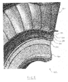
- FIG.5 is a view from upstream of an inventive stator arrangement 162 incorporating the vane segment 160 and the view is angled from the rotational axis 20.
- the stator arrangement 162 also includes a diaphragm 164 adapted to receive and be secured to the vane segments 160.
- the invention relates to a slot arrangement 112 circumferentially offset from the centre of the vane segment.
- the slot arrangement 112 is located adjacent to a free end 86, 88 of the vane segment 160, as opposed to either at the centre-span of the inner rail 90 or located in-between vane aerofoils 72 in contrast to the known arrangements described earlier.
- the temperature gradient induces circumferential bending stresses within the inner rail 90. These stresses are highest in the mid-span region of the inner rail 90 and decrease towards the free ends or the circumferential ends 86, 88 of the inner rail 90.
- the present invention relates to locating a slot arrangement 112 close to one of the free ends 86, 88, the stress at the slot arrangement 112 is significantly reduced because of the reduction in nominal stress in the inner rail 90 at this different location.
- the vane segment 160 has the inner rail 90 comprising the slot arrangement 112 which extends radially inwardly.
- the slot arrangement 112 comprises two fingers 116, 118 extending from the inner rail 90 and which define a slot 120 therebetween.
- the slot 120 is open at a radially inward end and has a centre-line 122.
- the slot 120 is located on the inner rail 90 a distance 124 to the centre-line 122 from one of the first or second circumferential ends 86, 88.
- the distance 124 can be between 5% and 30% of the length of the inner rail 90 and is preferentially approximately 10% of the length of the inner rail 90.
- One of the fingers 118 may be stepped away from the end face of the platform and/or inner rail 90.
- the distances quoted herein can instead be in relation to the circumferential length of the platform 64 and measured from the circumferential end 86, 88 of the platform 64. It is possible for some embodiments of the present invention for the slot arrangement 112 to be flush with the circumferential end of the inner rail and/or platform rather than stepped circumferentially inwardly from the end 86 as shown in FIG.4 .
- the aerofoils 66 have a leading edge 72 and an intersection 114 of the leading edge 72 and the inner platform 64 surface.
- the slot arrangement 112 is located on the inner rail 90 between one of the first or second circumferential ends 86, 88 and its respective first intersection 114 of the leading edge 72 and the inner platform 64.
- the centre-line 122 of the slot arrangement 112 is located between one of the circumferential ends 86, 88 and the circumferentially outer aerofoil 66 and in particular its leading edge 72.
- the extent of the distance between this intersection the circumferential end 88 is shown in FIG.4 as distance 126.
- the stator arrangement 162 includes an outer casing shown as 42 in FIG.1 , the vane segment 160 and the diaphragm 164.
- the vane segment 160 as described earlier comprises on the outer side 104 of the outer platform 62 the forward outer rail 106 and the rearward outer rail 108.
- the forward outer rail 106 and the rearward outer rail 108 secure the vane segment 160 to corresponding features of the outer casing 42 as is known in the art.
- the annular array of vane segments 160 form a rigid connection to the casing 42 and therefore securely hold the diaphragm 164 in its desired location relative to neighbouring rotating discs 36.
- the slot arrangement 112 engages into a groove 130 formed between two ring members 132, 134 that radially extend from the diaphragm 164. In other configurations other corresponding location features can be formed on the diaphragm to locate and secure the diaphragm with the vane segments.
- the groove 130 generally extends in a radial direction and is open at its radially outer limit.
- the groove 130 has a width in the axial direction and the slot arrangement 112 is sized to closely fit into the groove 130 and be slid circumferentially along the groove.
- the two ring members 132, 134 define corresponding holes 136.
- the vane segments 160 are located so that the slot centre-line 122 is aligned with the holes 136 and a dowel, pin or bolt 138 is inserted.
- the slot arrangement 112 prevents or resists relative movement between the vane segment 160 and the diaphragm 162 in the circumferential, radial and axial directions.
- each vane segment 160 in the annular array comprise seals (not shown) which are located in seal grooves 140 formed in the circumferential ends 66, 68 of the platforms 64, 62.
- the seals prevent hot gases escaping the passages 82 and ingressing to the radially internal spaces below the inner platform.
Landscapes
- Engineering & Computer Science (AREA)
- Mechanical Engineering (AREA)
- General Engineering & Computer Science (AREA)
- Turbine Rotor Nozzle Sealing (AREA)
- Structures Of Non-Positive Displacement Pumps (AREA)
Priority Applications (1)
| Application Number | Priority Date | Filing Date | Title |
|---|---|---|---|
| EP14191334.3A EP3015657A1 (de) | 2014-10-31 | 2014-10-31 | Gasturbinenleitschaufelsegment |
Applications Claiming Priority (1)
| Application Number | Priority Date | Filing Date | Title |
|---|---|---|---|
| EP14191334.3A EP3015657A1 (de) | 2014-10-31 | 2014-10-31 | Gasturbinenleitschaufelsegment |
Publications (1)
| Publication Number | Publication Date |
|---|---|
| EP3015657A1 true EP3015657A1 (de) | 2016-05-04 |
Family
ID=51868036
Family Applications (1)
| Application Number | Title | Priority Date | Filing Date |
|---|---|---|---|
| EP14191334.3A Withdrawn EP3015657A1 (de) | 2014-10-31 | 2014-10-31 | Gasturbinenleitschaufelsegment |
Country Status (1)
| Country | Link |
|---|---|
| EP (1) | EP3015657A1 (de) |
Cited By (2)
| Publication number | Priority date | Publication date | Assignee | Title |
|---|---|---|---|---|
| WO2022051759A1 (en) * | 2020-09-04 | 2022-03-10 | Siemens Energy Global GmbH & Co. KG | Guide vane in gas turbine engine |
| US11585242B2 (en) | 2020-03-25 | 2023-02-21 | MTU Aero Engines AG | Gas turbine component |
Citations (4)
| Publication number | Priority date | Publication date | Assignee | Title |
|---|---|---|---|---|
| GB2169038A (en) * | 1984-12-21 | 1986-07-02 | United Technologies Corp | Stator assembly for gas turbine engine |
| EP2383435A1 (de) * | 2010-04-29 | 2011-11-02 | Siemens Aktiengesellschaft | Hohle Innenführung einer Turbinenschaufel |
| US8376705B1 (en) * | 2011-09-09 | 2013-02-19 | Siemens Energy, Inc. | Turbine endwall with grooved recess cavity |
| EP2730745A1 (de) * | 2012-11-09 | 2014-05-14 | MTU Aero Engines GmbH | Schaufelanordnung für eine Turbomaschine |
-
2014
- 2014-10-31 EP EP14191334.3A patent/EP3015657A1/de not_active Withdrawn
Patent Citations (4)
| Publication number | Priority date | Publication date | Assignee | Title |
|---|---|---|---|---|
| GB2169038A (en) * | 1984-12-21 | 1986-07-02 | United Technologies Corp | Stator assembly for gas turbine engine |
| EP2383435A1 (de) * | 2010-04-29 | 2011-11-02 | Siemens Aktiengesellschaft | Hohle Innenführung einer Turbinenschaufel |
| US8376705B1 (en) * | 2011-09-09 | 2013-02-19 | Siemens Energy, Inc. | Turbine endwall with grooved recess cavity |
| EP2730745A1 (de) * | 2012-11-09 | 2014-05-14 | MTU Aero Engines GmbH | Schaufelanordnung für eine Turbomaschine |
Cited By (2)
| Publication number | Priority date | Publication date | Assignee | Title |
|---|---|---|---|---|
| US11585242B2 (en) | 2020-03-25 | 2023-02-21 | MTU Aero Engines AG | Gas turbine component |
| WO2022051759A1 (en) * | 2020-09-04 | 2022-03-10 | Siemens Energy Global GmbH & Co. KG | Guide vane in gas turbine engine |
Similar Documents
| Publication | Publication Date | Title |
|---|---|---|
| CN107435561B (zh) | 用于冷却涡轮叶片的尖端叶冠的密封导轨的系统 | |
| US11230935B2 (en) | Stator component cooling | |
| US9822647B2 (en) | High chord bucket with dual part span shrouds and curved dovetail | |
| US11015453B2 (en) | Engine component with non-diffusing section | |
| US20180245474A1 (en) | Arrangement for a gas turbine | |
| US8834096B2 (en) | Axial flow gas turbine | |
| US11015464B2 (en) | Conformal seal and vane bow wave cooling | |
| EP3441564A1 (de) | Turbomaschinenkomponente welche eine platform mit eindrückung beinhaltet | |
| US11085308B2 (en) | Compressor aerofoil | |
| US10738701B2 (en) | Conformal seal bow wave cooling | |
| EP3015657A1 (de) | Gasturbinenleitschaufelsegment | |
| US10927678B2 (en) | Turbine vane having improved flexibility | |
| US10161266B2 (en) | Nozzle and nozzle assembly for gas turbine engine | |
| US20200063586A1 (en) | Spline Seal with Cooling Features for Turbine Engines | |
| US20200355086A1 (en) | Rim seal arrangement | |
| US20200217214A1 (en) | Rim seal | |
| WO2018128609A1 (en) | Seal assembly between a hot gas path and a rotor disc cavity | |
| US10738638B2 (en) | Rotor blade with wheel space swirlers and method for forming a rotor blade with wheel space swirlers | |
| US11566536B1 (en) | Turbine HGP component with stress relieving cooling circuit | |
| EP3839218B1 (de) | Verbesserte rotorschaufeldichtungsstrukturen | |
| US11041391B2 (en) | Conformal seal and vane bow wave cooling | |
| US9719355B2 (en) | Rotary machine blade having an asymmetric part-span shroud and method of making same | |
| US20220090504A1 (en) | Rotor blade for a gas turbine engine having a metallic structural member and a composite fairing | |
| US20180172027A1 (en) | Gas turbine engine |
Legal Events
| Date | Code | Title | Description |
|---|---|---|---|
| PUAI | Public reference made under article 153(3) epc to a published international application that has entered the european phase |
Free format text: ORIGINAL CODE: 0009012 |
|
| AK | Designated contracting states |
Kind code of ref document: A1 Designated state(s): AL AT BE BG CH CY CZ DE DK EE ES FI FR GB GR HR HU IE IS IT LI LT LU LV MC MK MT NL NO PL PT RO RS SE SI SK SM TR |
|
| AX | Request for extension of the european patent |
Extension state: BA ME |
|
| STAA | Information on the status of an ep patent application or granted ep patent |
Free format text: STATUS: THE APPLICATION HAS BEEN PUBLISHED |
|
| STAA | Information on the status of an ep patent application or granted ep patent |
Free format text: STATUS: THE APPLICATION IS DEEMED TO BE WITHDRAWN |
|
| 18D | Application deemed to be withdrawn |
Effective date: 20161105 |