EP3015564A1 - Method for manufacturing laminated rings - Google Patents
Method for manufacturing laminated rings Download PDFInfo
- Publication number
- EP3015564A1 EP3015564A1 EP14817076.4A EP14817076A EP3015564A1 EP 3015564 A1 EP3015564 A1 EP 3015564A1 EP 14817076 A EP14817076 A EP 14817076A EP 3015564 A1 EP3015564 A1 EP 3015564A1
- Authority
- EP
- European Patent Office
- Prior art keywords
- rings
- ring
- pipe
- layered
- layered ring
- Prior art date
- Legal status (The legal status is an assumption and is not a legal conclusion. Google has not performed a legal analysis and makes no representation as to the accuracy of the status listed.)
- Granted
Links
- 238000004519 manufacturing process Methods 0.000 title claims abstract description 33
- 238000000034 method Methods 0.000 title abstract description 24
- 238000005121 nitriding Methods 0.000 claims abstract description 25
- 238000005498 polishing Methods 0.000 claims abstract description 16
- 238000005520 cutting process Methods 0.000 claims abstract description 13
- 229910052751 metal Inorganic materials 0.000 claims description 27
- 239000002184 metal Substances 0.000 claims description 23
- 238000003466 welding Methods 0.000 claims description 22
- 229910000831 Steel Inorganic materials 0.000 claims description 13
- 239000010959 steel Substances 0.000 claims description 13
- 238000010438 heat treatment Methods 0.000 description 34
- 239000010410 layer Substances 0.000 description 27
- 239000000203 mixture Substances 0.000 description 9
- 239000011229 interlayer Substances 0.000 description 7
- 230000001590 oxidative effect Effects 0.000 description 7
- 239000000463 material Substances 0.000 description 5
- 230000032683 aging Effects 0.000 description 4
- 230000005540 biological transmission Effects 0.000 description 4
- 230000000694 effects Effects 0.000 description 3
- 238000007517 polishing process Methods 0.000 description 3
- 238000005096 rolling process Methods 0.000 description 3
- 238000009826 distribution Methods 0.000 description 2
- 230000008030 elimination Effects 0.000 description 2
- 238000003379 elimination reaction Methods 0.000 description 2
- 238000007689 inspection Methods 0.000 description 2
- 238000005406 washing Methods 0.000 description 2
- 229910001240 Maraging steel Inorganic materials 0.000 description 1
- 238000001816 cooling Methods 0.000 description 1
- 230000002542 deteriorative effect Effects 0.000 description 1
- 238000005259 measurement Methods 0.000 description 1
- 150000004767 nitrides Chemical class 0.000 description 1
- 238000002360 preparation method Methods 0.000 description 1
- 239000002994 raw material Substances 0.000 description 1
- 230000003252 repetitive effect Effects 0.000 description 1
- 229910001220 stainless steel Inorganic materials 0.000 description 1
- 239000010935 stainless steel Substances 0.000 description 1
Images





Classifications
-
- F—MECHANICAL ENGINEERING; LIGHTING; HEATING; WEAPONS; BLASTING
- F16—ENGINEERING ELEMENTS AND UNITS; GENERAL MEASURES FOR PRODUCING AND MAINTAINING EFFECTIVE FUNCTIONING OF MACHINES OR INSTALLATIONS; THERMAL INSULATION IN GENERAL
- F16G—BELTS, CABLES, OR ROPES, PREDOMINANTLY USED FOR DRIVING PURPOSES; CHAINS; FITTINGS PREDOMINANTLY USED THEREFOR
- F16G5/00—V-belts, i.e. belts of tapered cross-section
- F16G5/16—V-belts, i.e. belts of tapered cross-section consisting of several parts
-
- B—PERFORMING OPERATIONS; TRANSPORTING
- B21—MECHANICAL METAL-WORKING WITHOUT ESSENTIALLY REMOVING MATERIAL; PUNCHING METAL
- B21D—WORKING OR PROCESSING OF SHEET METAL OR METAL TUBES, RODS OR PROFILES WITHOUT ESSENTIALLY REMOVING MATERIAL; PUNCHING METAL
- B21D53/00—Making other particular articles
- B21D53/14—Making other particular articles belts, e.g. machine-gun belts
-
- B—PERFORMING OPERATIONS; TRANSPORTING
- B21—MECHANICAL METAL-WORKING WITHOUT ESSENTIALLY REMOVING MATERIAL; PUNCHING METAL
- B21D—WORKING OR PROCESSING OF SHEET METAL OR METAL TUBES, RODS OR PROFILES WITHOUT ESSENTIALLY REMOVING MATERIAL; PUNCHING METAL
- B21D53/00—Making other particular articles
- B21D53/16—Making other particular articles rings, e.g. barrel hoops
-
- B—PERFORMING OPERATIONS; TRANSPORTING
- B23—MACHINE TOOLS; METAL-WORKING NOT OTHERWISE PROVIDED FOR
- B23P—METAL-WORKING NOT OTHERWISE PROVIDED FOR; COMBINED OPERATIONS; UNIVERSAL MACHINE TOOLS
- B23P15/00—Making specific metal objects by operations not covered by a single other subclass or a group in this subclass
-
- C—CHEMISTRY; METALLURGY
- C21—METALLURGY OF IRON
- C21D—MODIFYING THE PHYSICAL STRUCTURE OF FERROUS METALS; GENERAL DEVICES FOR HEAT TREATMENT OF FERROUS OR NON-FERROUS METALS OR ALLOYS; MAKING METAL MALLEABLE, e.g. BY DECARBURISATION OR TEMPERING
- C21D9/00—Heat treatment, e.g. annealing, hardening, quenching or tempering, adapted for particular articles; Furnaces therefor
- C21D9/40—Heat treatment, e.g. annealing, hardening, quenching or tempering, adapted for particular articles; Furnaces therefor for rings; for bearing races
-
- C—CHEMISTRY; METALLURGY
- C21—METALLURGY OF IRON
- C21D—MODIFYING THE PHYSICAL STRUCTURE OF FERROUS METALS; GENERAL DEVICES FOR HEAT TREATMENT OF FERROUS OR NON-FERROUS METALS OR ALLOYS; MAKING METAL MALLEABLE, e.g. BY DECARBURISATION OR TEMPERING
- C21D9/00—Heat treatment, e.g. annealing, hardening, quenching or tempering, adapted for particular articles; Furnaces therefor
- C21D9/50—Heat treatment, e.g. annealing, hardening, quenching or tempering, adapted for particular articles; Furnaces therefor for welded joints
-
- C—CHEMISTRY; METALLURGY
- C23—COATING METALLIC MATERIAL; COATING MATERIAL WITH METALLIC MATERIAL; CHEMICAL SURFACE TREATMENT; DIFFUSION TREATMENT OF METALLIC MATERIAL; COATING BY VACUUM EVAPORATION, BY SPUTTERING, BY ION IMPLANTATION OR BY CHEMICAL VAPOUR DEPOSITION, IN GENERAL; INHIBITING CORROSION OF METALLIC MATERIAL OR INCRUSTATION IN GENERAL
- C23C—COATING METALLIC MATERIAL; COATING MATERIAL WITH METALLIC MATERIAL; SURFACE TREATMENT OF METALLIC MATERIAL BY DIFFUSION INTO THE SURFACE, BY CHEMICAL CONVERSION OR SUBSTITUTION; COATING BY VACUUM EVAPORATION, BY SPUTTERING, BY ION IMPLANTATION OR BY CHEMICAL VAPOUR DEPOSITION, IN GENERAL
- C23C8/00—Solid state diffusion of only non-metal elements into metallic material surfaces; Chemical surface treatment of metallic material by reaction of the surface with a reactive gas, leaving reaction products of surface material in the coating, e.g. conversion coatings, passivation of metals
- C23C8/02—Pretreatment of the material to be coated
-
- C—CHEMISTRY; METALLURGY
- C23—COATING METALLIC MATERIAL; COATING MATERIAL WITH METALLIC MATERIAL; CHEMICAL SURFACE TREATMENT; DIFFUSION TREATMENT OF METALLIC MATERIAL; COATING BY VACUUM EVAPORATION, BY SPUTTERING, BY ION IMPLANTATION OR BY CHEMICAL VAPOUR DEPOSITION, IN GENERAL; INHIBITING CORROSION OF METALLIC MATERIAL OR INCRUSTATION IN GENERAL
- C23C—COATING METALLIC MATERIAL; COATING MATERIAL WITH METALLIC MATERIAL; SURFACE TREATMENT OF METALLIC MATERIAL BY DIFFUSION INTO THE SURFACE, BY CHEMICAL CONVERSION OR SUBSTITUTION; COATING BY VACUUM EVAPORATION, BY SPUTTERING, BY ION IMPLANTATION OR BY CHEMICAL VAPOUR DEPOSITION, IN GENERAL
- C23C8/00—Solid state diffusion of only non-metal elements into metallic material surfaces; Chemical surface treatment of metallic material by reaction of the surface with a reactive gas, leaving reaction products of surface material in the coating, e.g. conversion coatings, passivation of metals
- C23C8/06—Solid state diffusion of only non-metal elements into metallic material surfaces; Chemical surface treatment of metallic material by reaction of the surface with a reactive gas, leaving reaction products of surface material in the coating, e.g. conversion coatings, passivation of metals using gases
- C23C8/08—Solid state diffusion of only non-metal elements into metallic material surfaces; Chemical surface treatment of metallic material by reaction of the surface with a reactive gas, leaving reaction products of surface material in the coating, e.g. conversion coatings, passivation of metals using gases only one element being applied
- C23C8/10—Oxidising
-
- C—CHEMISTRY; METALLURGY
- C23—COATING METALLIC MATERIAL; COATING MATERIAL WITH METALLIC MATERIAL; CHEMICAL SURFACE TREATMENT; DIFFUSION TREATMENT OF METALLIC MATERIAL; COATING BY VACUUM EVAPORATION, BY SPUTTERING, BY ION IMPLANTATION OR BY CHEMICAL VAPOUR DEPOSITION, IN GENERAL; INHIBITING CORROSION OF METALLIC MATERIAL OR INCRUSTATION IN GENERAL
- C23C—COATING METALLIC MATERIAL; COATING MATERIAL WITH METALLIC MATERIAL; SURFACE TREATMENT OF METALLIC MATERIAL BY DIFFUSION INTO THE SURFACE, BY CHEMICAL CONVERSION OR SUBSTITUTION; COATING BY VACUUM EVAPORATION, BY SPUTTERING, BY ION IMPLANTATION OR BY CHEMICAL VAPOUR DEPOSITION, IN GENERAL
- C23C8/00—Solid state diffusion of only non-metal elements into metallic material surfaces; Chemical surface treatment of metallic material by reaction of the surface with a reactive gas, leaving reaction products of surface material in the coating, e.g. conversion coatings, passivation of metals
- C23C8/06—Solid state diffusion of only non-metal elements into metallic material surfaces; Chemical surface treatment of metallic material by reaction of the surface with a reactive gas, leaving reaction products of surface material in the coating, e.g. conversion coatings, passivation of metals using gases
- C23C8/08—Solid state diffusion of only non-metal elements into metallic material surfaces; Chemical surface treatment of metallic material by reaction of the surface with a reactive gas, leaving reaction products of surface material in the coating, e.g. conversion coatings, passivation of metals using gases only one element being applied
- C23C8/24—Nitriding
- C23C8/26—Nitriding of ferrous surfaces
-
- C—CHEMISTRY; METALLURGY
- C23—COATING METALLIC MATERIAL; COATING MATERIAL WITH METALLIC MATERIAL; CHEMICAL SURFACE TREATMENT; DIFFUSION TREATMENT OF METALLIC MATERIAL; COATING BY VACUUM EVAPORATION, BY SPUTTERING, BY ION IMPLANTATION OR BY CHEMICAL VAPOUR DEPOSITION, IN GENERAL; INHIBITING CORROSION OF METALLIC MATERIAL OR INCRUSTATION IN GENERAL
- C23C—COATING METALLIC MATERIAL; COATING MATERIAL WITH METALLIC MATERIAL; SURFACE TREATMENT OF METALLIC MATERIAL BY DIFFUSION INTO THE SURFACE, BY CHEMICAL CONVERSION OR SUBSTITUTION; COATING BY VACUUM EVAPORATION, BY SPUTTERING, BY ION IMPLANTATION OR BY CHEMICAL VAPOUR DEPOSITION, IN GENERAL
- C23C8/00—Solid state diffusion of only non-metal elements into metallic material surfaces; Chemical surface treatment of metallic material by reaction of the surface with a reactive gas, leaving reaction products of surface material in the coating, e.g. conversion coatings, passivation of metals
- C23C8/06—Solid state diffusion of only non-metal elements into metallic material surfaces; Chemical surface treatment of metallic material by reaction of the surface with a reactive gas, leaving reaction products of surface material in the coating, e.g. conversion coatings, passivation of metals using gases
- C23C8/34—Solid state diffusion of only non-metal elements into metallic material surfaces; Chemical surface treatment of metallic material by reaction of the surface with a reactive gas, leaving reaction products of surface material in the coating, e.g. conversion coatings, passivation of metals using gases more than one element being applied in more than one step
-
- C—CHEMISTRY; METALLURGY
- C21—METALLURGY OF IRON
- C21D—MODIFYING THE PHYSICAL STRUCTURE OF FERROUS METALS; GENERAL DEVICES FOR HEAT TREATMENT OF FERROUS OR NON-FERROUS METALS OR ALLOYS; MAKING METAL MALLEABLE, e.g. BY DECARBURISATION OR TEMPERING
- C21D1/00—General methods or devices for heat treatment, e.g. annealing, hardening, quenching or tempering
- C21D1/06—Surface hardening
-
- C—CHEMISTRY; METALLURGY
- C21—METALLURGY OF IRON
- C21D—MODIFYING THE PHYSICAL STRUCTURE OF FERROUS METALS; GENERAL DEVICES FOR HEAT TREATMENT OF FERROUS OR NON-FERROUS METALS OR ALLOYS; MAKING METAL MALLEABLE, e.g. BY DECARBURISATION OR TEMPERING
- C21D2261/00—Machining or cutting being involved
-
- Y—GENERAL TAGGING OF NEW TECHNOLOGICAL DEVELOPMENTS; GENERAL TAGGING OF CROSS-SECTIONAL TECHNOLOGIES SPANNING OVER SEVERAL SECTIONS OF THE IPC; TECHNICAL SUBJECTS COVERED BY FORMER USPC CROSS-REFERENCE ART COLLECTIONS [XRACs] AND DIGESTS
- Y10—TECHNICAL SUBJECTS COVERED BY FORMER USPC
- Y10T—TECHNICAL SUBJECTS COVERED BY FORMER US CLASSIFICATION
- Y10T29/00—Metal working
- Y10T29/49—Method of mechanical manufacture
- Y10T29/49789—Obtaining plural product pieces from unitary workpiece
- Y10T29/49798—Dividing sequentially from leading end, e.g., by cutting or breaking
-
- Y—GENERAL TAGGING OF NEW TECHNOLOGICAL DEVELOPMENTS; GENERAL TAGGING OF CROSS-SECTIONAL TECHNOLOGIES SPANNING OVER SEVERAL SECTIONS OF THE IPC; TECHNICAL SUBJECTS COVERED BY FORMER USPC CROSS-REFERENCE ART COLLECTIONS [XRACs] AND DIGESTS
- Y10—TECHNICAL SUBJECTS COVERED BY FORMER USPC
- Y10T—TECHNICAL SUBJECTS COVERED BY FORMER US CLASSIFICATION
- Y10T29/00—Metal working
- Y10T29/49—Method of mechanical manufacture
- Y10T29/49813—Shaping mating parts for reassembly in different positions
Definitions
- the present invention relates to a manufacturing method for a multi-layered ring used for a transmission belt of a belt-type continuously variable transmission for a vehicle.
- a belt-type CVT Continuous Variable Transmission
- Fig. 13 is a perspective view showing an endless metal belt 10 used for the CVT.
- Fig. 14 is a partial perspective view showing a part of the endless metal belt 10 in which the endless metal belt 10 is partially disassembled.
- the endless metal belt 10 is obtained by concatenating a plurality of metal elements 11 each of which is a plate-like element in the thickness direction and forming the concatenated metal elements 11 into a ring shape as a whole.
- multi-layered rings 12 are inserted into the metal elements 11 from both sides thereof in the width direction.
- Each of the multi-layered rings 12 is formed by stacking six to twelve endless metal rings 13 having slightly different circumferential lengths on each other. (In Fig. 13 , only three endless metal rings are layered because the structure is simplified for clarifying the illustration.)
- the inner most endless metal ring 13 is referred to as a "first ring” and the endless metal ring 13 layered on the outer side of the first ring is referred to as a "second ring”.
- other metal rings 13 are named in such a manner that their numbers increase from the inner side toward the outer side of the rings.
- the circumferential length of a ring is slightly longer than that of a ring disposed immediately inside that ring. Therefore, when the outer-side ring is layered on the inner-side ring, these rings are substantially in intimate contact with each other throughout the entire circumference.
- each endless metal ring 13 In manufacture the multi-layered ring 12, it is necessary to control the circumferential length of each endless metal ring 13 in an extremely strict manner so that the clearance between an inner ring and the ring disposed immediately outside that ring (hereinafter called an "inter-layer clearance") is smaller than a prescribed tolerance.
- the inter-layer clearance between the k-th ring and the (k+1)-th ring is larger than the prescribed tolerance, it causes these rings to be rubbed against each other and thus eventually to be torn.
- the outer circumferential length of the k-th ring is larger than the inner circumferential length of the (k+1)-th ring, they cannot be layered on each other as a matter of course.
- the circumferential lengths of rings are adjusted so that these rings exhibit circumferential lengths respectively predetermined for them. That is, each ring is stretched to its determined circumferential length by applying a tension (tensile force).
- a tension tensile force
- there are predetermined target values for the circumferential lengths for the rings i.e., the ring that will become the first ring, the ring that will become the second ring, and so on.
- various technical ideas have been proposed to adjust the circumferential length with a very high accuracy.
- Patent Literature 2 Japanese Unexamined Patent Application Publications No. 2011-185300 (Patent Literature 2) and No. 2013-52432 (Patent Literature 3), which were filed by the applicant of the present application, disclose circumferential length adjustment devices and circumferential length adjustment processes in which considerable contrivances are made.
- a multi-layered ring i.e., each of the endless metal belts constituting the multi-layered ring, needs to exhibit a high strength as a matter of course. Therefore, after the circumferential length adjustment, a heat treatment(s) such as aging, oxidizing, and nitriding is performed in order to improve, for example, the hardness and/or the wear resistance of the multi-layered ring (Patent Literatures 4 and 5).
- An object of the present invention is to further improve the production efficiency of the multi-layered ring.
- a manufacturing method for a multi-layered ring according to the present invention is a manufacturing method for a multi-layered ring, the multi-layered ring being formed by layering a plurality of endless metal rings having slightly different circumferential lengths on one another, the manufacturing method including: a welding step of welding ends of a steel plate together and thereby forming a cylindrical pipe; a ring cutting-out step of cutting the pipe at a predetermined width in a direction perpendicular to a central axis of the pipe and thereby cutting out a plurality of rings; a polishing step of polishing the rings; a circumferential length adjustment step of adjusting the plurality of rings so that they exhibit circumferential lengths respectively predetermined for them; a nitriding step of nitriding the plurality of rings; and an assembling step of assembling in order to layer the plurality of rings into a multi-layered ring, in which the assembling step is performed so that rings that were parts originally adjacent to each other in a state of the pipe become layers that
- each of the plurality of rings is polished one by one so that an order in which the plurality of rings are cut out in the cutting-out step can be kept track of.
- the nitriding step is preferably performed in a state where the plurality of rings are set in a jig in such a manner that rings that were parts originally adjacent to each other in the state of the pipe are disposed adjacent to each other in the jig.
- the circumferential length of each ring is preferably adjusted so that rings that were parts originally adjacent to each other in the state of the pipe become layers that are adjacent to each other in the multi-layered ring.
- a manufacturing method for a multi-layered ring according to the present invention is a manufacturing method for a multi-layered ring, the multi-layered ring being formed by layering a plurality of endless metal rings having slightly different circumferential lengths on one another, the manufacturing method including: a welding step of welding ends of a steel plate together and thereby forming a cylindrical pipe; a ring cutting-out step of cutting the pipe at a predetermined width in a direction perpendicular to a central axis of the pipe and thereby cutting out a plurality of rings; a polishing step of polishing the rings; a circumferential length adjustment step of adjusting the plurality of rings so that they exhibit circumferential lengths respectively predetermined for them; a nitriding step of nitriding the plurality of rings; and an assembling step of assembling in order to layer the plurality of rings into a multi-layered ring, in which in the assembling step, a predetermined number of rings among the plurality of rings cut out from a single pipe are
- a manufacturing method for a multi-layered ring according to the present invention is a manufacturing method for a multi-layered ring, the multi-layered ring being formed by layering a plurality of endless metal rings having slightly different circumferential lengths on one another, the manufacturing method including: a welding step of welding ends of a steel plate together and thereby forming a cylindrical pipe; a ring cutting-out step of cutting the pipe at a predetermined width in a direction perpendicular to a central axis of the pipe and thereby cutting out a plurality of rings; a polishing step of polishing the rings; a circumferential length adjustment step of adjusting the plurality of rings so that they exhibit circumferential lengths respectively predetermined for them; a nitriding step of nitriding the plurality of rings; and an assembling step of assembling in order to layer the plurality of rings into a multi-layered ring, in which in the assembling step, a predetermined number of rings among the plurality of rings cut out from a part of the
- a plurality of rings are assembled into a multi-layered ring so that rings that were parts originally adjacent to each other in the state of the pipe become layers that are adjacent to each other in the multi-layered ring.
- rings that are adjacent to each other in the pipe have substantially the same compositions, plate thicknesses, and welding quality as each other. Therefore, it can be expected that for layers that are adjacent to each other in a multi-layered ring, even if they elongate to some degree at the stage of the heat treatment (nitriding step), their elongations have substantially the same tendencies. This leads to the elimination of the task of the ring length measurement, the sorting out, and the selection after the heat treatment, and consequently reduces the troublesome processes and the cost and improves the production efficiency.
- Figs. 1 to 3 show a flowchart of a multi-layered ring manufacturing method.
- a steel plate 21 is cut out from a roll 20 (ST101). After the cut-out steel plate 21 is bent into a cylindrical shape (ST102), its ends are welded together and a pipe 22 is thereby created (ST103).
- Fig. 4 shows a state where the steel plate 21 cut out from the roll 20 is formed into the pipe 22. Note that the material for the roll 20 is steel such as maraging steel and stainless steel.
- a first solution heat treatment for eliminating the effect of the heat in the welding process is performed (ST104).
- 12 pipes 22 are processed in a batch (see Fig. 5 ).
- each pipe 22 is cut in a direction perpendicular to the central axis of the pipe 22 and rings 23 are thereby cut out from the pipe 22 (ST105).
- This step is one of the important features of the present invention and hence will be explained hereinafter in detail.
- one complete multi-layered ring is formed by layering nine layers of rings 23 on one another. Further, assume that 18 rings 23 are cut out from a single pipe 22 in the ring cutting-out step. That is, a plurality of rings 23 corresponding to two of multi-layered rings are cut out from a single pipe 22.
- Figs. 6 , 7 and 8 show states where 18 rings 23 are cut out from a single pipe 22.
- Fig. 6(a) shows a pipe 22 before rings 23 are cut out from it. Assume that numbers are assigned to sections of this pipe 22 at intervals corresponding to the width of the rings 23 from the right end of the pipe 22. Since 18 rings 23 are cut out from the single pipe 22, numbers 1 to 18 are assigned at the predetermined width intervals from the right end of the pipe 22. Then, as shown in Fig. 6(b) , the pipe 22 is cut in round slices from the right end. It should be noted that the order of the rings 23 should be kept even after they are cut out. That is, the rings 23 should be managed so that the mutual positional relation in the order of the rings 23 is not disrupted. For example, as shown in Fig.
- the rings 23 may be cut out from the right end of the pipe 22 in the numerical order and the cut-out rings 23 may be conveyed by a belt conveyer 90 in the order in which they have been cut out. By doing so, the order of the rings 23 can be kept without being disrupted (see Fig. 8 ).
- the rings 23 may be put in a belt conveyer, may be put in a turntable, or may be put in a tray in an orderly manner so that their order is kept.
- the cut-out rings are polished (ST106). Burrs are removed and corners are rounded (chamfering). It is also important to keep the order of the rings 23 so that it is not disrupted in this polishing process.
- each of the rings may be polished one by one by using a brush.
- removal of burrs and rounding (chamfering) for the rings may be performed one by one by laser for each ring.
- each of the rings may be polished one by one by using a barrel.
- each of the rings 23 is rolled so as to have a predetermined thickness.
- each of the rings 23 is sandwiched between a pair of reduction rollers in the thickness direction and a pressure is applied thereto.
- the circumferential lengths of the rolled (i.e., flattened) rings 23 are adjusted so that they exhibit circumferential lengths respectively predetermined for them (ST111). That is, the rings 23 are stretched and adjusted by applying a tension (tensile force) so that they have determined circumferential lengths.
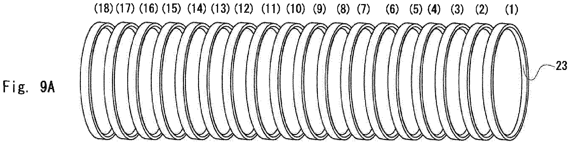
- Fig. 9 shows rings that will be subjected to a circumferential length adjustment process, in which the rings are arranged so that their original order is kept. Throughout the preceding steps, the rings have been managed so that their mutual relation in the order is not disrupted. Therefore, it can be understood that the rings 23 can be arranged so that their original order is kept as shown in Fig. 9(a) .
- 18 rings 23 are cut out from a single pipe 22 and two of multi-layered rings are created. Therefore, one of the two of multi-layered rings is referred to as a "first multi-layered ring 12A" and the other multi layered ring is referred to as a "second multi-layered ring 12B".
- first ring the innermost ring in a multi-layered ring
- second ring the ring layered on the outer side of the first ring
- other rings are named in such a manner that their numbers increase from the inner side to the outer side of the rings.
- first multi-layered ring 12A should be formed so that the first ring (1) becomes the first ring of the first multi-layered ring 12A (see Fig. 9(b) ).
- the second ring (2) becomes the second ring of the first multi-layered ring 12A.
- the third ring (3) becomes the third ring of the first multi-layered ring 12A.
- the remaining rings are assembled in a similar manner and the ninth ring (9) becomes the ninth ring of the first multi-layered ring 12A.
- the first ring (1) is adjusted so as to have the circumferential length of the first ring of the multi-layered ring.
- the second ring (2) is adjusted so as to have the circumferential length of the second ring of the multi-layered ring, and so on.
- the second multi-layered ring 12B is formed in a manner similar to the manner in which first multi-layered ring 12A is formed. That is, the 10th ring (10) becomes the first ring of the second multi-layered ring 12B.
- the 11th ring (11) becomes the second ring of the second multi-layered ring 12B.
- the 12th ring (12) becomes the third ring of the second multi-layered ring 12B.
- the remaining rings are assembled in a similar manner and the 18th ring (18) becomes the ninth ring of the second multi-layered ring 12B.
- Fig. 9(b) schematically shows a state after circumferential length adjustments are performed for the rings 23 so that they have target circumferential lengths for the respective layers.
- a preparation for the heat treatment is made. That is, to convey the rings, for which the circumferential length adjustment (ST111) has been performed, to a heat treatment furnace, the rings 23 are set (i.e., put) in a ring loading jig 80.
- Fig. 10 shows a state where the rings 23 are set in the ring loading jig 80.
- rings that become layers adjacent to each other in the multi-layered ring should be subjected to the heat treatment under roughly the same condition.
- rings that become layers adjacent to each other in the multi-layered ring should undergo the heat treatment while keeping their positions as close to each other as possible.
- a set of rings, which will be assembled into one multi-layered ring in the future, are set in the ring loading jig.
- Fig. 9 shows an example of the ring loading jig.
- the ring loading jig 80 includes a bottom plate 81 and a post 82 disposed in the bottom plate 81 in a standing position, and the post 82 includes a plurality of flanges (not shown).
- the ring loading jig 80 is configured so that the rings 23 are hooked by the flanges. In this way, a set of the rings 23 (i.e., nine rings 23) can be set in one ring loading jig 80.
- the rings 23 are preferably set in the ring loading jig 80 so that rings that become layers adjacent to each other in the multi-layered ring are disposed adjacent to each other.
- the first ring i.e., the first ring of the multi-layered ring
- the second ring i.e., the second ring of the multi-layered ring
- the third ring i.e., the third ring of the multi-layered ring
- the remaining rings are placed in a similar fashion, explanations thereof are omitted.
- the ring loading jig 80 in which the rings 23 are set, is placed on a conveyer (not shown) (ST114) and sent to the heat treatment furnace.
- the heat treatment itself is a well-known process, in which aging (ST115), oxidizing (ST116), and nitriding (ST117) are performed for the rings 23.
- the rings are heated to a predetermined temperature, left at the raised temperature for a sufficient time period, and then cooled.
- the rings are subjected to an oxidizing process at a predetermined oxidizing process temperature in an oxidizing atmosphere, and an oxide layer is thereby generated.
- the rings are subjected to a nitriding process at a predetermined nitriding process temperature in a nitriding atmosphere, and a nitride layer is thereby generated.
- the heat treatment furnace incudes a plurality of processing chambers partitioned by doors, and the ring loading jig 80 is successively passed through each of the processing chambers by the conveyer.
- the conveyer Upon completing the heat treatment (ST115 to ST117), the conveyer is carried out from the heat treatment furnace (ST118).
- the rings 23, for which the heat treatment has been performed are subjected to a predetermined inspection(s) (e.g., a surface inspection ST119) and then assembled into a multi-layered ring 12.
- a predetermined inspection(s) e.g., a surface inspection ST119
- the nine rings 23 set in the one ring loading jig 80 may be assembled into the multi-layered ring 12 without adding or removing any rings.
- the multi-layered ring 12 produced in the above-described manner may be shipped.
- the above-described first exemplary embodiment provides the following advantageous effects.
- One of the features of the first exemplary embodiment is that rings that are adjacent to each other in the pipe 22 become layers that are adjacent to each other even when they are assembled into the multi-layered ring 12.
- the roll 20 which is the raw material, has some variations in plate thickness and material composition according to the place within the roll 20. (For example, regarding the plate thickness, it fluctuates by about 3 ⁇ m to 4 ⁇ m according to the place.) Further, the steel plate is bent and then both ends of it are welded together to create the pipe 22 as described above, and it is thus unavoidable that the welding quality varies according to the place within the roll 20.
- the variations in the amounts of the elongations of the rings could be about several hundred ⁇ m on either of the positive and negative sides.
- rings that are adjacent to each other in the pipe 22 become layers that are adjacent to each other even when they are assembled into the multi-layered ring 12. It can be expected that rings that are adjacent to each other in the pipe 22 have substantially the same compositions, plate thicknesses, and welding quality. Further, in this exemplary embodiment, rings that become layers adjacent to each other in the multi-layered ring 12 are subjected to the heat treatment under roughly the same condition. Therefore, it can be expected that, for layers that are adjacent to each other in a multi-layered ring 12, even if they elongate to some degree in the heat treatment, their elongations have substantially the same tendencies.
- the nine rings 23 can be assembled into the nine layers constituting the multi-layered ring 12 exactly according to the order of the rings 23 at the time when they are set in the ring loading jig 80. This leads to the elimination of the tasks of measuring the length of the rings 23, sorting out of the rings, and selecting the rings after the heat treatment, and consequently reduces the troublesome processes and the cost and improves the production efficiency.
- the order of rings can be changed within a set of rings (e.g., nine rings) that will form one multi-layered ring.
- a first multi-layered ring is obtained from the right half of the pipe 22 and a second multi-layered ring is obtained from the left half of the pipe 22. (In Fig. 11 , due to the width of the paper, the illustration for the second multi-layered ring is omitted.) That is, the first to ninth rings constituting the first multi-layered ring are cut out from the right half of the pipe 22.
- the order of the nine rings cut out from the right half of the pipe 22 does not need to be managed. That is, after the nine rings 23 are cut out from the right half of the pipe 22, they may be processed in a batch.
- the nine rings 23 may be barrel-polished together.
- One of the nine rings is used as the first ring and one of the remaining rings is used as the second ring. Further, one of the remaining rings used as the third rings, and so on (the explanation of the remaining is omitted).
- the first ring (1) and the ninth ring (9), for example, could become layers adjacent to each other.
- Fig. 11(c) shows an example where the first ring (1) becomes the fourth ring of the multi-layered ring and the ninth ring becomes the fifth ring of the multi-layered ring.
- the numbers are arbitrarily assigned.
- the 10th to 18th rings may be shuffled. Since the reason for this is similar to that for first multi-layered ring, repetitive explanations are omitted.
- 18 rings 23 may be barrel-polished together.
- the first multi-layered ring is created by using half of 18 rings and the second multi-layered ring is created by using the other half.
- the first ring (1) and the 18th ring (18), for example, could become layers adjacent to each other.
- the compositions, the plate thicknesses, and the welding quality do not widely vary from one another, the variations in the inter-layer clearance is very small even when the rings are elongated to some degree due to the heat treatment.
- each of cut-out rings is processed in turn in the subsequent processes so that the order of the cut-out rings is not changed is shown.
- the simplest way is to put the cut-out rings in an assembly-line system in the order in which they have been cut out so that their order is not changed.
- each of the cut-out rings may be marked so that their order can be recognized. By doing so, even when the rings are subjected to the polishing process in a batch, for example, they can be rearranged according to the original order prior to the circumferential length adjustment process and the heat treatment.
- a plurality of rings may be processed in parallel in a plurality of lanes, provided that the order of the rings can be managed. That is, various contrivances may be made for the actual production processes.
Landscapes
- Chemical & Material Sciences (AREA)
- Engineering & Computer Science (AREA)
- Mechanical Engineering (AREA)
- Organic Chemistry (AREA)
- Materials Engineering (AREA)
- Metallurgy (AREA)
- Chemical Kinetics & Catalysis (AREA)
- General Engineering & Computer Science (AREA)
- Physics & Mathematics (AREA)
- Thermal Sciences (AREA)
- Crystallography & Structural Chemistry (AREA)
- Heat Treatment Of Articles (AREA)
- Grinding And Polishing Of Tertiary Curved Surfaces And Surfaces With Complex Shapes (AREA)
- Solid-Phase Diffusion Into Metallic Material Surfaces (AREA)
Abstract
Description
- The present invention relates to a manufacturing method for a multi-layered ring used for a transmission belt of a belt-type continuously variable transmission for a vehicle.
- There is a belt-type CVT (Continuously Variable Transmission) capable of changing the gear ratio of a transmission of a vehicle in a stepless manner according to the traveling state of the vehicle (for example, Patent Literature 1).
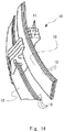
Fig. 13 is a perspective view showing anendless metal belt 10 used for the CVT.Fig. 14 is a partial perspective view showing a part of theendless metal belt 10 in which theendless metal belt 10 is partially disassembled. - The
endless metal belt 10 is obtained by concatenating a plurality ofmetal elements 11 each of which is a plate-like element in the thickness direction and forming the concatenatedmetal elements 11 into a ring shape as a whole. To support the plurality ofmetal elements 11 in the ring shape,multi-layered rings 12 are inserted into themetal elements 11 from both sides thereof in the width direction. - Each of the
multi-layered rings 12 is formed by stacking six to twelveendless metal rings 13 having slightly different circumferential lengths on each other. (InFig. 13 , only three endless metal rings are layered because the structure is simplified for clarifying the illustration.) - For the purpose of explaining, the inner most
endless metal ring 13 is referred to as a "first ring" and theendless metal ring 13 layered on the outer side of the first ring is referred to as a "second ring". Further,other metal rings 13 are named in such a manner that their numbers increase from the inner side toward the outer side of the rings. The circumferential length of a ring is slightly longer than that of a ring disposed immediately inside that ring. Therefore, when the outer-side ring is layered on the inner-side ring, these rings are substantially in intimate contact with each other throughout the entire circumference. - To manufacture the
multi-layered ring 12, it is necessary to control the circumferential length of eachendless metal ring 13 in an extremely strict manner so that the clearance between an inner ring and the ring disposed immediately outside that ring (hereinafter called an "inter-layer clearance") is smaller than a prescribed tolerance. - For example, when the inter-layer clearance between the k-th ring and the (k+1)-th ring is larger than the prescribed tolerance, it causes these rings to be rubbed against each other and thus eventually to be torn.
- Further, six to twelve rings have to be successively layered on each other. Therefore, if the inter-layer clearance between the k-th ring and the (k+1)-th ring is larger than the prescribed tolerance, it makes it impossible to layer the (k+2)-th ring or the (k-1)-th ring outside or inside them, thus eventually making it impossible to assemble them into a multi-layered ring.
- Needless to say, if there is no inter-layer clearance at all or if, when taking the plate thickness into consideration, the outer circumferential length of the k-th ring is larger than the inner circumferential length of the (k+1)-th ring, they cannot be layered on each other as a matter of course.
- Therefore, the circumferential lengths of rings are adjusted so that these rings exhibit circumferential lengths respectively predetermined for them. That is, each ring is stretched to its determined circumferential length by applying a tension (tensile force). Note that there are predetermined target values for the circumferential lengths for the rings, i.e., the ring that will become the first ring, the ring that will become the second ring, and so on. For this process in which a ring is stretched by applying a tension (tensile force), various technical ideas have been proposed to adjust the circumferential length with a very high accuracy.
- For example, Japanese Unexamined Patent Application Publications No.
2011-185300 2013-52432 (Patent Literature 3), which were filed by the applicant of the present application, disclose circumferential length adjustment devices and circumferential length adjustment processes in which considerable contrivances are made. - Meanwhile, a multi-layered ring, i.e., each of the endless metal belts constituting the multi-layered ring, needs to exhibit a high strength as a matter of course. Therefore, after the circumferential length adjustment, a heat treatment(s) such as aging, oxidizing, and nitriding is performed in order to improve, for example, the hardness and/or the wear resistance of the multi-layered ring (
Patent Literatures 4 and 5). -
- Patent Literature 1: Japanese Unexamined Patent Application Publication No.
2005-155755 - Patent Literature 2: Japanese Unexamined Patent Application Publication No.
2011-185300 - Patent Literature 3: Japanese Unexamined Patent Application Publication No.
2013-52432 - Patent Literature 4: Japanese Unexamined Patent Application Publication No.
2009-249646 - Patent Literature 5: International Patent Publication No.
WO2011/077579 - When rings are subjected to a heat treatment(s) (in particular, aging, oxidizing, and nitriding), the variations in the circumferential lengths tend to increase. That is, even if the variations in the circumferential lengths can be controlled to a narrow range, the variations tend to increase by a factor of two or three after the heat treatment. It can be presumed that this increase relates to the fact that the heat treatment involves a large number of factors that cannot be accurately controlled, such as temperature distribution in a furnace and gas concentration distribution in the furnace. However, the exact knowledge about this phenomenon has not been obtained yet. Further, there could be another problem that factors that cannot be completely controlled, such as the fact that the elongation of a ring per degree (°C) of temperature (expansion rate) is large, have a large influence on the change in the circumferential length.
- However, as described above, the permissible range of the accuracy for the circumferential length of each of the rings that are assembled into a multi-layered ring is narrow. Therefore, in the past, it has been absolutely necessary to perform a task in which: the circumferential length of each ring is measured one by one after the heat treatment; the measured rings are sorted out according to their lengths; and then, rings that can be combined as a set of rings are selected. However, this task is excessively complicated and its load is large in terms of the time and the cost. Further, there is another problem that rings for which appropriate rings to be combined therewith are not found accumulate as stock.
- An object of the present invention is to further improve the production efficiency of the multi-layered ring.
- A manufacturing method for a multi-layered ring according to the present invention is
a manufacturing method for a multi-layered ring, the multi-layered ring being formed by layering a plurality of endless metal rings having slightly different circumferential lengths on one another, the manufacturing method including:
a welding step of welding ends of a steel plate together and thereby forming a cylindrical pipe;
a ring cutting-out step of cutting the pipe at a predetermined width in a direction perpendicular to a central axis of the pipe and thereby cutting out a plurality of rings;
a polishing step of polishing the rings;
a circumferential length adjustment step of adjusting the plurality of rings so that they exhibit circumferential lengths respectively predetermined for them;
a nitriding step of nitriding the plurality of rings; and
an assembling step of assembling in order to layer the plurality of rings into a multi-layered ring, in which
the assembling step is performed so that rings that were parts originally adjacent to each other in a state of the pipe become layers that are adjacent to each other in the multi-layered ring. - In the present invention,
in the polishing step, each of the plurality of rings is polished one by one so that an order in which the plurality of rings are cut out in the cutting-out step can be kept track of. - In the present invention,
the nitriding step is preferably performed in a state where the plurality of rings are set in a jig in such a manner that rings that were parts originally adjacent to each other in the state of the pipe are disposed adjacent to each other in the jig. - In the present invention,
in the circumferential length adjustment step, the circumferential length of each ring is preferably adjusted so that rings that were parts originally adjacent to each other in the state of the pipe become layers that are adjacent to each other in the multi-layered ring. - A manufacturing method for a multi-layered ring according to the present invention is
a manufacturing method for a multi-layered ring, the multi-layered ring being formed by layering a plurality of endless metal rings having slightly different circumferential lengths on one another, the manufacturing method including:
a welding step of welding ends of a steel plate together and thereby forming a cylindrical pipe;
a ring cutting-out step of cutting the pipe at a predetermined width in a direction perpendicular to a central axis of the pipe and thereby cutting out a plurality of rings;
a polishing step of polishing the rings;
a circumferential length adjustment step of adjusting the plurality of rings so that they exhibit circumferential lengths respectively predetermined for them;
a nitriding step of nitriding the plurality of rings; and
an assembling step of assembling in order to layer the plurality of rings into a multi-layered ring, in which
in the assembling step, a predetermined number of rings among the plurality of rings cut out from a single pipe are assembled into one multi-layered ring. - A manufacturing method for a multi-layered ring according to the present invention is
a manufacturing method for a multi-layered ring, the multi-layered ring being formed by layering a plurality of endless metal rings having slightly different circumferential lengths on one another, the manufacturing method including:
a welding step of welding ends of a steel plate together and thereby forming a cylindrical pipe;
a ring cutting-out step of cutting the pipe at a predetermined width in a direction perpendicular to a central axis of the pipe and thereby cutting out a plurality of rings;
a polishing step of polishing the rings;
a circumferential length adjustment step of adjusting the plurality of rings so that they exhibit circumferential lengths respectively predetermined for them;
a nitriding step of nitriding the plurality of rings; and
an assembling step of assembling in order to layer the plurality of rings into a multi-layered ring, in which
in the assembling step, a predetermined number of rings among the plurality of rings cut out from a part of the pipe which has length of a half of the pipe are assembled into one multi-layered ring. - In the present invention, a plurality of rings are assembled into a multi-layered ring so that rings that were parts originally adjacent to each other in the state of the pipe become layers that are adjacent to each other in the multi-layered ring.
- Note that it can be expected that rings that are adjacent to each other in the pipe have substantially the same compositions, plate thicknesses, and welding quality as each other. Therefore, it can be expected that for layers that are adjacent to each other in a multi-layered ring, even if they elongate to some degree at the stage of the heat treatment (nitriding step), their elongations have substantially the same tendencies. This leads to the elimination of the task of the ring length measurement, the sorting out, and the selection after the heat treatment, and consequently reduces the troublesome processes and the cost and improves the production efficiency.
-
-
Fig. 1 is a flowchart of a manufacturing method for a multi-layered ring; -
Fig. 2 is a flowchart for the manufacturing method for the multi-layered ring; -
Fig. 3 is a flowchart for the manufacturing method for the multi-layered ring; -
Fig. 4 shows a state where a steel plate cut out from a roll is formed into a pipe; -
Fig. 5 shows a state where 12 pipes are subjected to a solution heat treatment together; -
Fig. 6 shows a state where 18 rings are cut out from a single pipe; -
Fig. 7 shows a state where 18 rings are cut out from a single pipe; -
Fig. 8 shows a state where 18 rings are cut out from a single pipe; -
Fig. 9 schematically shows a state after circumferential length adjustments are performed for rings so that they have target circumferential lengths of the respective layers; -
Fig. 10 shows a state where rings are set in a ring loading jig; -
Fig. 11 shows a state where one multi-layered ring is created from a half part of a pipe as a modified example 1; -
Fig. 12 shows a state where two of multi-layered rings are created from a single pipe as a modified example 2; -
Fig. 13 is a perspective view showing an endless metal belt used for a CVT; and -
Fig. 14 is a partial perspective view showing a part of an endless metal belt that is partially disassembled. - Exemplary embodiments according to the present invention are shown in the drawings and explained with reference to symbols assigned to elements in the drawings.
- A first exemplary embodiment of a multi-layered ring manufacturing method according to the present invention is explained.
-
Figs. 1 to 3 show a flowchart of a multi-layered ring manufacturing method. - Each step is explained in turn hereinafter.
- Firstly, a
steel plate 21 is cut out from a roll 20 (ST101). After the cut-outsteel plate 21 is bent into a cylindrical shape (ST102), its ends are welded together and apipe 22 is thereby created (ST103).Fig. 4 shows a state where thesteel plate 21 cut out from theroll 20 is formed into thepipe 22. Note that the material for theroll 20 is steel such as maraging steel and stainless steel. - Next, a first solution heat treatment for eliminating the effect of the heat in the welding process is performed (ST104). In this example, 12
pipes 22 are processed in a batch (seeFig. 5 ). - Next, each
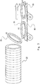
pipe 22 is cut in a direction perpendicular to the central axis of thepipe 22 and rings 23 are thereby cut out from the pipe 22 (ST105). This step is one of the important features of the present invention and hence will be explained hereinafter in detail. - As an example, assume that one complete multi-layered ring is formed by layering nine layers of
rings 23 on one another. Further, assume that 18 rings 23 are cut out from asingle pipe 22 in the ring cutting-out step. That is, a plurality ofrings 23 corresponding to two of multi-layered rings are cut out from asingle pipe 22. -
Figs. 6 ,7 and8 show states where 18 rings 23 are cut out from asingle pipe 22. - The important point in this process is, when a plurality of rings 23 (18 rings 23 in this example) are cut out from a
single pipe 22, to keep the order of the cut-out rings 23 without changing it from the order in which these cut-out rings are originally located in the original pipe state before the cutting-out step. - (The truly important point is the mutual positional relation among the cut-out rings 23, i.e., the information on which of places these cut-out rings were originally located with respect to each other in the
pipe 22. However, for easier understanding, numbers assigned to the rings in an orderly manner from the right end of the pipe are used as information on the mutual positional relation in the pipe in the following explanation.) -
Fig. 6(a) shows apipe 22 beforerings 23 are cut out from it. Assume that numbers are assigned to sections of thispipe 22 at intervals corresponding to the width of therings 23 from the right end of thepipe 22. Since 18 rings 23 are cut out from thesingle pipe 22,numbers 1 to 18 are assigned at the predetermined width intervals from the right end of thepipe 22. Then, as shown inFig. 6(b) , thepipe 22 is cut in round slices from the right end. It should be noted that the order of therings 23 should be kept even after they are cut out. That is, therings 23 should be managed so that the mutual positional relation in the order of therings 23 is not disrupted. For example, as shown inFig. 7 , therings 23 may be cut out from the right end of thepipe 22 in the numerical order and the cut-out rings 23 may be conveyed by abelt conveyer 90 in the order in which they have been cut out. By doing so, the order of therings 23 can be kept without being disrupted (seeFig. 8 ). - Note that, for example, if the cut-out rings 23 are put in a tray in a disorderly manner irrespective of their order, the information on the mutual positional relation among the
rings 23, i.e., the information on which of places the rings are originally located with respect to each other in thepipe 22, is lost. Therefore, it is important to keep or manage the order of therings 23 after therings 23 are cut out from thepipe 22. - Any method capable of keeping the order of the
rings 23 may be used. That is, the method is not limited to any specific method. For example, therings 23 may be put in a belt conveyer, may be put in a turntable, or may be put in a tray in an orderly manner so that their order is kept. - Next, the cut-out rings are polished (ST106). Burrs are removed and corners are rounded (chamfering). It is also important to keep the order of the
rings 23 so that it is not disrupted in this polishing process. - For example, each of the rings may be polished one by one by using a brush. Alternatively, removal of burrs and rounding (chamfering) for the rings may be performed one by one by laser for each ring. Further, each of the rings may be polished one by one by using a barrel.
- Note that it is important to keep the order of the rings in the polishing process. Therefore, for example, it is undesirable to barrel-polish the rings all together at the same time.
- After the polishing (ST106), washing (ST107), rolling (ST108), washing (ST109), and a second solution heat treatment (ST110) are performed in this order. The process in each of these steps is known. However, it is important to keep the order of the
rings 23 throughout these steps. - Note that in the rolling (ST108), each of the
rings 23 is rolled so as to have a predetermined thickness. For example, each of therings 23 is sandwiched between a pair of reduction rollers in the thickness direction and a pressure is applied thereto. - In the second solution heat treatment (ST110), heating and cooling are performed in order to restore the metal structure of the rings, which has been deformed by the rolling (ST108), to the original state.
- Next, the circumferential lengths of the rolled (i.e., flattened) rings 23 are adjusted so that they exhibit circumferential lengths respectively predetermined for them (ST111). That is, the
rings 23 are stretched and adjusted by applying a tension (tensile force) so that they have determined circumferential lengths. - Note that there are predetermined target values for circumferential lengths for these rings, i.e., the ring that will become the first ring, the ring that will become the second ring, and so on.
- For this process in which the
rings 23 are stretched by applying a tension (tensile force), contrivances are made to prevent the durability of therings 23 from deteriorating while adjusting their circumferential lengths with a very high accuracy. (For example, Japanese Unexamined Patent Application Publications No.2011-185300 2013-52432 - Note that one of the important points in this exemplary embodiment is that rings that are adjacent to each other in the
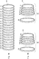
pipe 22 become layers that are adjacent to each other even when they are assembled into a multi-layered ring.Fig. 9 shows rings that will be subjected to a circumferential length adjustment process, in which the rings are arranged so that their original order is kept. Throughout the preceding steps, the rings have been managed so that their mutual relation in the order is not disrupted. Therefore, it can be understood that therings 23 can be arranged so that their original order is kept as shown inFig. 9(a) . - In this exemplary embodiment, 18 rings 23 are cut out from a
single pipe 22 and two of multi-layered rings are created. Therefore, one of the two of multi-layered rings is referred to as a "firstmulti-layered ring 12A" and the other multi layered ring is referred to as a "secondmulti-layered ring 12B". - Further, the innermost ring in a multi-layered ring is referred to as a "first ring" and the ring layered on the outer side of the first ring is referred to as a "second ring". Further, the other rings are named in such a manner that their numbers increase from the inner side to the outer side of the rings.
- Note that the first
multi-layered ring 12A should be formed so that the first ring (1) becomes the first ring of the firstmulti-layered ring 12A (seeFig. 9(b) ). - The second ring (2) becomes the second ring of the first
multi-layered ring 12A. - The third ring (3) becomes the third ring of the first
multi-layered ring 12A. - The remaining rings are assembled in a similar manner and the ninth ring (9) becomes the ninth ring of the first
multi-layered ring 12A. - In other words, the first ring (1) is adjusted so as to have the circumferential length of the first ring of the multi-layered ring. The second ring (2) is adjusted so as to have the circumferential length of the second ring of the multi-layered ring, and so on.
- The second
multi-layered ring 12B is formed in a manner similar to the manner in which firstmulti-layered ring 12A is formed. That is, the 10th ring (10) becomes the first ring of the secondmulti-layered ring 12B. - The 11th ring (11) becomes the second ring of the second
multi-layered ring 12B. - The 12th ring (12) becomes the third ring of the second
multi-layered ring 12B. The remaining rings are assembled in a similar manner and the 18th ring (18) becomes the ninth ring of the secondmulti-layered ring 12B. -
Fig. 9(b) schematically shows a state after circumferential length adjustments are performed for therings 23 so that they have target circumferential lengths for the respective layers. - Subsequent to the circumferential length adjustment (ST111), a preparation for the heat treatment is made. That is, to convey the rings, for which the circumferential length adjustment (ST111) has been performed, to a heat treatment furnace, the
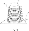
rings 23 are set (i.e., put) in aring loading jig 80.Fig. 10 shows a state where therings 23 are set in thering loading jig 80. - One of the important points in this exemplary embodiment is that rings that become layers adjacent to each other in the multi-layered ring should be subjected to the heat treatment under roughly the same condition. In other words, rings that become layers adjacent to each other in the multi-layered ring should undergo the heat treatment while keeping their positions as close to each other as possible.
- A set of rings, which will be assembled into one multi-layered ring in the future, are set in the ring loading jig.
-
Fig. 9 shows an example of the ring loading jig. - The
ring loading jig 80 includes abottom plate 81 and apost 82 disposed in thebottom plate 81 in a standing position, and thepost 82 includes a plurality of flanges (not shown). - The
ring loading jig 80 is configured so that therings 23 are hooked by the flanges. In this way, a set of the rings 23 (i.e., nine rings 23) can be set in onering loading jig 80. - Then, as described previously, since it is preferable that rings that become layers adjacent to each other in the multi-layered ring be subject to the heat treatment under roughly the same condition, the
rings 23 are preferably set in thering loading jig 80 so that rings that become layers adjacent to each other in the multi-layered ring are disposed adjacent to each other. In the example shown inFig. 10 , the first ring (i.e., the first ring of the multi-layered ring) is placed in the uppermost position and the second ring (i.e., the second ring of the multi-layered ring) is placed immediately below the first ring. Further, the third ring (i.e., the third ring of the multi-layered ring) is placed immediately below the second ring. (Since the remaining rings are placed in a similar fashion, explanations thereof are omitted.) - The
ring loading jig 80, in which therings 23 are set, is placed on a conveyer (not shown) (ST114) and sent to the heat treatment furnace. - The heat treatment itself is a well-known process, in which aging (ST115), oxidizing (ST116), and nitriding (ST117) are performed for the
rings 23. - In the aging process (ST115), the rings are heated to a predetermined temperature, left at the raised temperature for a sufficient time period, and then cooled.
- In the oxidizing process (ST116), the rings are subjected to an oxidizing process at a predetermined oxidizing process temperature in an oxidizing atmosphere, and an oxide layer is thereby generated.
- In the nitriding process (ST117), the rings are subjected to a nitriding process at a predetermined nitriding process temperature in a nitriding atmosphere, and a nitride layer is thereby generated.
- The heat treatment furnace incudes a plurality of processing chambers partitioned by doors, and the
ring loading jig 80 is successively passed through each of the processing chambers by the conveyer. - Upon completing the heat treatment (ST115 to ST117), the conveyer is carried out from the heat treatment furnace (ST118). The
rings 23, for which the heat treatment has been performed, are subjected to a predetermined inspection(s) (e.g., a surface inspection ST119) and then assembled into amulti-layered ring 12. Note that since a set ofrings 23, which are assembled into themulti-layered ring 12, are set in onering loading jig 80, the ninerings 23 set in the onering loading jig 80 may be assembled into themulti-layered ring 12 without adding or removing any rings. - After that, the
multi-layered ring 12 produced in the above-described manner may be shipped. - The above-described first exemplary embodiment provides the following advantageous effects.
- One of the features of the first exemplary embodiment is that rings that are adjacent to each other in the
pipe 22 become layers that are adjacent to each other even when they are assembled into themulti-layered ring 12. - Note that it is unavoidable that the
roll 20, which is the raw material, has some variations in plate thickness and material composition according to the place within theroll 20. (For example, regarding the plate thickness, it fluctuates by about 3 µm to 4 µm according to the place.) Further, the steel plate is bent and then both ends of it are welded together to create thepipe 22 as described above, and it is thus unavoidable that the welding quality varies according to the place within theroll 20. - Note that there is a problem that even when variations in various factors such as the material composition, plate thickness, and the welding quality are within their respective specification ranges, the amounts of the elongations of the rings after the heat treatment differ from one ring to another.
- For example, even when materials whose variations in various factors such as the material composition, plate thickness, and the welding quality are within their respective specification ranges are subjected to heat treatments under the same condition, the variations in the amounts of the elongations of the rings could be about several hundred µm on either of the positive and negative sides.
- Therefore, there have been many cases where even when the circumferential lengths can be accurately adjusted to their target values by the circumferential length process, which is performed before the heat treatment, the adjusted rings cannot be layered on each other according to the plan after the heat treatment. These cases have caused such troubles that the circumferential lengths of all the rings have to be measured and they have to be selectively used according to the measured circumferential lengths for the assembling.
- Regarding this point, in this exemplary embodiment, rings that are adjacent to each other in the
pipe 22 become layers that are adjacent to each other even when they are assembled into themulti-layered ring 12. It can be expected that rings that are adjacent to each other in thepipe 22 have substantially the same compositions, plate thicknesses, and welding quality. Further, in this exemplary embodiment, rings that become layers adjacent to each other in themulti-layered ring 12 are subjected to the heat treatment under roughly the same condition. Therefore, it can be expected that, for layers that are adjacent to each other in amulti-layered ring 12, even if they elongate to some degree in the heat treatment, their elongations have substantially the same tendencies. Therefore, the ninerings 23 can be assembled into the nine layers constituting themulti-layered ring 12 exactly according to the order of therings 23 at the time when they are set in thering loading jig 80. This leads to the elimination of the tasks of measuring the length of therings 23, sorting out of the rings, and selecting the rings after the heat treatment, and consequently reduces the troublesome processes and the cost and improves the production efficiency. - Modified example 1 according to the present invention is explained.
- The feature that "rings that are adjacent to each other in a pipe become layers that are adjacent to each other even when they are assembled into a multi-layered ring" in the first exemplary embodiment is considered to a best mode in that the variations among adjacent layers after the heat treatment is reduced to the limit. However, in view of the fact that each of the cut-out rings 23 has to be successively processed in turn, there is a problem that the load on the manufacturing process management is large. Note that an ultimate object (i.e., the minimum requirement) is that the rings can be eventually assembled into a
multi-layered ring 12 and the assembledmulti-layered ring 12 satisfies the specifications as the multi-layered ring 12 (such as an inter-layer clearance). Therefore, some replacement in the order of the rings is allowed as long as the above-described object can be attained. - For example, as shown in
Fig. 11 , the order of rings can be changed within a set of rings (e.g., nine rings) that will form one multi-layered ring. - In the example shown in
Fig. 11 , two of multi-layered rings are created from asingle pipe 22. - A first multi-layered ring is obtained from the right half of the
pipe 22 and a second multi-layered ring is obtained from the left half of thepipe 22. (InFig. 11 , due to the width of the paper, the illustration for the second multi-layered ring is omitted.) That is, the first to ninth rings constituting the first multi-layered ring are cut out from the right half of thepipe 22. - Note that the order of the nine rings cut out from the right half of the
pipe 22 does not need to be managed. That is, after the ninerings 23 are cut out from the right half of thepipe 22, they may be processed in a batch. - For example, the nine rings 23 may be barrel-polished together.
- This leads to the loss of the information on the order of the nine rings. However, it can be expected that when the disruption in the order of rings is in the degree corresponding to one set of rings (e.g., nine rings) constituting one multi-layered ring, their compositions, plate thicknesses, and welding quality do not widely vary from one another even when their places in the pipe are apart from each other.
- One of the nine rings is used as the first ring and one of the remaining rings is used as the second ring. Further, one of the remaining rings used as the third rings, and so on (the explanation of the remaining is omitted).
- As a result, as shown in
Fig. 11(c) , the first ring (1) and the ninth ring (9), for example, could become layers adjacent to each other.
Fig. 11(c) shows an example where the first ring (1) becomes the fourth ring of the multi-layered ring and the ninth ring becomes the fifth ring of the multi-layered ring.
(Needless to say, in actuality, the information on the correspondence, i.e., information as to which rings are in which positions is already lost. Therefore, in the figure, the numbers are arbitrarily assigned.) - Even in the above-described case, it can be expected that since the compositions, the plate thicknesses, and the welding quality do not widely vary from one another, the variations in the inter-layer clearance is very small even when the rings are elongated to some degree due to the heat treatment.
- When the first to ninth rings constituting the second multi-layered ring are obtained from the left half of the
pipe 22, the 10th to 18th rings may be shuffled. Since the reason for this is similar to that for first multi-layered ring, repetitive explanations are omitted. - Further, Modified example 2 is explained.
- In Modified example 2, replacement in the order of rings is allowed as long as it is made from a single pipe. That is, 18 rings may be cut out from a single pipe and they may be processed in a batch.
- For example, 18 rings 23 may be barrel-polished together.
- This leads to the loss of the information on the order of 18 rings. However, it can be expected that when all the rings are obtained from the same pipe, their compositions, plate thicknesses, and welding quality do not widely vary from one another even when their places in the pipe are apart from each other. The first multi-layered ring is created by using half of 18 rings and the second multi-layered ring is created by using the other half.
- As a result, as shown in
Fig. 12 , the first ring (1) and the 18th ring (18), for example, could become layers adjacent to each other. Even in the above-described case, it can be expected that since the compositions, the plate thicknesses, and the welding quality do not widely vary from one another, the variations in the inter-layer clearance is very small even when the rings are elongated to some degree due to the heat treatment. - Note that the present invention is not limited to the above-described first exemplary embodiment, and it can be modified as appropriate without departing from the sprit and scope of the present invention.
- In the first exemplary embodiment, an example where each of cut-out rings is processed in turn in the subsequent processes so that the order of the cut-out rings is not changed is shown. The simplest way is to put the cut-out rings in an assembly-line system in the order in which they have been cut out so that their order is not changed. However, needless to say, there is room for various contrivances in order to improve the production efficiency.
- For example, some information may be added to the rings so that they can be keep track of at a later time. For example, each of the cut-out rings may be marked so that their order can be recognized. By doing so, even when the rings are subjected to the polishing process in a batch, for example, they can be rearranged according to the original order prior to the circumferential length adjustment process and the heat treatment.
- Alternatively, a plurality of rings may be processed in parallel in a plurality of lanes, provided that the order of the rings can be managed. That is, various contrivances may be made for the actual production processes.
- This application is based upon and claims the benefit of priority from Japanese patent application No.
2013-132604, filed on June 25, 2013 -
- 10
- ENDLESS METAL BELT
- 11
- METAL ELEMENT
- 12
- MULTI-LAYERED RING
- 13
-
ENDLESS METAL RING 20 ROLL - 21
- STEEL PLATE
- 22
- PIPE
- 23
- RING
- 80
- RING LOADING JIG
- 81
- BOTTOM PLATE
- 82
- POST
- 90
- BELT CONVEYER
Claims (6)
- A manufacturing method for a multi-layered ring, the multi-layered ring being formed by layering a plurality of endless metal rings having slightly different circumferential lengths on one another, the manufacturing method comprising:a welding step of welding ends of a steel plate together and thereby forming a cylindrical pipe;a ring cutting-out step of cutting the pipe at a predetermined width in a direction perpendicular to a central axis of the pipe and thereby cutting out a plurality of rings;a polishing step of polishing the rings;a circumferential length adjustment step of adjusting the plurality of rings so that they exhibit circumferential lengths respectively predetermined for them;a nitriding step of nitriding the plurality of rings; andan assembling step of assembling in order to layer the plurality of rings into a multi-layered ring, whereinthe assembling step is performed so that rings that were parts originally adjacent to each other in a state of the pipe become layers that are adjacent to each other in the multi-layered ring.
- The manufacturing method for a multi-layered ring according to Claim 1, wherein in the polishing step, each of the plurality of rings is polished one by one so that an order in which the plurality of rings are cut out in the cutting-out step can be kept track of.
- The manufacturing method for a multi-layered ring according to Claim 1 or 2,
wherein the nitriding step is performed in a state where the plurality of rings are set in a jig in such a manner that rings that were parts originally adjacent to each other in the state of the pipe are disposed adjacent to each other in the jig. - The manufacturing method for a multi-layered ring according to any one of Claims 1 to 3, wherein in the circumferential length adjustment step, the circumferential length of each ring is adjusted so that rings that were parts originally adjacent to each other in the state of the pipe become layers that are adjacent to each other in the multi-layered ring.
- A manufacturing method for a multi-layered ring, the multi-layered ring being formed by layering a plurality of endless metal rings having slightly different circumferential lengths on one another, the manufacturing method comprising:a welding step of welding ends of a steel plate together and thereby forming a cylindrical pipe;a ring cutting-out step of cutting the pipe at a predetermined width in a direction perpendicular to a central axis of the pipe and thereby cutting out a plurality of rings;a polishing step of polishing the rings;a circumferential length adjustment step of adjusting the plurality of rings so that they exhibit circumferential lengths respectively predetermined for them;a nitriding step of nitriding the plurality of rings; andan assembling step of assembling in order to layer the plurality of rings into a multi-layered ring, whereinin the assembling step, a predetermined number of rings among the plurality of rings cut out from a single pipe are assembled into one multi-layered ring.
- A manufacturing method for a multi-layered ring, the multi-layered ring being formed by layering a plurality of endless metal rings having slightly different circumferential lengths on one another, the manufacturing method comprising:a welding step of welding ends of a steel plate together and thereby forming a cylindrical pipe;a ring cutting-out step of cutting the pipe at a predetermined width in a direction perpendicular to a central axis of the pipe and thereby cutting out a plurality of rings;a polishing step of polishing the rings;a circumferential length adjustment step of adjusting the plurality of rings so that they exhibit circumferential lengths respectively predetermined for them;a nitriding step of nitriding the plurality of rings; andan assembling step of assembling in order to layer the plurality of rings into a multi-layered ring, whereinin the assembling step, a predetermined number of rings among the plurality of rings cut out from a part of the pipe which has length of a half of the pipe are assembled into one multi-layered ring.
Applications Claiming Priority (2)
| Application Number | Priority Date | Filing Date | Title |
|---|---|---|---|
| JP2013132604A JP6036574B2 (en) | 2013-06-25 | 2013-06-25 | Manufacturing method of laminated ring |
| PCT/JP2014/002551 WO2014207984A1 (en) | 2013-06-25 | 2014-05-14 | Method for manufacturing laminated rings |
Publications (3)
| Publication Number | Publication Date |
|---|---|
| EP3015564A1 true EP3015564A1 (en) | 2016-05-04 |
| EP3015564A4 EP3015564A4 (en) | 2016-06-22 |
| EP3015564B1 EP3015564B1 (en) | 2018-06-20 |
Family
ID=52141361
Family Applications (1)
| Application Number | Title | Priority Date | Filing Date |
|---|---|---|---|
| EP14817076.4A Not-in-force EP3015564B1 (en) | 2013-06-25 | 2014-05-14 | Manufacturing method for multi-layered ring |
Country Status (5)
| Country | Link |
|---|---|
| US (1) | US10088013B2 (en) |
| EP (1) | EP3015564B1 (en) |
| JP (1) | JP6036574B2 (en) |
| CN (1) | CN105358731B (en) |
| WO (1) | WO2014207984A1 (en) |
Families Citing this family (6)
| Publication number | Priority date | Publication date | Assignee | Title |
|---|---|---|---|---|
| CN106271423B (en) * | 2016-08-26 | 2018-08-31 | 中航动力股份有限公司 | A kind of processing method of alloy type thin walled welds washer |
| JP2018054081A (en) * | 2016-09-30 | 2018-04-05 | アイシン・エィ・ダブリュ株式会社 | Ring manufacturing method |
| WO2018062549A1 (en) * | 2016-09-30 | 2018-04-05 | アイシン・エィ・ダブリュ株式会社 | Method of cleaning portion to be welded, welding system, and method of manufacturing ring |
| PL234237B1 (en) * | 2017-10-19 | 2020-01-31 | Instytut Mech Precyzyjnej | Method for glow-discharge nitriding of inner surfaces of bushings, preferably barrels |
| JP2019177403A (en) * | 2018-03-30 | 2019-10-17 | トヨタ自動車株式会社 | Manufacturing method of endless metal ring |
| CN111571129A (en) * | 2020-05-11 | 2020-08-25 | 哈尔滨锅炉厂有限责任公司 | Manufacturing method of large-diameter thin-wall circular ring of pressure-bearing equipment |
Family Cites Families (11)
| Publication number | Priority date | Publication date | Assignee | Title |
|---|---|---|---|---|
| US6631542B1 (en) * | 1999-05-28 | 2003-10-14 | Honda Giken Kogyo Kabushiki Kaisha | Method of manufacturing laminated ring and heat treatment apparatus for use in such method |
| JP3779129B2 (en) * | 2000-05-18 | 2006-05-24 | 本田技研工業株式会社 | Heat treatment method |
| JP3884246B2 (en) | 2001-08-08 | 2007-02-21 | 本田技研工業株式会社 | CVT belt hoop manufacturing method |
| JP4429559B2 (en) * | 2001-09-27 | 2010-03-10 | 本田技研工業株式会社 | Manufacturing method of metal laminated ring |
| JP2005155755A (en) | 2003-11-25 | 2005-06-16 | Toyota Motor Corp | Manufacturing apparatus and manufacturing method of endless metal ring used for continuously variable transmission |
| JP2005337339A (en) * | 2004-05-25 | 2005-12-08 | Honda Motor Co Ltd | Method for producing endless metal belt |
| JP2009249646A (en) | 2008-04-01 | 2009-10-29 | Toyota Motor Corp | Method for manufacturing hoop, and manufacturing apparatus therefor |
| KR101080533B1 (en) * | 2009-02-09 | 2011-11-04 | 김지현 | Manufacturing method for round cutting bites making remaining materials reusable |
| WO2011077579A1 (en) | 2009-12-25 | 2011-06-30 | トヨタ自動車株式会社 | Method for producing laminated ring |
| JP5494025B2 (en) | 2010-03-04 | 2014-05-14 | トヨタ自動車株式会社 | Manufacturing method of laminated ring |
| JP5776455B2 (en) * | 2011-09-06 | 2015-09-09 | トヨタ自動車株式会社 | Endless metal ring manufacturing apparatus and manufacturing method |
-
2013
- 2013-06-25 JP JP2013132604A patent/JP6036574B2/en not_active Expired - Fee Related
-
2014
- 2014-05-14 EP EP14817076.4A patent/EP3015564B1/en not_active Not-in-force
- 2014-05-14 US US14/898,586 patent/US10088013B2/en not_active Expired - Fee Related
- 2014-05-14 WO PCT/JP2014/002551 patent/WO2014207984A1/en not_active Ceased
- 2014-05-14 CN CN201480036712.7A patent/CN105358731B/en not_active Expired - Fee Related
Also Published As
| Publication number | Publication date |
|---|---|
| JP6036574B2 (en) | 2016-11-30 |
| EP3015564A4 (en) | 2016-06-22 |
| CN105358731A (en) | 2016-02-24 |
| EP3015564B1 (en) | 2018-06-20 |
| CN105358731B (en) | 2017-05-17 |
| US10088013B2 (en) | 2018-10-02 |
| WO2014207984A1 (en) | 2014-12-31 |
| JP2015007270A (en) | 2015-01-15 |
| US20160138674A1 (en) | 2016-05-19 |
Similar Documents
| Publication | Publication Date | Title |
|---|---|---|
| EP3015564B1 (en) | Manufacturing method for multi-layered ring | |
| US9982749B2 (en) | Method for manufacturing endless metal belt, endless metal belt, and belt-type continuously variable transmission | |
| EP1815160B1 (en) | Push belt and manufacturing method therefor | |
| CN102308118B (en) | Metal ring and its manufacturing method | |
| EP2889104B1 (en) | Method for forming a carrier ring suitable for use in a drive belt for a continuously variable transmission | |
| NL1043109B1 (en) | Method for manufacturing a metal ring for a ring set of a drive belt for a continuously variable transmission | |
| JP5776455B2 (en) | Endless metal ring manufacturing apparatus and manufacturing method | |
| KR20120083882A (en) | Drive belt provided with a laminated set of steel rings | |
| JP5333609B2 (en) | Transmission belt and manufacturing method thereof | |
| JP5322122B2 (en) | Method for manufacturing a transverse element for a drive belt | |
| JP2012206131A (en) | Method of manufacturing thin endless metal ring | |
| JP4546843B2 (en) | Thrust bearing washer manufacturing method and thrust bearing manufacturing method | |
| NL1043108B1 (en) | Method for manufacturing a drive belt for a continuously variable transmission and a drive belt thus manufactured | |
| US10955028B2 (en) | Transmission belt | |
| EP2018245B1 (en) | Manufacturing method for a laminated set of metal rings for a pushbelt and pushbelt | |
| NL1043882B1 (en) | Ring circumference length calibration process in a manufacturing method of a ring set for a drive belt | |
| JP4546844B2 (en) | Thrust bearing washer manufacturing method and thrust bearing manufacturing method | |
| JP5776531B2 (en) | Endless metal ring manufacturing apparatus and manufacturing method | |
| WO2022128046A1 (en) | Ring circumference length calibration process in a manufacturing method of a ring set for a drive belt | |
| WO2022128043A1 (en) | Method for manufacturing a metal ring for a ring-set of a drive belt for a continuously variable transmission | |
| EP2985090A1 (en) | Cvt belt manufacturing method |
Legal Events
| Date | Code | Title | Description |
|---|---|---|---|
| PUAI | Public reference made under article 153(3) epc to a published international application that has entered the european phase |
Free format text: ORIGINAL CODE: 0009012 |
|
| 17P | Request for examination filed |
Effective date: 20151210 |
|
| AK | Designated contracting states |
Kind code of ref document: A1 Designated state(s): AL AT BE BG CH CY CZ DE DK EE ES FI FR GB GR HR HU IE IS IT LI LT LU LV MC MK MT NL NO PL PT RO RS SE SI SK SM TR |
|
| AX | Request for extension of the european patent |
Extension state: BA ME |
|
| A4 | Supplementary search report drawn up and despatched |
Effective date: 20160523 |
|
| RIC1 | Information provided on ipc code assigned before grant |
Ipc: C23C 8/02 20060101ALI20160517BHEP Ipc: B23P 15/00 20060101ALI20160517BHEP Ipc: C21D 9/40 20060101ALI20160517BHEP Ipc: B21D 53/16 20060101ALI20160517BHEP Ipc: C23C 8/26 20060101AFI20160517BHEP Ipc: C21D 9/50 20060101ALI20160517BHEP Ipc: C23C 8/10 20060101ALI20160517BHEP Ipc: F16G 5/16 20060101ALI20160517BHEP Ipc: C23C 8/34 20060101ALI20160517BHEP |
|
| DAX | Request for extension of the european patent (deleted) | ||
| GRAP | Despatch of communication of intention to grant a patent |
Free format text: ORIGINAL CODE: EPIDOSNIGR1 |
|
| STAA | Information on the status of an ep patent application or granted ep patent |
Free format text: STATUS: GRANT OF PATENT IS INTENDED |
|
| RIC1 | Information provided on ipc code assigned before grant |
Ipc: B23P 15/00 20060101ALI20180126BHEP Ipc: C23C 8/26 20060101AFI20180126BHEP Ipc: C23C 8/10 20060101ALI20180126BHEP Ipc: F16G 5/16 20060101ALI20180126BHEP Ipc: C21D 9/40 20060101ALI20180126BHEP Ipc: C23C 8/02 20060101ALI20180126BHEP Ipc: C21D 9/50 20060101ALI20180126BHEP Ipc: B21D 53/16 20060101ALI20180126BHEP Ipc: C23C 8/34 20060101ALI20180126BHEP |
|
| INTG | Intention to grant announced |
Effective date: 20180227 |
|
| GRAS | Grant fee paid |
Free format text: ORIGINAL CODE: EPIDOSNIGR3 |
|
| GRAA | (expected) grant |
Free format text: ORIGINAL CODE: 0009210 |
|
| STAA | Information on the status of an ep patent application or granted ep patent |
Free format text: STATUS: THE PATENT HAS BEEN GRANTED |
|
| AK | Designated contracting states |
Kind code of ref document: B1 Designated state(s): AL AT BE BG CH CY CZ DE DK EE ES FI FR GB GR HR HU IE IS IT LI LT LU LV MC MK MT NL NO PL PT RO RS SE SI SK SM TR |
|
| REG | Reference to a national code |
Ref country code: GB Ref legal event code: FG4D |
|
| REG | Reference to a national code |
Ref country code: IE Ref legal event code: FG4D |
|
| REG | Reference to a national code |
Ref country code: DE Ref legal event code: R096 Ref document number: 602014027360 Country of ref document: DE |
|
| REG | Reference to a national code |
Ref country code: AT Ref legal event code: REF Ref document number: 1010660 Country of ref document: AT Kind code of ref document: T Effective date: 20180715 |
|
| REG | Reference to a national code |
Ref country code: NL Ref legal event code: FP |
|
| REG | Reference to a national code |
Ref country code: DE Ref legal event code: R084 Ref document number: 602014027360 Country of ref document: DE |
|
| PG25 | Lapsed in a contracting state [announced via postgrant information from national office to epo] |
Ref country code: LT Free format text: LAPSE BECAUSE OF FAILURE TO SUBMIT A TRANSLATION OF THE DESCRIPTION OR TO PAY THE FEE WITHIN THE PRESCRIBED TIME-LIMIT Effective date: 20180620 Ref country code: SE Free format text: LAPSE BECAUSE OF FAILURE TO SUBMIT A TRANSLATION OF THE DESCRIPTION OR TO PAY THE FEE WITHIN THE PRESCRIBED TIME-LIMIT Effective date: 20180620 Ref country code: NO Free format text: LAPSE BECAUSE OF FAILURE TO SUBMIT A TRANSLATION OF THE DESCRIPTION OR TO PAY THE FEE WITHIN THE PRESCRIBED TIME-LIMIT Effective date: 20180920 Ref country code: BG Free format text: LAPSE BECAUSE OF FAILURE TO SUBMIT A TRANSLATION OF THE DESCRIPTION OR TO PAY THE FEE WITHIN THE PRESCRIBED TIME-LIMIT Effective date: 20180920 Ref country code: FI Free format text: LAPSE BECAUSE OF FAILURE TO SUBMIT A TRANSLATION OF THE DESCRIPTION OR TO PAY THE FEE WITHIN THE PRESCRIBED TIME-LIMIT Effective date: 20180620 |
|
| REG | Reference to a national code |
Ref country code: LT Ref legal event code: MG4D |
|
| PG25 | Lapsed in a contracting state [announced via postgrant information from national office to epo] |
Ref country code: LV Free format text: LAPSE BECAUSE OF FAILURE TO SUBMIT A TRANSLATION OF THE DESCRIPTION OR TO PAY THE FEE WITHIN THE PRESCRIBED TIME-LIMIT Effective date: 20180620 Ref country code: HR Free format text: LAPSE BECAUSE OF FAILURE TO SUBMIT A TRANSLATION OF THE DESCRIPTION OR TO PAY THE FEE WITHIN THE PRESCRIBED TIME-LIMIT Effective date: 20180620 Ref country code: GR Free format text: LAPSE BECAUSE OF FAILURE TO SUBMIT A TRANSLATION OF THE DESCRIPTION OR TO PAY THE FEE WITHIN THE PRESCRIBED TIME-LIMIT Effective date: 20180921 Ref country code: RS Free format text: LAPSE BECAUSE OF FAILURE TO SUBMIT A TRANSLATION OF THE DESCRIPTION OR TO PAY THE FEE WITHIN THE PRESCRIBED TIME-LIMIT Effective date: 20180620 |
|
| REG | Reference to a national code |
Ref country code: AT Ref legal event code: MK05 Ref document number: 1010660 Country of ref document: AT Kind code of ref document: T Effective date: 20180620 |
|
| PG25 | Lapsed in a contracting state [announced via postgrant information from national office to epo] |
Ref country code: AT Free format text: LAPSE BECAUSE OF FAILURE TO SUBMIT A TRANSLATION OF THE DESCRIPTION OR TO PAY THE FEE WITHIN THE PRESCRIBED TIME-LIMIT Effective date: 20180620 Ref country code: IS Free format text: LAPSE BECAUSE OF FAILURE TO SUBMIT A TRANSLATION OF THE DESCRIPTION OR TO PAY THE FEE WITHIN THE PRESCRIBED TIME-LIMIT Effective date: 20181020 Ref country code: EE Free format text: LAPSE BECAUSE OF FAILURE TO SUBMIT A TRANSLATION OF THE DESCRIPTION OR TO PAY THE FEE WITHIN THE PRESCRIBED TIME-LIMIT Effective date: 20180620 Ref country code: CZ Free format text: LAPSE BECAUSE OF FAILURE TO SUBMIT A TRANSLATION OF THE DESCRIPTION OR TO PAY THE FEE WITHIN THE PRESCRIBED TIME-LIMIT Effective date: 20180620 Ref country code: RO Free format text: LAPSE BECAUSE OF FAILURE TO SUBMIT A TRANSLATION OF THE DESCRIPTION OR TO PAY THE FEE WITHIN THE PRESCRIBED TIME-LIMIT Effective date: 20180620 Ref country code: PL Free format text: LAPSE BECAUSE OF FAILURE TO SUBMIT A TRANSLATION OF THE DESCRIPTION OR TO PAY THE FEE WITHIN THE PRESCRIBED TIME-LIMIT Effective date: 20180620 Ref country code: SK Free format text: LAPSE BECAUSE OF FAILURE TO SUBMIT A TRANSLATION OF THE DESCRIPTION OR TO PAY THE FEE WITHIN THE PRESCRIBED TIME-LIMIT Effective date: 20180620 |
|
| PG25 | Lapsed in a contracting state [announced via postgrant information from national office to epo] |
Ref country code: ES Free format text: LAPSE BECAUSE OF FAILURE TO SUBMIT A TRANSLATION OF THE DESCRIPTION OR TO PAY THE FEE WITHIN THE PRESCRIBED TIME-LIMIT Effective date: 20180620 Ref country code: IT Free format text: LAPSE BECAUSE OF FAILURE TO SUBMIT A TRANSLATION OF THE DESCRIPTION OR TO PAY THE FEE WITHIN THE PRESCRIBED TIME-LIMIT Effective date: 20180620 Ref country code: SM Free format text: LAPSE BECAUSE OF FAILURE TO SUBMIT A TRANSLATION OF THE DESCRIPTION OR TO PAY THE FEE WITHIN THE PRESCRIBED TIME-LIMIT Effective date: 20180620 |
|
| REG | Reference to a national code |
Ref country code: DE Ref legal event code: R097 Ref document number: 602014027360 Country of ref document: DE |
|
| PLBE | No opposition filed within time limit |
Free format text: ORIGINAL CODE: 0009261 |
|
| STAA | Information on the status of an ep patent application or granted ep patent |
Free format text: STATUS: NO OPPOSITION FILED WITHIN TIME LIMIT |
|
| 26N | No opposition filed |
Effective date: 20190321 |
|
| PG25 | Lapsed in a contracting state [announced via postgrant information from national office to epo] |
Ref country code: DK Free format text: LAPSE BECAUSE OF FAILURE TO SUBMIT A TRANSLATION OF THE DESCRIPTION OR TO PAY THE FEE WITHIN THE PRESCRIBED TIME-LIMIT Effective date: 20180620 |
|
| PG25 | Lapsed in a contracting state [announced via postgrant information from national office to epo] |
Ref country code: SI Free format text: LAPSE BECAUSE OF FAILURE TO SUBMIT A TRANSLATION OF THE DESCRIPTION OR TO PAY THE FEE WITHIN THE PRESCRIBED TIME-LIMIT Effective date: 20180620 |
|
| PG25 | Lapsed in a contracting state [announced via postgrant information from national office to epo] |
Ref country code: AL Free format text: LAPSE BECAUSE OF FAILURE TO SUBMIT A TRANSLATION OF THE DESCRIPTION OR TO PAY THE FEE WITHIN THE PRESCRIBED TIME-LIMIT Effective date: 20180620 |
|
| REG | Reference to a national code |
Ref country code: CH Ref legal event code: PL |
|
| GBPC | Gb: european patent ceased through non-payment of renewal fee |
Effective date: 20190514 |
|
| PG25 | Lapsed in a contracting state [announced via postgrant information from national office to epo] |
Ref country code: MC Free format text: LAPSE BECAUSE OF FAILURE TO SUBMIT A TRANSLATION OF THE DESCRIPTION OR TO PAY THE FEE WITHIN THE PRESCRIBED TIME-LIMIT Effective date: 20180620 Ref country code: LI Free format text: LAPSE BECAUSE OF NON-PAYMENT OF DUE FEES Effective date: 20190531 Ref country code: CH Free format text: LAPSE BECAUSE OF NON-PAYMENT OF DUE FEES Effective date: 20190531 |
|
| REG | Reference to a national code |
Ref country code: BE Ref legal event code: MM Effective date: 20190531 |
|
| PG25 | Lapsed in a contracting state [announced via postgrant information from national office to epo] |
Ref country code: LU Free format text: LAPSE BECAUSE OF NON-PAYMENT OF DUE FEES Effective date: 20190514 |
|
| PG25 | Lapsed in a contracting state [announced via postgrant information from national office to epo] |
Ref country code: TR Free format text: LAPSE BECAUSE OF FAILURE TO SUBMIT A TRANSLATION OF THE DESCRIPTION OR TO PAY THE FEE WITHIN THE PRESCRIBED TIME-LIMIT Effective date: 20180620 |
|
| PG25 | Lapsed in a contracting state [announced via postgrant information from national office to epo] |
Ref country code: IE Free format text: LAPSE BECAUSE OF NON-PAYMENT OF DUE FEES Effective date: 20190514 Ref country code: GB Free format text: LAPSE BECAUSE OF NON-PAYMENT OF DUE FEES Effective date: 20190514 |
|
| PG25 | Lapsed in a contracting state [announced via postgrant information from national office to epo] |
Ref country code: BE Free format text: LAPSE BECAUSE OF NON-PAYMENT OF DUE FEES Effective date: 20190531 |
|
| PG25 | Lapsed in a contracting state [announced via postgrant information from national office to epo] |
Ref country code: PT Free format text: LAPSE BECAUSE OF FAILURE TO SUBMIT A TRANSLATION OF THE DESCRIPTION OR TO PAY THE FEE WITHIN THE PRESCRIBED TIME-LIMIT Effective date: 20181022 Ref country code: FR Free format text: LAPSE BECAUSE OF NON-PAYMENT OF DUE FEES Effective date: 20190531 |
|
| PG25 | Lapsed in a contracting state [announced via postgrant information from national office to epo] |
Ref country code: CY Free format text: LAPSE BECAUSE OF FAILURE TO SUBMIT A TRANSLATION OF THE DESCRIPTION OR TO PAY THE FEE WITHIN THE PRESCRIBED TIME-LIMIT Effective date: 20180620 |
|
| PG25 | Lapsed in a contracting state [announced via postgrant information from national office to epo] |
Ref country code: HU Free format text: LAPSE BECAUSE OF FAILURE TO SUBMIT A TRANSLATION OF THE DESCRIPTION OR TO PAY THE FEE WITHIN THE PRESCRIBED TIME-LIMIT; INVALID AB INITIO Effective date: 20140514 Ref country code: MT Free format text: LAPSE BECAUSE OF FAILURE TO SUBMIT A TRANSLATION OF THE DESCRIPTION OR TO PAY THE FEE WITHIN THE PRESCRIBED TIME-LIMIT Effective date: 20180620 |
|
| PGFP | Annual fee paid to national office [announced via postgrant information from national office to epo] |
Ref country code: DE Payment date: 20210420 Year of fee payment: 8 |
|
| PGFP | Annual fee paid to national office [announced via postgrant information from national office to epo] |
Ref country code: NL Payment date: 20210415 Year of fee payment: 8 |
|
| PG25 | Lapsed in a contracting state [announced via postgrant information from national office to epo] |
Ref country code: MK Free format text: LAPSE BECAUSE OF FAILURE TO SUBMIT A TRANSLATION OF THE DESCRIPTION OR TO PAY THE FEE WITHIN THE PRESCRIBED TIME-LIMIT Effective date: 20180620 |
|
| REG | Reference to a national code |
Ref country code: DE Ref legal event code: R119 Ref document number: 602014027360 Country of ref document: DE |
|
| REG | Reference to a national code |
Ref country code: NL Ref legal event code: MM Effective date: 20220601 |
|
| PG25 | Lapsed in a contracting state [announced via postgrant information from national office to epo] |
Ref country code: DE Free format text: LAPSE BECAUSE OF NON-PAYMENT OF DUE FEES Effective date: 20221201 |
|
| PG25 | Lapsed in a contracting state [announced via postgrant information from national office to epo] |
Ref country code: NL Free format text: LAPSE BECAUSE OF NON-PAYMENT OF DUE FEES Effective date: 20220601 |