EP2889104B1 - Method for forming a carrier ring suitable for use in a drive belt for a continuously variable transmission - Google Patents
Method for forming a carrier ring suitable for use in a drive belt for a continuously variable transmission Download PDFInfo
- Publication number
- EP2889104B1 EP2889104B1 EP14197843.7A EP14197843A EP2889104B1 EP 2889104 B1 EP2889104 B1 EP 2889104B1 EP 14197843 A EP14197843 A EP 14197843A EP 2889104 B1 EP2889104 B1 EP 2889104B1
- Authority
- EP
- European Patent Office
- Prior art keywords
- strip
- drive belt
- welding
- ring
- carrier ring
- Prior art date
- Legal status (The legal status is an assumption and is not a legal conclusion. Google has not performed a legal analysis and makes no representation as to the accuracy of the status listed.)
- Active
Links
Images

Classifications
-
- B—PERFORMING OPERATIONS; TRANSPORTING
- B23—MACHINE TOOLS; METAL-WORKING NOT OTHERWISE PROVIDED FOR
- B23P—METAL-WORKING NOT OTHERWISE PROVIDED FOR; COMBINED OPERATIONS; UNIVERSAL MACHINE TOOLS
- B23P15/00—Making specific metal objects by operations not covered by a single other subclass or a group in this subclass
-
- B—PERFORMING OPERATIONS; TRANSPORTING
- B23—MACHINE TOOLS; METAL-WORKING NOT OTHERWISE PROVIDED FOR
- B23K—SOLDERING OR UNSOLDERING; WELDING; CLADDING OR PLATING BY SOLDERING OR WELDING; CUTTING BY APPLYING HEAT LOCALLY, e.g. FLAME CUTTING; WORKING BY LASER BEAM
- B23K26/00—Working by laser beam, e.g. welding, cutting or boring
- B23K26/08—Devices involving relative movement between laser beam and workpiece
- B23K26/0869—Devices involving movement of the laser head in at least one axial direction
-
- B—PERFORMING OPERATIONS; TRANSPORTING
- B23—MACHINE TOOLS; METAL-WORKING NOT OTHERWISE PROVIDED FOR
- B23K—SOLDERING OR UNSOLDERING; WELDING; CLADDING OR PLATING BY SOLDERING OR WELDING; CUTTING BY APPLYING HEAT LOCALLY, e.g. FLAME CUTTING; WORKING BY LASER BEAM
- B23K26/00—Working by laser beam, e.g. welding, cutting or boring
- B23K26/20—Bonding
- B23K26/21—Bonding by welding
- B23K26/24—Seam welding
- B23K26/26—Seam welding of rectilinear seams
-
- B—PERFORMING OPERATIONS; TRANSPORTING
- B23—MACHINE TOOLS; METAL-WORKING NOT OTHERWISE PROVIDED FOR
- B23K—SOLDERING OR UNSOLDERING; WELDING; CLADDING OR PLATING BY SOLDERING OR WELDING; CUTTING BY APPLYING HEAT LOCALLY, e.g. FLAME CUTTING; WORKING BY LASER BEAM
- B23K26/00—Working by laser beam, e.g. welding, cutting or boring
- B23K26/20—Bonding
- B23K26/32—Bonding taking account of the properties of the material involved
-
- B—PERFORMING OPERATIONS; TRANSPORTING
- B23—MACHINE TOOLS; METAL-WORKING NOT OTHERWISE PROVIDED FOR
- B23K—SOLDERING OR UNSOLDERING; WELDING; CLADDING OR PLATING BY SOLDERING OR WELDING; CUTTING BY APPLYING HEAT LOCALLY, e.g. FLAME CUTTING; WORKING BY LASER BEAM
- B23K9/00—Arc welding or cutting
- B23K9/0026—Arc welding or cutting specially adapted for particular articles or work
-
- B—PERFORMING OPERATIONS; TRANSPORTING
- B23—MACHINE TOOLS; METAL-WORKING NOT OTHERWISE PROVIDED FOR
- B23K—SOLDERING OR UNSOLDERING; WELDING; CLADDING OR PLATING BY SOLDERING OR WELDING; CUTTING BY APPLYING HEAT LOCALLY, e.g. FLAME CUTTING; WORKING BY LASER BEAM
- B23K9/00—Arc welding or cutting
- B23K9/02—Seam welding; Backing means; Inserts
- B23K9/025—Seam welding; Backing means; Inserts for rectilinear seams
-
- B—PERFORMING OPERATIONS; TRANSPORTING
- B23—MACHINE TOOLS; METAL-WORKING NOT OTHERWISE PROVIDED FOR
- B23K—SOLDERING OR UNSOLDERING; WELDING; CLADDING OR PLATING BY SOLDERING OR WELDING; CUTTING BY APPLYING HEAT LOCALLY, e.g. FLAME CUTTING; WORKING BY LASER BEAM
- B23K9/00—Arc welding or cutting
- B23K9/23—Arc welding or cutting taking account of the properties of the materials to be welded
-
- F—MECHANICAL ENGINEERING; LIGHTING; HEATING; WEAPONS; BLASTING
- F16—ENGINEERING ELEMENTS AND UNITS; GENERAL MEASURES FOR PRODUCING AND MAINTAINING EFFECTIVE FUNCTIONING OF MACHINES OR INSTALLATIONS; THERMAL INSULATION IN GENERAL
- F16G—BELTS, CABLES, OR ROPES, PREDOMINANTLY USED FOR DRIVING PURPOSES; CHAINS; FITTINGS PREDOMINANTLY USED THEREFOR
- F16G5/00—V-belts, i.e. belts of tapered cross-section
- F16G5/16—V-belts, i.e. belts of tapered cross-section consisting of several parts
-
- B—PERFORMING OPERATIONS; TRANSPORTING
- B21—MECHANICAL METAL-WORKING WITHOUT ESSENTIALLY REMOVING MATERIAL; PUNCHING METAL
- B21H—MAKING PARTICULAR METAL OBJECTS BY ROLLING, e.g. SCREWS, WHEELS, RINGS, BARRELS, BALLS
- B21H1/00—Making articles shaped as bodies of revolution
- B21H1/06—Making articles shaped as bodies of revolution rings of restricted axial length
-
- B—PERFORMING OPERATIONS; TRANSPORTING
- B21—MECHANICAL METAL-WORKING WITHOUT ESSENTIALLY REMOVING MATERIAL; PUNCHING METAL
- B21L—MAKING METAL CHAINS
- B21L3/00—Making chains or chain links by bending the chain links or link parts and subsequently welding or soldering the abutting ends
-
- B—PERFORMING OPERATIONS; TRANSPORTING
- B23—MACHINE TOOLS; METAL-WORKING NOT OTHERWISE PROVIDED FOR
- B23K—SOLDERING OR UNSOLDERING; WELDING; CLADDING OR PLATING BY SOLDERING OR WELDING; CUTTING BY APPLYING HEAT LOCALLY, e.g. FLAME CUTTING; WORKING BY LASER BEAM
- B23K2101/00—Articles made by soldering, welding or cutting
- B23K2101/006—Vehicles
-
- B—PERFORMING OPERATIONS; TRANSPORTING
- B23—MACHINE TOOLS; METAL-WORKING NOT OTHERWISE PROVIDED FOR
- B23K—SOLDERING OR UNSOLDERING; WELDING; CLADDING OR PLATING BY SOLDERING OR WELDING; CUTTING BY APPLYING HEAT LOCALLY, e.g. FLAME CUTTING; WORKING BY LASER BEAM
- B23K2101/00—Articles made by soldering, welding or cutting
- B23K2101/30—Chains, hoops or rings
-
- B—PERFORMING OPERATIONS; TRANSPORTING
- B23—MACHINE TOOLS; METAL-WORKING NOT OTHERWISE PROVIDED FOR
- B23K—SOLDERING OR UNSOLDERING; WELDING; CLADDING OR PLATING BY SOLDERING OR WELDING; CUTTING BY APPLYING HEAT LOCALLY, e.g. FLAME CUTTING; WORKING BY LASER BEAM
- B23K2103/00—Materials to be soldered, welded or cut
- B23K2103/02—Iron or ferrous alloys
- B23K2103/04—Steel or steel alloys
-
- B—PERFORMING OPERATIONS; TRANSPORTING
- B23—MACHINE TOOLS; METAL-WORKING NOT OTHERWISE PROVIDED FOR
- B23K—SOLDERING OR UNSOLDERING; WELDING; CLADDING OR PLATING BY SOLDERING OR WELDING; CUTTING BY APPLYING HEAT LOCALLY, e.g. FLAME CUTTING; WORKING BY LASER BEAM
- B23K2103/00—Materials to be soldered, welded or cut
- B23K2103/50—Inorganic material, e.g. metals, not provided for in B23K2103/02 – B23K2103/26
Definitions
- This disclosure relates to a method for forming a ring from steel basic material that is destined to function as a carrier of transverse elements in a closed-loop drive belt for a continuously variable transmission, comprising the following steps:
- a method according to the preamble of claim 1 is known from, for instance, the international patent application publication WO2009/ 132689-A1 . This document also discloses the preamble of product claim 2.
- a drive belt for a continuously variable transmission is generally known.
- a drive belt comprises two sets of endless, i.e. closed-loop rings that carry a multitude of transverse elements of the drive belt, which transverse elements are arranged in an essentially contiguous row along the entire circumference thereof.
- These carrier rings of the drive belt are relatively flat, i.e. the radial distance between an inner circumference and an outer circumference of the carrier rings is relatively small with respect to the dimension in an axial direction.
- the drive belt In a continuously variable transmission, the drive belt is disposed between two cooperating pulleys where between a continuously variable speed ratio is realized. During operation, the drive belt transmits a torque from one of the pulleys to the other one pulley, a/o by the transverse elements thereof pushing each other from the said one pulley to the said other one pulley.
- the carrier rings of the drive belt are exposed to bending and pulling forces.
- the bending forces are substantially determined by the thickness of the carrier rings and the extent to which ring portions are bent at the moments that they are present in the pulleys.
- the pulling forces are substantially determined by the tensile force with which the drive belt is suspended between both pulleys.
- metal fatigue of a carrier ring will play a role in a possible failure of the drive belt.
- Metal fatigue is related to the type and the quality of the used steel. For example, as a consequence of irregularities in the material, hair cracks may occur. Normally, such hair cracks will form at a location where the tension stress is highest. For the present carrier rings that are repeatedly bend such tension stress will normally be highest at or near its surface, a/o at or near the axial sides of the carrier ring.
- a basic material having the required material properties for drive belt application of the carrier ring is provided in, for instance, a coiled-up sheet form. From this basic material a strip is cut with length, width and thickness dimensions that are adapted to (obtain) the final carrier ring of required dimensions. The distal ends of the strip, as seen in the longitudinal direction thereof, are placed opposite one another and are fixed to one another by means of a welding process to form a continuous carrier ring. Typically, plasma-arc welding or laser welding is applied for this purpose, wherein a plasma arc or laser beam is passed from one axial side of the strip to the other one side thereof.
- the intensity of the plasma-arc or laser beam is set to melt a small part of both the said distal ends of the strip, which melted strip parts solidify into together as one once the plasma arc or laser beam has passed.
- the manufacture of the final carrier ring for the present drive belt application thereof is known to include several more processes such as rolling, hardening and nitriding.
- the said indentation is not necessarily formed to an equal extent on both axial sides of the carrier ring.
- the indentation is considerably larger on the axial side of the carrier ring where the welding process ends, i.e. where the plasma-arc or laser beam passes from the strip into the surroundings to complete the weld, as compared to the indentation formed on the opposite axial side of the carrier ring where the welding process was started, i.e. where the plasma-arc or laser beam first enters from the surroundings to in-between the distal ends of the strip.
- the present disclosure proposes to provide the weld in two phases, wherein, in a first phase of the welding process, the welding is started at a first axial side of the strip and is then continued towards the opposite axial side of the strip, however only to within the axial extent of the strip, where it is stopped, and wherein, in a second phase of the welding process, the welding is started at the opposite, i.e. second axial side of the strip and is then continued towards the first axial side of the strip, however, again only to within the axial extent of the strip.
- the welding in the second phase of the welding process is stopped only at a position that lies in the axial direction beyond the position where the welding was stopped in the first phase thereof.
- a weld (part) formed in the said second phase of the welding process partly overlaps with the weld (part) formed in the said first phase thereof.
- FIG 1 shows schematically a continuously variable transmission (CVT) with a drive belt 3 wrapped around two pulleys 1 and 2.
- Each pulley 1, 2 is provided with two conical pulley discs 4, 5, where between an annular, predominantly V-shaped pulley groove is defined and whereof one disc 4 is axially moveable along a respective pulley shaft 6, 7 over which it is placed.
- a drive belt 3 is wrapped around the pulleys 1, 2 for transmitting a rotational movement ⁇ and an accompanying torque T from the one pulley 1, 2 to the other 2, 1.
- Each pulley 1, 2 generally also comprises activation means that can impose on the said at least one disc 4 thereof an axially oriented clamping force directed towards the respective other pulley disc 5 thereof, such that the belt 3 can be clamped between these discs 4, 5. Also, a (speed) ratio of the CVT between the rotational speed of the driven pulley 2 and the rotational speed of the driving pulley 1 is determined thereby.
- This CVT is known per se, in particular from its application in automobiles.
- the drive belt 3 is made up of two sets 31 of mutually nested, flat and flexible steel rings 13 that carry a plurality of transverse members 30.
- the transverse members 30 are arranged in mutual succession along the circumference of the ring sets 31, in such manner that they can slide relative to and in the circumference direction of the ring sets 31.
- the transverse segments 30 take-up the said clamping force, such when an input torque T is exerted on the so-called driving pulley 1, friction between the discs 4, 5 and the belt 3, causes a rotation of the driving pulley 1 to be transferred to the so-called driven pulley 2 via the likewise rotating drive belt 3.
- the drive belt 3 and in particular the carrier rings 13 thereof are subjected to a cyclically varying tensile and bending stresses, i.e. a fatigue load.
- a fatigue load i.e. the resistance against metal fatigue, i.e. the fatigue strength of the carrier rings 13, thus determines the functional life span of the drive belt 3. Therefore, it has been a long standing and general development aim to optimize the fatigue strength of the carrier ring 13 at a minimum combined material and processing cost.
- Figure 3 illustrates a relevant part of the known manufacturing method for the carrier rings 13 to be applied in the ring sets 31 of the drive belt 3, as it is typically applied in the art.
- the separate process steps of the known manufacturing method are indicated by way of Roman numerals.
- a strip 11 of a maraging steel basic material having a thickness of around 0.4 mm is bend into a circular shape with the distal ends of the strip being placed against one another.
- the distal ends 12 of the strip 11 are welded together to form a carrier ring 13, typically by means of a plasma-arc welding process.
- the carrier ring 13 is annealed to remove the heat affected zone resulting from the welding process step II.
- the carrier ring 13 is rolled to reduce the thickness thereof to, typically, less than 0.2 mm, e.g. 0.185 mm, while being elongated.
- the carrier ring 13 is subjected to a further, i.e. carrier ring annealing process step V for removing the work hardening effect of the previous rolling process step IV by recovery and re-crystallization of the ring material.
- a further process step V for removing the work hardening effect of the previous rolling process step IV by recovery and re-crystallization of the ring material.
- the carrier ring 13 is calibrated by mounting it around two rotating rollers and stretching it to a predefined circumference length by forcing the said rollers apart.
- this sixth process step VI also internal stresses are imposed on the carrier ring 13.
- the carrier ring 13 is heat-treated in a seventh process step VII of combined ageing or bulk precipitation hardening and nitriding or case hardening. More in particular, such combined heat-treatment involves keeping the carrier ring 13 in an oven chamber containing a controlled gas atmosphere that comprises ammonia, nitrogen and hydrogen gas.
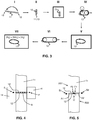
- Figure 4 illustrates the known process step II of strip welding from the overall manufacturing method of the drive belt carrier ring 13 in more detail, however not to scale.
- the strip 11 to be welded is enclosed widthwise, i.e. axial direction, between two weld-end abutments 14 at the location where the said distal ends 12 of the strip 11 meet after it has been bend into an approximately circular shape.
- a welding energy source such as a plasma arc or laser beam is started at a position S at a first one of the weld-end abutments 14 and is then moved in axial direction at a predetermined velocity over the strip 11 towards and finally across the respective other one of the abutments 14 until it reaches an final position F where it is switched off.
- a welding energy source such as a plasma arc or laser beam
- Such movement of the plasma arc or laser beam relative to the strip 11 and the abutments 14 is indicated in figure 4 by the dashed arrow A.
- the velocity and intensity of the plasma arc or laser beam are chosen such that a small part of the material of the strip 11 at either distal end 12 thereof melts and forms a single melt pool that solidifies after the plasma arc or laser beam has passed.
- the abutments 14 are provided to prevent that an axial indentation is formed in the (welded) carrier ring 13 at the position of the weld, i.e. to provide a surface for the melted strip material to adhere to in the axial direction.
- Figure 5 illustrates a novel way of carrying out the process step II of strip welding that does favorably not require the use of the known weld-end abutments 14.
- the actual welding together of the distal ends 12 of the strip 11 is realized in two phases that are respectively indicated in figure 5 by the dashed arrows A1 and A2.
- the plasma-arc or laser beam is switched on at a starting position S1 beyond a first axial side AS1 of the strip 11 and is then moved in the axial direction relative to the strip 11 to a finishing position F1 inside the strip, i.e.
- the plasma-arc or laser beam is switched on at a starting position S2 beyond the other, i.e. second axial side AS2 of the strip 11 opposite the said first axial side AS1 thereof and is then moved in the axial direction relative to the strip 11 to a second finishing position F2 in-between the axial sides AS1, AS2 of the strip 11, where the plasma-arc or laser beam is switched off again and the welding stops.
- a, preferably small, overlap O is preferably provided between the first and second phase of the welding process.
- a weld is formed between the distal ends 12 of the strip 11 in two, mutually overlapping weld parts that each start from a respective axial side AS1; AS2 of the strip 11 and extend towards the respectively opposite axial side AS1; AS2 of the strip 11 to a position beyond the axial middle of the strip 11.
Description
- This disclosure relates to a method for forming a ring from steel basic material that is destined to function as a carrier of transverse elements in a closed-loop drive belt for a continuously variable transmission, comprising the following steps:
- providing a strip of basic material with an initial thickness of about 0.4 mm;
- bending the strip into a circular or ring shape, whereby distal ends of the strip are touching, or at least facing each other;
- fixing these distal ends of the strip to each other by welding to form the steel carrier ring; and
- subjecting the steel carrier ring to a rolling process in circumference direction, whereby its thickness is reduced to less than 0.2 mm.
- A method according to the preamble of
claim 1 is known from, for instance, the international patent application publicationWO2009/ 132689-A1 . This document also discloses the preamble ofproduct claim 2. - A drive belt for a continuously variable transmission is generally known. Usually, such a drive belt comprises two sets of endless, i.e. closed-loop rings that carry a multitude of transverse elements of the drive belt, which transverse elements are arranged in an essentially contiguous row along the entire circumference thereof. These carrier rings of the drive belt are relatively flat, i.e. the radial distance between an inner circumference and an outer circumference of the carrier rings is relatively small with respect to the dimension in an axial direction.
- In a continuously variable transmission, the drive belt is disposed between two cooperating pulleys where between a continuously variable speed ratio is realized. During operation, the drive belt transmits a torque from one of the pulleys to the other one pulley, a/o by the transverse elements thereof pushing each other from the said one pulley to the said other one pulley.
- During operation of the continuously variable transmission, the carrier rings of the drive belt are exposed to bending and pulling forces. The bending forces are substantially determined by the thickness of the carrier rings and the extent to which ring portions are bent at the moments that they are present in the pulleys. The pulling forces are substantially determined by the tensile force with which the drive belt is suspended between both pulleys.
- As a consequence of the said bending and pulling forces, metal fatigue of a carrier ring will play a role in a possible failure of the drive belt. Metal fatigue is related to the type and the quality of the used steel. For example, as a consequence of irregularities in the material, hair cracks may occur. Normally, such hair cracks will form at a location where the tension stress is highest. For the present carrier rings that are repeatedly bend such tension stress will normally be highest at or near its surface, a/o at or near the axial sides of the carrier ring. Thus, for providing the carrier rings with optimal fatigue properties and, hence, also the drive belt, it is important to manufacture these with a high surface quality, i.e. with an ultimately smooth outer surface that is free from defects.
- In the manufacture of the carrier ring, a basic material having the required material properties for drive belt application of the carrier ring is provided in, for instance, a coiled-up sheet form. From this basic material a strip is cut with length, width and thickness dimensions that are adapted to (obtain) the final carrier ring of required dimensions. The distal ends of the strip, as seen in the longitudinal direction thereof, are placed opposite one another and are fixed to one another by means of a welding process to form a continuous carrier ring. Typically, plasma-arc welding or laser welding is applied for this purpose, wherein a plasma arc or laser beam is passed from one axial side of the strip to the other one side thereof. The intensity of the plasma-arc or laser beam is set to melt a small part of both the said distal ends of the strip, which melted strip parts solidify into together as one once the plasma arc or laser beam has passed. Furthermore, the manufacture of the final carrier ring for the present drive belt application thereof, is known to include several more processes such as rolling, hardening and nitriding.
- It is known from the
PCT patent publication WO2007/073158-A1 WO2007/073158-A1 such indentation should be avoided, at least in the drive belt application of the carrier ring. And, to that end,WO2007/073158-A1 , proposes to place an abutment against the axial sides of the strip to be welded at the location of the weld, i.e. of the said distal ends thereof. - According to the present disclosure and in contrast with
WO2007/073158-A1 , it was found that the said indentation is not necessarily formed to an equal extent on both axial sides of the carrier ring. In fact applicant observed that the indentation is considerably larger on the axial side of the carrier ring where the welding process ends, i.e. where the plasma-arc or laser beam passes from the strip into the surroundings to complete the weld, as compared to the indentation formed on the opposite axial side of the carrier ring where the welding process was started, i.e. where the plasma-arc or laser beam first enters from the surroundings to in-between the distal ends of the strip. - Based on the above observation, the present disclosure proposes to provide the weld in two phases, wherein, in a first phase of the welding process, the welding is started at a first axial side of the strip and is then continued towards the opposite axial side of the strip, however only to within the axial extent of the strip, where it is stopped, and wherein, in a second phase of the welding process, the welding is started at the opposite, i.e. second axial side of the strip and is then continued towards the first axial side of the strip, however, again only to within the axial extent of the strip.
- In order to avoid having to complete the overall weld in a third phase of the welding process in-between the two positions of the respective phases where the welding is stopped, the welding in the second phase of the welding process is stopped only at a position that lies in the axial direction beyond the position where the welding was stopped in the first phase thereof. Or, in other words, a weld (part) formed in the said second phase of the welding process partly overlaps with the weld (part) formed in the said first phase thereof.
- The above-described basic features of the present disclosure will now be elucidated by way of example with reference to the accompanying figures.
-
Figure 1 is a schematic illustration of a known drive belt and of a transmission incorporating such known belt. -
Figure 2 is a schematic illustration of a part of the known drive belt, which includes two sets of a number of flexible steel carrier rings, as well as a plurality of transverse members. -
Figure 3 figuratively represents a known manufacturing method of the drive belt carrier ring. -
Figure 4 illustrates the known setup of the process step of strip welding from the overall manufacturing method of the drive belt carrier ring. -
Figure 5 illustrates a novel setup of the process step of strip welding. -
Figure 1 shows schematically a continuously variable transmission (CVT) with adrive belt 3 wrapped around twopulleys pulley conical pulley discs disc 4 is axially moveable along arespective pulley shaft drive belt 3 is wrapped around thepulleys pulley pulley disc 4 thereof an axially oriented clamping force directed towards the respectiveother pulley disc 5 thereof, such that thebelt 3 can be clamped between thesediscs pulley 2 and the rotational speed of the drivingpulley 1 is determined thereby. This CVT is known per se, in particular from its application in automobiles. - An example of a known
drive belt 3 is shown in more detailfigure 2 in a section thereof. Thedrive belt 3 is made up of twosets 31 of mutually nested, flat andflexible steel rings 13 that carry a plurality oftransverse members 30. Thetransverse members 30 are arranged in mutual succession along the circumference of thering sets 31, in such manner that they can slide relative to and in the circumference direction of thering sets 31. - The
transverse segments 30 take-up the said clamping force, such when an input torque T is exerted on the so-calleddriving pulley 1, friction between thediscs belt 3, causes a rotation of thedriving pulley 1 to be transferred to the so-called drivenpulley 2 via the likewise rotatingdrive belt 3. - During operation in the CVT the
drive belt 3 and in particular thecarrier rings 13 thereof are subjected to a cyclically varying tensile and bending stresses, i.e. a fatigue load. Typically the resistance against metal fatigue, i.e. the fatigue strength of thecarrier rings 13, thus determines the functional life span of thedrive belt 3. Therefore, it has been a long standing and general development aim to optimize the fatigue strength of thecarrier ring 13 at a minimum combined material and processing cost. -
Figure 3 illustrates a relevant part of the known manufacturing method for thecarrier rings 13 to be applied in thering sets 31 of thedrive belt 3, as it is typically applied in the art. The separate process steps of the known manufacturing method are indicated by way of Roman numerals. - In a first process step I a
strip 11 of a maraging steel basic material having a thickness of around 0.4 mm, is bend into a circular shape with the distal ends of the strip being placed against one another. In a second process step II thedistal ends 12 of thestrip 11 are welded together to form acarrier ring 13, typically by means of a plasma-arc welding process. In a third step III, thecarrier ring 13 is annealed to remove the heat affected zone resulting from the welding process step II. Thereafter, in a fourth process step IV, thecarrier ring 13 is rolled to reduce the thickness thereof to, typically, less than 0.2 mm, e.g. 0.185 mm, while being elongated. Thecarrier ring 13 is subjected to a further, i.e. carrier ring annealing process step V for removing the work hardening effect of the previous rolling process step IV by recovery and re-crystallization of the ring material. Thereafter, in a sixth process step VI, thecarrier ring 13 is calibrated by mounting it around two rotating rollers and stretching it to a predefined circumference length by forcing the said rollers apart. In this sixth process step VI, also internal stresses are imposed on thecarrier ring 13. Finally, thecarrier ring 13 is heat-treated in a seventh process step VII of combined ageing or bulk precipitation hardening and nitriding or case hardening. More in particular, such combined heat-treatment involves keeping thecarrier ring 13 in an oven chamber containing a controlled gas atmosphere that comprises ammonia, nitrogen and hydrogen gas. By this heat treatment process VII both the wear resistance and the fatigue strength of the ring material is increased remarkably. -
Figure 4 illustrates the known process step II of strip welding from the overall manufacturing method of the drivebelt carrier ring 13 in more detail, however not to scale. Infigure 4 thestrip 11 to be welded is enclosed widthwise, i.e. axial direction, between two weld-end abutments 14 at the location where the said distal ends 12 of thestrip 11 meet after it has been bend into an approximately circular shape. - In the actual welding together of the distal ends 12 of the
strip 11, a welding energy source such as a plasma arc or laser beam is started at a position S at a first one of the weld-end abutments 14 and is then moved in axial direction at a predetermined velocity over thestrip 11 towards and finally across the respective other one of theabutments 14 until it reaches an final position F where it is switched off. Such movement of the plasma arc or laser beam relative to thestrip 11 and theabutments 14 is indicated infigure 4 by the dashed arrow A. The velocity and intensity of the plasma arc or laser beam are chosen such that a small part of the material of thestrip 11 at eitherdistal end 12 thereof melts and forms a single melt pool that solidifies after the plasma arc or laser beam has passed. Theabutments 14 are provided to prevent that an axial indentation is formed in the (welded)carrier ring 13 at the position of the weld, i.e. to provide a surface for the melted strip material to adhere to in the axial direction. -
Figure 5 illustrates a novel way of carrying out the process step II of strip welding that does favorably not require the use of the known weld-end abutments 14. According to the present disclosure, the actual welding together of the distal ends 12 of thestrip 11 is realized in two phases that are respectively indicated infigure 5 by the dashed arrows A1 and A2. In a first phase of the welding process, indicated by the arrow A1, the plasma-arc or laser beam is switched on at a starting position S1 beyond a first axial side AS1 of thestrip 11 and is then moved in the axial direction relative to thestrip 11 to a finishing position F1 inside the strip, i.e. to a first finishing position F1 in-between the axial sides AS1, AS2 thereof, where the plasma-arc or laser beam is switched off and the welding stops. Thereafter, in a second phase of the welding process, indicated by the arrow A2, the plasma-arc or laser beam is switched on at a starting position S2 beyond the other, i.e. second axial side AS2 of thestrip 11 opposite the said first axial side AS1 thereof and is then moved in the axial direction relative to thestrip 11 to a second finishing position F2 in-between the axial sides AS1, AS2 of thestrip 11, where the plasma-arc or laser beam is switched off again and the welding stops. - As is also illustrated in
figure 5 , a, preferably small, overlap O is preferably provided between the first and second phase of the welding process. Thus, in other words, in the process step II of strip welding, a weld is formed between the distal ends 12 of thestrip 11 in two, mutually overlapping weld parts that each start from a respective axial side AS1; AS2 of thestrip 11 and extend towards the respectively opposite axial side AS1; AS2 of thestrip 11 to a position beyond the axial middle of thestrip 11.
Claims (2)
- Method for forming a steel ring (13) for use as a carrier ring (13) in a drive belt (3) for a continuously variable transmission with two pulleys (1, 2) and the drive belt (3) and including the steps of:- providing a strip (11) of basic material with an initial thickness of about 0.4 mm;- bending the strip (11) into a circular or ring shape, whereby distal ends (12) of the strip (11) are touching, or at least facing each other;- fixing the distal ends (12) of the strip (11) to each other by welding to form the steel ring (13),characterised in that the welding of the strip (11) is carried out as or in a laser or a plasma-arc welding process in the following two phases:- a first phase wherein the distal ends (12) of the strip (11) are welded together from a fist starting position (S1) beyond a first axial side (AS1) of the strip (11) to a first finishing position (F1) located within the width of the strip (11) and- a second phase wherein the distal ends (12) of the strip (11) are welded together from a second starting position (S2) beyond a second, opposite axial side (AS2) of the strip (11) to a second finishing position (F2) located within the width of the strip (11) in-between the said first finishing position (F1) and the said first axial side (AS1) of the strip (11); and, after welding, of- subjecting the steel ring (13) to a rolling process in circumference direction, whereby the thickness thereof is reduced to less than 0.2 mm.
- Drive belt (3) with transverse elements (30) and at least one ring set (31) whereon the transverse elements (30) are mounted and which ring set (31) is composed of a number of mutually, radially stacked carrier rings (13) characterised in that the rings are formed with the method according to the preceding claim.
Applications Claiming Priority (1)
| Application Number | Priority Date | Filing Date | Title |
|---|---|---|---|
| NL1040574A NL1040574C2 (en) | 2013-12-24 | 2013-12-24 | Method for forming a carrier ring suitable for use in a drive belt for a continuously variable transmission. |
Publications (2)
| Publication Number | Publication Date |
|---|---|
| EP2889104A1 EP2889104A1 (en) | 2015-07-01 |
| EP2889104B1 true EP2889104B1 (en) | 2020-07-08 |
Family
ID=50190631
Family Applications (1)
| Application Number | Title | Priority Date | Filing Date |
|---|---|---|---|
| EP14197843.7A Active EP2889104B1 (en) | 2013-12-24 | 2014-12-15 | Method for forming a carrier ring suitable for use in a drive belt for a continuously variable transmission |
Country Status (3)
| Country | Link |
|---|---|
| EP (1) | EP2889104B1 (en) |
| JP (1) | JP2015120200A (en) |
| NL (1) | NL1040574C2 (en) |
Families Citing this family (3)
| Publication number | Priority date | Publication date | Assignee | Title |
|---|---|---|---|---|
| DE102016103571A1 (en) * | 2016-02-29 | 2017-08-31 | Oetiker Schweiz Ag | Method of making a welded ring |
| CN110494247B (en) * | 2017-03-09 | 2022-01-11 | 欧梯克瑞士公司 | Method for producing solder ring |
| JP2019177403A (en) | 2018-03-30 | 2019-10-17 | トヨタ自動車株式会社 | Manufacturing method of endless metal ring |
Family Cites Families (5)
| Publication number | Priority date | Publication date | Assignee | Title |
|---|---|---|---|---|
| JPS5825892A (en) * | 1981-08-07 | 1983-02-16 | Hitachi Zosen Corp | Preventing method for terminal cracking in automatic one side welding |
| JP4173976B2 (en) * | 2002-06-20 | 2008-10-29 | 本田技研工業株式会社 | Manufacturing method of hoop for automatic transmission of automobile |
| JP4784217B2 (en) * | 2005-09-07 | 2011-10-05 | 住友金属工業株式会社 | Continuously variable transmission belt, stainless steel plate for the belt, and manufacturing method thereof |
| NL1030704C2 (en) * | 2005-12-19 | 2007-06-20 | Bosch Gmbh Robert | Method for forming a support ring of a push belt for a continuously variable transmission. |
| JP2011518672A (en) * | 2008-04-28 | 2011-06-30 | ローベルト ボツシユ ゲゼルシヤフト ミツト ベシユレンクテル ハフツング | Method for manufacturing ring component of drive belt |
-
2013
- 2013-12-24 NL NL1040574A patent/NL1040574C2/en not_active IP Right Cessation
-
2014
- 2014-12-15 EP EP14197843.7A patent/EP2889104B1/en active Active
- 2014-12-24 JP JP2014260544A patent/JP2015120200A/en active Pending
Non-Patent Citations (1)
| Title |
|---|
| None * |
Also Published As
| Publication number | Publication date |
|---|---|
| NL1040574C2 (en) | 2015-06-26 |
| EP2889104A1 (en) | 2015-07-01 |
| JP2015120200A (en) | 2015-07-02 |
Similar Documents
| Publication | Publication Date | Title |
|---|---|---|
| EP2889104B1 (en) | Method for forming a carrier ring suitable for use in a drive belt for a continuously variable transmission | |
| EP2891819A1 (en) | Method for manufacturing endless metal belt, endless metal belt, and belt-type continuously variable transmission | |
| JP6556143B2 (en) | Method of manufacturing a carrier ring suitable for use in a drive belt for a continuously variable transmission | |
| NL1043109B1 (en) | Method for manufacturing a metal ring for a ring set of a drive belt for a continuously variable transmission | |
| EP3234211B1 (en) | Method for producing a flexible steel ring for a drive belt for a continuously variable transmission | |
| JP2011185300A (en) | Method for manufacturing of laminated ring | |
| WO2009056169A1 (en) | Drive belt ring component and manufacturing method therefor | |
| EP2486303B1 (en) | Drive belt provided with a laminated set of steel rings | |
| NL1037583C2 (en) | Drive belt provided with a steel ring. | |
| EP3374662B1 (en) | Metal ring component of a drive belt for a continuously variable transmission | |
| WO2018221646A1 (en) | Endless ring production method | |
| JP2011518672A (en) | Method for manufacturing ring component of drive belt | |
| JP5712743B2 (en) | Manufacturing apparatus and manufacturing method of thin plate-like endless metal ring | |
| JP5621685B2 (en) | Manufacturing method of thin plate-like endless metal ring | |
| CN105849436B (en) | The method of the flexible steel ring and this ring of manufacture equipped with nanocrystal surface layer of transmission belt for stepless transmission | |
| NL1040571C2 (en) | Metal ring component for a drive belt for a continuously variable transmission. | |
| JP5776455B2 (en) | Endless metal ring manufacturing apparatus and manufacturing method | |
| JP4923287B2 (en) | Metal ring circumference corrector | |
| JP5949478B2 (en) | Laminated ring and laminated ring manufacturing method | |
| JP5057271B2 (en) | Metal ring manufacturing method | |
| JP2017509788A (en) | Drive belt metal ring component manufacturing method and metal ring manufactured according to the manufacturing method | |
| JP5124845B2 (en) | Metal ring circumference correction method | |
| WO2007073158A1 (en) | Method for forming a carrying ring of a push belt for a continuously variable transmission | |
| JP2014176900A (en) | Method of manufacturing ring component of drive belt | |
| WO2018019435A1 (en) | Flexible steel ring made from maraging steel and provided with a nitrided surface layer |
Legal Events
| Date | Code | Title | Description |
|---|---|---|---|
| PUAI | Public reference made under article 153(3) epc to a published international application that has entered the european phase |
Free format text: ORIGINAL CODE: 0009012 |
|
| 17P | Request for examination filed |
Effective date: 20141215 |
|
| AK | Designated contracting states |
Kind code of ref document: A1 Designated state(s): AL AT BE BG CH CY CZ DE DK EE ES FI FR GB GR HR HU IE IS IT LI LT LU LV MC MK MT NL NO PL PT RO RS SE SI SK SM TR |
|
| AX | Request for extension of the european patent |
Extension state: BA ME |
|
| R17P | Request for examination filed (corrected) |
Effective date: 20160104 |
|
| RBV | Designated contracting states (corrected) |
Designated state(s): AL AT BE BG CH CY CZ DE DK EE ES FI FR GB GR HR HU IE IS IT LI LT LU LV MC MK MT NL NO PL PT RO RS SE SI SK SM TR |
|
| GRAP | Despatch of communication of intention to grant a patent |
Free format text: ORIGINAL CODE: EPIDOSNIGR1 |
|
| STAA | Information on the status of an ep patent application or granted ep patent |
Free format text: STATUS: GRANT OF PATENT IS INTENDED |
|
| INTG | Intention to grant announced |
Effective date: 20200204 |
|
| RIN1 | Information on inventor provided before grant (corrected) |
Inventor name: BIRNESSER, ANDREAS Inventor name: CORNELISSEN, RONALD Inventor name: BRANDSMA, ARJEN Inventor name: RAMSAYER, REINER |
|
| RAP1 | Party data changed (applicant data changed or rights of an application transferred) |
Owner name: ROBERT BOSCH GMBH |
|
| GRAS | Grant fee paid |
Free format text: ORIGINAL CODE: EPIDOSNIGR3 |
|
| GRAA | (expected) grant |
Free format text: ORIGINAL CODE: 0009210 |
|
| STAA | Information on the status of an ep patent application or granted ep patent |
Free format text: STATUS: THE PATENT HAS BEEN GRANTED |
|
| AK | Designated contracting states |
Kind code of ref document: B1 Designated state(s): AL AT BE BG CH CY CZ DE DK EE ES FI FR GB GR HR HU IE IS IT LI LT LU LV MC MK MT NL NO PL PT RO RS SE SI SK SM TR |
|
| REG | Reference to a national code |
Ref country code: AT Ref legal event code: REF Ref document number: 1287936 Country of ref document: AT Kind code of ref document: T Effective date: 20200715 Ref country code: CH Ref legal event code: EP |
|
| REG | Reference to a national code |
Ref country code: DE Ref legal event code: R096 Ref document number: 602014067429 Country of ref document: DE |
|
| REG | Reference to a national code |
Ref country code: IE Ref legal event code: FG4D |
|
| REG | Reference to a national code |
Ref country code: NL Ref legal event code: FP |
|
| REG | Reference to a national code |
Ref country code: LT Ref legal event code: MG4D |
|
| REG | Reference to a national code |
Ref country code: AT Ref legal event code: MK05 Ref document number: 1287936 Country of ref document: AT Kind code of ref document: T Effective date: 20200708 |
|
| PG25 | Lapsed in a contracting state [announced via postgrant information from national office to epo] |
Ref country code: PT Free format text: LAPSE BECAUSE OF FAILURE TO SUBMIT A TRANSLATION OF THE DESCRIPTION OR TO PAY THE FEE WITHIN THE PRESCRIBED TIME-LIMIT Effective date: 20201109 Ref country code: AT Free format text: LAPSE BECAUSE OF FAILURE TO SUBMIT A TRANSLATION OF THE DESCRIPTION OR TO PAY THE FEE WITHIN THE PRESCRIBED TIME-LIMIT Effective date: 20200708 Ref country code: BG Free format text: LAPSE BECAUSE OF FAILURE TO SUBMIT A TRANSLATION OF THE DESCRIPTION OR TO PAY THE FEE WITHIN THE PRESCRIBED TIME-LIMIT Effective date: 20201008 Ref country code: HR Free format text: LAPSE BECAUSE OF FAILURE TO SUBMIT A TRANSLATION OF THE DESCRIPTION OR TO PAY THE FEE WITHIN THE PRESCRIBED TIME-LIMIT Effective date: 20200708 Ref country code: FI Free format text: LAPSE BECAUSE OF FAILURE TO SUBMIT A TRANSLATION OF THE DESCRIPTION OR TO PAY THE FEE WITHIN THE PRESCRIBED TIME-LIMIT Effective date: 20200708 Ref country code: LT Free format text: LAPSE BECAUSE OF FAILURE TO SUBMIT A TRANSLATION OF THE DESCRIPTION OR TO PAY THE FEE WITHIN THE PRESCRIBED TIME-LIMIT Effective date: 20200708 Ref country code: SE Free format text: LAPSE BECAUSE OF FAILURE TO SUBMIT A TRANSLATION OF THE DESCRIPTION OR TO PAY THE FEE WITHIN THE PRESCRIBED TIME-LIMIT Effective date: 20200708 Ref country code: NO Free format text: LAPSE BECAUSE OF FAILURE TO SUBMIT A TRANSLATION OF THE DESCRIPTION OR TO PAY THE FEE WITHIN THE PRESCRIBED TIME-LIMIT Effective date: 20201008 Ref country code: GR Free format text: LAPSE BECAUSE OF FAILURE TO SUBMIT A TRANSLATION OF THE DESCRIPTION OR TO PAY THE FEE WITHIN THE PRESCRIBED TIME-LIMIT Effective date: 20201009 Ref country code: ES Free format text: LAPSE BECAUSE OF FAILURE TO SUBMIT A TRANSLATION OF THE DESCRIPTION OR TO PAY THE FEE WITHIN THE PRESCRIBED TIME-LIMIT Effective date: 20200708 |
|
| PG25 | Lapsed in a contracting state [announced via postgrant information from national office to epo] |
Ref country code: IS Free format text: LAPSE BECAUSE OF FAILURE TO SUBMIT A TRANSLATION OF THE DESCRIPTION OR TO PAY THE FEE WITHIN THE PRESCRIBED TIME-LIMIT Effective date: 20201108 Ref country code: LV Free format text: LAPSE BECAUSE OF FAILURE TO SUBMIT A TRANSLATION OF THE DESCRIPTION OR TO PAY THE FEE WITHIN THE PRESCRIBED TIME-LIMIT Effective date: 20200708 Ref country code: RS Free format text: LAPSE BECAUSE OF FAILURE TO SUBMIT A TRANSLATION OF THE DESCRIPTION OR TO PAY THE FEE WITHIN THE PRESCRIBED TIME-LIMIT Effective date: 20200708 Ref country code: PL Free format text: LAPSE BECAUSE OF FAILURE TO SUBMIT A TRANSLATION OF THE DESCRIPTION OR TO PAY THE FEE WITHIN THE PRESCRIBED TIME-LIMIT Effective date: 20200708 |
|
| REG | Reference to a national code |
Ref country code: DE Ref legal event code: R097 Ref document number: 602014067429 Country of ref document: DE |
|
| PG25 | Lapsed in a contracting state [announced via postgrant information from national office to epo] |
Ref country code: RO Free format text: LAPSE BECAUSE OF FAILURE TO SUBMIT A TRANSLATION OF THE DESCRIPTION OR TO PAY THE FEE WITHIN THE PRESCRIBED TIME-LIMIT Effective date: 20200708 Ref country code: SM Free format text: LAPSE BECAUSE OF FAILURE TO SUBMIT A TRANSLATION OF THE DESCRIPTION OR TO PAY THE FEE WITHIN THE PRESCRIBED TIME-LIMIT Effective date: 20200708 Ref country code: EE Free format text: LAPSE BECAUSE OF FAILURE TO SUBMIT A TRANSLATION OF THE DESCRIPTION OR TO PAY THE FEE WITHIN THE PRESCRIBED TIME-LIMIT Effective date: 20200708 Ref country code: CZ Free format text: LAPSE BECAUSE OF FAILURE TO SUBMIT A TRANSLATION OF THE DESCRIPTION OR TO PAY THE FEE WITHIN THE PRESCRIBED TIME-LIMIT Effective date: 20200708 Ref country code: DK Free format text: LAPSE BECAUSE OF FAILURE TO SUBMIT A TRANSLATION OF THE DESCRIPTION OR TO PAY THE FEE WITHIN THE PRESCRIBED TIME-LIMIT Effective date: 20200708 Ref country code: IT Free format text: LAPSE BECAUSE OF FAILURE TO SUBMIT A TRANSLATION OF THE DESCRIPTION OR TO PAY THE FEE WITHIN THE PRESCRIBED TIME-LIMIT Effective date: 20200708 |
|
| PLBE | No opposition filed within time limit |
Free format text: ORIGINAL CODE: 0009261 |
|
| STAA | Information on the status of an ep patent application or granted ep patent |
Free format text: STATUS: NO OPPOSITION FILED WITHIN TIME LIMIT |
|
| PG25 | Lapsed in a contracting state [announced via postgrant information from national office to epo] |
Ref country code: AL Free format text: LAPSE BECAUSE OF FAILURE TO SUBMIT A TRANSLATION OF THE DESCRIPTION OR TO PAY THE FEE WITHIN THE PRESCRIBED TIME-LIMIT Effective date: 20200708 |
|
| 26N | No opposition filed |
Effective date: 20210409 |
|
| PG25 | Lapsed in a contracting state [announced via postgrant information from national office to epo] |
Ref country code: SK Free format text: LAPSE BECAUSE OF FAILURE TO SUBMIT A TRANSLATION OF THE DESCRIPTION OR TO PAY THE FEE WITHIN THE PRESCRIBED TIME-LIMIT Effective date: 20200708 |
|
| REG | Reference to a national code |
Ref country code: CH Ref legal event code: PL |
|
| GBPC | Gb: european patent ceased through non-payment of renewal fee |
Effective date: 20201215 |
|
| PG25 | Lapsed in a contracting state [announced via postgrant information from national office to epo] |
Ref country code: SI Free format text: LAPSE BECAUSE OF FAILURE TO SUBMIT A TRANSLATION OF THE DESCRIPTION OR TO PAY THE FEE WITHIN THE PRESCRIBED TIME-LIMIT Effective date: 20200708 Ref country code: MC Free format text: LAPSE BECAUSE OF FAILURE TO SUBMIT A TRANSLATION OF THE DESCRIPTION OR TO PAY THE FEE WITHIN THE PRESCRIBED TIME-LIMIT Effective date: 20200708 |
|
| REG | Reference to a national code |
Ref country code: BE Ref legal event code: MM Effective date: 20201231 |
|
| PG25 | Lapsed in a contracting state [announced via postgrant information from national office to epo] |
Ref country code: IE Free format text: LAPSE BECAUSE OF NON-PAYMENT OF DUE FEES Effective date: 20201215 Ref country code: LU Free format text: LAPSE BECAUSE OF NON-PAYMENT OF DUE FEES Effective date: 20201215 Ref country code: FR Free format text: LAPSE BECAUSE OF NON-PAYMENT OF DUE FEES Effective date: 20201231 |
|
| PG25 | Lapsed in a contracting state [announced via postgrant information from national office to epo] |
Ref country code: LI Free format text: LAPSE BECAUSE OF NON-PAYMENT OF DUE FEES Effective date: 20201231 Ref country code: CH Free format text: LAPSE BECAUSE OF NON-PAYMENT OF DUE FEES Effective date: 20201231 Ref country code: GB Free format text: LAPSE BECAUSE OF NON-PAYMENT OF DUE FEES Effective date: 20201215 |
|
| PG25 | Lapsed in a contracting state [announced via postgrant information from national office to epo] |
Ref country code: IS Free format text: LAPSE BECAUSE OF FAILURE TO SUBMIT A TRANSLATION OF THE DESCRIPTION OR TO PAY THE FEE WITHIN THE PRESCRIBED TIME-LIMIT Effective date: 20201108 Ref country code: TR Free format text: LAPSE BECAUSE OF FAILURE TO SUBMIT A TRANSLATION OF THE DESCRIPTION OR TO PAY THE FEE WITHIN THE PRESCRIBED TIME-LIMIT Effective date: 20200708 Ref country code: MT Free format text: LAPSE BECAUSE OF FAILURE TO SUBMIT A TRANSLATION OF THE DESCRIPTION OR TO PAY THE FEE WITHIN THE PRESCRIBED TIME-LIMIT Effective date: 20200708 Ref country code: CY Free format text: LAPSE BECAUSE OF FAILURE TO SUBMIT A TRANSLATION OF THE DESCRIPTION OR TO PAY THE FEE WITHIN THE PRESCRIBED TIME-LIMIT Effective date: 20200708 |
|
| PG25 | Lapsed in a contracting state [announced via postgrant information from national office to epo] |
Ref country code: MK Free format text: LAPSE BECAUSE OF FAILURE TO SUBMIT A TRANSLATION OF THE DESCRIPTION OR TO PAY THE FEE WITHIN THE PRESCRIBED TIME-LIMIT Effective date: 20200708 |
|
| PG25 | Lapsed in a contracting state [announced via postgrant information from national office to epo] |
Ref country code: BE Free format text: LAPSE BECAUSE OF NON-PAYMENT OF DUE FEES Effective date: 20201231 |
|
| PGFP | Annual fee paid to national office [announced via postgrant information from national office to epo] |
Ref country code: NL Payment date: 20221220 Year of fee payment: 9 |
|
| PGFP | Annual fee paid to national office [announced via postgrant information from national office to epo] |
Ref country code: DE Payment date: 20230223 Year of fee payment: 9 |