EP3015541A1 - Work chamber - Google Patents
Work chamber Download PDFInfo
- Publication number
- EP3015541A1 EP3015541A1 EP14849470.1A EP14849470A EP3015541A1 EP 3015541 A1 EP3015541 A1 EP 3015541A1 EP 14849470 A EP14849470 A EP 14849470A EP 3015541 A1 EP3015541 A1 EP 3015541A1
- Authority
- EP
- European Patent Office
- Prior art keywords
- work space
- louver
- work
- glove box
- supply
- Prior art date
- Legal status (The legal status is an assumption and is not a legal conclusion. Google has not performed a legal analysis and makes no representation as to the accuracy of the status listed.)
- Withdrawn
Links
Images


Classifications
-
- C—CHEMISTRY; METALLURGY
- C12—BIOCHEMISTRY; BEER; SPIRITS; WINE; VINEGAR; MICROBIOLOGY; ENZYMOLOGY; MUTATION OR GENETIC ENGINEERING
- C12M—APPARATUS FOR ENZYMOLOGY OR MICROBIOLOGY; APPARATUS FOR CULTURING MICROORGANISMS FOR PRODUCING BIOMASS, FOR GROWING CELLS OR FOR OBTAINING FERMENTATION OR METABOLIC PRODUCTS, i.e. BIOREACTORS OR FERMENTERS
- C12M37/00—Means for sterilizing, maintaining sterile conditions or avoiding chemical or biological contamination
- C12M37/02—Filters
-
- B—PERFORMING OPERATIONS; TRANSPORTING
- B01—PHYSICAL OR CHEMICAL PROCESSES OR APPARATUS IN GENERAL
- B01L—CHEMICAL OR PHYSICAL LABORATORY APPARATUS FOR GENERAL USE
- B01L1/00—Enclosures; Chambers
- B01L1/04—Dust-free rooms or enclosures
-
- B—PERFORMING OPERATIONS; TRANSPORTING
- B25—HAND TOOLS; PORTABLE POWER-DRIVEN TOOLS; MANIPULATORS
- B25J—MANIPULATORS; CHAMBERS PROVIDED WITH MANIPULATION DEVICES
- B25J21/00—Chambers provided with manipulation devices
- B25J21/02—Glove-boxes, i.e. chambers in which manipulations are performed by the human hands in gloves built into the chamber walls; Gloves therefor
-
- C—CHEMISTRY; METALLURGY
- C12—BIOCHEMISTRY; BEER; SPIRITS; WINE; VINEGAR; MICROBIOLOGY; ENZYMOLOGY; MUTATION OR GENETIC ENGINEERING
- C12M—APPARATUS FOR ENZYMOLOGY OR MICROBIOLOGY; APPARATUS FOR CULTURING MICROORGANISMS FOR PRODUCING BIOMASS, FOR GROWING CELLS OR FOR OBTAINING FERMENTATION OR METABOLIC PRODUCTS, i.e. BIOREACTORS OR FERMENTERS
- C12M29/00—Means for introduction, extraction or recirculation of materials, e.g. pumps
- C12M29/04—Filters; Permeable or porous membranes or plates, e.g. dialysis
-
- C—CHEMISTRY; METALLURGY
- C12—BIOCHEMISTRY; BEER; SPIRITS; WINE; VINEGAR; MICROBIOLOGY; ENZYMOLOGY; MUTATION OR GENETIC ENGINEERING
- C12M—APPARATUS FOR ENZYMOLOGY OR MICROBIOLOGY; APPARATUS FOR CULTURING MICROORGANISMS FOR PRODUCING BIOMASS, FOR GROWING CELLS OR FOR OBTAINING FERMENTATION OR METABOLIC PRODUCTS, i.e. BIOREACTORS OR FERMENTERS
- C12M29/00—Means for introduction, extraction or recirculation of materials, e.g. pumps
- C12M29/06—Nozzles; Sprayers; Spargers; Diffusers
-
- C—CHEMISTRY; METALLURGY
- C12—BIOCHEMISTRY; BEER; SPIRITS; WINE; VINEGAR; MICROBIOLOGY; ENZYMOLOGY; MUTATION OR GENETIC ENGINEERING
- C12M—APPARATUS FOR ENZYMOLOGY OR MICROBIOLOGY; APPARATUS FOR CULTURING MICROORGANISMS FOR PRODUCING BIOMASS, FOR GROWING CELLS OR FOR OBTAINING FERMENTATION OR METABOLIC PRODUCTS, i.e. BIOREACTORS OR FERMENTERS
- C12M31/00—Means for providing, directing, scattering or concentrating light
-
- C—CHEMISTRY; METALLURGY
- C12—BIOCHEMISTRY; BEER; SPIRITS; WINE; VINEGAR; MICROBIOLOGY; ENZYMOLOGY; MUTATION OR GENETIC ENGINEERING
- C12M—APPARATUS FOR ENZYMOLOGY OR MICROBIOLOGY; APPARATUS FOR CULTURING MICROORGANISMS FOR PRODUCING BIOMASS, FOR GROWING CELLS OR FOR OBTAINING FERMENTATION OR METABOLIC PRODUCTS, i.e. BIOREACTORS OR FERMENTERS
- C12M31/00—Means for providing, directing, scattering or concentrating light
- C12M31/02—Means for providing, directing, scattering or concentrating light located outside the reactor
-
- C—CHEMISTRY; METALLURGY
- C12—BIOCHEMISTRY; BEER; SPIRITS; WINE; VINEGAR; MICROBIOLOGY; ENZYMOLOGY; MUTATION OR GENETIC ENGINEERING
- C12M—APPARATUS FOR ENZYMOLOGY OR MICROBIOLOGY; APPARATUS FOR CULTURING MICROORGANISMS FOR PRODUCING BIOMASS, FOR GROWING CELLS OR FOR OBTAINING FERMENTATION OR METABOLIC PRODUCTS, i.e. BIOREACTORS OR FERMENTERS
- C12M37/00—Means for sterilizing, maintaining sterile conditions or avoiding chemical or biological contamination
-
- C—CHEMISTRY; METALLURGY
- C12—BIOCHEMISTRY; BEER; SPIRITS; WINE; VINEGAR; MICROBIOLOGY; ENZYMOLOGY; MUTATION OR GENETIC ENGINEERING
- C12M—APPARATUS FOR ENZYMOLOGY OR MICROBIOLOGY; APPARATUS FOR CULTURING MICROORGANISMS FOR PRODUCING BIOMASS, FOR GROWING CELLS OR FOR OBTAINING FERMENTATION OR METABOLIC PRODUCTS, i.e. BIOREACTORS OR FERMENTERS
- C12M41/00—Means for regulation, monitoring, measurement or control, e.g. flow regulation
- C12M41/12—Means for regulation, monitoring, measurement or control, e.g. flow regulation of temperature
- C12M41/14—Incubators; Climatic chambers
-
- B—PERFORMING OPERATIONS; TRANSPORTING
- B01—PHYSICAL OR CHEMICAL PROCESSES OR APPARATUS IN GENERAL
- B01L—CHEMICAL OR PHYSICAL LABORATORY APPARATUS FOR GENERAL USE
- B01L1/00—Enclosures; Chambers
- B01L1/02—Air-pressure chambers; Air-locks therefor
- B01L1/025—Environmental chambers
Definitions
- the present disclosure relates to a working chamber, such as an isolator, a clean bench, or a cabinet, used for a regenerative medical experiment environmental device and a pharmaceutical experiment environmental device.
- a working chamber such as an isolator, a clean bench, or a cabinet, used for a regenerative medical experiment environmental device and a pharmaceutical experiment environmental device.
- Patent Literature 1 discloses an isolator that can prevent dust from being mixed into cells and the like and can prevent dust from affecting culture works such as cell manipulation. This isolator supplies gas downward from above a working chamber by an air current control means, and discharges the gas in the working chamber from discharge hole portions provided on a work plate.
- Patent Literature 1 Japanese Patent Application Laid-open Publication No. 2011-177091
- the present disclosure is to provide a working chamber that improves workability.
- a working chamber includes: a box-shaped body case including a work space in an interior thereof and an insertion portion, in a front surface thereof, to which a worker's arm is inserted; a supply unit configured to supply, into the work space, gas in an exterior of the body case through a supply filter provided at the upper front of the work space in the body case; a louver that guides gas supplied into the work space by the supply unit to a back surface side of the work space after the gas passes through the supply filter; and an illuminating means positioned lower than the louver and in front of the louver in the work space, in an upper part of the work space in the body case, at least one surface of the louver, which faces the illuminating means, being a reflection surface.
- a working chamber according to the present disclosure is effective in improving workability.
- An isolator system 100 will be described hereinafter as an example of a working chamber in an embodiment 1 with reference to Figs. 1 to 5 .
- the isolator system 100 in the embodiment 1 is a device configured to perform, for example, work for cell culture, manipulation, observation, etc., in a sterilized environment.
- sterilization means an act of killing microorganisms, cells and the like, to bring a state closer to a sterile environment.
- the Z axis is an axis along a vertical direction in which the isolator system 100 is provided in a standing manner, and a direction toward the upper side is +Z direction and a direction toward the lower side (downward) is -Z direction.
- the Y axis is an axis along a direction perpendicular to the front surface and the back surface of the isolator system 100, and a direction from the front surface, where openings for conducting work in the interior of a work space are provided, toward the back surface opposite to the front surface is -Y direction, and a direction from the back surface toward the front surface is +Y direction.
- the X axis is an axis along a direction perpendicular to the left and right side surfaces when seen from the front, and a direction from the left side surface toward the right side surface when seen from the front is +X direction, and a direction from the right side surface toward the left side surface is -X direction.
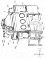
- Fig. 1 is a perspective view illustrating an isolator system 100 according to an embodiment 1.
- Fig. 2 is a perspective view illustrating the isolator system 100 when an incubator 200 is mounted thereto according to the embodiment 1.
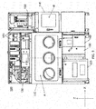
- Fig. 3 is a front view of the isolator system 100 according to the embodiment 1.
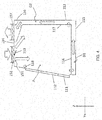
- Fig. 4 is a 4-4 cross-sectional view of a glove box 110 in Fig. 3 .
- the isolator system 100 includes : a glove box 110; a centrifuge unit 120; an observation unit 130; a sterilization unit 140; an air conditioning unit 150; a control unit 160 (see Fig. 3 ); a pass box 170; and an air conditioning unit 180.
- the incubator 200 is mounted to the side surface opposite to the side surface to which the pass box 170 is provided in the glove box 110.
- the incubator 200 includes a storage chamber (not shown) in the interior thereof.
- the storage chamber is a chamber for storing a culture, and is partitioned as a space to restrain bacterial invasion from the exterior, for example, by a rectangular parallelepiped-shaped box body.
- the storage chamber is partitioned with, for example, stainless steel plates.
- the incubator 200 is demountably configured with respect to the isolator system 100.
- culture can be controlled in each incubator 200.
- a dedicated incubator 200 can be used for each donor, thereby restraining occurrence of failures such as mix-up of culture.
- the glove box 110 includes a substantially box-shaped work space A, formed in the interior thereof, that is isolated from the surroundings to conduct work in the sterilized environment. A detailed configuration will be described later.
- the centrifuge unit 120 is provided below the glove box 110, and can be connected from the work space A.
- the centrifuge unit 120 includes, in the interior thereof, a centrifuge configured to centrifuge a sample to work with in the work space A.
- the observation unit 130 is provided below the glove box 110, and can be connected from the work space A.
- the observation unit 130 includes, in the interior thereof, an observation device configured to observe a sample to work with in the work space A.
- the observation unit 130 includes: a lifting mechanism capable of lifting and lowering the observation device provided in the interior thereof; and a handle, provided in the exterior, with which the lifting mechanism is operated. A worker operates the lifting mechanism using the handle, so that the observation device can be moved up into the work space A when the observation device is used and the observation device can be housed in the observation unit 130 when the observation unit 130 is not used.
- the sterilization unit 140 is provided below the glove box 110, to supply a sterilizing substance such as hydrogen peroxide into the glove box 110.
- the sterilization unit 140 in the present embodiment is configured to spray sterilizing mist, obtained by converting sterilizing liquid into mist, through a nozzle provided in the glove box 110, to sterilize the interior thereof.
- the air conditioning unit 150 is provided above the glove box 110, and is configured to control the air conditioning in the interior thereof.
- the air conditioning unit 150 includes a supply unit 150a and a discharge unit 150b.
- the air conditioning unit 150 is configured to supply gas into the work space A using the supply unit 150a, and discharge the gas in the work space A using the discharge unit 150b.
- control unit 160 is provided above the glove box 110 and the pass box 170, and is configured to control the operations of the devices such as the sterilization unit 140 and the air conditioning unit 150.
- the pass box 170 is provided to the side surface of the glove box 110 to allow the worker to bring a work object from the exterior into the interior of the work space A.
- a conveying space B is formed in which the work object is temporarily stored.
- the conveying space B has airtightness with respect to surrounding environment.
- An opening for moving the work object is provided to the side surface of the pass box 170 and faces an opening provided to the side surface of the glove box 110, so that the glove box 110 and the pass box 170 are fixed. In this way, the work space A and the conveying space B communicate with each other while maintaining airtightness.
- the opening of the pass box 170 has an openable/closable door installed thereto.
- the door can separate the conveying space B from the work space A while maintaining airtightness.
- the air conditioning unit 180 is provided at the upper portion of the pass box 170, and is configured to control the air conditioning in the conveying space B therein.
- Fig. 4 is a 4-4 cross-sectional view of a glove box in Fig. 3 .
- the box-shaped body case is configured with a front surface plate 111 having a plurality of front surface openings 112, which are insertion portions for worker's hands, a back surface plate 113, a top surface plate 114, a bottom surface plate 115, and left and right side surface plates.
- the glove box 110 includes, in the interior thereof: a work plate 116 on which work is conducted; and a partitioning plate 117 provided to the back surface side of the glove box.
- the box shaped work space A that is a space for conducting work is formed with the front surface plate 111, the top surface plate 114, the work plate 116, the partitioning plate 117, and the left and right side surface plates.
- the glove box 110 is a compartment that is formed with airtightness so as to restrain bacterial invasion from the exterior.
- the work plate 116, the partitioning plate 117, the bottom surface plate 115, the back surface plate 113, the top surface plate 114, and the left and right side surface plates are configured with stainless steel plates, which is easily cleaned and sterilized.
- the front surface plate 111 is openable/closable about a hinge provided an upper end thereof serving as an axis.
- Openings for mounting the pass box 170 and the incubator 200 are formed on left and right side surface plates.
- the pass box 170 is mounted to the opening on the right side surface plate of the glove box 110, and the incubator 200 is mounted to the opening on the left side surface plate thereof.
- a worker conducts work in the interior of the work space A through gloves at the time of working.
- a bottom surface duct D1 is formed between the work plate 116 and the bottom surface plate 115 as a discharge path through which the gas in the work space A is discharged. Further, a back surface duct D2 is formed between the partitioning plate 117 and the back surface plate 113 as a discharge path through which the gas in the work space A is discharged.
- the bottom surface duct D1 and the back surface duct D2 communicate with each other.
- the gas supplied from the inlet 151 flows substantially in a direction indicated by arrows in the figure, and passes through the bottom surface duct D1 and the back surface duct D2 to be discharged from the outlet 156. In this way, the gas flow can be stabilized in the work space A and contamination can be suppressed.
- the top surface plate 114 in the glove box 110 is provided with an inlet 151 and an outlet 156.
- the inlet 151 is disposed at the upper front of the work space A, and the outlet 156 is disposed at the upper rear thereof.
- the gas is supplied into the work space A from the inlet 151, and the gas in the work space A is discharged from the outlet 156.
- a particulate trap filter 152 such as an HEPA filter is mounted to the inlet 151 to secure the sterile environment in the interior, and the gas is supplied through the particulate trap filter 152 into the glove box 110.
- a particulate trap filter 157 such as the HEPA filter is mounted to the outlet 156, and the gas in the glove box 110 is discharged from the interior of the glove box 110 through the particulate trap filter 157.
- a louver 153 is provided that guides the gas supplied into the work space A by the supply unit 150a to the back surface side of the work space A, that is, to the partitioning plate 117 side, after the gas passes through the particulate trap filter 152.
- the upper portion of the louver 153 is fixed to the top surface plate 114 so as to allow the lower portion of the louver 153 to be closer to the back surface side than the upper portion thereof. In other words, the louver 153 is inclined to the back surface side from the upper portion toward the lower portion. Further, the front surface of the louver 153 is mirror-finished to be a reflection surface.
- An illuminating unit 118 is provided at the upper front of the work space A in the glove box 110 for easily conducting works by brightly illuminating the interior of the work space A, particularly, the work plate 116.
- the illuminating unit 118 is positioned lower than the louver 153 and in front of the louver 153 in the work space A.
- the illuminating unit 118 is provided to the upper front side of the work space A in a horizontal direction.
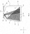
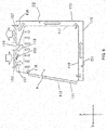
- Fig. 5 is an explanatory view showing a course of an illuminating light from the illuminating unit 118 according to the embodiment 1.
- the isolator system 100 (working chamber) includes: the box shaped glove box 110 (body case) having the work space A in the interior thereof and the front surface openings 112 (insertion portions) on the front surface thereof, to which a worker' s arms are to be inserted; the supply unit 150a (supply part) configured to supply the gas outside the glove box 110 into the work space A through the particulate trap filter 152 (supply filter) for air supply, which is provided at the upper front of the work space A in the glove box 110; the louver 153 that guides the gas supplied into the work space A by the supply unit 150a to the back surface side of the work space A after the gass passes through the particulate trap filter 152; and the illuminating unit 118 (illuminating means) positioned lower than the louver 153 and in front of the louver 153 in the work space A in the upper portion of the work space A in the glove box 110, and at least one surface of the louver 153, which faces the illuminating unit
- the isolator system 100 in the present embodiment is provided with the louver 153, and thus both suppressing contamination and illuminating the work plate 116 can be configured by one member.
- the isolator system 100 includes: the particulate trap filter 157 (discharge filter) for discharging gas, which is provided at the upper rear of the glove box 110; the discharge unit 150b (discharge part) that discharges air in the work space A to the outside through the particulate trap filter 157; and the partitioning plate 117 which is provided on the back surface side of the glove box 110 to form a ventilation passage between the back surface plate 113 of glove box 110 and the partitioning plate 117 and partition air currents into supply air and discharge air.
- the particulate trap filter 157 discharge filter
- the discharge unit 150b discharge part
- the partitioning plate 117 which is provided on the back surface side of the glove box 110 to form a ventilation passage between the back surface plate 113 of glove box 110 and the partitioning plate 117 and partition air currents into supply air and discharge air.
- the isolator system 100 can separate the air current supplied into the work space from the air current to be discharged from the work space A. This can further suppress contamination.
- the embodiment 1 has been described as an example of the technique disclosed in the present application.
- the present disclosed technique is not limited thereto, but is applicable to an embodiment in which modifications, replacements, additions, omissions and the like are made as appropriate.
- the components described in the above embodiment 1 can be combined to configure a new embodiment.
- the glove box 110 has been described as an example of the body case.
- the glove box 110 is not limited to a body case for an isolator in which work is conducted in the work space A through gloves.
- the present disclosed technique is useful also for a clean bench or a cabinet having the front surface openings 112 to which no glove is mounted.
- the body case may be the one in which gas is supplied into the work space A to adjust an environment of the work space A, in an experimental environment device in which a worker inserts his/her hand into the work space A to conduct work in the interior thereof.
- a top board facing the work plate 116 may be provided at the upper part of the work space A that is formed in the glove box 110 in the embodiment 1. In this case, it is necessary for the top board to be provided with hole portions through which the supplied gas passes.
- Fig. 6 is a cross-sectional view of a glove box 190 according to another embodiment.
- the glove box 190 shown in Fig. 6 includes a top board 119 having a plurality of hole portions.
- Fig. 7 is an explanatory view showing a course of an illuminating light from the illuminating unit 118 according to another embodiment.
- the louver 153 is disposed between the top board 119 and the particulate trap filter 152 for air supply.
- the illuminating unit 118 is disposed below the top board 119, and the light of the illuminating unit 118 passes through a plurality of hole portions to hit a reflection surface of the louver 153. Then, the reflected light reflected by the reflection surface passes through the plurality of hole portions and illuminates the work plate 116 of the work space A.
- the gas supplied from the upper front of the work space A by the louver 153 is guided to the back surface side, and also the gas passes through the plurality of hole portions of the top board 119. Consequently, the gas is uniformly supplied into the work space A. Thus, the air current in the work space A is stabilized and contamination is suppressed.
- the intensity of light of the illuminating unit 118 is reduced because the light passes through the plurality of hole portions of the top board 119, it is possible that the illuminating light that has passed through the top board 119 is reflected by the louver 153 to illuminate the work plate 116. This can improve workability of workers.
- the shape of the louver 153 is not limited to a plat plate shape, but may be a shape in which a sectional shape on Y-Z axes plane is a protruded shape to the work space side, that is, the center part between the upper part and the lower part of the louver 153 may have a shape swelling to the illuminating unit 118 side.
- a sectional shape on Y-Z axes plane is a protruded shape to the work space side
- the center part between the upper part and the lower part of the louver 153 may have a shape swelling to the illuminating unit 118 side.
- the present disclosure is applicable to an experimental environment device in which a work hand is inserted into a box shaped work space to conduct work.
Landscapes
- Health & Medical Sciences (AREA)
- Engineering & Computer Science (AREA)
- Chemical & Material Sciences (AREA)
- Life Sciences & Earth Sciences (AREA)
- Organic Chemistry (AREA)
- Zoology (AREA)
- Wood Science & Technology (AREA)
- Bioinformatics & Cheminformatics (AREA)
- General Health & Medical Sciences (AREA)
- General Engineering & Computer Science (AREA)
- Biomedical Technology (AREA)
- Biotechnology (AREA)
- Microbiology (AREA)
- Sustainable Development (AREA)
- Genetics & Genomics (AREA)
- Biochemistry (AREA)
- Molecular Biology (AREA)
- Physics & Mathematics (AREA)
- Analytical Chemistry (AREA)
- Chemical Kinetics & Catalysis (AREA)
- Thermal Sciences (AREA)
- Clinical Laboratory Science (AREA)
- Robotics (AREA)
- Mechanical Engineering (AREA)
- Apparatus Associated With Microorganisms And Enzymes (AREA)
- Devices For Use In Laboratory Experiments (AREA)
Abstract
Description
- The present disclosure relates to a working chamber, such as an isolator, a clean bench, or a cabinet, used for a regenerative medical experiment environmental device and a pharmaceutical experiment environmental device.
- Patent Literature 1 discloses an isolator that can prevent dust from being mixed into cells and the like and can prevent dust from affecting culture works such as cell manipulation. This isolator supplies gas downward from above a working chamber by an air current control means, and discharges the gas in the working chamber from discharge hole portions provided on a work plate.
- [Patent Literature 1] Japanese Patent Application Laid-open Publication No.
2011-177091 - The present disclosure is to provide a working chamber that improves workability.
- A working chamber according to the present disclosure includes: a box-shaped body case including a work space in an interior thereof and an insertion portion, in a front surface thereof, to which a worker's arm is inserted; a supply unit configured to supply, into the work space, gas in an exterior of the body case through a supply filter provided at the upper front of the work space in the body case; a louver that guides gas supplied into the work space by the supply unit to a back surface side of the work space after the gas passes through the supply filter; and an illuminating means positioned lower than the louver and in front of the louver in the work space, in an upper part of the work space in the body case, at least one surface of the louver, which faces the illuminating means, being a reflection surface.
- A working chamber according to the present disclosure is effective in improving workability.
-
- [
Fig. 1 ]
Fig. 1 is a perspective view illustrating an isolator system according to an embodiment 1. - [
Fig. 2 ]
Fig. 2 is a perspective view illustrating the isolator system when an incubator is mounted thereto according to the embodiment 1. - [
Fig. 3 ]
Fig. 3 is a front view of the isolator system according to the embodiment 1. - [
Fig. 4 ]
Fig. 4 is a 4-4 cross-sectional view of a glove box inFig. 3 . - [
Fig. 5 ]
Fig. 5 is an explanatory view showing a course of an illuminating light from an illuminating unit according to the embodiment 1. - [
Fig. 6 ]
Fig. 6 is a cross-sectional view of the glove box according to another embodiment. - [
Fig. 7 ]
Fig. 7 is an explanatory view showing a course of an illuminating light from an illuminating unit according to another embodiment. - Hereinafter, embodiments will be described in detail with reference to drawings as necessary. However, a description in more detailed than necessary may be omitted. For example, detailed descriptions of well-known matters and the repeated descriptions of substantially the same configurations may be omitted. This is to prevent the following description from being unnecessarily redundant than necessary, and to facilitate the understanding of a person skilled in the art.
- Note that the invertors provide the accompanying drawings and the following descriptions to help a person skilled in the art fully understand the present disclosure, and are not intended to limit the subject matters described in the claims thereby.
- An
isolator system 100 will be described hereinafter as an example of a working chamber in an embodiment 1 with reference toFigs. 1 to 5 . - The
isolator system 100 in the embodiment 1 is a device configured to perform, for example, work for cell culture, manipulation, observation, etc., in a sterilized environment. Note that sterilization means an act of killing microorganisms, cells and the like, to bring a state closer to a sterile environment. - Note that, in the present embodiment, it is assumed that the Z axis is an axis along a vertical direction in which the
isolator system 100 is provided in a standing manner, and a direction toward the upper side is +Z direction and a direction toward the lower side (downward) is -Z direction. It is assumed that the Y axis is an axis along a direction perpendicular to the front surface and the back surface of theisolator system 100, and a direction from the front surface, where openings for conducting work in the interior of a work space are provided, toward the back surface opposite to the front surface is -Y direction, and a direction from the back surface toward the front surface is +Y direction. It is assumed that the X axis is an axis along a direction perpendicular to the left and right side surfaces when seen from the front, and a direction from the left side surface toward the right side surface when seen from the front is +X direction, and a direction from the right side surface toward the left side surface is -X direction. - An entire configuration of the
isolator system 100 will be described with reference toFigs. 1 to 4 .Fig. 1 is a perspective view illustrating anisolator system 100 according to an embodiment 1.Fig. 2 is a perspective view illustrating theisolator system 100 when anincubator 200 is mounted thereto according to the embodiment 1.Fig. 3 is a front view of theisolator system 100 according to the embodiment 1.Fig. 4 is a 4-4 cross-sectional view of aglove box 110 inFig. 3 . - As illustrated in
Fig. 1 , theisolator system 100 theisolator system 100 according to the embodiment 1 includes : aglove box 110; acentrifuge unit 120; anobservation unit 130; asterilization unit 140; anair conditioning unit 150; a control unit 160 (seeFig. 3 ); apass box 170; and anair conditioning unit 180. - As illustrated in
Fig. 2 , in theisolator system 100, theincubator 200 is mounted to the side surface opposite to the side surface to which thepass box 170 is provided in theglove box 110. Theincubator 200 includes a storage chamber (not shown) in the interior thereof. The storage chamber is a chamber for storing a culture, and is partitioned as a space to restrain bacterial invasion from the exterior, for example, by a rectangular parallelepiped-shaped box body. The storage chamber is partitioned with, for example, stainless steel plates. Theincubator 200 is demountably configured with respect to theisolator system 100. Thus, culture can be controlled in eachincubator 200. For example, adedicated incubator 200 can be used for each donor, thereby restraining occurrence of failures such as mix-up of culture. - As illustrated in
Fig. 1 , theglove box 110 includes a substantially box-shaped work space A, formed in the interior thereof, that is isolated from the surroundings to conduct work in the sterilized environment. A detailed configuration will be described later. Thecentrifuge unit 120 is provided below theglove box 110, and can be connected from the work space A. Thecentrifuge unit 120 includes, in the interior thereof, a centrifuge configured to centrifuge a sample to work with in the work space A. Theobservation unit 130 is provided below theglove box 110, and can be connected from the work space A. Theobservation unit 130 includes, in the interior thereof, an observation device configured to observe a sample to work with in the work space A. Further, theobservation unit 130 includes: a lifting mechanism capable of lifting and lowering the observation device provided in the interior thereof; and a handle, provided in the exterior, with which the lifting mechanism is operated. A worker operates the lifting mechanism using the handle, so that the observation device can be moved up into the work space A when the observation device is used and the observation device can be housed in theobservation unit 130 when theobservation unit 130 is not used. Thesterilization unit 140 is provided below theglove box 110, to supply a sterilizing substance such as hydrogen peroxide into theglove box 110. Thesterilization unit 140 in the present embodiment is configured to spray sterilizing mist, obtained by converting sterilizing liquid into mist, through a nozzle provided in theglove box 110, to sterilize the interior thereof. - The
air conditioning unit 150 is provided above theglove box 110, and is configured to control the air conditioning in the interior thereof. Theair conditioning unit 150 includes asupply unit 150a and adischarge unit 150b. Theair conditioning unit 150 is configured to supply gas into the work space A using thesupply unit 150a, and discharge the gas in the work space A using thedischarge unit 150b. - As illustrated in
Fig. 3 , thecontrol unit 160 is provided above theglove box 110 and thepass box 170, and is configured to control the operations of the devices such as thesterilization unit 140 and theair conditioning unit 150. - The
pass box 170 is provided to the side surface of theglove box 110 to allow the worker to bring a work object from the exterior into the interior of the work space A. In the interior of thepass box 170, a conveying space B is formed in which the work object is temporarily stored. The conveying space B has airtightness with respect to surrounding environment. Before the work object is inserted into the work space A from the exterior, the work object is sterilized in the conveying space B. An opening for moving the work object is provided to the side surface of thepass box 170 and faces an opening provided to the side surface of theglove box 110, so that theglove box 110 and thepass box 170 are fixed. In this way, the work space A and the conveying space B communicate with each other while maintaining airtightness. The opening of thepass box 170 has an openable/closable door installed thereto. The door can separate the conveying space B from the work space A while maintaining airtightness. Theair conditioning unit 180 is provided at the upper portion of thepass box 170, and is configured to control the air conditioning in the conveying space B therein. - The configuration of the
glove box 110 will be described with reference toFig. 4. Fig. 4 is a 4-4 cross-sectional view of a glove box inFig. 3 . As illustrated inFig. 4 , in theglove box 110, the box-shaped body case is configured with afront surface plate 111 having a plurality offront surface openings 112, which are insertion portions for worker's hands, aback surface plate 113, atop surface plate 114, abottom surface plate 115, and left and right side surface plates. Theglove box 110 includes, in the interior thereof: awork plate 116 on which work is conducted; and apartitioning plate 117 provided to the back surface side of the glove box. The box shaped work space A that is a space for conducting work is formed with thefront surface plate 111, thetop surface plate 114, thework plate 116, thepartitioning plate 117, and the left and right side surface plates. Theglove box 110 is a compartment that is formed with airtightness so as to restrain bacterial invasion from the exterior. In theglove box 110 of the present embodiment, thework plate 116, thepartitioning plate 117, thebottom surface plate 115, theback surface plate 113, thetop surface plate 114, and the left and right side surface plates are configured with stainless steel plates, which is easily cleaned and sterilized. - Gloves (not shown) are respectively mounted to the plurality of
front surface openings 112. Thefront surface plate 111 is openable/closable about a hinge provided an upper end thereof serving as an axis. Thus, the front surface of theglove box 110 can be opened/closed. Openings for mounting thepass box 170 and theincubator 200 are formed on left and right side surface plates. Thepass box 170 is mounted to the opening on the right side surface plate of theglove box 110, and theincubator 200 is mounted to the opening on the left side surface plate thereof. A worker conducts work in the interior of the work space A through gloves at the time of working. - A bottom surface duct D1 is formed between the
work plate 116 and thebottom surface plate 115 as a discharge path through which the gas in the work space A is discharged. Further, a back surface duct D2 is formed between thepartitioning plate 117 and theback surface plate 113 as a discharge path through which the gas in the work space A is discharged. The bottom surface duct D1 and the back surface duct D2 communicate with each other. The gas supplied from theinlet 151 flows substantially in a direction indicated by arrows in the figure, and passes through the bottom surface duct D1 and the back surface duct D2 to be discharged from theoutlet 156. In this way, the gas flow can be stabilized in the work space A and contamination can be suppressed. - The
top surface plate 114 in theglove box 110 is provided with aninlet 151 and anoutlet 156. Theinlet 151 is disposed at the upper front of the work space A, and theoutlet 156 is disposed at the upper rear thereof. The gas is supplied into the work space A from theinlet 151, and the gas in the work space A is discharged from theoutlet 156. In theglove box 110, aparticulate trap filter 152 such as an HEPA filter is mounted to theinlet 151 to secure the sterile environment in the interior, and the gas is supplied through theparticulate trap filter 152 into theglove box 110. Further, aparticulate trap filter 157 such as the HEPA filter is mounted to theoutlet 156, and the gas in theglove box 110 is discharged from the interior of theglove box 110 through theparticulate trap filter 157. On the work space A side of thetop surface plate 114 in theglove box 110, alouver 153 is provided that guides the gas supplied into the work space A by thesupply unit 150a to the back surface side of the work space A, that is, to thepartitioning plate 117 side, after the gas passes through theparticulate trap filter 152. The upper portion of thelouver 153 is fixed to thetop surface plate 114 so as to allow the lower portion of thelouver 153 to be closer to the back surface side than the upper portion thereof. In other words, thelouver 153 is inclined to the back surface side from the upper portion toward the lower portion. Further, the front surface of thelouver 153 is mirror-finished to be a reflection surface. - An illuminating
unit 118 is provided at the upper front of the work space A in theglove box 110 for easily conducting works by brightly illuminating the interior of the work space A, particularly, thework plate 116. The illuminatingunit 118 is positioned lower than thelouver 153 and in front of thelouver 153 in the work space A. In theisolator system 100, the illuminatingunit 118 is provided to the upper front side of the work space A in a horizontal direction. -
Fig. 5 is an explanatory view showing a course of an illuminating light from the illuminatingunit 118 according to the embodiment 1. - As stated above, in the present embodiment, the isolator system 100 (working chamber) includes: the box shaped glove box 110 (body case) having the work space A in the interior thereof and the front surface openings 112 (insertion portions) on the front surface thereof, to which a worker' s arms are to be inserted; the
supply unit 150a (supply part) configured to supply the gas outside theglove box 110 into the work space A through the particulate trap filter 152 (supply filter) for air supply, which is provided at the upper front of the work space A in theglove box 110; thelouver 153 that guides the gas supplied into the work space A by thesupply unit 150a to the back surface side of the work space A after the gass passes through theparticulate trap filter 152; and the illuminating unit 118 (illuminating means) positioned lower than thelouver 153 and in front of thelouver 153 in the work space A in the upper portion of the work space A in theglove box 110, and at least one surface of thelouver 153, which faces the illuminatingunit 118, is a reflection surface. - Thus, not only the gas flow in the work space A is stabilized and contamination is suppressed by allowing the
louver 153 to guide the gas supplied from the upper front of the work space A to the back surface side, as illustrated inFig. 4 , but also workability of workers can be improved by reflecting the light of the illuminatingunit 118 by thelouver 153 to illuminate thework plate 116, as illustrated inFig. 5 . - On the other hand, if a member for collecting the light of the illuminating
unit 118 to thework plate 116 is provided separately, the cost is increased due to the increase of the number of parts, and also workability is deteriorated since the work space A becomes narrower. - However, the
isolator system 100 in the present embodiment is provided with thelouver 153, and thus both suppressing contamination and illuminating thework plate 116 can be configured by one member. - Further, the
isolator system 100 includes: the particulate trap filter 157 (discharge filter) for discharging gas, which is provided at the upper rear of theglove box 110; thedischarge unit 150b (discharge part) that discharges air in the work space A to the outside through theparticulate trap filter 157; and thepartitioning plate 117 which is provided on the back surface side of theglove box 110 to form a ventilation passage between theback surface plate 113 ofglove box 110 and thepartitioning plate 117 and partition air currents into supply air and discharge air. - Consequently, the
isolator system 100 can separate the air current supplied into the work space from the air current to be discharged from the work space A. This can further suppress contamination. - As described above, the embodiment 1 has been described as an example of the technique disclosed in the present application. However, the present disclosed technique is not limited thereto, but is applicable to an embodiment in which modifications, replacements, additions, omissions and the like are made as appropriate. Further, the components described in the above embodiment 1 can be combined to configure a new embodiment.
- Then, other embodiments will hereinafter be exemplified. Note that, the same components as those in the embodiment 1 will be designated by the same reference numerals as those in the embodiment 1, for convenience' sake.
- In the embodiment 1, the
glove box 110 has been described as an example of the body case. Theglove box 110 is not limited to a body case for an isolator in which work is conducted in the work space A through gloves. The present disclosed technique is useful also for a clean bench or a cabinet having thefront surface openings 112 to which no glove is mounted. In short, the body case may be the one in which gas is supplied into the work space A to adjust an environment of the work space A, in an experimental environment device in which a worker inserts his/her hand into the work space A to conduct work in the interior thereof. - Further, a top board facing the
work plate 116 may be provided at the upper part of the work space A that is formed in theglove box 110 in the embodiment 1. In this case, it is necessary for the top board to be provided with hole portions through which the supplied gas passes.Fig. 6 is a cross-sectional view of a glove box 190 according to another embodiment. The glove box 190 shown inFig. 6 includes atop board 119 having a plurality of hole portions.Fig. 7 is an explanatory view showing a course of an illuminating light from the illuminatingunit 118 according to another embodiment. - As illustrated in
Fig. 6 , thelouver 153 is disposed between thetop board 119 and theparticulate trap filter 152 for air supply. The illuminatingunit 118 is disposed below thetop board 119, and the light of the illuminatingunit 118 passes through a plurality of hole portions to hit a reflection surface of thelouver 153. Then, the reflected light reflected by the reflection surface passes through the plurality of hole portions and illuminates thework plate 116 of the work space A. - Consequently, as illustrated in
Fig. 6 , the gas supplied from the upper front of the work space A by thelouver 153 is guided to the back surface side, and also the gas passes through the plurality of hole portions of thetop board 119. Consequently, the gas is uniformly supplied into the work space A. Thus, the air current in the work space A is stabilized and contamination is suppressed. Further, as illustrated inFig. 7 , although the intensity of light of the illuminatingunit 118 is reduced because the light passes through the plurality of hole portions of thetop board 119, it is possible that the illuminating light that has passed through thetop board 119 is reflected by thelouver 153 to illuminate thework plate 116. This can improve workability of workers. - Note that, the shape of the
louver 153 is not limited to a plat plate shape, but may be a shape in which a sectional shape on Y-Z axes plane is a protruded shape to the work space side, that is, the center part between the upper part and the lower part of thelouver 153 may have a shape swelling to the illuminatingunit 118 side. Thus, it becomes possible to allow the reflected light to be reflected over a wider range, so that a wider range on thework plate 116 can be illuminated. This can further improve workability of workers. - The present disclosure is applicable to an experimental environment device in which a work hand is inserted into a box shaped work space to conduct work.
-
- 100 isolator system
- 110 glove box
- 111 front surface plate
- 112 front surface opening
- 113 back surface plate
- 114 top surface plate
- 115 bottom surface plate
- 116 work plate
- 117 partitioning plate
- 118 illuminating unit
- 119 top board
- 120 centrifuge unit
- 130 observation unit
- 140 sterilization unit
- 150 air conditioning unit
- 150a intake unit
- 150b discharge unit
- 151 inlet
- 152 particulate trap filter
- 153 louver
- 156 outlet
- 157 particulate trap filter
- 160 control unit
- 170 pass box
- 180 air conditioning unit
- 190 glove box
- 200 incubator
Claims (3)
- A working chamber comprising:a box-shaped body case including a work space in an interior thereof and an insertion portion, in a front surface thereof, to which a worker's arm is inserted;a supply unit configured to supply, into the work space, gas in an exterior of the body case through a supply filter;a louver that guides gas supplied into the work space by the supply unit to a back surface side of the work space after the gas passes through the supply filter; andan illuminating means positioned lower than the louver and in front of the louver in the work space, in an upper part of the work space in the body case,at least one surface of the louver, which faces the illuminating means, being a reflection surface.
- The working chamber according to claim 1, further comprising:a discharge filter provided at an upper rear of the body case;a discharge unit configured to discharge air in the work space to the outside through the discharge filter; anda partitioning plate that is provided to a back surface side of the body case to form a ventilation passage between a back surface of the body case and the partitioning plate and partition air currents into supply air and discharge air.
- The working chamber according to claim 1 or 2, wherein the louver includes a part between an upper part and a lower part thereof, which has a shape swelling to the illuminating means side.
Applications Claiming Priority (2)
| Application Number | Priority Date | Filing Date | Title |
|---|---|---|---|
| JP2013203338 | 2013-09-30 | ||
| PCT/JP2014/075598 WO2015046413A1 (en) | 2013-09-30 | 2014-09-26 | Work chamber |
Publications (2)
| Publication Number | Publication Date |
|---|---|
| EP3015541A1 true EP3015541A1 (en) | 2016-05-04 |
| EP3015541A4 EP3015541A4 (en) | 2016-07-13 |
Family
ID=52743539
Family Applications (1)
| Application Number | Title | Priority Date | Filing Date |
|---|---|---|---|
| EP14849470.1A Withdrawn EP3015541A4 (en) | 2013-09-30 | 2014-09-26 | WORK ROOM |
Country Status (4)
| Country | Link |
|---|---|
| US (1) | US20160160167A1 (en) |
| EP (1) | EP3015541A4 (en) |
| JP (1) | JP5903532B2 (en) |
| WO (1) | WO2015046413A1 (en) |
Cited By (1)
| Publication number | Priority date | Publication date | Assignee | Title |
|---|---|---|---|---|
| EP3505611A1 (en) * | 2017-12-27 | 2019-07-03 | Shibuya Corporation | Aseptic work system |
Families Citing this family (3)
| Publication number | Priority date | Publication date | Assignee | Title |
|---|---|---|---|---|
| JP6713265B2 (en) * | 2015-11-18 | 2020-06-24 | Phcホールディングス株式会社 | Resident Evil Cabinet |
| DE102016012488B4 (en) * | 2016-10-19 | 2020-12-31 | Belimed Life Science Ag | Cleaning, disinfection and drying system |
| CN115884827A (en) * | 2021-06-17 | 2023-03-31 | 株式会社日立产机系统 | Safety cabinet |
Family Cites Families (9)
| Publication number | Priority date | Publication date | Assignee | Title |
|---|---|---|---|---|
| JPS559119Y2 (en) * | 1976-09-10 | 1980-02-28 | ||
| US5783439A (en) * | 1997-04-30 | 1998-07-21 | Becton Dickinson And Company | Forced hot air heating device |
| US5971839A (en) * | 1998-04-11 | 1999-10-26 | Schmelzer; Hans | Dust containment vacuum system |
| JP3670876B2 (en) * | 1998-09-29 | 2005-07-13 | 三洋電機株式会社 | Incubator |
| JP2003079254A (en) * | 2001-07-05 | 2003-03-18 | Ccs Inc | Plant growing device and its control system |
| JP4255689B2 (en) * | 2002-12-06 | 2009-04-15 | 株式会社日立産機システム | Safety cabinet |
| EP1754552B1 (en) * | 2002-12-06 | 2010-11-24 | Hitachi Industrial Equipment Systems Co., Ltd. | Safety cabinet for antibiohazard |
| FR2909024B1 (en) * | 2006-11-23 | 2009-02-13 | Cogema | GLOVE BOX WITH SPRINKLE SEATED ENCLOSURE |
| JP5399297B2 (en) | 2010-02-26 | 2014-01-29 | パナソニックヘルスケア株式会社 | Isolator |
-
2014
- 2014-09-26 WO PCT/JP2014/075598 patent/WO2015046413A1/en not_active Ceased
- 2014-09-26 JP JP2015539374A patent/JP5903532B2/en not_active Expired - Fee Related
- 2014-09-26 EP EP14849470.1A patent/EP3015541A4/en not_active Withdrawn
-
2016
- 2016-02-17 US US15/046,061 patent/US20160160167A1/en not_active Abandoned
Cited By (1)
| Publication number | Priority date | Publication date | Assignee | Title |
|---|---|---|---|---|
| EP3505611A1 (en) * | 2017-12-27 | 2019-07-03 | Shibuya Corporation | Aseptic work system |
Also Published As
| Publication number | Publication date |
|---|---|
| WO2015046413A1 (en) | 2015-04-02 |
| JPWO2015046413A1 (en) | 2017-03-09 |
| JP5903532B2 (en) | 2016-04-13 |
| EP3015541A4 (en) | 2016-07-13 |
| US20160160167A1 (en) | 2016-06-09 |
Similar Documents
| Publication | Publication Date | Title |
|---|---|---|
| JP2014198079A (en) | Isolator system | |
| JP6028088B2 (en) | Isolator system | |
| US9932555B2 (en) | Incubator conveying system, incubator depository and isolator system | |
| KR101240831B1 (en) | Isolator for cell culture | |
| EP1471138B1 (en) | Aseptic system and method for using the same | |
| US20160160167A1 (en) | Working chamber | |
| EP2283874B1 (en) | Sterilizer | |
| US9724688B2 (en) | Isolator system | |
| EP2889045B1 (en) | Isolator system | |
| GB2502972A (en) | Aseptic processing workstation with two independently regulated fans | |
| JP5922303B2 (en) | Isolator | |
| US20150192313A1 (en) | Isolator, clean bench, and cabinet | |
| JP3104211U (en) | Safety cabinet type clean bench | |
| EP3406978B1 (en) | Clean air device | |
| JP7027239B2 (en) | Sterilization gas purification closed system equipment | |
| EP2966162B1 (en) | Work chamber | |
| JPWO2018073995A1 (en) | Safety cabinet and clean air equipment | |
| EP3492572A1 (en) | Germ-free glove box | |
| US20140356942A1 (en) | Isolator | |
| JP2017176130A (en) | Incubator enclosure | |
| US20260126189A1 (en) | Cleanroom System and Vehicle Mounted with Cleanroom System | |
| JP2025018375A (en) | Biosafety Cabinets |
Legal Events
| Date | Code | Title | Description |
|---|---|---|---|
| PUAI | Public reference made under article 153(3) epc to a published international application that has entered the european phase |
Free format text: ORIGINAL CODE: 0009012 |
|
| 17P | Request for examination filed |
Effective date: 20160126 |
|
| AK | Designated contracting states |
Kind code of ref document: A1 Designated state(s): AL AT BE BG CH CY CZ DE DK EE ES FI FR GB GR HR HU IE IS IT LI LT LU LV MC MK MT NL NO PL PT RO RS SE SI SK SM TR |
|
| AX | Request for extension of the european patent |
Extension state: BA ME |
|
| A4 | Supplementary search report drawn up and despatched |
Effective date: 20160614 |
|
| RIC1 | Information provided on ipc code assigned before grant |
Ipc: C12M 1/00 20060101AFI20160608BHEP Ipc: C12M 1/12 20060101ALI20160608BHEP Ipc: B25J 21/02 20060101ALI20160608BHEP Ipc: B01L 1/04 20060101ALI20160608BHEP Ipc: B01L 1/02 20060101ALI20160608BHEP |
|
| DAX | Request for extension of the european patent (deleted) | ||
| STAA | Information on the status of an ep patent application or granted ep patent |
Free format text: STATUS: THE APPLICATION IS DEEMED TO BE WITHDRAWN |
|
| 18D | Application deemed to be withdrawn |
Effective date: 20170112 |