EP3015304A1 - Fuel tank filler structure - Google Patents
Fuel tank filler structure Download PDFInfo
- Publication number
- EP3015304A1 EP3015304A1 EP15191995.8A EP15191995A EP3015304A1 EP 3015304 A1 EP3015304 A1 EP 3015304A1 EP 15191995 A EP15191995 A EP 15191995A EP 3015304 A1 EP3015304 A1 EP 3015304A1
- Authority
- EP
- European Patent Office
- Prior art keywords
- filler
- projecting
- fuel tank
- inlet
- end portion
- Prior art date
- Legal status (The legal status is an assumption and is not a legal conclusion. Google has not performed a legal analysis and makes no representation as to the accuracy of the status listed.)
- Withdrawn
Links
- 239000000945 filler Substances 0.000 title claims abstract description 128
- 239000002828 fuel tank Substances 0.000 title claims abstract description 30
- 239000000446 fuel Substances 0.000 claims abstract description 32
- 238000003780 insertion Methods 0.000 claims abstract description 30
- 230000037431 insertion Effects 0.000 claims abstract description 30
- XLYOFNOQVPJJNP-UHFFFAOYSA-N water Substances O XLYOFNOQVPJJNP-UHFFFAOYSA-N 0.000 description 25
- 230000002093 peripheral effect Effects 0.000 description 3
- 238000005406 washing Methods 0.000 description 3
- 230000000694 effects Effects 0.000 description 2
- 230000004048 modification Effects 0.000 description 2
- 238000012986 modification Methods 0.000 description 2
- 238000010586 diagram Methods 0.000 description 1
Images


Classifications
-
- B—PERFORMING OPERATIONS; TRANSPORTING
- B60—VEHICLES IN GENERAL
- B60K—ARRANGEMENT OR MOUNTING OF PROPULSION UNITS OR OF TRANSMISSIONS IN VEHICLES; ARRANGEMENT OR MOUNTING OF PLURAL DIVERSE PRIME-MOVERS IN VEHICLES; AUXILIARY DRIVES FOR VEHICLES; INSTRUMENTATION OR DASHBOARDS FOR VEHICLES; ARRANGEMENTS IN CONNECTION WITH COOLING, AIR INTAKE, GAS EXHAUST OR FUEL SUPPLY OF PROPULSION UNITS IN VEHICLES
- B60K15/00—Arrangement in connection with fuel supply of combustion engines or other fuel consuming energy converters, e.g. fuel cells; Mounting or construction of fuel tanks
- B60K15/03—Fuel tanks
- B60K15/04—Tank inlets
- B60K15/05—Inlet covers
-
- B—PERFORMING OPERATIONS; TRANSPORTING
- B60—VEHICLES IN GENERAL
- B60K—ARRANGEMENT OR MOUNTING OF PROPULSION UNITS OR OF TRANSMISSIONS IN VEHICLES; ARRANGEMENT OR MOUNTING OF PLURAL DIVERSE PRIME-MOVERS IN VEHICLES; AUXILIARY DRIVES FOR VEHICLES; INSTRUMENTATION OR DASHBOARDS FOR VEHICLES; ARRANGEMENTS IN CONNECTION WITH COOLING, AIR INTAKE, GAS EXHAUST OR FUEL SUPPLY OF PROPULSION UNITS IN VEHICLES
- B60K15/00—Arrangement in connection with fuel supply of combustion engines or other fuel consuming energy converters, e.g. fuel cells; Mounting or construction of fuel tanks
- B60K15/03—Fuel tanks
- B60K15/04—Tank inlets
-
- B—PERFORMING OPERATIONS; TRANSPORTING
- B60—VEHICLES IN GENERAL
- B60K—ARRANGEMENT OR MOUNTING OF PROPULSION UNITS OR OF TRANSMISSIONS IN VEHICLES; ARRANGEMENT OR MOUNTING OF PLURAL DIVERSE PRIME-MOVERS IN VEHICLES; AUXILIARY DRIVES FOR VEHICLES; INSTRUMENTATION OR DASHBOARDS FOR VEHICLES; ARRANGEMENTS IN CONNECTION WITH COOLING, AIR INTAKE, GAS EXHAUST OR FUEL SUPPLY OF PROPULSION UNITS IN VEHICLES
- B60K15/00—Arrangement in connection with fuel supply of combustion engines or other fuel consuming energy converters, e.g. fuel cells; Mounting or construction of fuel tanks
- B60K15/03—Fuel tanks
- B60K2015/03256—Fuel tanks characterised by special valves, the mounting thereof
-
- B—PERFORMING OPERATIONS; TRANSPORTING
- B60—VEHICLES IN GENERAL
- B60K—ARRANGEMENT OR MOUNTING OF PROPULSION UNITS OR OF TRANSMISSIONS IN VEHICLES; ARRANGEMENT OR MOUNTING OF PLURAL DIVERSE PRIME-MOVERS IN VEHICLES; AUXILIARY DRIVES FOR VEHICLES; INSTRUMENTATION OR DASHBOARDS FOR VEHICLES; ARRANGEMENTS IN CONNECTION WITH COOLING, AIR INTAKE, GAS EXHAUST OR FUEL SUPPLY OF PROPULSION UNITS IN VEHICLES
- B60K15/00—Arrangement in connection with fuel supply of combustion engines or other fuel consuming energy converters, e.g. fuel cells; Mounting or construction of fuel tanks
- B60K15/03—Fuel tanks
- B60K15/04—Tank inlets
- B60K15/0406—Filler caps for fuel tanks
- B60K2015/0419—Self-sealing closure caps, e.g. that don't have to be removed manually
- B60K2015/0429—Self-sealing closure caps, e.g. that don't have to be removed manually actuated by the nozzle
-
- B—PERFORMING OPERATIONS; TRANSPORTING
- B60—VEHICLES IN GENERAL
- B60K—ARRANGEMENT OR MOUNTING OF PROPULSION UNITS OR OF TRANSMISSIONS IN VEHICLES; ARRANGEMENT OR MOUNTING OF PLURAL DIVERSE PRIME-MOVERS IN VEHICLES; AUXILIARY DRIVES FOR VEHICLES; INSTRUMENTATION OR DASHBOARDS FOR VEHICLES; ARRANGEMENTS IN CONNECTION WITH COOLING, AIR INTAKE, GAS EXHAUST OR FUEL SUPPLY OF PROPULSION UNITS IN VEHICLES
- B60K15/00—Arrangement in connection with fuel supply of combustion engines or other fuel consuming energy converters, e.g. fuel cells; Mounting or construction of fuel tanks
- B60K15/03—Fuel tanks
- B60K15/04—Tank inlets
- B60K2015/0458—Details of the tank inlet
- B60K2015/0461—Details of the tank inlet comprising a filler pipe shutter, e.g. trap, door or flap for fuel inlet
-
- B—PERFORMING OPERATIONS; TRANSPORTING
- B60—VEHICLES IN GENERAL
- B60K—ARRANGEMENT OR MOUNTING OF PROPULSION UNITS OR OF TRANSMISSIONS IN VEHICLES; ARRANGEMENT OR MOUNTING OF PLURAL DIVERSE PRIME-MOVERS IN VEHICLES; AUXILIARY DRIVES FOR VEHICLES; INSTRUMENTATION OR DASHBOARDS FOR VEHICLES; ARRANGEMENTS IN CONNECTION WITH COOLING, AIR INTAKE, GAS EXHAUST OR FUEL SUPPLY OF PROPULSION UNITS IN VEHICLES
- B60K15/00—Arrangement in connection with fuel supply of combustion engines or other fuel consuming energy converters, e.g. fuel cells; Mounting or construction of fuel tanks
- B60K15/03—Fuel tanks
- B60K15/04—Tank inlets
- B60K15/05—Inlet covers
- B60K2015/0553—Details concerning the inlet box or bowl in the vehicle car body panel
Definitions
- the present invention relates to a fuel tank filler structure.
- JP-A Japanese Patent Application Laid-open (JP-A) No. 2012-144152 discloses a filler structure wherein an opening and closing valve is disposed in a filler inlet of a filler pipe for fueling a fuel tank.
- the opening and closing valve opens the filler inlet when it is pushed by a fuel nozzle.
- a fuel tank filler structure of a first aspect of the present has: a filler pipe that is equipped with a filler inlet into which a fuel nozzle is inserted, the filler pipe being communicated with a fuel tank; an opening and closing valve that is disposed in the filler pipe, closes off the filler inlet, and, when pushed by the fuel nozzle, opens the filler inlet; and a projecting portion that is disposed on the opening and closing valve, projects toward an opposite side from an insertion direction of the fuel nozzle, is exposed from the filler inlet, and is equipped with a sloping surface that extends from a projecting distal end portion toward a base portion and slopes relative to the insertion direction of the fuel nozzle.
- the projecting portion exposed from the filler inlet is disposed on the opening and closing valve, and the projecting portion is equipped with the sloping surface that extends from the projecting distal end portion toward the base portion and slopes relative to the insertion direction of the fuel nozzle.
- the sloping surface of the projecting portion exposed from the filler inlet the pressure of the water in the insertion direction of the fuel nozzle is dispersed in other directions by the sloping surface. Because of this, it is difficult for the opening and closing valve to be opened even if the sprayed water strikes it.
- a fuel tank filler structure of a second aspect of the present is the fuel tank filler structure of the first aspect, wherein an entire surface on the projecting distal end portion side of the projecting portion is formed by the sloping surface.
- the entire surface on the projecting distal end portion side of the projecting portion is formed by the sloping surface, so it is even more difficult for the opening and closing valve to be opened even if the sprayed water strikes it.
- a fuel tank filler structure of a third aspect of the present is the fuel tank filler structure of the second aspect, wherein the projecting distal end portion is disposed in a central portion of the projecting portion and in a central portion of the filler inlet, as seen from the insertion direction of the fuel nozzle.
- the projecting distal end portion of the projecting portion is disposed in the central portion of the projecting portion and in the central portion of the filler inlet, as seen from the insertion direction of the fuel nozzle. For this reason, the sprayed water can be dispersed substantially evenly along the sloping surface of the projecting portion to the periphery of the filler inlet.
- the fuel tank filler structure of the aspect of the present invention has the superior effect that it is difficult for the opening and closing valve to be opened even if sprayed water strikes the opening and closing valve when washing the car.
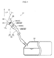
- a fuel tank filler structure (hereinafter simply called “the filler structure”) 20 of an embodiment of the present invention will be described below with reference to FIG. 1 to FIG. 5 .
- arrow UP appropriately shown in these drawings indicates a vehicle upward direction and that arrow X indicates an insertion direction of a later-described fuel nozzle 100 (hereinafter this direction will simply be called “the nozzle insertion direction”).
- the filler structure 20 of the present embodiment has a filler pipe 24 and an outside cover 28.
- the filler pipe 24 is equipped with a filler inlet 24A into which the fuel nozzle 100 is inserted. Furthermore, the filler pipe 24 is communicated with a fuel tank 22 and delivers to the fuel tank 22 fuel supplied from the fuel nozzle 100.
- the outside cover 28 is disposed in a flow path 26 in the filler pipe 24, closes off the filler inlet 24A, and, when it is pushed by the distal end portion of the fuel nozzle 100, opens the filler inlet 24A.
- the filler pipe 24 of the present embodiment is an example of a filler pipe of the present invention and that the outside cover 28 of the present embodiment is an example of an opening and closing valve of the present invention.
- the phrase “near side” when the phrase “near side” is simply used, this will be understood to mean the near side of the filler pipe 24, or in other words the filler inlet 24A side, and when the phrase “far side” is used, this will be understood to mean the far side of the filler pipe 24, or in other words the fuel tank 22 side.
- the phrase “radial direction” when the phrase “radial direction” is simply used, this will be understood to mean the radial direction of the filler pipe 24, and when the phrase “axial direction” is used, this will be understood to mean the axial direction of the filler pipe 24.
- the upper end portion of the filler pipe 24 is attached to the bottom portion of a recessed portion 32, which is formed in an outer panel configuring a vehicle body 30 and is recessed inward relative to the vehicle body 30. Furthermore, the lower end portion of the filler pipe 24 is connected to the upper portion of the fuel tank 22.
- the filler pipe 24 is equipped with a cylindrical filler inlet member 34 and a cylindrical pipe body 36.
- the filler inlet member 34 configures the filler inlet 24A and is attached to the bottom portion of the recessed portion 32.
- the pipe body 36 has the filler inlet member 34 attached to its upper end portion (the near-side end portion), and the lower end portion (the far-side end portion) of the pipe body 36 is connected to the fuel tank 22.
- the filler inlet member 34 is attached to the bottom portion of the recessed portion 32 in a state in which the filler inlet member 34 is inserted into an attachment hole 32A formed in the bottom portion of the recessed portion 32, and the near-side end portion (the upper end portion in FIG. 1 and FIG. 2 ) of the filler inlet member 34 is placed in the recessed portion 32. Furthermore, an annular jutting portion 38 that juts inward in the radial direction is formed on the near-side end portion of the filler inlet member 34. A circular opening formed inside the jutting portion 38 is the filler inlet 24A.
- a substantially cylindrical tube portion 40 having a shape whose inner diameter is gradually reduced heading from the near side toward the far side is formed in the axial direction intermediate portion (in the present embodiment, near the central portion) of the filler inlet member 34.
- An opening 42 formed in the far-side end portion of the tube portion 40 is slightly larger in diameter than the nozzle diameter of the fuel nozzle 100. Because of the tube portion 40, when the fuel nozzle 100 is inserted from the filler inlet 24A into the tube portion 40, the distal end portion of the fuel nozzle 100 comes into contact with an inner peripheral surface 40A of the tube portion 40 and is guided to the opening 42.
- annular rubber seal 44 is attached to the rim of the opening 42 in the tube portion 40 (in the present embodiment, the far-side end surface of the tube portion 40) along the rim.
- a first opening and closing portion 46 for opening and closing the opening 42 is disposed in the filler inlet member 34.
- the opening 42 is closed off by a flapper valve 48 configuring the first opening and closing portion 46.
- a second opening and closing portion 50 for opening and closing the filler inlet 24A is disposed in the filler inlet member 34 on the near side of the first opening and closing portion 46.
- the filler inlet 24A is closed off by the outside cover 28 configuring the second opening and closing portion 50.
- the flow path 26 in the filler pipe 24 is configured to include a first flow path 26A from the outside cover 28 to the flapper valve 48 and a second flow path 26B from the flapper valve 48 to the fuel tank 22.
- the first opening and closing portion 46 is equipped with the flapper valve 48, a spindle 52, and a biasing spring 54.
- the flapper valve 48 is substantially circular, formed in the shape of a flat plate, and is larger in diameter than the opening 42 in the tube portion 40. In a state in which the flapper valve 48 is closed (hereinafter appropriately called “the closed state"), the near-side surface of the flapper valve 48 is in contact with the rubber seal 44 so that the space between the tube portion 40 and the flapper valve 48 is sealed.
- a pair of bearing portions 48A are disposed on the end portion of the flapper valve 48.
- the spindle 52 which rotatably supports the flapper valve 48, is inserted through these bearing portions 48A.
- the spindle 52 is rotatably supported by a non-illustrated pair of bearing portions disposed in the filler inlet member 34. For this reason, the opening 42 is opened and closed when the flapper valve 48 is rotated about the spindle 52.
- the biasing spring 54 is wound around the spindle 52.
- the biasing spring 54 biases the flapper valve 48 in the closing direction.
- a torsion coil spring for example, is used.
- the flapper valve 48 is pushed by a force greater than the biasing force of the biasing spring 54, the flapper valve 48 rotates about the spindle 52 counter to the biasing force of the biasing spring 54 so that the opening 42 is opened.
- the second opening and closing portion 50 is equipped with the outside cover 28, a spindle 56, and a biasing spring 58.
- the outside cover 28 is substantially circular, formed in the shape of a flat plate, and is larger in diameter than the filler inlet 24A. Furthermore, the diameter of the outside cover 28 is formed larger than the diameter of the filler inlet 24A, so that in a state in which the outside cover 28 is closed as shown in FIG. 2 and FIG. 3 , the outer peripheral edge portion of the outside cover 28 and the rim of the filler inlet 24A are in contact with one another.
- a pair of bearing portions 28A are disposed on the end portion of the outside cover 28.
- the spindle 56 which rotatably supports the outside cover 28, is inserted through these bearing portions 28A.
- the spindle 56 is rotatably supported by a non-illustrated pair of bearing portions disposed in the filler inlet member 34. For this reason, the filler inlet 24A is opened and closed when the outside cover 28 is rotated about the spindle 56.
- the biasing spring 58 is wound around the spindle 56.
- the biasing spring 58 biases the outside cover 28 in the closing direction.
- a torsion coil spring for example, is used.
- the outside cover 28 when the outside cover 28 is pushed by a force greater than the biasing force of the biasing spring 58, the outside cover 28 rotates about the spindle 56 counter to the biasing force of the biasing spring 58 so that the filler inlet 24A is opened.
- a projecting portion 60 is disposed on the outside cover 28.
- the projecting portion 60 projects toward the opposite side of the nozzle insertion direction in the closed state of the outside cover 28, and part of the projecting portion 60 is exposed from the filler inlet 24A. In other words, the projecting portion 60 projects in the plate thickness direction of the outside cover 28.
- the projecting portion 60 has a cross-sectionally circular shape, and its outer diameter on its projecting distal end portion 60B side is smaller than its outer diameter on its base portion 60A side.
- a sloping surface 62 that extends from the projecting distal end portion 60B toward the base portion 60A is formed on the projecting portion 60.
- the sloping surface 62 slopes relative to the nozzle insertion direction.
- the entire surface on the projecting distal end portion 60B side of the projecting portion 60 is formed by the sloping surface 62.
- the projecting distal end portion 60B side of the projecting portion 60 has a substantially conical shape, and the conical surface on the projecting distal end portion 60B side having the substantially conical shape is the sloping surface 62.
- the sloping surface 62 of the projecting portion 60 is formed in the section of the projecting portion 60 exposed from the filler inlet 24A.
- the sloping surface 62 is formed in the section of the projecting portion 60 located more on the opposite side of the nozzle insertion direction than the filler inlet 24A. It should be noted that, in the present embodiment, the sloping surface 62 is formed more on the opposite side of the nozzle insertion direction than an edge portion 38A of the jutting portion 38.
- the projecting distal end portion 60B of the projecting portion 60 is disposed in the central portion of the projecting portion 60 and in the central portion of the filler inlet 24A, as seen from the nozzle insertion direction. Furthermore, in the closed state of the outside cover 28, an interstice between the peripheral wall of the projecting portion 60 and the inner wall of the filler inlet 24A is substantially constant.
- the projecting portion 60 exposed from the filler inlet 24A is disposed on the outside cover 28, and the sloping surface 62 that extends from the projecting distal end portion 60B toward the base portion 60A and slopes relative to the nozzle insertion direction is formed on the projecting portion 60.
- the sloping surface 62 that extends from the projecting distal end portion 60B toward the base portion 60A and slopes relative to the nozzle insertion direction is formed on the projecting portion 60.
- the component force F1 can be resolved into a component force F1a in the nozzle insertion direction (the direction in which the outside cover 28 opens) and a component force F1b in the direction of a right angle to the component force F1a (the direction of a right angle to the direction in which the outside cover 28 opens).
- the component force F1a is smaller than the pressure F that the outside cover 28 receives from the sprayed water W, so it is difficult for the outside cover 28 to be opened. That is, according to the filler structure 20, because the sloping surface 62 is formed on the projecting portion 60, it is difficult for the outside cover 28 to be opened even if the sprayed water W strikes it. Because of this, the sprayed water W can be kept from pushing open the outside cover 28 and entering the filler pipe 24.
- the spring load of the biasing spring 58 can be set low.
- the spring load of the biasing spring 58 is set low, the insertion force when inserting the fuel nozzle 100 can be reduced, so the work of inserting the fuel nozzle 100 into the filler inlet 24A during fueling becomes easy. That is, according to the filler structure 20, a balance can be achieved between the ease with which the fuel nozzle 100 is inserted and the difficulty with which the outside cover 28 is opened when the sprayed water W strikes it.
- the entire surface on the projecting distal end portion 60B side of the projecting portion 60 is formed by the sloping surface 62, so it is even more difficult for the outside cover 28 to be opened even if the sprayed water W strikes it.
- the sloping surface 62 of the projecting portion 60 is formed in the exposed section of the projecting portion 60, so the sprayed water W can be dispersed outside the filler inlet 24A. Because of this, water ingress from the filler inlet 24A into the filler pipe 24 can be effectively controlled.
- the projecting distal end portion 60B of the projecting portion 60 is disposed in the central portion of the projecting portion 60 and in the central portion of the filler inlet 24A, as seen from the nozzle insertion direction as shown in FIG. 3 , so the sprayed water W can be dispersed substantially evenly along the sloping surface 62 of the projecting portion 60 to the periphery of the filler inlet 24A. Because of this, water ingress from the filler inlet 24A into the filler pipe 24 can be controlled even more.
- the filler structure 20 has a configuration where the projecting distal end portion 60B of the projecting portion 60 is disposed in the central portion of the projecting portion 60 and in the central portion of the filler inlet 24A, as seen from the nozzle insertion direction, but the present invention is not limited to this configuration.
- the filler structure 20 may also have a configuration such as shown in FIG. 6 and FIG. 7 , in which a projecting portion 70 has a projecting distal end portion 70B that is disposed offset from the central portion of the projecting portion 70 and offset from the central portion of the filler inlet 24A, as seen from the nozzle insertion direction.
- the projecting portion 70 may also have a configuration where the projecting distal end portion 70B is disposed on the base portion 70A.
- the projecting portion 70 may have a configuration where the projecting distal end portion 70B is disposed on a straight line extending from the base portion 70A in the opposite direction of the nozzle insertion direction.
- the projecting distal end portion 60B side of the projecting portion 60 has a substantially conical shape, but the present invention is not limited to this configuration.
- the projecting distal end portion 60B side of the projecting portion 60 may also have a substantially pyramidal shape.
- the sloping surfaces 62 of the projecting portion 60 may be flat surfaces, sloping surfaces curving in a convex manner, or sloping surfaces curving in a concave manner. It should be noted that, from the standpoint of dispersing the nozzle insertion direction pressure of the sprayed water W, it is preferred that the sloping surfaces 62 be curved in a convex manner rather than being curved in a concave manner.
- the filler structure 20 has a configuration where the sloping surface 62 of the projecting portion 60 is placed more on the opposite side of the nozzle insertion direction than the filler inlet 24A, but the present invention is not limited to this configuration.
- a sloping surface 62 that extends from the projecting distal end portion 60B to the base portion 60A may also be formed on the projecting portion 60.
Landscapes
- Engineering & Computer Science (AREA)
- Life Sciences & Earth Sciences (AREA)
- Sustainable Development (AREA)
- Sustainable Energy (AREA)
- Chemical & Material Sciences (AREA)
- Combustion & Propulsion (AREA)
- Transportation (AREA)
- Mechanical Engineering (AREA)
- Cooling, Air Intake And Gas Exhaust, And Fuel Tank Arrangements In Propulsion Units (AREA)
Abstract
A fuel tank filler structure (20) has: a filler pipe (24) that is equipped with a filler inlet (24A) into which a fuel nozzle (100) is inserted, the filler pipe (24) being communicated with a fuel tank (22); an opening and closing valve (50) that is disposed in the filler pipe (24), closes off the filler inlet (24A), and, when pushed by the fuel nozzle (100), opens the filler inlet (24A); and a projecting portion (60, 70) that is disposed on the opening and closing valve (50), projects toward an opposite side from an insertion direction (X) of the fuel nozzle (100), is exposed from the filler inlet (24A), and is equipped with a sloping surface (62, 72) that extends from a projecting distal end portion (60B, 70B) toward a base portion (60A, 70A) and slopes relative to the insertion direction (X) of the fuel nozzle (100).
Description
- The present invention relates to a fuel tank filler structure.
- Japanese Patent Application Laid-open (JP-A) No.
2012-144152 - In the filler structure disclosed in
JP-A No. 2012-144152 - In view of this circumstance, it is an object of an aspect of the present invention to provide a fuel tank filler structure in which it is difficult for an opening and closing valve to be opened even if sprayed water strikes the opening and closing valve when washing the car.
- A fuel tank filler structure of a first aspect of the present has: a filler pipe that is equipped with a filler inlet into which a fuel nozzle is inserted, the filler pipe being communicated with a fuel tank; an opening and closing valve that is disposed in the filler pipe, closes off the filler inlet, and, when pushed by the fuel nozzle, opens the filler inlet; and a projecting portion that is disposed on the opening and closing valve, projects toward an opposite side from an insertion direction of the fuel nozzle, is exposed from the filler inlet, and is equipped with a sloping surface that extends from a projecting distal end portion toward a base portion and slopes relative to the insertion direction of the fuel nozzle.
- In the fuel tank filler structure of the first aspect, the projecting portion exposed from the filler inlet is disposed on the opening and closing valve, and the projecting portion is equipped with the sloping surface that extends from the projecting distal end portion toward the base portion and slopes relative to the insertion direction of the fuel nozzle. Here, if, when washing the car, sprayed water strikes the sloping surface of the projecting portion exposed from the filler inlet, the pressure of the water in the insertion direction of the fuel nozzle is dispersed in other directions by the sloping surface. Because of this, it is difficult for the opening and closing valve to be opened even if the sprayed water strikes it.
- A fuel tank filler structure of a second aspect of the present is the fuel tank filler structure of the first aspect, wherein an entire surface on the projecting distal end portion side of the projecting portion is formed by the sloping surface.
- In the fuel tank filler structure of the second aspect, the entire surface on the projecting distal end portion side of the projecting portion is formed by the sloping surface, so it is even more difficult for the opening and closing valve to be opened even if the sprayed water strikes it.
- A fuel tank filler structure of a third aspect of the present is the fuel tank filler structure of the second aspect, wherein the projecting distal end portion is disposed in a central portion of the projecting portion and in a central portion of the filler inlet, as seen from the insertion direction of the fuel nozzle.
- In the fuel tank filler structure of the third aspect, the projecting distal end portion of the projecting portion is disposed in the central portion of the projecting portion and in the central portion of the filler inlet, as seen from the insertion direction of the fuel nozzle. For this reason, the sprayed water can be dispersed substantially evenly along the sloping surface of the projecting portion to the periphery of the filler inlet.
- The fuel tank filler structure of the aspect of the present invention has the superior effect that it is difficult for the opening and closing valve to be opened even if sprayed water strikes the opening and closing valve when washing the car.
- Exemplary embodiments of the present invention will be described in detail based on the following figures, wherein:
-
FIG. 1 is a schematic configuration diagram of a fuel tank to which a fuel tank filler structure of an embodiment of the present invention has been applied; -
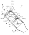
FIG. 2 is a cross-sectional view along an axial direction of a filler pipe used in the fuel tank filler structure of the embodiment of the present invention; -
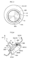
FIG. 3 is a front view of a filler inlet of the filler pipe ofFIG. 2 as seen from the insertion direction of a fuel nozzle; -
FIG. 4 is a cross-sectional view, corresponding to the section indicated by arrow 4 ofFIG. 2 , showing a state in which sprayed water is striking a projecting portion of an outside cover ofFIG. 2 ; -
FIG. 5 is an enlarged view in which part ofFIG. 4 is enlarged, and shows the directions of forces acting on the projecting portion in the state in which sprayed water is striking the projecting portion of the outside cover ofFIG. 4 ; -
FIG. 6 is a cross-sectional view corresponding toFIG. 4 showing a first example modification of the projecting portion of the embodiment of the present invention; and -
FIG. 7 is a front view corresponding toFIG. 3 showing the first example modification ofFIG. 6 . - A fuel tank filler structure (hereinafter simply called "the filler structure") 20 of an embodiment of the present invention will be described below with reference to
FIG. 1 to FIG. 5 . It should be noted that arrow UP appropriately shown in these drawings indicates a vehicle upward direction and that arrow X indicates an insertion direction of a later-described fuel nozzle 100 (hereinafter this direction will simply be called "the nozzle insertion direction"). - As shown in
FIG. 1 , thefiller structure 20 of the present embodiment has afiller pipe 24 and anoutside cover 28. Thefiller pipe 24 is equipped with afiller inlet 24A into which thefuel nozzle 100 is inserted. Furthermore, thefiller pipe 24 is communicated with afuel tank 22 and delivers to thefuel tank 22 fuel supplied from thefuel nozzle 100. Theoutside cover 28 is disposed in aflow path 26 in thefiller pipe 24, closes off thefiller inlet 24A, and, when it is pushed by the distal end portion of thefuel nozzle 100, opens thefiller inlet 24A. It should be noted that thefiller pipe 24 of the present embodiment is an example of a filler pipe of the present invention and that theoutside cover 28 of the present embodiment is an example of an opening and closing valve of the present invention. - Furthermore, in the present embodiment, when the phrase "near side" is simply used, this will be understood to mean the near side of the
filler pipe 24, or in other words the filler inlet 24A side, and when the phrase "far side" is used, this will be understood to mean the far side of thefiller pipe 24, or in other words thefuel tank 22 side. Furthermore, when the phrase "radial direction" is simply used, this will be understood to mean the radial direction of thefiller pipe 24, and when the phrase "axial direction" is used, this will be understood to mean the axial direction of thefiller pipe 24. - The upper end portion of the
filler pipe 24 is attached to the bottom portion of arecessed portion 32, which is formed in an outer panel configuring avehicle body 30 and is recessed inward relative to thevehicle body 30. Furthermore, the lower end portion of thefiller pipe 24 is connected to the upper portion of thefuel tank 22. - As shown in
FIG. 2 , thefiller pipe 24 is equipped with a cylindricalfiller inlet member 34 and acylindrical pipe body 36. Thefiller inlet member 34 configures thefiller inlet 24A and is attached to the bottom portion of therecessed portion 32. Thepipe body 36 has thefiller inlet member 34 attached to its upper end portion (the near-side end portion), and the lower end portion (the far-side end portion) of thepipe body 36 is connected to thefuel tank 22. - The
filler inlet member 34 is attached to the bottom portion of therecessed portion 32 in a state in which thefiller inlet member 34 is inserted into anattachment hole 32A formed in the bottom portion of therecessed portion 32, and the near-side end portion (the upper end portion inFIG. 1 andFIG. 2 ) of thefiller inlet member 34 is placed in therecessed portion 32. Furthermore, anannular jutting portion 38 that juts inward in the radial direction is formed on the near-side end portion of thefiller inlet member 34. A circular opening formed inside the juttingportion 38 is thefiller inlet 24A. - A substantially
cylindrical tube portion 40 having a shape whose inner diameter is gradually reduced heading from the near side toward the far side is formed in the axial direction intermediate portion (in the present embodiment, near the central portion) of thefiller inlet member 34. Anopening 42 formed in the far-side end portion of thetube portion 40 is slightly larger in diameter than the nozzle diameter of thefuel nozzle 100. Because of thetube portion 40, when thefuel nozzle 100 is inserted from thefiller inlet 24A into thetube portion 40, the distal end portion of thefuel nozzle 100 comes into contact with an innerperipheral surface 40A of thetube portion 40 and is guided to theopening 42. - Furthermore, an
annular rubber seal 44 is attached to the rim of theopening 42 in the tube portion 40 (in the present embodiment, the far-side end surface of the tube portion 40) along the rim. - A first opening and
closing portion 46 for opening and closing theopening 42 is disposed in thefiller inlet member 34. The opening 42 is closed off by aflapper valve 48 configuring the first opening andclosing portion 46. - Furthermore, a second opening and closing
portion 50 for opening and closing thefiller inlet 24A is disposed in thefiller inlet member 34 on the near side of the first opening andclosing portion 46. Thefiller inlet 24A is closed off by theoutside cover 28 configuring the second opening andclosing portion 50. - For this reason, the
flow path 26 in thefiller pipe 24 is configured to include afirst flow path 26A from theoutside cover 28 to theflapper valve 48 and asecond flow path 26B from theflapper valve 48 to thefuel tank 22. - As shown in
FIG. 2 the first opening andclosing portion 46 is equipped with theflapper valve 48, aspindle 52, and a biasingspring 54. Theflapper valve 48 is substantially circular, formed in the shape of a flat plate, and is larger in diameter than theopening 42 in thetube portion 40. In a state in which theflapper valve 48 is closed (hereinafter appropriately called "the closed state"), the near-side surface of theflapper valve 48 is in contact with therubber seal 44 so that the space between thetube portion 40 and theflapper valve 48 is sealed. - A pair of bearing
portions 48A are disposed on the end portion of theflapper valve 48. - The
spindle 52, which rotatably supports theflapper valve 48, is inserted through these bearingportions 48A. Thespindle 52 is rotatably supported by a non-illustrated pair of bearing portions disposed in thefiller inlet member 34. For this reason, theopening 42 is opened and closed when theflapper valve 48 is rotated about thespindle 52. Furthermore, the biasingspring 54 is wound around thespindle 52. Thebiasing spring 54 biases theflapper valve 48 in the closing direction. For the biasingspring 54 of the present embodiment, a torsion coil spring, for example, is used. Here, when theflapper valve 48 is pushed by a force greater than the biasing force of the biasingspring 54, theflapper valve 48 rotates about thespindle 52 counter to the biasing force of the biasingspring 54 so that theopening 42 is opened. - The second opening and closing
portion 50 is equipped with theoutside cover 28, aspindle 56, and a biasingspring 58. Theoutside cover 28 is substantially circular, formed in the shape of a flat plate, and is larger in diameter than thefiller inlet 24A. Furthermore, the diameter of theoutside cover 28 is formed larger than the diameter of thefiller inlet 24A, so that in a state in which theoutside cover 28 is closed as shown inFIG. 2 andFIG. 3 , the outer peripheral edge portion of theoutside cover 28 and the rim of thefiller inlet 24A are in contact with one another. - A pair of bearing
portions 28A are disposed on the end portion of theoutside cover 28. Thespindle 56, which rotatably supports theoutside cover 28, is inserted through these bearingportions 28A. Thespindle 56 is rotatably supported by a non-illustrated pair of bearing portions disposed in thefiller inlet member 34. For this reason, thefiller inlet 24A is opened and closed when theoutside cover 28 is rotated about thespindle 56. Furthermore, the biasingspring 58 is wound around thespindle 56. The biasingspring 58 biases theoutside cover 28 in the closing direction. For the biasingspring 58 of the present embodiment, a torsion coil spring, for example, is used. Here, when theoutside cover 28 is pushed by a force greater than the biasing force of the biasingspring 58, theoutside cover 28 rotates about thespindle 56 counter to the biasing force of the biasingspring 58 so that thefiller inlet 24A is opened. - Furthermore, as shown in
FIG. 2 to FIG. 4 , a projectingportion 60 is disposed on theoutside cover 28. The projectingportion 60 projects toward the opposite side of the nozzle insertion direction in the closed state of theoutside cover 28, and part of the projectingportion 60 is exposed from thefiller inlet 24A. In other words, the projectingportion 60 projects in the plate thickness direction of theoutside cover 28. - The projecting
portion 60 has a cross-sectionally circular shape, and its outer diameter on its projectingdistal end portion 60B side is smaller than its outer diameter on itsbase portion 60A side. A slopingsurface 62 that extends from the projectingdistal end portion 60B toward thebase portion 60A is formed on the projectingportion 60. The slopingsurface 62 slopes relative to the nozzle insertion direction. Furthermore, in the present embodiment, the entire surface on the projectingdistal end portion 60B side of the projectingportion 60 is formed by the slopingsurface 62. Specifically, the projectingdistal end portion 60B side of the projectingportion 60 has a substantially conical shape, and the conical surface on the projectingdistal end portion 60B side having the substantially conical shape is the slopingsurface 62. - Furthermore, the sloping
surface 62 of the projectingportion 60 is formed in the section of the projectingportion 60 exposed from thefiller inlet 24A. In other words, the slopingsurface 62 is formed in the section of the projectingportion 60 located more on the opposite side of the nozzle insertion direction than thefiller inlet 24A. It should be noted that, in the present embodiment, the slopingsurface 62 is formed more on the opposite side of the nozzle insertion direction than anedge portion 38A of the juttingportion 38. - The projecting
distal end portion 60B of the projectingportion 60 is disposed in the central portion of the projectingportion 60 and in the central portion of thefiller inlet 24A, as seen from the nozzle insertion direction. Furthermore, in the closed state of theoutside cover 28, an interstice between the peripheral wall of the projectingportion 60 and the inner wall of thefiller inlet 24A is substantially constant. - Next, the action and effects of the
filler structure 20 of the present embodiment will be described. - In the
filler structure 20, the projectingportion 60 exposed from thefiller inlet 24A is disposed on theoutside cover 28, and the slopingsurface 62 that extends from the projectingdistal end portion 60B toward thebase portion 60A and slopes relative to the nozzle insertion direction is formed on the projectingportion 60. Here, if, after fueling, one forgets to close afuel lid 68 covering thefiller inlet 24A, washes the car, and sprayed water W strikes the slopingsurface 62 of the projectingportion 60 exposed from thefiller inlet 24A, the pressure of the water W in the nozzle insertion direction is dispersed in other directions by the slopingsurface 62. - Specifically, as shown in
FIG. 5 , when the sprayed water W strikes the slopingsurface 62 of the projectingportion 60 of theoutside cover 28 and theoutside cover 28 receives pressure F in the nozzle insertion direction from the water W, the pressure F is dispersed by the slopingsurface 62 into a component force F1 in the direction of a right angle to the slopingsurface 62 and a component force F2 parallel to the slopingsurface 62. The component force F1 can be resolved into a component force F1a in the nozzle insertion direction (the direction in which theoutside cover 28 opens) and a component force F1b in the direction of a right angle to the component force F1a (the direction of a right angle to the direction in which theoutside cover 28 opens). Here, the component force F1a is smaller than the pressure F that theoutside cover 28 receives from the sprayed water W, so it is difficult for theoutside cover 28 to be opened. That is, according to thefiller structure 20, because the slopingsurface 62 is formed on the projectingportion 60, it is difficult for theoutside cover 28 to be opened even if the sprayed water W strikes it. Because of this, the sprayed water W can be kept from pushing open theoutside cover 28 and entering thefiller pipe 24. - Furthermore, in the
filler structure 20, because the pressure F that theoutside cover 28 receives from the sprayed water W is dispersed by the slopingsurface 62, it can be made difficult for theoutside cover 28 to be opened, so the spring load of the biasingspring 58 can be set low. Here, for example, if the spring load of the biasingspring 58 is set low, the insertion force when inserting thefuel nozzle 100 can be reduced, so the work of inserting thefuel nozzle 100 into thefiller inlet 24A during fueling becomes easy. That is, according to thefiller structure 20, a balance can be achieved between the ease with which thefuel nozzle 100 is inserted and the difficulty with which theoutside cover 28 is opened when the sprayed water W strikes it. - In the
filler structure 20, the entire surface on the projectingdistal end portion 60B side of the projectingportion 60 is formed by the slopingsurface 62, so it is even more difficult for theoutside cover 28 to be opened even if the sprayed water W strikes it. - Furthermore, in the
filler structure 20, the slopingsurface 62 of the projectingportion 60 is formed in the exposed section of the projectingportion 60, so the sprayed water W can be dispersed outside thefiller inlet 24A. Because of this, water ingress from thefiller inlet 24A into thefiller pipe 24 can be effectively controlled. - Moreover, in the
filler structure 20, the projectingdistal end portion 60B of the projectingportion 60 is disposed in the central portion of the projectingportion 60 and in the central portion of thefiller inlet 24A, as seen from the nozzle insertion direction as shown inFIG. 3 , so the sprayed water W can be dispersed substantially evenly along the slopingsurface 62 of the projectingportion 60 to the periphery of thefiller inlet 24A. Because of this, water ingress from thefiller inlet 24A into thefiller pipe 24 can be controlled even more. - In the preceding embodiment, the
filler structure 20 has a configuration where the projectingdistal end portion 60B of the projectingportion 60 is disposed in the central portion of the projectingportion 60 and in the central portion of thefiller inlet 24A, as seen from the nozzle insertion direction, but the present invention is not limited to this configuration. For example, thefiller structure 20 may also have a configuration such as shown inFIG. 6 and FIG. 7 , in which a projectingportion 70 has a projectingdistal end portion 70B that is disposed offset from the central portion of the projectingportion 70 and offset from the central portion of thefiller inlet 24A, as seen from the nozzle insertion direction. It should be noted thatreference sign 70A inFIG. 6 and FIG. 7 denotes an example of the base portion of the projectingportion 70 of the present invention, thatreference sign 70B denotes an example of the projecting distal end portion of the projectingportion 70 of the present invention, and thatreference sign 72 denotes an example of the sloping surface of the present invention. Furthermore, for example, the projectingportion 70 may also have a configuration where the projectingdistal end portion 70B is disposed on thebase portion 70A. Specifically, the projectingportion 70 may have a configuration where the projectingdistal end portion 70B is disposed on a straight line extending from thebase portion 70A in the opposite direction of the nozzle insertion direction. - Furthermore, in the preceding embodiment, the projecting
distal end portion 60B side of the projectingportion 60 has a substantially conical shape, but the present invention is not limited to this configuration. For example, the projectingdistal end portion 60B side of the projectingportion 60 may also have a substantially pyramidal shape. In this case, the slopingsurfaces 62 of the projectingportion 60 may be flat surfaces, sloping surfaces curving in a convex manner, or sloping surfaces curving in a concave manner. It should be noted that, from the standpoint of dispersing the nozzle insertion direction pressure of the sprayed water W, it is preferred that the slopingsurfaces 62 be curved in a convex manner rather than being curved in a concave manner. - Moreover, in the preceding embodiment, the
filler structure 20 has a configuration where the slopingsurface 62 of the projectingportion 60 is placed more on the opposite side of the nozzle insertion direction than thefiller inlet 24A, but the present invention is not limited to this configuration. For example, a slopingsurface 62 that extends from the projectingdistal end portion 60B to thebase portion 60A may also be formed on the projectingportion 60. - An embodiment of the present invention has been described above, but the present invention is not limited to what has been described above and can of course be modified and implemented in a variety of ways other than those described above without departing from the spirit thereof.
- All documents, patent applications, and technical standards mentioned in this specification are incorporated by reference herein to the same extent as if each individual document, patent application, and technical standard were specifically and individually indicated to be incorporated by reference.
Claims (3)
- A fuel tank filler structure (20) comprising:a filler pipe (24) that is equipped with a filler (24A) for receiving which a fuel nozzle (100), the filler pipe being configured to communicate with a fuel tank (22);an opening and closing valve (50) that is disposed in the filler pipe (24), closes off the filler inlet (24A), and, when pushed by the fuel nozzle (100), opens the filler inlet (24A); anda projecting portion (60, 70) that is disposed on the opening and closing valve (50), projects toward an opposite side from an insertion direction (X) of the fuel nozzle (100), is exposed from the filler inlet (24A), and is equipped with a sloping surface (62, 72) that extends from a projecting distal end portion (60B, 70B) toward a base portion (60A, 70A) and slopes relative to the insertion direction (X) of the fuel nozzle (100).
- The fuel tank filler structure (20) according to claim 1, wherein an entire surface on the projecting distal end portion side of the projecting portion (60, 70) is formed by the sloping surface (62, 72).
- The fuel tank filler structure (20) according to claim 2, wherein the projecting distal end portion (60B) is disposed in a central portion of the projecting portion (60) and in a central portion of the filler inlet (24A), as seen from the insertion direction of the fuel nozzle (100).
Applications Claiming Priority (1)
| Application Number | Priority Date | Filing Date | Title |
|---|---|---|---|
| JP2014223335A JP2016088218A (en) | 2014-10-31 | 2014-10-31 | Fuel tank fueling part structure |
Publications (1)
| Publication Number | Publication Date |
|---|---|
| EP3015304A1 true EP3015304A1 (en) | 2016-05-04 |
Family
ID=54427566
Family Applications (1)
| Application Number | Title | Priority Date | Filing Date |
|---|---|---|---|
| EP15191995.8A Withdrawn EP3015304A1 (en) | 2014-10-31 | 2015-10-29 | Fuel tank filler structure |
Country Status (3)
| Country | Link |
|---|---|
| US (1) | US20160121716A1 (en) |
| EP (1) | EP3015304A1 (en) |
| JP (1) | JP2016088218A (en) |
Families Citing this family (3)
| Publication number | Priority date | Publication date | Assignee | Title |
|---|---|---|---|---|
| DE112013001045T5 (en) * | 2012-02-20 | 2014-12-04 | Honda Motor Co., Ltd. | Structure for a filling section of a fuel filler pipe |
| DE102014111834A1 (en) * | 2014-08-19 | 2016-02-25 | Illinois Tool Works Inc. | Filling device for a fuel tank |
| JP2018069856A (en) * | 2016-10-26 | 2018-05-10 | 住友理工株式会社 | Lubrication device |
Citations (5)
| Publication number | Priority date | Publication date | Assignee | Title |
|---|---|---|---|---|
| US4091959A (en) * | 1977-02-03 | 1978-05-30 | Banion John D O | Gas cap |
| EP1415844A2 (en) * | 2002-11-04 | 2004-05-06 | Stant Manufacturing Inc. | Dust cover lock system for vehicle filler neck |
| EP1637382A1 (en) * | 2004-09-17 | 2006-03-22 | Stant Manufacturing Inc. | Breakaway closure for capless tank filler neck |
| US20110079322A1 (en) * | 2009-10-07 | 2011-04-07 | Ford Global Technologies, Llc | Fuel filler system |
| JP2012144152A (en) | 2011-01-12 | 2012-08-02 | Toyota Motor Corp | Oil feeding part structure of fuel tank |
-
2014
- 2014-10-31 JP JP2014223335A patent/JP2016088218A/en not_active Withdrawn
-
2015
- 2015-10-22 US US14/920,139 patent/US20160121716A1/en not_active Abandoned
- 2015-10-29 EP EP15191995.8A patent/EP3015304A1/en not_active Withdrawn
Patent Citations (5)
| Publication number | Priority date | Publication date | Assignee | Title |
|---|---|---|---|---|
| US4091959A (en) * | 1977-02-03 | 1978-05-30 | Banion John D O | Gas cap |
| EP1415844A2 (en) * | 2002-11-04 | 2004-05-06 | Stant Manufacturing Inc. | Dust cover lock system for vehicle filler neck |
| EP1637382A1 (en) * | 2004-09-17 | 2006-03-22 | Stant Manufacturing Inc. | Breakaway closure for capless tank filler neck |
| US20110079322A1 (en) * | 2009-10-07 | 2011-04-07 | Ford Global Technologies, Llc | Fuel filler system |
| JP2012144152A (en) | 2011-01-12 | 2012-08-02 | Toyota Motor Corp | Oil feeding part structure of fuel tank |
Also Published As
| Publication number | Publication date |
|---|---|
| US20160121716A1 (en) | 2016-05-05 |
| JP2016088218A (en) | 2016-05-23 |
Similar Documents
| Publication | Publication Date | Title |
|---|---|---|
| JP6200097B2 (en) | Valve case mounting structure | |
| US9102230B2 (en) | Fuel tank opening and closing device | |
| EP3015304A1 (en) | Fuel tank filler structure | |
| US9725291B2 (en) | Refueling auxiliary device | |
| EP1574155A3 (en) | Closure assembly for drinking vessel | |
| CN101171167A (en) | Valves for car bodies | |
| CN103459184A (en) | Fuel-filler aperture opening/closing device | |
| JP5926051B2 (en) | Refueling port | |
| WO2009002771A3 (en) | Slit valve door | |
| EP3187356B1 (en) | Fuel tank check valve | |
| US11009147B2 (en) | Valve device for fuel tank | |
| US8087434B2 (en) | Filler neck for the fuel tank of a vehicle | |
| CN106715177B (en) | Weighted Baffles and Splined Orifice Plates for Exhaust Valves | |
| JP4504772B2 (en) | Fuel tank refueling pipe | |
| EP3130499B1 (en) | Oil filler port opening and closing device | |
| JP2013136263A5 (en) | ||
| US8490642B2 (en) | Fuel-outflow check valve | |
| US20150034180A1 (en) | Tank pressure control solenoid with passive tank vacuum relief | |
| KR20190056022A (en) | Over slam bumper | |
| JP2016113101A (en) | Fuel supply part structure of fuel tank | |
| US20160123486A1 (en) | Relief valve | |
| US12090837B2 (en) | Over-fueling prevention valve | |
| US8746479B2 (en) | Method of closing a fuel tank with a pivotal door and seal | |
| US9919596B2 (en) | Open-close device for fuel tank | |
| JP2012007640A (en) | Relief valve |
Legal Events
| Date | Code | Title | Description |
|---|---|---|---|
| PUAI | Public reference made under article 153(3) epc to a published international application that has entered the european phase |
Free format text: ORIGINAL CODE: 0009012 |
|
| 17P | Request for examination filed |
Effective date: 20151029 |
|
| AK | Designated contracting states |
Kind code of ref document: A1 Designated state(s): AL AT BE BG CH CY CZ DE DK EE ES FI FR GB GR HR HU IE IS IT LI LT LU LV MC MK MT NL NO PL PT RO RS SE SI SK SM TR |
|
| AX | Request for extension of the european patent |
Extension state: BA ME |
|
| STAA | Information on the status of an ep patent application or granted ep patent |
Free format text: STATUS: REQUEST FOR EXAMINATION WAS MADE |
|
| STAA | Information on the status of an ep patent application or granted ep patent |
Free format text: STATUS: THE APPLICATION IS DEEMED TO BE WITHDRAWN |
|
| 18D | Application deemed to be withdrawn |
Effective date: 20161105 |