EP3015297A1 - Anordnung mit einem Filterelement - Google Patents
Anordnung mit einem Filterelement Download PDFInfo
- Publication number
- EP3015297A1 EP3015297A1 EP14190869.9A EP14190869A EP3015297A1 EP 3015297 A1 EP3015297 A1 EP 3015297A1 EP 14190869 A EP14190869 A EP 14190869A EP 3015297 A1 EP3015297 A1 EP 3015297A1
- Authority
- EP
- European Patent Office
- Prior art keywords
- filter element
- water
- bellows
- edge strip
- arrangement according
- Prior art date
- Legal status (The legal status is an assumption and is not a legal conclusion. Google has not performed a legal analysis and makes no representation as to the accuracy of the status listed.)
- Granted
Links
- XLYOFNOQVPJJNP-UHFFFAOYSA-N water Substances O XLYOFNOQVPJJNP-UHFFFAOYSA-N 0.000 claims abstract description 38
- 239000005871 repellent Substances 0.000 claims abstract description 9
- -1 polypropylene Polymers 0.000 claims description 10
- 239000000835 fiber Substances 0.000 claims description 6
- 239000004745 nonwoven fabric Substances 0.000 claims description 6
- 239000004743 Polypropylene Substances 0.000 claims description 4
- 229920001155 polypropylene Polymers 0.000 claims description 4
- 239000004952 Polyamide Substances 0.000 claims description 3
- 239000004698 Polyethylene Substances 0.000 claims description 3
- 239000000203 mixture Substances 0.000 claims description 3
- 229920002647 polyamide Polymers 0.000 claims description 3
- 229920000573 polyethylene Polymers 0.000 claims description 3
- 239000011248 coating agent Substances 0.000 claims description 2
- 238000000576 coating method Methods 0.000 claims description 2
- 238000001914 filtration Methods 0.000 claims description 2
- 239000002121 nanofiber Substances 0.000 claims description 2
- 238000004378 air conditioning Methods 0.000 abstract description 4
- 230000002940 repellent Effects 0.000 abstract description 2
- 230000000694 effects Effects 0.000 description 5
- OKTJSMMVPCPJKN-UHFFFAOYSA-N Carbon Chemical compound [C] OKTJSMMVPCPJKN-UHFFFAOYSA-N 0.000 description 4
- 229920000139 polyethylene terephthalate Polymers 0.000 description 3
- 239000005020 polyethylene terephthalate Substances 0.000 description 3
- 239000000428 dust Substances 0.000 description 2
- 239000000463 material Substances 0.000 description 2
- 241000533950 Leucojum Species 0.000 description 1
- 238000007664 blowing Methods 0.000 description 1
- 238000004140 cleaning Methods 0.000 description 1
- 238000011109 contamination Methods 0.000 description 1
- 230000008021 deposition Effects 0.000 description 1
- 239000010419 fine particle Substances 0.000 description 1
- 238000011044 inertial separation Methods 0.000 description 1
- 238000001746 injection moulding Methods 0.000 description 1
- 239000007788 liquid Substances 0.000 description 1
- 230000004048 modification Effects 0.000 description 1
- 238000012986 modification Methods 0.000 description 1
- 239000002245 particle Substances 0.000 description 1
- 238000011045 prefiltration Methods 0.000 description 1
- 238000005406 washing Methods 0.000 description 1
Images


Classifications
-
- B—PERFORMING OPERATIONS; TRANSPORTING
- B01—PHYSICAL OR CHEMICAL PROCESSES OR APPARATUS IN GENERAL
- B01D—SEPARATION
- B01D46/00—Filters or filtering processes specially modified for separating dispersed particles from gases or vapours
- B01D46/30—Particle separators, e.g. dust precipitators, using loose filtering material
-
- B—PERFORMING OPERATIONS; TRANSPORTING
- B60—VEHICLES IN GENERAL
- B60H—ARRANGEMENTS OF HEATING, COOLING, VENTILATING OR OTHER AIR-TREATING DEVICES SPECIALLY ADAPTED FOR PASSENGER OR GOODS SPACES OF VEHICLES
- B60H3/00—Other air-treating devices
- B60H3/06—Filtering
- B60H3/0658—Filter elements specially adapted for their arrangement in vehicles
-
- B—PERFORMING OPERATIONS; TRANSPORTING
- B01—PHYSICAL OR CHEMICAL PROCESSES OR APPARATUS IN GENERAL
- B01D—SEPARATION
- B01D46/00—Filters or filtering processes specially modified for separating dispersed particles from gases or vapours
- B01D46/0027—Filters or filtering processes specially modified for separating dispersed particles from gases or vapours with additional separating or treating functions
- B01D46/003—Filters or filtering processes specially modified for separating dispersed particles from gases or vapours with additional separating or treating functions including coalescing means for the separation of liquid
- B01D46/0031—Filters or filtering processes specially modified for separating dispersed particles from gases or vapours with additional separating or treating functions including coalescing means for the separation of liquid with collecting, draining means
-
- B—PERFORMING OPERATIONS; TRANSPORTING
- B01—PHYSICAL OR CHEMICAL PROCESSES OR APPARATUS IN GENERAL
- B01D—SEPARATION
- B01D46/00—Filters or filtering processes specially modified for separating dispersed particles from gases or vapours
- B01D46/0039—Filters or filtering processes specially modified for separating dispersed particles from gases or vapours with flow guiding by feed or discharge devices
-
- B—PERFORMING OPERATIONS; TRANSPORTING
- B01—PHYSICAL OR CHEMICAL PROCESSES OR APPARATUS IN GENERAL
- B01D—SEPARATION
- B01D46/00—Filters or filtering processes specially modified for separating dispersed particles from gases or vapours
- B01D46/10—Particle separators, e.g. dust precipitators, using filter plates, sheets or pads having plane surfaces
-
- B—PERFORMING OPERATIONS; TRANSPORTING
- B01—PHYSICAL OR CHEMICAL PROCESSES OR APPARATUS IN GENERAL
- B01D—SEPARATION
- B01D46/00—Filters or filtering processes specially modified for separating dispersed particles from gases or vapours
- B01D46/52—Particle separators, e.g. dust precipitators, using filters embodying folded corrugated or wound sheet material
- B01D46/521—Particle separators, e.g. dust precipitators, using filters embodying folded corrugated or wound sheet material using folded, pleated material
- B01D46/523—Particle separators, e.g. dust precipitators, using filters embodying folded corrugated or wound sheet material using folded, pleated material with means for maintaining spacing between the pleats or folds
-
- B—PERFORMING OPERATIONS; TRANSPORTING
- B01—PHYSICAL OR CHEMICAL PROCESSES OR APPARATUS IN GENERAL
- B01D—SEPARATION
- B01D46/00—Filters or filtering processes specially modified for separating dispersed particles from gases or vapours
- B01D46/56—Filters or filtering processes specially modified for separating dispersed particles from gases or vapours with multiple filtering elements, characterised by their mutual disposition
- B01D46/62—Filters or filtering processes specially modified for separating dispersed particles from gases or vapours with multiple filtering elements, characterised by their mutual disposition connected in series
-
- B—PERFORMING OPERATIONS; TRANSPORTING
- B60—VEHICLES IN GENERAL
- B60H—ARRANGEMENTS OF HEATING, COOLING, VENTILATING OR OTHER AIR-TREATING DEVICES SPECIALLY ADAPTED FOR PASSENGER OR GOODS SPACES OF VEHICLES
- B60H3/00—Other air-treating devices
- B60H3/06—Filtering
- B60H3/0608—Filter arrangements in the air stream
- B60H3/0625—Filter arrangements in the air stream with provisions for by-passing the filter element
-
- B—PERFORMING OPERATIONS; TRANSPORTING
- B60—VEHICLES IN GENERAL
- B60H—ARRANGEMENTS OF HEATING, COOLING, VENTILATING OR OTHER AIR-TREATING DEVICES SPECIALLY ADAPTED FOR PASSENGER OR GOODS SPACES OF VEHICLES
- B60H3/00—Other air-treating devices
- B60H3/06—Filtering
- B60H3/0608—Filter arrangements in the air stream
- B60H3/0641—Filter arrangements in the air stream near ventilating openings in the vehicle exterior
-
- B—PERFORMING OPERATIONS; TRANSPORTING
- B01—PHYSICAL OR CHEMICAL PROCESSES OR APPARATUS IN GENERAL
- B01D—SEPARATION
- B01D2275/00—Filter media structures for filters specially adapted for separating dispersed particles from gases or vapours
- B01D2275/10—Multiple layers
-
- B—PERFORMING OPERATIONS; TRANSPORTING
- B01—PHYSICAL OR CHEMICAL PROCESSES OR APPARATUS IN GENERAL
- B01D—SEPARATION
- B01D2279/00—Filters adapted for separating dispersed particles from gases or vapours specially modified for specific uses
- B01D2279/50—Filters adapted for separating dispersed particles from gases or vapours specially modified for specific uses for air conditioning
Definitions
- the invention relates to an arrangement according to the preamble of patent claim 1.
- the cabin interior air is sucked under the windshield, namely in the water tank.
- this area of a motor vehicle intended for suction can be added, in particular snow-covered.
- Snow or melt water can then be sucked into the air conditioning system, in particular in the direction of a filter element.
- the air conditioner can be damaged by water ingress.
- a fleece which is installed in an interior, can contain activated carbon and is arranged behind components to be protected.
- a wet filter element moistens additional fresh air and activated carbon is ineffective by moisture.
- the invention is therefore based on the object, snow and water, especially melt water, so dissipate that they do not flow as possible in the air conditioning of a motor vehicle and damage a filter element as little as possible.
- an already known filter element can be used by a suitable modification to protect an intake manifold.
- the filter element protects the intake manifold against snow and water and specifically prevents the intake manifold from becoming snowed.
- the modified filter element effects a guided discharge of melt water.
- the filter element is cleaned by the outflowing melt water.
- the cross-flow effect very long service life of the filter element can be achieved. Since the filter element is installed with a slight inclination, the "cross-flow” effect that cleans the filter medium is always created by the water flowing out. This happens, for example, even in the rain or in a car wash. In that regard, snow and water, especially melt water, so dissipated that they are not possible in the Air conditioning of a motor vehicle flow and damage a filter element as little as possible.
- each on one side of the bellows fold edges could follow a zig-zag line or wavy line, wherein the fold edges are lined on at least one side of the bellows by an edge strip and wherein the edge strip is arranged or formed at the fold edges such that at least one Faltental water can drain off.
- the means for the drainage comprise an edge strip, which is suitably arranged. The edge strip stabilizes the pleat gap, seals and still gives an opening for the water drain.
- the means for water drainage are designed as V-shaped openings.
- the height of these openings is easily adjustable over the width of the edge strip.
- the edge strip could be designed as an injection-molded component.
- drain holes for melt water can be introduced specifically.
- an injection-molded component with an intake manifold can be locked well.
- Locking means may be formed, which is positively or non-positively connected to a counterpart on the intake manifold.
- the filter medium could comprise a water-repellent nonwoven fabric, wherein the filter medium comprises one to three layers, wherein the filter medium and / or at least one layer comprises fibers of polyethylene terephthalate, polypropylene, polyamide or polyethylene or wherein the filter medium and / or at least one layer comprises mixtures of the above comprising said fibers.
- the filter medium can be made suitable water repellent.
- the filter medium could preferably consist of water-repellent nonwoven fabric.
- the layer or layers are preferably formed as one-component or in each case of the same material.
- the nonwoven fabric could have a coating of nanofibers. As a result, very fine particles can be deposited.
- the intake manifold could be arranged in a water tank of a motor vehicle.
- the pleated, namely folded, filter element could be dimensioned such that it fits on the intake manifold for the réelleraumzuluft, which is arranged in the water tank of the motor vehicle.
- the filter medium could preferably be electrostatically uncharged.
- the filter element described here can simultaneously serve as a prefilter for separating coarse dust.
- the filter element described here can be designed as a "lifetime" component or be cleanable.
- the cleaning can be done by blowing or active washing.
- the filter element described herein may be used as or in combination with an inertial separator.
- an inertial separation is combined with the above-mentioned "cross-flow" effect.
- the filter element described here can be used in all motor vehicles, in which fresh air is sucked through the water tank.
- the filter element can be used in particular for filtering the supply air of an air conditioner.
- Fig. 1 shows an assembly comprising an intake manifold 1 with an air inlet, not shown, for an air conditioner and a filter element 2 with a bellows 3, the folding valleys 4 and 5 folded mountains, wherein the filter element 2 comprises a water-repellent filter medium and wherein the Filter element 2 covers the air inlet at least partially. Specifically, it is shown that the filter element 2 completely covers the air inlet.
- the filter element 2 reduces the amount of air by about 5 - 30% and allows a deposition of snowflakes in the size range of 10 .mu.m - 200 .mu.m.
- This arrangement is installed in a motor vehicle, not shown.
- the bellows 3 is in the installed state, namely when the motor vehicle is on a non-inclined plane, arranged inclined to the horizontal at an angle of 5 - 90 °, wherein the filter element 2 has means 6 for a water outlet from the Faltentälern 4.
- fold edges 7 follow a zig-zag line or wavy line, wherein the fold edges 7 are lined on at least one side of the bellows 3 by an edge strip 8 and wherein the edge strip 8 so arranged or formed at the fold edges 7 is that at least one Faltental 4 water can drain.
- a groove 9 is formed, which is not closed by the edge strip 7.
- the means 6 are designed for a water drain as a cross-sectionally V-shaped, not sealed by the edge strip 8 openings.
- the filter medium comprises a water-repellent nonwoven fabric, wherein the filter medium comprises one to three layers, wherein the filter medium and / or at least one layer comprises fibers of polyethylene terephthalate, polypropylene, polyamide or polyethylene or wherein the filter medium and / or at least one layer mixtures of the above comprising said fibers.
- the filter medium is made of polypropylene and has a basis weight of 105 g / m 2 .
- the filter element 2 is 195 mm long and 110 mm wide.
- the pleat distance is 10 mm.
- a pleat spacing between 5 mm and 15 mm is optimal.
- the intake manifold 1 is arranged in a water tank 10 of the motor vehicle, not shown.
- a flexible edge strip 8 'extends counter to the direction of travel with a height of 55 mm and is flush at the top.
- the flexible edge strip 8 extends in the direction of travel with a height of 22 mm and is also flush with the bellows 3 above.
- the height of the free-standing Faltentäler 4 is 6 mm, thereby projecting the Faltentäler 4 in the water tank 10.
- the means 6 are designed for a water drain as a cross-sectionally V-shaped, not sealed by the edge strip 8 openings. The height of these openings is 6 mm each.
Landscapes
- Chemical & Material Sciences (AREA)
- Chemical Kinetics & Catalysis (AREA)
- Engineering & Computer Science (AREA)
- Mechanical Engineering (AREA)
- Filtering Materials (AREA)
- Filtering Of Dispersed Particles In Gases (AREA)
- Air-Conditioning For Vehicles (AREA)
Abstract
Description
- Die Erfindung betrifft eine Anordnung nach dem Oberbegriff des Patentanspruchs 1.
- Aus der
DE 60 2005 003 958 T2 ist bereits ein Filterelement bekannt, bei dem die Faltenkanten mit einem Kantenstreifen gesäumt sind. Solche Filterelemente werden in einer Vielzahl von filtertechnischen Anordnungen verwendet. - Bei einigen Kraftfahrzeugen wird die Kabineninnenluft unter der Windschutzscheibe, nämlich im Wasserkasten, angesaugt. In Gebieten mit hohem Schnee-, Wasser- und Grobstaubaufkommen kann dieser für das Ansaugen vorgesehene Bereich eines Kraftfahrzeugs zugesetzt, insbesondere zugeschneit, werden.
- Schnee oder Schmelzwasser kann dann in die Klimaanlage, insbesondere in Richtung eines Filterelements hin, eingesogen werden. Die Klimaanlage kann durch Wassereintritt beschädigt werden.
- Um dies zu verhindern, ist es bereits bekannt, ein Vlies einzusetzen, welches in einem Innenraum verbaut wird, Aktivkohle enthalten kann und hinter zu schützenden Bauteilen angeordnet ist. Ein nasses Filterelement befeuchtet jedoch zusätzlich Frischluft und Aktivkohle wird durch Nässe unwirksam.
- Der Erfindung liegt daher die Aufgabe zu Grunde, Schnee und Wasser, insbesondere Schmelzwasser, so abzuführen, dass sie möglichst nicht in die Klimaanlage eines Kraftfahrzeugs fließen und ein Filterelement möglichst wenig schädigen.
- Erfindungsgemäß wird die voranstehende Aufgabe mit den Merkmalen des Patentanspruchs 1 gelöst.
- Erfindungsgemäß ist zunächst erkannt worden, dass ein bereits bekanntes Filterelement durch eine geeignete Modifikation zum Schutz eines Ansaugstutzens verwendet werden kann. Das Filterelement schützt den Ansaugstutzen gegen Schnee und Wasser und verhindert konkret, dass der Ansaugstutzen zugeschneit wird. Das modifizierte Filterelement bewirkt nämlich erfindungsgemäß eine geführte Ableitung von Schmelzwasser. Vor diesem Hintergrund ist überraschend festgestellt worden, dass durch das abfließende Schmelzwasser eine Reinigung des Filterelements erfolgt. Durch diesen sogenannten "Cross-Flow-Effekt" werden sehr hohe Standzeiten des Filterelements erreicht. Da das Filterelement mit einer leichten Neigung eingebaut ist, entsteht durch abfließendes Wasser stets der "Cross-Flow"-Effekt, der das Filtermedium reinigt. Dies geschieht beispielsweise auch bei Regen oder bei einer Autowäsche. Insoweit werden Schnee und Wasser, insbesondere Schmelzwasser, so abgeführt, dass sie möglichst nicht in die Klimaanlage eines Kraftfahrzeugs fließen und ein Filterelement möglichst wenig schädigen.
- Folglich ist die eingangs genannte Aufgabe gelöst.
- Jeweils auf einer Seite des Faltenbalgs könnten Faltenkanten einer zick-zack-Linie oder Wellenlinie folgend verlaufen, wobei die Faltenkanten auf mindestens einer Seite des Faltenbalgs durch einen Kantenstreifen gesäumt sind und wobei der Kantenstreifen derart an den Faltenkanten angeordnet oder ausgebildet ist, dass aus mindestens einem Faltental Wasser abfließen kann. Hierdurch umfassen die Mittel für den Wasserablauf einen Kantenstreifen, der geeignet angeordnet ist. Der Kantenstreifen stabilisiert den Faltenabstand, dichtet ab und gibt dennoch eine Öffnung für den Wasserablauf frei.
- Vor diesem Hintergrund könnte am Grund mindestens eines Faltentals eine Rinne ausgebildet sein, die nicht vom Kantenstreifen verschlossen ist. So kann Wasser in relativ großen Mengen abfließen. Die Faltenkanten sind einseitig nicht vollständig von dem Kantenstreifen verschlossen, so dass im unteren Bereich jeder V-förmigen Falte eine Öffnung verbleibt, durch die Schmelzwasser abfließen und in einen Wasserkasten geleitet werden kann. Durch einen hygrophilen Kantenstreifen, insbesondere einen Kantenstreifen, der aus Polyethylentherephthalat gefertigt ist, tritt Flüssigkeit großflächig aus.
- Vor diesem Hintergrund sind die Mittel für den Wasserablauf als V-förmige Öffnungen ausgebildet. Die Höhe dieser Öffnungen ist problemlos über die Breite des Kantenstreifens einstellbar.
- Der Kantenstreifen könnte als Spritzgussbauteil ausgestaltet sein. Bei einem Spritzgießverfahren können Ablauföffnungen für Schmelzwasser gezielt eingebracht werden. Darüber hinaus lässt sich ein Spritzgussbauteil mit einem Ansaugstutzen gut verrasten. Hierzu könnte am Kantenstreifen mindestens ein Rastmittel ausgebildet sein, welches mit einem Gegenstück am Ansaugstutzen formschlüssig oder kraftschlüssig verbindbar ist.
- Das Filtermedium könnte einen wasserabweisenden Vliesstoff aufweisen, wobei das Filtermedium ein bis drei Schichten aufweist, wobei das Filtermedium und/ oder mindestens eine Schicht Fasern aus Polyethylentherephthtalat, Polypropylen, Polyamid oder Polyethylen aufweist oder wobei das Filtermedium und/ oder mindestens eine Schicht Mischungen aus den zuvor genannten Fasern aufweist. Durch einen Schichtaufbau kann die Filterwirkung modifiziert werden. Durch die genannten Materialien oder Komponenten kann das Filtermedium geeignet wasserabweisend gestaltet werden. Das Filtermedium könnte vorzugsweise aus wasserabweisendem Vliesstoff bestehen. Die Schicht oder Schichten sind bevorzugt einkomponentig oder jeweils materialeinheitlich ausgebildet.
- Der Vliesstoff könnte eine Beschichtung aus Nanofasern aufweisen. Hierdurch können sehr feine Partikel abgeschieden werden.
- Der Ansaugstutzen könnte in einem Wasserkasten eines Kraftfahrzeugs angeordnet sein. Das plissierte, nämlich gefaltete, Filterelement könnte derart dimensioniert sein, dass es auf den Ansaugstutzen für die Innenraumzuluft passt, welcher im Wasserkasten des Kraftfahrzeugs angeordnet ist.
- Um Verschmutzungen durch Partikel gering zu halten, könnte das Filtermedium vorzugsweise elektrostatisch ungeladen sein.
- Das hier beschriebene Filterelement kann gleichzeitig als Vorfilter zum Abscheiden von Grobstaub dienen.
- Das hier beschriebene Filterelement kann als "Lifetime"-Bauteil ausgelegt werden oder reinigbar sein. Das Reinigen kann durch Ausblasen oder aktives Auswaschen erfolgen.
- Das hier beschriebene Filterelement kann als oder in Kombination mit einem Trägheitsabscheider verwendet werden. So wird eine Trägheitsabscheidung mit dem oben genannten "Cross-Flow"-Effekt kombiniert.
- Das hier beschriebene Filterelement kann in allen Kraftfahrzeugen verwendet werden, bei denen Frischluft durch den Wasserkasten angesaugt wird. Das Filterelement kann insbesondere zur Filterung der Zuluft einer Klimaanlage verwendet werden.
- In der Zeichnung zeigen
- Fig. 1
- eine Anordnung mit einem Ansaugstutzen, dessen Lufteingang von einem Filterelement abgedeckt ist,
- Fig. 2
- die Anordnung gemäß
Fig. 1 in einer weiteren Ansicht und - Fig. 3
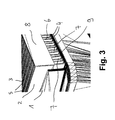
- die Anordnung gemäß
Fig. 1 in einer detaillierten Ansicht. -
Fig. 1 zeigt eine Anordnung, umfassend einen Ansaugstutzen 1 mit einem nicht gezeigten Lufteingang für eine Klimaanlage und ein Filterelement 2 mit einem Faltenbalg 3, der Faltentäler 4 und Faltenberge 5 aufweist, wobei das Filterelement 2 ein wasserabweisendes Filtermedium aufweist und wobei das Filterelement 2 den Lufteingang zumindest teilweise abdeckt. Konkret ist dargestellt, dass das Filterelement 2 den Lufteingang vollständig abdeckt. - Das Filterelement 2 reduziert die Luftmenge um etwa 5 - 30 % und ermöglicht eine Abscheidung von Schneeflocken im Größenbereich von 10 µm - 200 µm.
- Diese Anordnung ist ein einem nicht gezeigten Kraftfahrzeug verbaut. Der Faltenbalg 3 ist im eingebauten Zustand, nämlich wenn das Kraftfahrzeug auf einer nicht geneigten Ebene steht, gegen die Horizontale unter einem Winkel von 5 - 90° geneigt angeordnet, wobei das Filterelement 2 Mittel 6 für einen Wasserablauf aus den Faltentälern 4 aufweist.
- Jeweils auf einer Seite des Faltenbalgs 3 verlaufen Faltenkanten 7 einer zick-zack-Linie oder Wellenlinie folgend, wobei die Faltenkanten 7 auf mindestens einer Seite des Faltenbalgs 3 durch einen Kantenstreifen 8 gesäumt sind und wobei der Kantenstreifen 8 derart an den Faltenkanten 7 angeordnet oder ausgebildet ist, dass aus mindestens einem Faltental 4 Wasser abfließen kann.
- Am Grund mindestens eines Faltentals 4 ist eine Rinne 9 ausgebildet, die nicht vom Kantenstreifen 7 verschlossen ist. Insoweit sind die Mittel 6 für einen Wasserablauf als im Querschnitt V-förmige, vom Kantenstreifen 8 nicht verschlossene Öffnungen ausgestaltet.
- Das Filtermedium weist einen wasserabweisenden Vliesstoff auf, wobei das Filtermedium ein bis drei Schichten aufweist, wobei das Filtermedium und/ oder mindestens eine Schicht Fasern aus Polyethylentherephthtalat, Polypropylen, Polyamid oder Polyethylen aufweist oder wobei das Filtermedium und/ oder mindestens eine Schicht Mischungen aus den zuvor genannten Fasern aufweist. Konkret ist das Filtermedium aus Polypropylen gefertigt und weist ein Flächengewicht von 105 g/m2 auf. Das Filterelement 2 ist 195 mm lang und 110 mm breit. Der Faltenabstand beträgt 10 mm. Ein Faltenabstand zwischen 5 mm und 15 mm ist optimal.
- Der Ansaugstutzen 1 ist in einem Wasserkasten 10 des nicht gezeigten Kraftfahrzeugs angeordnet. Ein flexibler Kantenstreifen 8' erstreckt sich entgegen der Fahrtrichtung mit 55 mm Höhe und ist oben bündig. Der flexible Kantenstreifen 8 erstreckt sich in Fahrtrichtung mit 22 mm Höhe und ist ebenfalls oben mit dem Faltenbalg 3 bündig. Die Höhe der frei stehenden Faltentäler 4 beträgt 6 mm, dabei ragen die Faltentäler 4 in den Wasserkasten 10. Insoweit sind die Mittel 6 für einen Wasserablauf als im Querschnitt V-förmige, vom Kantenstreifen 8 nicht verschlossene Öffnungen ausgestaltet. Die Höhe dieser Öffnungen beträgt jeweils 6 mm.
Claims (9)
- Anordnung, umfassend einen Ansaugstutzen (1) mit einem Lufteingang für eine Klimaanlage und ein Filterelement (2) mit einem Faltenbalg (3), der Faltentäler (4) und Faltenberge (5) aufweist, wobei das Filterelement (2) ein wasserabweisendes Filtermedium aufweist und wobei das Filterelement (2) den Lufteingang zumindest teilweise abdeckt, dadurch gekennzeichnet, dass der Faltenbalg (3) gegen die Horizontale unter einem Winkel von 5° - 90°, bevorzugt unter einem Winkel von 15° - 85°, geneigt angeordnet ist, wobei das Filterelement (2) Mittel (6) für einen Wasserablauf aus den Faltentälern (4) aufweist.
- Anordnung nach Anspruch 1, dadurch gekennzeichnet, dass jeweils auf einer Seite des Faltenbalgs (3) Faltenkanten (7) einer zick-zack-Linie oder Wellenlinie folgend verlaufen, wobei die Faltenkanten (7) auf mindestens einer Seite des Faltenbalgs (3) durch einen Kantenstreifen (8) gesäumt sind und wobei der Kantenstreifen (8) derart an den Faltenkanten (7) angeordnet oder ausgebildet ist, dass aus mindestens einem Faltental (4) Wasser abfließen kann.
- Anordnung nach Anspruch 2, dadurch gekennzeichnet, dass am Grund mindestens eines Faltentals (4) eine Rinne (9) ausgebildet ist, die nicht vom Kantenstreifen (8) verschlossen ist.
- Anordnung nach Anspruch 2 oder 3, dadurch gekennzeichnet, dass die Mittel (6) als V-förmige Öffnungen ausgebildet sind.
- Anordnung nach einem der Ansprüche 2 bis 4, dadurch gekennzeichnet, dass der Kantenstreifen (8) als Spritzgussbauteil ausgestaltet ist.
- Anordnung nach einem der voranstehenden Ansprüche, dadurch gekennzeichnet, dass das Filtermedium einen wasserabweisenden Vliesstoff aufweist, wobei das Filtermedium ein bis drei Schichten aufweist, wobei das Filtermedium und/ oder mindestens eine Schicht Fasern aus Polyethylentherephthtalat, Polypropylen, Polyamid oder Polyethylen aufweist oder wobei das Filtermedium und/ oder mindestens eine Schicht Mischungen aus den zuvor genannten Fasern aufweist.
- Anordnung nach dem voranstehenden Anspruch, dadurch gekennzeichnet, dass der Vliesstoff eine Beschichtung aus Nanofasern aufweist.
- Anordnung nach einem der voranstehenden Ansprüche, dadurch gekennzeichnet, dass der Ansaugstutzen (1) in einem Wasserkasten (10) eines Kraftfahrzeugs angeordnet ist.
- Verwendung eines Filterelements (2) mit einem Faltenbalg (3), der Faltentäler (4) und Faltenberge (5) aufweist, wobei das Filterelement (2) ein wasserabweisendes Filtermedium aufweist, wobei das Filterelement (2) Mittel (6) für einen Wasserablauf aus den Faltentälern (4) aufweist, wobei jeweils auf einer Seite des Faltenbalgs (3) Faltenkanten (7) einer zick-zack-Linie oder Wellenlinie folgend verlaufen, wobei die Faltenkanten (7) auf mindestens einer Seite des Faltenbalgs (3) durch einen Kantenstreifen (8) gesäumt sind, wobei der Kantenstreifen (8) derart an den Faltenkanten (7) angeordnet oder ausgebildet ist, dass aus mindestens einem Faltental (4) Wasser abfließen kann, wobei am Grund mindestens eines Faltentals (4) eine Rinne (9) ausgebildet ist, die nicht vom Kantenstreifen (8) verschlossen ist, und wobei die Mittel (6) als V-förmige Öffnungen ausgebildet sind zur Filterung der Zuluft einer Klimaanlage.
Priority Applications (4)
| Application Number | Priority Date | Filing Date | Title |
|---|---|---|---|
| EP14190869.9A EP3015297B2 (de) | 2014-10-29 | 2014-10-29 | Anordnung mit einem Filterelement |
| BR102015026572A BR102015026572A2 (pt) | 2014-10-29 | 2015-10-20 | disposição com um elemento de filtro |
| US14/923,499 US9844999B2 (en) | 2014-10-29 | 2015-10-27 | Assembly with a filter element |
| CN201510711147.6A CN105561698B (zh) | 2014-10-29 | 2015-10-28 | 具有过滤元件的配置组件 |
Applications Claiming Priority (1)
| Application Number | Priority Date | Filing Date | Title |
|---|---|---|---|
| EP14190869.9A EP3015297B2 (de) | 2014-10-29 | 2014-10-29 | Anordnung mit einem Filterelement |
Publications (3)
| Publication Number | Publication Date |
|---|---|
| EP3015297A1 true EP3015297A1 (de) | 2016-05-04 |
| EP3015297B1 EP3015297B1 (de) | 2018-12-05 |
| EP3015297B2 EP3015297B2 (de) | 2022-09-14 |
Family
ID=51862128
Family Applications (1)
| Application Number | Title | Priority Date | Filing Date |
|---|---|---|---|
| EP14190869.9A Active EP3015297B2 (de) | 2014-10-29 | 2014-10-29 | Anordnung mit einem Filterelement |
Country Status (4)
| Country | Link |
|---|---|
| US (1) | US9844999B2 (de) |
| EP (1) | EP3015297B2 (de) |
| CN (1) | CN105561698B (de) |
| BR (1) | BR102015026572A2 (de) |
Cited By (1)
| Publication number | Priority date | Publication date | Assignee | Title |
|---|---|---|---|---|
| DE102016209264A1 (de) * | 2016-05-27 | 2017-11-30 | Volkswagen Aktiengesellschaft | Anordnung zur Versorgung eines eine Belüftungsvorrichtung aufweisenden Klimagerätes eines Fahrzeugs mit Frischluft sowie Fahrzeug |
Families Citing this family (1)
| Publication number | Priority date | Publication date | Assignee | Title |
|---|---|---|---|---|
| US20240383316A1 (en) * | 2023-05-20 | 2024-11-21 | Nathan Johnston | Dust reduction unit for recreational vehicles |
Citations (5)
| Publication number | Priority date | Publication date | Assignee | Title |
|---|---|---|---|---|
| DE4327368A1 (de) * | 1993-08-14 | 1995-02-16 | Minnesota Mining & Mfg | Filter zum Filtern einer Fluidströmung |
| DE19715755C1 (de) * | 1997-04-16 | 1998-10-29 | Freudenberg Carl Fa | Filter |
| JPH115429A (ja) * | 1997-06-17 | 1999-01-12 | Calsonic Corp | 自動車用空気調和装置のフィルター |
| DE602005003958T2 (de) | 2004-07-09 | 2008-12-04 | 3M Innovative Properties Co., Saint Paul | Verfahren zum bilden von selbsttragenden plissierten filtermedien |
| DE102012012669A1 (de) * | 2012-06-23 | 2013-01-03 | Daimler Ag | Luftfilter für eine Belüftungseinrichtung eines Fahrzeugs und Luftfilteranordnung |
Family Cites Families (15)
| Publication number | Priority date | Publication date | Assignee | Title |
|---|---|---|---|---|
| CH594437A5 (de) * | 1975-12-04 | 1978-01-13 | Erhard Charles Andreae | |
| JPS605416U (ja) * | 1983-06-24 | 1985-01-16 | ミドリ安全株式会社 | エア−クリ−ナ用フイルタ |
| FR2568138B1 (fr) * | 1984-07-25 | 1986-11-14 | Are Sarl | Cartouche de filtration a surface externe en nids d'abeilles et procede de realisation |
| FR2673909B1 (fr) * | 1991-03-15 | 1993-12-24 | Buchberg Akiva | Methode d'emballage a partir de bandes formees de feuilles souples plissees en plis egaux fixes entre eux a leurs extremites. |
| DE4142019A1 (de) * | 1991-12-19 | 1993-06-24 | Behr Gmbh & Co | Wellrippe fuer flachrohrwaermetauscher |
| SE469925B (sv) * | 1992-02-21 | 1993-10-11 | Gibeck Respiration Ab | Filteranordning för anslutning till en persons andningsorgan innefattande ett hölje som innesluter ett fukt-värmeväxlande material och ett bakterieupptagande filter, som består av ett veckat, luftgenomträngligt material |
| US5679122A (en) * | 1993-08-14 | 1997-10-21 | Minnesota Mining & Manufacturing Company | Filter for the filtration of a fluid flow |
| GB9908099D0 (en) * | 1999-04-12 | 1999-06-02 | Gay Geoffrey N W | Air cleaning collection device |
| DE10109474C1 (de) | 2001-02-28 | 2002-06-20 | Sandler Helmut Helsa Werke | Filtermaterialien mit bipolarer Beschichtung |
| US8303693B2 (en) † | 2007-04-26 | 2012-11-06 | The Hong Kong Polytechnic University | Nanofiber filter facemasks and cabin filters |
| FR2924471B1 (fr) * | 2007-11-30 | 2013-11-01 | Eurocopter France | Entree d'air d'un turbomoteur pourvue d'un systeme de filtration controle |
| PL2304326T3 (pl) * | 2008-01-14 | 2019-05-31 | Core Energy Recovery Solutions Inc | Membranowe wkłady harmonijkowe-krzyżowe i sposób wytwarzania membranowych wkładów harmonijkowych-krzyżowych |
| DE102010026101B4 (de) † | 2010-07-05 | 2018-06-28 | Audi Ag | Heizungs- und Klimatisierungseinrichtung |
| DE102011111368A1 (de) † | 2011-08-29 | 2013-02-28 | Mann+Hummel Gmbh | Filterelement |
| EP2634023B1 (de) † | 2012-03-01 | 2017-08-02 | Valeo Klimasysteme GmbH | Lufteinlassvorrichtung für ein Belüftungssystem eines Fahrzeuginnenraumes |
-
2014
- 2014-10-29 EP EP14190869.9A patent/EP3015297B2/de active Active
-
2015
- 2015-10-20 BR BR102015026572A patent/BR102015026572A2/pt not_active Application Discontinuation
- 2015-10-27 US US14/923,499 patent/US9844999B2/en not_active Expired - Fee Related
- 2015-10-28 CN CN201510711147.6A patent/CN105561698B/zh active Active
Patent Citations (5)
| Publication number | Priority date | Publication date | Assignee | Title |
|---|---|---|---|---|
| DE4327368A1 (de) * | 1993-08-14 | 1995-02-16 | Minnesota Mining & Mfg | Filter zum Filtern einer Fluidströmung |
| DE19715755C1 (de) * | 1997-04-16 | 1998-10-29 | Freudenberg Carl Fa | Filter |
| JPH115429A (ja) * | 1997-06-17 | 1999-01-12 | Calsonic Corp | 自動車用空気調和装置のフィルター |
| DE602005003958T2 (de) | 2004-07-09 | 2008-12-04 | 3M Innovative Properties Co., Saint Paul | Verfahren zum bilden von selbsttragenden plissierten filtermedien |
| DE102012012669A1 (de) * | 2012-06-23 | 2013-01-03 | Daimler Ag | Luftfilter für eine Belüftungseinrichtung eines Fahrzeugs und Luftfilteranordnung |
Cited By (2)
| Publication number | Priority date | Publication date | Assignee | Title |
|---|---|---|---|---|
| DE102016209264A1 (de) * | 2016-05-27 | 2017-11-30 | Volkswagen Aktiengesellschaft | Anordnung zur Versorgung eines eine Belüftungsvorrichtung aufweisenden Klimagerätes eines Fahrzeugs mit Frischluft sowie Fahrzeug |
| DE102016209264B4 (de) | 2016-05-27 | 2022-10-06 | Volkswagen Aktiengesellschaft | Anordnung zur Versorgung eines eine Belüftungsvorrichtung aufweisenden Klimagerätes eines Fahrzeugs mit Frischluft sowie Fahrzeug |
Also Published As
| Publication number | Publication date |
|---|---|
| CN105561698B (zh) | 2017-12-12 |
| BR102015026572A2 (pt) | 2016-06-14 |
| CN105561698A (zh) | 2016-05-11 |
| US9844999B2 (en) | 2017-12-19 |
| EP3015297B1 (de) | 2018-12-05 |
| EP3015297B2 (de) | 2022-09-14 |
| US20160121698A1 (en) | 2016-05-05 |
Similar Documents
| Publication | Publication Date | Title |
|---|---|---|
| EP3570962B1 (de) | Umgebungsluftreinigungsvorrichtung und strassenfahrzeug mit umgebungsluftreinigungsvorrichtung | |
| DE112012003579B4 (de) | lnnenraumfilterelement und Klimaanlage oder Innenraumzuluftanlage eines Kraftfahrzeugs umfassend ein Filterelement | |
| DE102009025393B4 (de) | 3-stufiger Kraftstofffilter | |
| EP2098275B1 (de) | Filter | |
| DE112013003032B4 (de) | Innenraumfilter und Filterelement für einen Innenraumfilter | |
| DE102012023856A1 (de) | Ansaugmodul eines Luftansaugtrakts einer Brennkraftmaschine | |
| DE102012100884A1 (de) | Feuchtigkeits-Ableitungsvorrichtung und -Verfahren für ein Lufteinlasssystem | |
| DE102015007968A1 (de) | Filterelement und Verfahren zum Herstellen desselben | |
| DE102009055192A1 (de) | Filtervorrichtung zum Abtrennen von Lack-Overspray | |
| DE102016009603A1 (de) | Filterelement und Filteranordnung | |
| DE102013017183A1 (de) | Luftkanal für ein Fahrzeug | |
| DE102020113615B4 (de) | Filterelement, Innenraumluftfilter, Filteranordnung und Verwendung eines Filterelements | |
| DE102016001486A1 (de) | Vorrichtung zum Filtrieren von verunreinigter Luft | |
| DE102017011876A1 (de) | Luftfilter mit integriertem Schneeschutz und Filterelement | |
| DE2807159A1 (de) | Vorrichtung zum trennen von stoffen unterschiedlicher wichte aus medien, insbesondere staubpartikeln u.a. aus atmosphaerischer luft | |
| EP3015297B1 (de) | Anordnung mit einem Filterelement | |
| DE102014017785B4 (de) | Filteranordnung und Verwendung eines Filterelements | |
| DE102014000914A1 (de) | Filterelement | |
| EP1978158A1 (de) | Verfahren zur Strassenreinigung und Strassenreinigungsfahrzeug | |
| DE112018004396T5 (de) | Austragsverarbeitungseinrichtung und verfahren für ein fahrzeugdruckluftbremsenfüllsystem | |
| EP4400197B1 (de) | Lufteintritts- oder luftaustrittsfilter für ein schaltschrankgehäuse und eine entsprechende schaltschrankanordnung | |
| DE102015208104B3 (de) | Vorrichtung zum Filtern von Luft | |
| WO2023061943A1 (de) | Filterelement und filtersystem | |
| EP1970114B1 (de) | Filter, insbesondere Luftfilter, mit Flüssigkeitssammelvorrichtung | |
| DE10135778A1 (de) | Kraftfahrzeug |
Legal Events
| Date | Code | Title | Description |
|---|---|---|---|
| PUAI | Public reference made under article 153(3) epc to a published international application that has entered the european phase |
Free format text: ORIGINAL CODE: 0009012 |
|
| AK | Designated contracting states |
Kind code of ref document: A1 Designated state(s): AL AT BE BG CH CY CZ DE DK EE ES FI FR GB GR HR HU IE IS IT LI LT LU LV MC MK MT NL NO PL PT RO RS SE SI SK SM TR |
|
| AX | Request for extension of the european patent |
Extension state: BA ME |
|
| STAA | Information on the status of an ep patent application or granted ep patent |
Free format text: STATUS: REQUEST FOR EXAMINATION WAS MADE |
|
| 17P | Request for examination filed |
Effective date: 20161102 |
|
| RBV | Designated contracting states (corrected) |
Designated state(s): AL AT BE BG CH CY CZ DE DK EE ES FI FR GB GR HR HU IE IS IT LI LT LU LV MC MK MT NL NO PL PT RO RS SE SI SK SM TR |
|
| RIN1 | Information on inventor provided before grant (corrected) |
Inventor name: KRAUSE, MARTIN |
|
| STAA | Information on the status of an ep patent application or granted ep patent |
Free format text: STATUS: EXAMINATION IS IN PROGRESS |
|
| 17Q | First examination report despatched |
Effective date: 20180309 |
|
| GRAP | Despatch of communication of intention to grant a patent |
Free format text: ORIGINAL CODE: EPIDOSNIGR1 |
|
| STAA | Information on the status of an ep patent application or granted ep patent |
Free format text: STATUS: GRANT OF PATENT IS INTENDED |
|
| RIC1 | Information provided on ipc code assigned before grant |
Ipc: B01D 46/10 20060101ALI20180718BHEP Ipc: B01D 46/00 20060101ALI20180718BHEP Ipc: B01D 46/52 20060101ALI20180718BHEP Ipc: B60H 3/06 20060101AFI20180718BHEP |
|
| INTG | Intention to grant announced |
Effective date: 20180814 |
|
| GRAS | Grant fee paid |
Free format text: ORIGINAL CODE: EPIDOSNIGR3 |
|
| GRAA | (expected) grant |
Free format text: ORIGINAL CODE: 0009210 |
|
| STAA | Information on the status of an ep patent application or granted ep patent |
Free format text: STATUS: THE PATENT HAS BEEN GRANTED |
|
| AK | Designated contracting states |
Kind code of ref document: B1 Designated state(s): AL AT BE BG CH CY CZ DE DK EE ES FI FR GB GR HR HU IE IS IT LI LT LU LV MC MK MT NL NO PL PT RO RS SE SI SK SM TR |
|
| REG | Reference to a national code |
Ref country code: GB Ref legal event code: FG4D Free format text: NOT ENGLISH |
|
| REG | Reference to a national code |
Ref country code: CH Ref legal event code: EP |
|
| REG | Reference to a national code |
Ref country code: AT Ref legal event code: REF Ref document number: 1072570 Country of ref document: AT Kind code of ref document: T Effective date: 20181215 |
|
| REG | Reference to a national code |
Ref country code: IE Ref legal event code: FG4D Free format text: LANGUAGE OF EP DOCUMENT: GERMAN |
|
| REG | Reference to a national code |
Ref country code: DE Ref legal event code: R096 Ref document number: 502014010257 Country of ref document: DE |
|
| REG | Reference to a national code |
Ref country code: NL Ref legal event code: MP Effective date: 20181205 |
|
| REG | Reference to a national code |
Ref country code: LT Ref legal event code: MG4D |
|
| PG25 | Lapsed in a contracting state [announced via postgrant information from national office to epo] |
Ref country code: ES Free format text: LAPSE BECAUSE OF FAILURE TO SUBMIT A TRANSLATION OF THE DESCRIPTION OR TO PAY THE FEE WITHIN THE PRESCRIBED TIME-LIMIT Effective date: 20181205 Ref country code: NO Free format text: LAPSE BECAUSE OF FAILURE TO SUBMIT A TRANSLATION OF THE DESCRIPTION OR TO PAY THE FEE WITHIN THE PRESCRIBED TIME-LIMIT Effective date: 20190305 Ref country code: BG Free format text: LAPSE BECAUSE OF FAILURE TO SUBMIT A TRANSLATION OF THE DESCRIPTION OR TO PAY THE FEE WITHIN THE PRESCRIBED TIME-LIMIT Effective date: 20190305 Ref country code: FI Free format text: LAPSE BECAUSE OF FAILURE TO SUBMIT A TRANSLATION OF THE DESCRIPTION OR TO PAY THE FEE WITHIN THE PRESCRIBED TIME-LIMIT Effective date: 20181205 Ref country code: LT Free format text: LAPSE BECAUSE OF FAILURE TO SUBMIT A TRANSLATION OF THE DESCRIPTION OR TO PAY THE FEE WITHIN THE PRESCRIBED TIME-LIMIT Effective date: 20181205 Ref country code: LV Free format text: LAPSE BECAUSE OF FAILURE TO SUBMIT A TRANSLATION OF THE DESCRIPTION OR TO PAY THE FEE WITHIN THE PRESCRIBED TIME-LIMIT Effective date: 20181205 Ref country code: HR Free format text: LAPSE BECAUSE OF FAILURE TO SUBMIT A TRANSLATION OF THE DESCRIPTION OR TO PAY THE FEE WITHIN THE PRESCRIBED TIME-LIMIT Effective date: 20181205 |
|
| PG25 | Lapsed in a contracting state [announced via postgrant information from national office to epo] |
Ref country code: SE Free format text: LAPSE BECAUSE OF FAILURE TO SUBMIT A TRANSLATION OF THE DESCRIPTION OR TO PAY THE FEE WITHIN THE PRESCRIBED TIME-LIMIT Effective date: 20181205 Ref country code: RS Free format text: LAPSE BECAUSE OF FAILURE TO SUBMIT A TRANSLATION OF THE DESCRIPTION OR TO PAY THE FEE WITHIN THE PRESCRIBED TIME-LIMIT Effective date: 20181205 Ref country code: AL Free format text: LAPSE BECAUSE OF FAILURE TO SUBMIT A TRANSLATION OF THE DESCRIPTION OR TO PAY THE FEE WITHIN THE PRESCRIBED TIME-LIMIT Effective date: 20181205 Ref country code: GR Free format text: LAPSE BECAUSE OF FAILURE TO SUBMIT A TRANSLATION OF THE DESCRIPTION OR TO PAY THE FEE WITHIN THE PRESCRIBED TIME-LIMIT Effective date: 20190306 |
|
| PG25 | Lapsed in a contracting state [announced via postgrant information from national office to epo] |
Ref country code: NL Free format text: LAPSE BECAUSE OF FAILURE TO SUBMIT A TRANSLATION OF THE DESCRIPTION OR TO PAY THE FEE WITHIN THE PRESCRIBED TIME-LIMIT Effective date: 20181205 |
|
| PG25 | Lapsed in a contracting state [announced via postgrant information from national office to epo] |
Ref country code: PT Free format text: LAPSE BECAUSE OF FAILURE TO SUBMIT A TRANSLATION OF THE DESCRIPTION OR TO PAY THE FEE WITHIN THE PRESCRIBED TIME-LIMIT Effective date: 20190405 Ref country code: PL Free format text: LAPSE BECAUSE OF FAILURE TO SUBMIT A TRANSLATION OF THE DESCRIPTION OR TO PAY THE FEE WITHIN THE PRESCRIBED TIME-LIMIT Effective date: 20181205 Ref country code: CZ Free format text: LAPSE BECAUSE OF FAILURE TO SUBMIT A TRANSLATION OF THE DESCRIPTION OR TO PAY THE FEE WITHIN THE PRESCRIBED TIME-LIMIT Effective date: 20181205 |
|
| PG25 | Lapsed in a contracting state [announced via postgrant information from national office to epo] |
Ref country code: IS Free format text: LAPSE BECAUSE OF FAILURE TO SUBMIT A TRANSLATION OF THE DESCRIPTION OR TO PAY THE FEE WITHIN THE PRESCRIBED TIME-LIMIT Effective date: 20190405 Ref country code: SM Free format text: LAPSE BECAUSE OF FAILURE TO SUBMIT A TRANSLATION OF THE DESCRIPTION OR TO PAY THE FEE WITHIN THE PRESCRIBED TIME-LIMIT Effective date: 20181205 Ref country code: EE Free format text: LAPSE BECAUSE OF FAILURE TO SUBMIT A TRANSLATION OF THE DESCRIPTION OR TO PAY THE FEE WITHIN THE PRESCRIBED TIME-LIMIT Effective date: 20181205 Ref country code: RO Free format text: LAPSE BECAUSE OF FAILURE TO SUBMIT A TRANSLATION OF THE DESCRIPTION OR TO PAY THE FEE WITHIN THE PRESCRIBED TIME-LIMIT Effective date: 20181205 Ref country code: SK Free format text: LAPSE BECAUSE OF FAILURE TO SUBMIT A TRANSLATION OF THE DESCRIPTION OR TO PAY THE FEE WITHIN THE PRESCRIBED TIME-LIMIT Effective date: 20181205 |
|
| REG | Reference to a national code |
Ref country code: DE Ref legal event code: R026 Ref document number: 502014010257 Country of ref document: DE |
|
| PLAX | Notice of opposition and request to file observation + time limit sent |
Free format text: ORIGINAL CODE: EPIDOSNOBS2 |
|
| PLBI | Opposition filed |
Free format text: ORIGINAL CODE: 0009260 |
|
| 26 | Opposition filed |
Opponent name: MANN + HUMMEL GMBH Effective date: 20190905 |
|
| PG25 | Lapsed in a contracting state [announced via postgrant information from national office to epo] |
Ref country code: DK Free format text: LAPSE BECAUSE OF FAILURE TO SUBMIT A TRANSLATION OF THE DESCRIPTION OR TO PAY THE FEE WITHIN THE PRESCRIBED TIME-LIMIT Effective date: 20181205 Ref country code: SI Free format text: LAPSE BECAUSE OF FAILURE TO SUBMIT A TRANSLATION OF THE DESCRIPTION OR TO PAY THE FEE WITHIN THE PRESCRIBED TIME-LIMIT Effective date: 20181205 |
|
| PLBB | Reply of patent proprietor to notice(s) of opposition received |
Free format text: ORIGINAL CODE: EPIDOSNOBS3 |
|
| PG25 | Lapsed in a contracting state [announced via postgrant information from national office to epo] |
Ref country code: TR Free format text: LAPSE BECAUSE OF FAILURE TO SUBMIT A TRANSLATION OF THE DESCRIPTION OR TO PAY THE FEE WITHIN THE PRESCRIBED TIME-LIMIT Effective date: 20181205 |
|
| PG25 | Lapsed in a contracting state [announced via postgrant information from national office to epo] |
Ref country code: MC Free format text: LAPSE BECAUSE OF FAILURE TO SUBMIT A TRANSLATION OF THE DESCRIPTION OR TO PAY THE FEE WITHIN THE PRESCRIBED TIME-LIMIT Effective date: 20181205 |
|
| REG | Reference to a national code |
Ref country code: CH Ref legal event code: PL |
|
| PG25 | Lapsed in a contracting state [announced via postgrant information from national office to epo] |
Ref country code: LI Free format text: LAPSE BECAUSE OF NON-PAYMENT OF DUE FEES Effective date: 20191031 Ref country code: LU Free format text: LAPSE BECAUSE OF NON-PAYMENT OF DUE FEES Effective date: 20191029 Ref country code: CH Free format text: LAPSE BECAUSE OF NON-PAYMENT OF DUE FEES Effective date: 20191031 |
|
| REG | Reference to a national code |
Ref country code: BE Ref legal event code: MM Effective date: 20191031 |
|
| PG25 | Lapsed in a contracting state [announced via postgrant information from national office to epo] |
Ref country code: BE Free format text: LAPSE BECAUSE OF NON-PAYMENT OF DUE FEES Effective date: 20191031 |
|
| PG25 | Lapsed in a contracting state [announced via postgrant information from national office to epo] |
Ref country code: IE Free format text: LAPSE BECAUSE OF NON-PAYMENT OF DUE FEES Effective date: 20191029 |
|
| REG | Reference to a national code |
Ref country code: AT Ref legal event code: MM01 Ref document number: 1072570 Country of ref document: AT Kind code of ref document: T Effective date: 20191029 |
|
| PLBP | Opposition withdrawn |
Free format text: ORIGINAL CODE: 0009264 |
|
| PG25 | Lapsed in a contracting state [announced via postgrant information from national office to epo] |
Ref country code: AT Free format text: LAPSE BECAUSE OF NON-PAYMENT OF DUE FEES Effective date: 20191029 |
|
| PGFP | Annual fee paid to national office [announced via postgrant information from national office to epo] |
Ref country code: GB Payment date: 20201023 Year of fee payment: 7 Ref country code: IT Payment date: 20201030 Year of fee payment: 7 Ref country code: FR Payment date: 20201023 Year of fee payment: 7 |
|
| PLAB | Opposition data, opponent's data or that of the opponent's representative modified |
Free format text: ORIGINAL CODE: 0009299OPPO |
|
| PG25 | Lapsed in a contracting state [announced via postgrant information from national office to epo] |
Ref country code: CY Free format text: LAPSE BECAUSE OF FAILURE TO SUBMIT A TRANSLATION OF THE DESCRIPTION OR TO PAY THE FEE WITHIN THE PRESCRIBED TIME-LIMIT Effective date: 20181205 |
|
| PG25 | Lapsed in a contracting state [announced via postgrant information from national office to epo] |
Ref country code: HU Free format text: LAPSE BECAUSE OF FAILURE TO SUBMIT A TRANSLATION OF THE DESCRIPTION OR TO PAY THE FEE WITHIN THE PRESCRIBED TIME-LIMIT; INVALID AB INITIO Effective date: 20141029 Ref country code: MT Free format text: LAPSE BECAUSE OF FAILURE TO SUBMIT A TRANSLATION OF THE DESCRIPTION OR TO PAY THE FEE WITHIN THE PRESCRIBED TIME-LIMIT Effective date: 20181205 |
|
| GBPC | Gb: european patent ceased through non-payment of renewal fee |
Effective date: 20211029 |
|
| PG25 | Lapsed in a contracting state [announced via postgrant information from national office to epo] |
Ref country code: MK Free format text: LAPSE BECAUSE OF FAILURE TO SUBMIT A TRANSLATION OF THE DESCRIPTION OR TO PAY THE FEE WITHIN THE PRESCRIBED TIME-LIMIT Effective date: 20181205 |
|
| PG25 | Lapsed in a contracting state [announced via postgrant information from national office to epo] |
Ref country code: GB Free format text: LAPSE BECAUSE OF NON-PAYMENT OF DUE FEES Effective date: 20211029 |
|
| PUAH | Patent maintained in amended form |
Free format text: ORIGINAL CODE: 0009272 |
|
| STAA | Information on the status of an ep patent application or granted ep patent |
Free format text: STATUS: PATENT MAINTAINED AS AMENDED |
|
| 27A | Patent maintained in amended form |
Effective date: 20220914 |
|
| AK | Designated contracting states |
Kind code of ref document: B2 Designated state(s): AL AT BE BG CH CY CZ DE DK EE ES FI FR GB GR HR HU IE IS IT LI LT LU LV MC MK MT NL NO PL PT RO RS SE SI SK SM TR |
|
| REG | Reference to a national code |
Ref country code: DE Ref legal event code: R102 Ref document number: 502014010257 Country of ref document: DE |
|
| PG25 | Lapsed in a contracting state [announced via postgrant information from national office to epo] |
Ref country code: FR Free format text: LAPSE BECAUSE OF NON-PAYMENT OF DUE FEES Effective date: 20211031 |
|
| PG25 | Lapsed in a contracting state [announced via postgrant information from national office to epo] |
Ref country code: IT Free format text: LAPSE BECAUSE OF NON-PAYMENT OF DUE FEES Effective date: 20211029 |
|
| P01 | Opt-out of the competence of the unified patent court (upc) registered |
Effective date: 20230503 |
|
| PGFP | Annual fee paid to national office [announced via postgrant information from national office to epo] |
Ref country code: DE Payment date: 20241018 Year of fee payment: 11 |