EP3015251B1 - Three-dimensional shaped body and support formation method - Google Patents
Three-dimensional shaped body and support formation method Download PDFInfo
- Publication number
- EP3015251B1 EP3015251B1 EP14816566.5A EP14816566A EP3015251B1 EP 3015251 B1 EP3015251 B1 EP 3015251B1 EP 14816566 A EP14816566 A EP 14816566A EP 3015251 B1 EP3015251 B1 EP 3015251B1
- Authority
- EP
- European Patent Office
- Prior art keywords
- support
- modeled
- dimensional
- article
- powder
- Prior art date
- Legal status (The legal status is an assumption and is not a legal conclusion. Google has not performed a legal analysis and makes no representation as to the accuracy of the status listed.)
- Active
Links
Images


Classifications
-
- B—PERFORMING OPERATIONS; TRANSPORTING
- B29—WORKING OF PLASTICS; WORKING OF SUBSTANCES IN A PLASTIC STATE IN GENERAL
- B29C—SHAPING OR JOINING OF PLASTICS; SHAPING OF MATERIAL IN A PLASTIC STATE, NOT OTHERWISE PROVIDED FOR; AFTER-TREATMENT OF THE SHAPED PRODUCTS, e.g. REPAIRING
- B29C64/00—Additive manufacturing, i.e. manufacturing of three-dimensional [3D] objects by additive deposition, additive agglomeration or additive layering, e.g. by 3D printing, stereolithography or selective laser sintering
- B29C64/40—Structures for supporting 3D objects during manufacture and intended to be sacrificed after completion thereof
-
- B—PERFORMING OPERATIONS; TRANSPORTING
- B22—CASTING; POWDER METALLURGY
- B22F—WORKING METALLIC POWDER; MANUFACTURE OF ARTICLES FROM METALLIC POWDER; MAKING METALLIC POWDER; APPARATUS OR DEVICES SPECIALLY ADAPTED FOR METALLIC POWDER
- B22F10/00—Additive manufacturing of workpieces or articles from metallic powder
- B22F10/10—Formation of a green body
- B22F10/14—Formation of a green body by jetting of binder onto a bed of metal powder
-
- B—PERFORMING OPERATIONS; TRANSPORTING
- B22—CASTING; POWDER METALLURGY
- B22F—WORKING METALLIC POWDER; MANUFACTURE OF ARTICLES FROM METALLIC POWDER; MAKING METALLIC POWDER; APPARATUS OR DEVICES SPECIALLY ADAPTED FOR METALLIC POWDER
- B22F10/00—Additive manufacturing of workpieces or articles from metallic powder
- B22F10/20—Direct sintering or melting
- B22F10/28—Powder bed fusion, e.g. selective laser melting [SLM] or electron beam melting [EBM]
-
- B—PERFORMING OPERATIONS; TRANSPORTING
- B22—CASTING; POWDER METALLURGY
- B22F—WORKING METALLIC POWDER; MANUFACTURE OF ARTICLES FROM METALLIC POWDER; MAKING METALLIC POWDER; APPARATUS OR DEVICES SPECIALLY ADAPTED FOR METALLIC POWDER
- B22F10/00—Additive manufacturing of workpieces or articles from metallic powder
- B22F10/40—Structures for supporting workpieces or articles during manufacture and removed afterwards
- B22F10/47—Structures for supporting workpieces or articles during manufacture and removed afterwards characterised by structural features
-
- B—PERFORMING OPERATIONS; TRANSPORTING
- B29—WORKING OF PLASTICS; WORKING OF SUBSTANCES IN A PLASTIC STATE IN GENERAL
- B29C—SHAPING OR JOINING OF PLASTICS; SHAPING OF MATERIAL IN A PLASTIC STATE, NOT OTHERWISE PROVIDED FOR; AFTER-TREATMENT OF THE SHAPED PRODUCTS, e.g. REPAIRING
- B29C64/00—Additive manufacturing, i.e. manufacturing of three-dimensional [3D] objects by additive deposition, additive agglomeration or additive layering, e.g. by 3D printing, stereolithography or selective laser sintering
- B29C64/10—Processes of additive manufacturing
- B29C64/141—Processes of additive manufacturing using only solid materials
- B29C64/153—Processes of additive manufacturing using only solid materials using layers of powder being selectively joined, e.g. by selective laser sintering or melting
-
- B—PERFORMING OPERATIONS; TRANSPORTING
- B29—WORKING OF PLASTICS; WORKING OF SUBSTANCES IN A PLASTIC STATE IN GENERAL
- B29C—SHAPING OR JOINING OF PLASTICS; SHAPING OF MATERIAL IN A PLASTIC STATE, NOT OTHERWISE PROVIDED FOR; AFTER-TREATMENT OF THE SHAPED PRODUCTS, e.g. REPAIRING
- B29C64/00—Additive manufacturing, i.e. manufacturing of three-dimensional [3D] objects by additive deposition, additive agglomeration or additive layering, e.g. by 3D printing, stereolithography or selective laser sintering
- B29C64/10—Processes of additive manufacturing
- B29C64/165—Processes of additive manufacturing using a combination of solid and fluid materials, e.g. a powder selectively bound by a liquid binder, catalyst, inhibitor or energy absorber
-
- B—PERFORMING OPERATIONS; TRANSPORTING
- B33—ADDITIVE MANUFACTURING TECHNOLOGY
- B33Y—ADDITIVE MANUFACTURING, i.e. MANUFACTURING OF THREE-DIMENSIONAL [3-D] OBJECTS BY ADDITIVE DEPOSITION, ADDITIVE AGGLOMERATION OR ADDITIVE LAYERING, e.g. BY 3-D PRINTING, STEREOLITHOGRAPHY OR SELECTIVE LASER SINTERING
- B33Y10/00—Processes of additive manufacturing
-
- B—PERFORMING OPERATIONS; TRANSPORTING
- B33—ADDITIVE MANUFACTURING TECHNOLOGY
- B33Y—ADDITIVE MANUFACTURING, i.e. MANUFACTURING OF THREE-DIMENSIONAL [3-D] OBJECTS BY ADDITIVE DEPOSITION, ADDITIVE AGGLOMERATION OR ADDITIVE LAYERING, e.g. BY 3-D PRINTING, STEREOLITHOGRAPHY OR SELECTIVE LASER SINTERING
- B33Y30/00—Apparatus for additive manufacturing; Details thereof or accessories therefor
-
- B—PERFORMING OPERATIONS; TRANSPORTING
- B33—ADDITIVE MANUFACTURING TECHNOLOGY
- B33Y—ADDITIVE MANUFACTURING, i.e. MANUFACTURING OF THREE-DIMENSIONAL [3-D] OBJECTS BY ADDITIVE DEPOSITION, ADDITIVE AGGLOMERATION OR ADDITIVE LAYERING, e.g. BY 3-D PRINTING, STEREOLITHOGRAPHY OR SELECTIVE LASER SINTERING
- B33Y80/00—Products made by additive manufacturing
-
- B—PERFORMING OPERATIONS; TRANSPORTING
- B22—CASTING; POWDER METALLURGY
- B22F—WORKING METALLIC POWDER; MANUFACTURE OF ARTICLES FROM METALLIC POWDER; MAKING METALLIC POWDER; APPARATUS OR DEVICES SPECIALLY ADAPTED FOR METALLIC POWDER
- B22F10/00—Additive manufacturing of workpieces or articles from metallic powder
- B22F10/60—Treatment of workpieces or articles after build-up
- B22F10/68—Cleaning or washing
-
- Y—GENERAL TAGGING OF NEW TECHNOLOGICAL DEVELOPMENTS; GENERAL TAGGING OF CROSS-SECTIONAL TECHNOLOGIES SPANNING OVER SEVERAL SECTIONS OF THE IPC; TECHNICAL SUBJECTS COVERED BY FORMER USPC CROSS-REFERENCE ART COLLECTIONS [XRACs] AND DIGESTS
- Y02—TECHNOLOGIES OR APPLICATIONS FOR MITIGATION OR ADAPTATION AGAINST CLIMATE CHANGE
- Y02P—CLIMATE CHANGE MITIGATION TECHNOLOGIES IN THE PRODUCTION OR PROCESSING OF GOODS
- Y02P10/00—Technologies related to metal processing
- Y02P10/25—Process efficiency
Definitions
- the embodiment is to provide a three-dimensional modeled object and a support forming method capable of appropriately supporting a modeled article by a three-dimensional layering shaping technique.
- Reference Numerals 11a to 11c indicate modeled articles (models), Reference Numerals 21 and 22 indicate supports (support members), Reference Numerals 21a to 21c and the support 22 indicate connection portions of the supports 21 and 22, and Reference Numerals 4 indicates a fabrication table .
- the modeled article 11a is extracted, the modeled article 11b is extracted by removing the plate-shaped support 23b and the columnar supports 24b and 25b, and the modeled article 11a is extracted by removing the plate-shaped support 23a and the columnar supports 24a and 25a.
Description
- Embodiments described in the specification relate to a three-dimensional modeled object and a support forming method.
- In recent years, a three-dimensional layered modeling apparatus (a so-called 3D printer) that uses a laser beam lithography method, a powdery molding method, or a FDM method (Fused Deposition Modeling) has attracted attention.
- In the three-dimensional layered modeling apparatus, there is also known a method of shaping a support (a support member) that supports a modeled article so that the modeled article is not deformed when the modeled article (model) is formed. After the shaping process ends, the support is detached and discarded.
- Specifically, as the laser beam lithography method, for example, light (for example, a UV laser) which is controlled by a computer so as to obtain a desired pattern is selectively irradiated to a liquid surface of a liquid light curable resin (a fluid material) charged in a molding bath so as to cure the light curable resin. Further, light curable resin for one layer is supplied onto the cured layer, light is irradiated thereto again so as to cure the light curable resin, and the same process is repeated so as to form a desired modeled article.
- In the laser beam lithography method using such a liquid light curable resin, there is a concern that an undercut or a deformation may occur in, for example, an overhanging portion of a modeled article in that a portion cured by light cannot be supported by non-cured resin.
- Here, for example, in the three-dimensional layered modeling apparatus using the laser beam lithography method, since the fluid material is used in general, a support that supports the overhanging portion cured by the irradiation of light needs to be provided. Further, there is a need of providing a support in order to prevent a problem in which the modeled article is fixed to a fabrication table.
- In this manner, for example, in the three-dimensional layered modeling apparatus using the laser beam lithography method, the support is essential. However, since the support is an obstacle by nature, it is desirable to shape the support so that the support is small and is easily detachable.
- Further, in the three-dimensional layered modeling apparatus using the FDM method, for example, a string-shaped thermoplastic resin is melted by a heater inside a shaping head, the injection of the melted thermoplastic resin is controlled, and the resin is laminated and shaped by the elevation of a fabrication table.
- Even in the three-dimensional layered modeling apparatus using the FDM method, the modeled article is bent due to the weight thereof depending on the shape of the modeled article. For this reason, for example, there is a need of providing a material (a support material) for forming a support in addition to a material (a model material) of the modeled article.
- In the three-dimensional layered modeling apparatus using the FDM method, since the resin (string-shaped resin) can be generally used, the resin can be easily detached. However, for example, when the support is provided in a portion where a processing is difficult, there is a case in which the support is not easily detachable.
- Moreover, for example, an alkali solution is used to remove the support in a melted state. However, in this method, the operation is troublesome and the treatment of the alkali solution can involve danger.
- Incidentally, as a related art, various proposals are made as the support forming technique used when the modeled article is formed by the three-dimensional layered modeling apparatus .
-
- Patent Literature 1:
WO 09/136047 - Patent Literature 2:
JP H08-025487 A - Patent Literature 3:
JP 2000-309057 A - Patent Literature 4:
EP1486318 A2 - As described above, in the general three-dimensional layered modeling apparatus using the laser beam lithography method, the support is indispensably used. On the contrary, a three-dimensional layered modeling apparatus has been proposed, employing the laser beam lithography method, in which a non-fluid light curable resin is used.
- In the three-dimensional layered modeling apparatus using the laser beam lithography method using the non-fluid light curable resin, for example, when the modeled article is formed by the liquid light curable resin having a predetermined melting temperature, the light curable resin of the layer cured by the irradiation of light is maintained in a solid state at a temperature lower than a melting temperature, the light curable resin for one layer is supplied onto the top surface thereof, and the light curable resin is irradiated by light, thereby preventing a deformation such as an undercut in the modeled article. In addition, the solid state indicates a non-fluid state. For example, a wax state, a jelly state, and a sol state are included.
- However, in the three-dimensional layered modeling apparatus, for example, the light curable resin is used in the non-fluid state at the temperature lower than the melting temperature. However, for example, in a case where the modeled article has a large shape and a heavy weight and the modeled article is depressed even by the non-fluid light curable resin or a case where a deformation such as bending occurs due to the internal stress generated during a shaping process, a problem may arise.
- Moreover, when the post-process of the modeled article is automatically performed, the modeled article has an unstable shape, or the modeled articles are formed in an overlapping state in the height direction (the Z direction) similarly to a three-dimensional layered modeling apparatus using a powdery molding method to be described below, various problems may arise.
- That is, in the three-dimensional layered modeling apparatus using the powdery molding method, for example, the three-dimensional layered modeling apparatus using the powder sintering method, the powder melting method, or the powder bed and inkjet head 3D printing method, the powder resists the depression or the movement of the modeled article, and hence the support is not necessarily required in principle.
- However, for example, when the post-process of the modeled article is automatically performed, the modeled article has an unstable shape, or the modeled articles are formed in an overlapping state in the height direction, there is a concern of damage caused by the contacting of the modeled article s or the falling of the modeled article s when the powder (for example, sand, metallic powder, gypsum, starch, artificial bone, and plastic powder) is removed.
- Moreover, for example, if the modeled article has a large shape and a heavy weight or the modeled article s exist even when the post-process is not automatically performed, a worker who removes the powder needs to handle the modeled article while avoiding the damage and hence gets a large burden. Further, for example, when the modeled article has a large shape and a heavy weight, there is a concern that the modeled article may be depressed even by the non-fluid powder and a deformation such as bending may occur due to the internal stress generated during a shaping process.
- The embodiment is to provide a three-dimensional modeled object and a support forming method capable of appropriately supporting a modeled article by a three-dimensional layering shaping technique.
- In addition, in the specification, the three-dimensional modeled object indicates, for example, an entire object including the modeled article, the support, and the powder which is left while not being sintered or melted by a laser or a thermal head and to which the binding agent is not applied inside the fabrication tank of the three-dimensional layered modeling apparatus when the modeled article is formed by the powdery molding method. In this case, the desired modeled article can be obtained by removing, for example, the support and the powder from the three-dimensional modeled object formed inside the fabrication tank.
- Further, in the specification, the three-dimensional modeled object indicates, for example, an entire object including the modeled article , the support, and the non-fluid shaping material (if necessary, the fluid shaping material) such as light curable resin which is left while not being cured by light inside the fabrication tank of the three-dimensional layered modeling apparatus when the modeled article is formed by the non-fluid material such as light curable resin kept at a temperature lower than a melting temperature. In this case, for example, the desired modeled article can be obtained by removing the support and the non-fluid (and the fluid) shaping material from the three-dimensional modeled object formed inside the fabrication tank. The solution is provided by the object of claim 1 and by the method of claim 7.
- The three-dimensional modeled object and the support forming method disclosed herein have an effect that the modeled article can be formed while being appropriately supported. Further, according to the three-dimensional modeled object and the support forming method disclosed herein, for example, it is possible to reduce the damage of the modeled article when the post-process of the modeled article is automatically performed, the modeled article has an unstable shape, or the modeled articles are formed in an overlapping state in the height direction. Further, it is possible to reduce a burden on a worker who acquires the modeled article or removes the non-fluid material even when the post-process is not automatically performed.
-
-
Fig. 1 is a perspective view schematically illustrating an example of a three-dimensional layered modeling apparatus. -
Figs. 2A and 2B are diagrams illustrating an example of a three-dimensional modeled object. -
Figs. 3A to 3C are diagrams illustrating a first embodiment of the three-dimensional modeled object according to the invention. -
Figs. 4A to 4D are diagrams illustrating a modified example of the three-dimensional modeled object illustrated inFigs. 3A to 3C . -
Fig. 5 is a diagram illustrating another modified example of the three-dimensional modeled object illustrated inFigs. 3A to 3C . -
Figs. 6A to 6C are diagrams illustrating an example of a support shape used in the invention. -
Figs. 7A to 7C are diagrams illustrating a second embodiment of the three-dimensional modeled object according to the disclosure for the comparison with the related art. -
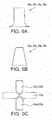
Figs. 8A to 8C are diagrams illustrating a modified example of a support shape obtained when forming a modeled article illustrated inFigs. 7A to 7C . -
Figs. 9A and 9B are diagrams illustrating another example of the modeled article used in the disclosure. -
Figs. 10A to 10C are diagrams illustrating a three-dimensional modeled object including the modeled article illustrated inFigs. 9A and 9B used for the comparison between the related art and the embodiment. -
Figs. 11A to 11C are diagrams illustrating a three-dimensional modeled object further including the modeled article used in the disclosure for the comparison between the related art and the embodiment. -
Fig. 12 is a diagram illustrating another example of a relation between a modeled article and a support. -
Fig. 13 is a diagram illustrating still another example of a relation between a modeled article and a support. - First, prior to the description of the embodiments of a three-dimensional modeled object and a support forming method according to the invention, an example of a three-dimensional layered modeling apparatus using a powdery molding method, a three-dimensional modeled object formed by the three-dimensional layered modeling apparatus, and a problem thereof will be described with reference to
Figs. 1 and2A and 2B . -
Fig. 1 is a perspective view schematically illustrating an example of a three-dimensional layered modeling apparatus and illustrating an example of a three-dimensionallayered modeling apparatus 100 that adopts a powdery molding method. - As illustrated in
Fig. 1 , a three-dimensionallayered modeling apparatus 100 includes acontrol computer 101, aprint head unit 102, arecoater unit 103, afabrication tank 104, anelevation device 105, a powdersupply hopper unit 106, acleaning unit 107, and achemical unit 108. Here, thefabrication tank 104 is provided with a fabrication table 141 which is controlled by theelevation device 105 in the Z-axis direction (the height direction). - When three-dimensional data (for example, STL data Standard Triangulated Language Data) is inputed to the
control computer 101, a slice process or an offset process and a bitmap conversion process are performed on the data so as to control the three-dimensionallayered modeling apparatus 100. - The
print head unit 102 applies (ejects) a binding agent (a binder) onto a surface of powder on the fabrication table 141 based on, for example, bitmap data so as to shape one layer. Further, theprint head unit 102 is provided with, for example, a plurality of inkjet heads each having a plurality of ejection nozzles. - Here, for example, the
print head unit 102 applies a binding agent onto the surface of the powder on the fabrication table 141 while moving theprinter head 121 in the X-axis direction (the left and right direction when viewed from the front side of the apparatus). - Further, when the application operation for one row in the X-axis direction ends, the
printer head 121 is moved in the Y-axis direction (the front to rear direction when viewed from the front side of the apparatus), and theprinter head 121 is moved again in the X-axis direction while applying the binding agent. By carrying out repeatedly such a process, one layer is shaped. - Further, the
printer head 121 may be configured as, for example, a line head having an entire length of the fabrication table 141 in the X-axis direction. In this case, the binding agent can be applied onto the entire surface of the powder on the fabrication table 141, that is, one layer shaping process can be performed only by the movement of theprinter head 121 in the Y-axis direction. - Then, when one layer shaping process on the entire surface of the powder on the fabrication table 141 ends, for example, the fabrication table 141 is moved downward in the Z-axis direction (the height direction) by the
elevation device 105 and a powder coating process for one layer is performed while therecoater unit 103 is moved in the Y-axis direction. - Here, the
recoater unit 103 includes, for example, arecoater hopper 131 and avibration blade 132. Therecoater hopper 131 stores powder supplied from the powdersupply hopper unit 106. - The
vibration blade 132 is operated when therecoater unit 103 moves in the Y-axis direction, and the powder is densely supplied onto the fabrication table 141 so as to be horizontal (in the X-Y plane) during the movement of therecoater unit 103. Further, theelevation device 105 is controlled so that the downward movement amount (the height) of the fabrication table 141 matches the thickness (the lamination pitch) of the powder coated by therecoater unit 103. - By repeating the above-described processes, a final modeled article is completed inside the
fabrication tank 104. That is, for example, a three-dimensional modeled object including a desired modeled article, a support, and a remaining powder to which a binding agent is not applied is formed inside thefabrication tank 104. - Here, the
fabrication tank 104 is moved by, for example, a fabrication tank transfer unit to the outside of the three-dimensionallayered modeling apparatus 100, the support and the powder which are not necessary are automatically and manually removed from the three-dimensional modeled object , and the desired modeled article is extracted. - The
cleaning unit 107 is used to remove the extra binding agent or the extra powder of theprinter head 121. Further, thechemical unit 108 is used to store a chemical (a binding agent or a cleaning agent) used in the shaping process, the binding agent is supplied to theprinter head 121, and the cleaning agent is supplied to thecleaning unit 107. Further, the cleaning agent is used to clean, for example, the inside or the ejection port of the printer head or is charged into the printer head so that the printer head is not dried and degraded in a non-use state. - In addition, the three-dimensional
layered modeling apparatus 100 is also provided with a waste water tank (not illustrated) which collects waste water produced by thecleaning unit 107 and an air pressure control unit (not illustrated) which is used to eject a binding agent or a cleaning agent. - Here,
Fig. 1 illustrates a simple example of a three-dimensional layered modeling apparatus using a powdery molding method. Here, the application of the embodiment is not limited to the example illustrated inFig. 1 . For example, the three-dimensional modeled object and the support forming method by the three-dimensional layered modeling apparatus using the powdery molding method will be described. - That is, the embodiment can be applied as the three-dimensional modeled object and the support forming method by the three-dimensional layered modeling apparatus using, for example, various powdery molding methods such as a powder sintering method, a powder melting method, or a powder bed and inkjet head 3D printing method. Further, various modeled article s (models) may also exist. Here, for example, it is needless to say that sand as powder is used to form a mold as a modeled article.
- Further, the embodiment is not limited to the three-dimensional layered modeling apparatus using the powdery molding method. For example, the embodiment is also applied to the three-dimensional modeled object and the support forming method by the three-dimensional layered modeling apparatus using a laser beam lithography method using a non-fluid light curable resin. That is, the embodiment is widely applied to the three-dimensional modeled object and the support forming method by the three-dimensional layered modeling apparatus forming the modeled article using a non-fluid material including powder, wax, jelly, or sol as a shaping material.
- Incidentally, as described above, even in the three-dimensional layered modeling apparatus that forms the modeled article by using the non-fluid material as the shaping material, it is preferable to use a support that prevents damage caused by the contacting of the modeled article s or the falling of the modeled articles when the non-fluid material is removed, prevents deformation such as bending caused by internal stress generated during a shaping process, or reduces a burden on a worker who removes the non-fluid material in the cases where the post-process of the modeled article is automatically performed, the modeled article has an unstable shape, and the modeled article s are formed in an overlapping state in the height direction.
-
Figs. 2A and 2B are diagrams illustrating an example of the three-dimensional modeled object, whereFig. 2A is a perspective view illustrating the modeled article and the support of the three-dimensional modeled object andFig. 2B is a front view illustrating the three-dimensional modeled object. - In
Figs. 2A and 2B ,Reference Numerals 11a to 11c indicate modeled articles (models),Reference Numerals Reference Numerals 21a to 21c and thesupport 22 indicate connection portions of thesupports Reference Numerals 4 indicates a fabrication table . - In addition,
Reference Numeral 3 indicates, for example, powder which is left and to which the binding agent is not applied, that is, powder which is not used for the modeled article and the support. Here,Figs. 2A and 2B illustrate, for example, a case where three desired rectangular parallelepiped modeledarticles 11a to 11c are formed by the three-dimensionallayered modeling apparatus 100 illustrated inFig. 1 . - As illustrated in
Fig. 2A , for example, when three rectangular parallelepiped modeled article s 11a to 11c are formed, the modeledarticles 11a to 11c are integrally formed with thesupports connection portions 21a to 21c and 22a to 22c. - That is, as illustrated in
Fig. 2B , for example, the three-dimensional modeled object formed inside thefabrication tank 104 of the three-dimensionallayered modeling apparatus 100 illustrated inFig. 1 includes the modeledarticles 11a to 11c and thesupports 21 and 22 (21a to 21c, 22a to 22c) illustrated inFig. 2A and thepowder 3 thereof. - Accordingly, for example, even when the
powder 3 is removed from the three-dimensional modeled object illustrated inFig. 2B , it is possible to prevent damage caused by the contacting of three modeledarticles 11a to 11c formed in the height direction. - However, when the modeled
articles 11a to 11c and thesupports 21 and 22 (21a to 21c, 22a to 22c) are integrally formed with each other, the modeledarticles 11a to 11c need to be detached from the support. Thus, for example, in the three-dimensional layered modeling apparatus using the melting of the metallic powder, a metal portion between the modeled article and the support needs to be cut. - Hereinafter, an embodiment of the three-dimensional modeled object and the support forming method according to the invention will be described with reference to the accompanying drawings. In the description below, the three-dimensional modeled object and the support forming method by the three-dimensional layered modeling apparatus using the powdery molding method will be mainly described, but the application of the invention is not limited thereto. That is, the invention is widely applied to, for example, the three-dimensional modeled object and the support forming method by the three-dimensional layered modeling apparatus that forms the modeled article by using the non-fluid material as the shaping material.
- In addition, in the three-dimensional modeled object and the support forming method by the three-dimensional layered modeling apparatus using various powdery molding methods such as a powder sintering method, a powder melting method, and a powder bed and inkjet head 3D printing method, various modeled articles (models) can be formed. For example, it is needless to say that a mold can be shaped as a modeled article by using powder such as sand, a metallic powder, gypsum, starch, artificial bone, and plastic powder.
-
Figs. 3A to 3C are diagrams illustrating a first embodiment of the three-dimensional modeled object according to the invention, whereFig. 3A is a perspective view illustrating the modeled article and the support in the three-dimensional modeled object andFig. 3B is a front view illustrating the three-dimensional modeled object. In addition,Fig. 3C illustrates a case where most of powder is removed from the three-dimensional modeled object illustrated inFig. 3B by, for example, a powder suction device. - In
Figs. 3A to 3C ,Reference Numerals 11a to 11c indicate rectangular parallelepiped modeled articles. - 23a and 23b indicate plate-shaped supports,
Reference Numerals Reference Numeral 4 indicates a fabrication table . - In addition,
Reference Numeral 3 indicates, for example, powder which is left and to which the binding agent is not applied, that is, powder which is not used for the modeled article and the support. Further, the columnar supports 24a, 25a, 24b, and 25b are provided at four corners so as to support the plate-shapedsupports - As illustrated in
Fig. 3A , in the three-dimensional modeled object of the first embodiment, for example, three rectangular parallelepiped modeledarticles 11a to 11c are formed in a shelf shape by the plate-shapedsupports supports articles 11a to 11c, and the columnar supports 24a, 24b, 25a, and 25b. - That is, as illustrated in
Fig. 3B , for example, the three-dimensional modeled object formed inside thefabrication tank 104 of the three-dimensionallayered modeling apparatus 100 illustrated inFig. 1 forms the modeledarticle 11a and the columnar supports 24a and 25a between the fabrication table 4 and the plate-shapedsupport 23a and forms the modeledarticle 11b and the columnar supports 24b and 25b between the plate-shapedsupport 23a and the plate-shapedsupport 23b. Further, the modeledarticle 11c is formed above the plate-shapedsupport 23b. - Here, the gap d0 corresponding to one to several powder layers (for example, 1 mm or less) coated by, for example, the
recoater unit 103 described by referring toFig. 1 is formed between the top surface of the fabrication table 4 and the bottom surface of the modeledarticle 11a, between the top surface of the plate-shapedsupport 23a and the bottom surface of the modeledarticle 11b, and between the top surface of the plate-shapedsupport 23b and the bottom surface of the modeledarticle 11c. - Incidentally, for example, when the binding agent (the binder) is ejected from the inkjet head, several layers may be bound instead of only one powder layer to be coated depending on the type of the powder or the binding agent. Further, even when the modeled article is formed by sintering or melting the powder, several layers may be sintered or melted instead of only one layer.
- For that reason, a gap corresponding to several powder layers can be suppressed by forming an offset layer through an offset process in the height direction (the Z-axis direction) between the top surface of the fabrication table 4 and the bottom surface of the modeled
article 11a or between the top surface of the plate-shapedsupport 23a and the bottom surface of the modeled - Further, the gap d0 is formed among the top surface of the modeled
article 11a, the top surfaces of the columnar supports 24a and 25a, and the bottom surface of the plate-shapedsupport 23b and between the top surfaces of the columnar supports 24b and 25b and the bottom surface of the plate-shapedsupport 23b. - Moreover, for example, the gap d1 larger than the gap d0 is formed between the top surface of the modeled
article 11b and the bottom surface of the plate-shapedsupport 23b. Thus, for example, powder not having a binding agent applied thereto is formed in the gaps d0 and d1. - In addition, the gaps d0 and d1 can be changed variously depending on the shape or the size of the modeled article. For example, when the gap d0 is equal to or smaller than about 1 mm, there is no need of worrying the dropping or the falling of the modeled article or the support.
- Then, for example, when most of powder is removed from the three-dimensional modeled object illustrated in
Fig. 3B by using, for example, a powder suction device, a product illustrated inFig. 3C is obtained. That is, inFig. 3C , powder is left in the gap d0 between the top surface of the fabrication table 4 and the bottom surface of the modeledarticle 11a, the gap d0 between the top surface of the plate-shapedsupport 23a and the bottom surface of the modeledarticle 11b, and the gap d0 between the top surface of the plate-shapedsupport 23b and the bottom surface of the modeledarticle 11c, but powder in the other portions is removed. - Thus, as illustrated in
Fig. 3C , there is no need of worrying damage caused by the contacting of three modeledarticles 11a to 11c. That is, in order from the upside, the modeledarticle 11a is extracted, the modeledarticle 11b is extracted by removing the plate-shapedsupport 23b and the columnar supports 24b and 25b, and the modeledarticle 11a is extracted by removing the plate-shapedsupport 23a and the columnar supports 24a and 25a. - In this way, according to the three-dimensional modeled object of the first embodiment, for example, even when the modeled articles are formed in an overlapping state in the height direction, it is possible to prevent damage caused by the contacting of the modeled articles or the falling of the modeled articles when the powder is removed.
- Moreover, since the modeled article is detached by the powder layer of the fabrication table or the plate-shaped support, it is possible to reduce a burden on a worker who acquires the modeled article or removes the powder. For example, when the three-dimensional layered modeling apparatus using the melted metallic powder is used, there is no need of cutting a metal portion since the powder is provided between the modeled article and the support.
-
Figs. 4A to 4D are diagrams illustrating a modified example of a three-dimensional modeled object illustrated inFigs. 3A to 3C , andFigs. 4A to 4D are diagrams illustrating modified examples ofFig. 3B . Hereinafter, a difference from the three-dimensional modeled object illustrated inFig. 3B will be described. - In the three-dimensional modeled object illustrated in
Fig. 4A , the columnar supports 24b and 25b are integrally formed with the upper plate-shapedsupport 23b. Further, in the three-dimensional modeled object illustrated inFig. 4B , the columnar supports 24a and 25a are integrally formed with the upper plate-shapedsupport 23a. In addition, in the three-dimensional modeled object illustrated inFig. 4B , the gap d0 is formed between the top surface of the fabrication table 4 and the bottom surfaces of the columnar supports 24a and 25a. - Further, in the three-dimensional modeled object illustrated in
Fig. 4C , the columnar supports 24b and, 25b are integrally formed with the lower plate-shapedsupport 23a, and in the three-dimensional modeled object illustrated inFig. 4D , which is not part of the present invention, only the plate-shapedsupports supports articles 11a to 11c. -
Fig. 5 is a diagram illustrating still another modified example of the three-dimensional modeled object illustrated inFigs. 3A to 3C and illustrating a case where the modeled article s 11a to 11c have different shapes. As illustrated inFig. 5 , the modeledarticles 11a to 11c do not need to have the same shape and may have different shapes. - Further, the gaps among the modeled article s 11a to 11c, the fabrication table 4, and the plate-shaped
supports article 11a, an offset layer of a gap d13 is formed by powder between the top surface of the plate-shapedsupport 23a and the bottom surface of the modeledarticle 11b, and an offset layer of a gap d15 is formed between the top surface of the plate-shapedsupport 23b and the bottom surface of the modeledarticle 11c. - The thicknesses d11, d13, and d15 of the offset layer may be set to, for example, 1 mm or less. However, the thicknesses can be set to different values in consideration of, for example, the depression to the powder layer due to the shape or the weight of the modeled article. Generally, the excessive hardening of the modeled article occurs downward in the Z-axis direction (the height direction).
- Here, in the examples illustrated in
Fig. 5 , the thicknesses d11, d13, and d15 of the offset layers of the modeledarticles 11a to 11c are set to be equal to or slightly larger than a gap d20 between each of the top surfaces of the columnar supports 24a, 25a, 24b, and 25b and each of the bottom surfaces of the plate-shapedsupport support 23a is set to be slightly larger than the gap d20 (d10 > d20). - In addition, a gap d12 between the top surface of the modeled
article 11a and the bottom surface of the plate-shapedsupport 23a and a gap d14 between the top surface of the modeledarticle 11b and the bottom surface of the plate-shapedsupport 23b is set to be sufficiently larger than the offset layers (d11, d13, d15). - In this way, for example, the modeled articles formed in the same three-dimensional modeled object may have the same shape, but may have different shapes. Further, a gap between the modeled article and the support can be set to various values if necessary.
-
Figs. 6A to 6C are diagrams illustrating an example of a support shape used in the invention, whereFigs. 6A and 6B illustrate a modified shape of the columnar support, andFig. 6C illustrates a modified example of a connection portion between the plate-shaped support and the columnar support. - That is, as illustrated in
Figs. 6A and 6B , the columnar supports 24a, 24b, 25a, and 25b are not formed in columnar shapes. For example, a shape may be formed in which the bottom surface is widened so that the support is stable with respect to the lower fabrication table 4 and the plate-shapedsupport 23a when the powder is removed. - Moreover, for example, the lower and upper columnar supports 24a and 24b and the plate-shaped
support 23a are tapered so that the supports appropriately engage with one another when the powder is removed. - In addition, the columnar support does not need to be formed in a columnar shape. For example, the columnar support may be formed in a bar shape having a square or polygonal shape or a plate shape. Further, the columnar supports may be provided at a required position instead of four corners of the plate-shaped support. In this way, the shape or the number of the support can be modified variously.
- In the description above, the invention is not limited to a case where the support is used to overlap the modeled articles. For example, even when the post-process of the modeled article is automatically performed or the modeled article has an unstable shape, an appropriate shape is used in consideration of a decrease in damage of the modeled article or a decrease in burden of a worker.
- Further, the invention is not limited to a case where the support is used to form the modeled article by applying the binding agent to the powder surface. For example, the invention is not limited to the three-dimensional layered modeling apparatus using the powder bed and inkjet head 3D printing method. For example, the invention is applied to various three-dimensional layered modeling apparatus es including the three-dimensional layered modeling apparatus using the metallic powder melting method. Further, the support can be widely applied to the three-dimensional layered modeling apparatus that forms the modeled article by using the non-fluid material as the shaping material as well as the three-dimensional layered modeling apparatus using the powdery molding method.
- For example, in the three-dimensional layered modeling apparatus using the metallic powder melting method, the density is high when the metallic powder is melted. For this reason, the support may be used to prevent the deformation (the undercut) caused by the yield of the weight. Alternatively, the support may be used to prevent the deformation (bending) caused in the thin portion of the modeled article.
-
Figs. 7A to 7C are diagrams used to compare a second embodiment of the three-dimensional modeled object according to the disclosure with the related art, whereFig. 7A illustrates a state where undercut occurs andFig. 7B illustrates a support corresponding to the description ofFigs. 2A and 2B . - Further,
Fig. 7C illustrates the second embodiment of the three-dimensional modeled object according to the disclosure. In addition, inFigs. 7A to 7C ,Reference Numeral 3 indicates powder,Reference Numeral 4 indicates a fabrication table,Reference Numeral 10 indicates a modeled article having a large upper portion and an overhanging portion, andReference Numerals - As described above, for example, in the three-dimensional layered modeling apparatus using the metallic powder melting method, there is a concern that the undercut may occur. That is,
Fig. 7A illustrates a state where the undercut occurs, andFig. 7B illustrates a case where the modeled article and the support are integrally formed with each other as described above by referring toFigs. 2A and 2B . - As illustrated in
Fig. 7B , when the modeledarticle 10 is formed so that an undercut 10a illustrated inFig. 7A does not occur, for example, a plurality ofsupports 20 having a small (thin)connection portion 20a with respect to the modeledarticle 10 can be used. However, even in this case, an operation of removing the support 20 (20a) is necessary when the completed modeledarticle 10 is extracted. - On the contrary, in the three-dimensional modeled object of the second embodiment, as illustrated in
Fig. 7C , asupport 26 is formed below the overhanging portion of the modeledarticle 10 with a gap d interposed therebetween (in the longitudinal direction). In addition, a gap d is also formed between the modeledarticle 10 and thesupport 26 in the lateral direction. That is, in the three-dimensional modeled object, the modeledarticle 10 contacts thesupport 26 through the powder layer of the gap d. - Here, since the gap d between the overhanging portion of the modeled
article 10 and thesupport 26 corresponds to, for example, one to several powder layers (for example, 1 mm or less) which are sequentially coated, the undercut of the modeledarticle 10 does not occur. Further, since the powder layer of the gap d exists between the modeledarticle 10 and thesupport 26, the completed modeledarticle 10 can be easily extracted. - In addition, a gap between the overhanging portion of the modeled
article 10 and thesupport 26 in the longitudinal direction does not need to be equal to a gap between the modeledarticle 10 and thesupport 26 in the lateral direction. Further, the gap d is not limited to 1 mm or less. Thus, an appropriate thickness is selected depending on the shape or the material of the modeledarticle 10 or the material or the type of the powder used by the three-dimensional layered modeling apparatus. -
Figs. 8A to 8C are diagrams illustrating a modified example of the support shape when the modeled article illustrated inFigs. 7A to 7C are formed, andFigs. 8A to 8C illustrate a modified example of thesupport 26 illustrated inFig. 7C . - That is, a
support 26a illustrated inFig. 8A is provided below the overhanging portion of the modeledarticle 10 only by a predetermined thickness compared to the case where thesupport 26 ofFig. 7C is formed entirely from the bottom surface (the fabrication table 4) of the modeledarticle 10. - Further, in
supports Figs. 8B and 8C , a hollow portion is provided inside thesupport 26 ofFig. 7C so as to recycle the powder therein. In this way, thesupport 26 illustrated inFig. 7C can be also modified variously. - In the description above, the modeled
articles 11a to 11c and 10 are formed in a rectangular shape (a rectangular parallelepiped shape and a combination of a rectangular parallelepiped shape having an overhanging portion), but the modeled article may have various shapes.Fig. 9A and 9B are diagrams illustrating another example of the modeled article applied to the invention, whereFig. 9A is a perspective view illustrating a modeledarticle 12 andFig. 9B is a diagram illustrating the modeledarticle 12 and asupport 27. - As illustrated in
Figs. 9A and 9B , for example, when the modeledarticle 12 is formed in a columnar shape, thesupport 27 is formed in a shape in which a predetermined gap d is formed between the support and the columnar modeledarticle 12. -
Figs. 10A to 10C are diagrams illustrating a three-dimensional modeled object including the modeled article illustrated inFigs. 9A and 9B used for the comparison between the related art and the embodiment. Here,Fig. 10A illustrates an ideal case,Fig. 10B illustrates an actual case, andFig. 10C illustrates a case where the embodiment is used. - As illustrated in
Figs. 10A and 10B , for example, when the columnar modeledarticle 12 is formed (shaped) in thepowder 3, an undercut 12a is formed at the lower portion of the modeledarticle 12 when the support is not used in actual. Here, in the three-dimensional modeled object of the embodiment, as illustrated inFig. 10C , thesupport 27 having a shape corresponding to the modeledarticle 12 is formed below the columnar modeledarticle 12 with a predetermined gap d interposed therebetween. -
Figs. 11A to 11C are diagrams illustrating a three-dimensional modeled object further including the modeled article used in the invention for the comparison between the related art and the embodiment. Here,Fig. 11A illustrates an ideal case,Fig. 11B illustrates an actual case, andFig. 11C illustrates a case where the embodiment is used. That is,Figs. 11A to 11C illustrate a case where the columnar modeledarticle 12 ofFigs. 10A to 10C is changed to a cylindrical (tubular) modeledarticle 13. - As illustrated in
Figs. 11A and 11B , for example, if the support is not used when the cylindrical modeledarticle 13 is formed in thepowder 3, an undercut 13a occurs at the lower portion of the inner surface of the modeledarticle 13, and an undercut 13b occurs at the lower portion of the outer surface of the modeledarticle 13. - Here, in the three-dimensional modeled object of the embodiment, as illustrated in
Fig. 11C , thesupport 27 having a shape corresponding to the outer surface of the modeledarticle 12 is formed below the outer surface of the cylindrical and columnar modeledarticle 12 with a predetermined gap d interposed therebetween similarly toFig. 10C . Further, a support 28 having a shape corresponding to the inner surface of the cylindrical modeledarticle 12 is formed below the inner surface of the cylindrical and columnar modeledarticle 12 with a predetermined gap d interposed therebetween. - In this way, according to the three-dimensional modeled object of the embodiment, it is possible to prevent the undercut in the modeled article by forming the support having a corresponding shape below a portion which may have the undercut in various modeled articles with the predetermined gap d interposed therebetween.
- In addition, since the powder layer of the gap d is interposed between the support and the modeled article, for example, the support is simply removed when the completed modeled article is extracted. Further, the mark of the support does not left in the modeled article, and for example, a post-processing such as polishing is not necessary. In addition, the advantage of the gap of the powder layer can be also obtained in the other embodiments.
-
Fig. 12 is a diagram illustrating another example of a relation between the modeled article and the support. As illustrated inFig. 12 , for example, when the lower end of the modeledarticle 14 has an acute angle so that the lower end is unstable, asupport 29 can be used in order to hold the modeledarticle 14 having such a shape. - That is, for example, if there is a possibility of damage caused by the falling of the modeled
article 14 when thepowder 3 is removed from the three-dimensional modeled object, thesupport 29 can be provided so that the modeledarticle 14 does not fall even when thepowder 3 is removed. For example, as the shape of thesupport 29, it is needless to say that various other shapes can be used as well as the shapes illustrated inFigs. 6A and 6B . -
Fig. 13 is a diagram illustrating still another example of a relation between the modeled article and the support. As illustrated inFig. 13 , for example, when a modeledarticle 15 includes a thin plate-shapedportion 15a in the horizontal direction (X-Y plane), there is a concern that the plate-shapedportion 15a is bent upward when the support is not provided. - In
Fig. 13 , asupport 30 is provided above the plate-shapedportion 15a with a predetermined gap d interposed therebetween in order to prevent the bending of the plate-shapedportion 15a. In addition, for example, when the weight of thesupport 30 matters, the other supports make it possible to prevent the weight of thesupport 30 influencing the thin plate-shapedportion 15a of the modeledarticle 15 even when the powder has been removed. - As described above, the invention can be applied to the three-dimensional layered modeling apparatus using various powders or the three-dimensional layered modeling apparatus using the metallic powder melting method as well as the three-dimensional layered modeling apparatus forming the modeled article by applying the binding agent onto the powder surface. Further, the invention is not limited to the three-dimensional layered modeling apparatus using the powdery molding method. For example, the invention is widely applied to the three-dimensional layered modeling apparatus that forms the modeled article by using a non-fluid material including powder, wax, jelly, and sol as a shaping material.
-
- 3: powder
- 4, 141: fabrication table
- 21, 21a to 21c, 22, 22a to 22c, 23a, 23b, 24a, 24b, 25a, 25b, 26a to 26c, 27 to 29: support
- 10, 11a to 11c, 12 to 15: modeled article
- 100: three-dimensional layered modeling apparatus
- 101: control computer
- 102: print head unit
- 103: recoater unit
- 104: fabrication tank
- 105: elevation device
- 106: powder supply hopper unit
- 107: cleaning unit
- 108: chemical unit
- 131: recoater hopper
- 132: vibration blade
Claims (11)
- A three-dimensional modeled object comprising:a shaping material which is layered on a fabrication table (4, 141);a modeled article (10, 11a-11c, 12-15) which is formed inside the shaping material; anda support which is formed inside the shaping material and is formed with a predetermined gap (d0-d20) with respect to the modeled article (10, 11a-11c, 12-15),wherein a plurality of the modeled articles (10, 11a-11c, 12-15) is formed in the height direction, andthe support includes a plate-shaped support (23a, 23b) which is provided between two modeled articles (10, 11a-11c, 12-15) adjacent to each other in the height direction, characterized in that the support includes a columnar support (24a, 24b, 25a, 25b) which is higher than the modeled article (10, 11a-11c, 12-15) formed between the fabrication table and the plate-shaped support (23a, 23b) or adjacent plate-shaped supports (23a, 23b).
- The three-dimensional modeled object according to claim 1,
wherein the columnar support (24a, 24b, 25a, 25b) is integrally formed with one of the upper and lower plate-shaped supports (23a, 23b). - The three-dimensional modeled object according to any one of claims 1 to 2, further comprising:
an offset layer which is formed by the shaping material between the fabrication table (4, 141) and the modeled article (10, 11a-11c, 12-15) formed on the fabrication table (4, 141). - The three-dimensional modeled object according to any one of claims 1 to 3,
wherein the support has the same composition as the modeled article (10, 11a-11c, 12-15). - The three-dimensional modeled object according to any one of claims 1 to 4,
wherein the shaping material includes a non-fluid material including powder, wax, jelly, or sol. - The three-dimensional modeled object according to claim 5,
wherein the shaping material is the powdery non-fluid material, and
the three-dimensional modeled object is formed by a three-dimensional layered modeling apparatus (100) using a powdery molding method including a powder sintering method, a powder melting method, or a powder bed and inkjet head 3D printing method. - A support forming method of a three-dimensional layered modeling apparatus that carries out repeatedly a process of coating one layer of a shaping material onto a fabrication table (4, 141) and a process of forming one layer of a modeled article (10, 11a-11c, 12-15) by processing the coated shaping material,
wherein when one layer of the modeled article (10, 11a-11c, 12-15) is formed, a support is formed with a predetermined gap (d0-d20) with respect to the modeled article (10, 11a-11c, 12-15), and
wherein a plurality of the modeled articles (10, 11a-11c, 12-15) is formed in the height direction, a plate-like plate-shaped support is formed between two modeled articles adjacent to each other in the height direction, characterized in that the support includes a columnar support (24a, 24b, 25a, 25b) which is higher than the modeled article (10, 11a-11c, 12-15) formed between the fabrication table and the plate-shaped support (23a, 23b) or the adjacent plate-shaped supports (23a, 23b). - The support forming method according to claim 7,
wherein an offset layer is formed by the shaping material between the fabrication table (4, 141) and a modeled article (10, 11a-11c, 12-15) formed on the fabrication table (4, 141). - The support forming method according to claim 7 or 8,
wherein the support has the same composition as the modeled article (10, 11a-11c, 12-15). - The support forming method according to any one of claims 7 to 9,
wherein the shaping material includes a non-fluid material including powder, wax, jelly, and sol. - The support forming method according to claim 10,
wherein the shaping material is the powdery non-fluid material, and
the support forming method is applied to a three-dimensional layered modeling apparatus (100) that uses a powdery molding method including a powder sintering method, a powder melting method, or a powder bed and inkjet head 3D printing method.
Applications Claiming Priority (2)
| Application Number | Priority Date | Filing Date | Title |
|---|---|---|---|
| JP2013137173A JP6270353B2 (en) | 2013-06-28 | 2013-06-28 | Three-dimensional structure and support forming method |
| PCT/JP2014/067225 WO2014208743A1 (en) | 2013-06-28 | 2014-06-27 | Three-dimensional shaped body and support formation method |
Publications (3)
| Publication Number | Publication Date |
|---|---|
| EP3015251A1 EP3015251A1 (en) | 2016-05-04 |
| EP3015251A4 EP3015251A4 (en) | 2017-01-11 |
| EP3015251B1 true EP3015251B1 (en) | 2019-05-22 |
Family
ID=52142066
Family Applications (1)
| Application Number | Title | Priority Date | Filing Date |
|---|---|---|---|
| EP14816566.5A Active EP3015251B1 (en) | 2013-06-28 | 2014-06-27 | Three-dimensional shaped body and support formation method |
Country Status (4)
| Country | Link |
|---|---|
| US (1) | US10124540B2 (en) |
| EP (1) | EP3015251B1 (en) |
| JP (1) | JP6270353B2 (en) |
| WO (1) | WO2014208743A1 (en) |
Families Citing this family (54)
| Publication number | Priority date | Publication date | Assignee | Title |
|---|---|---|---|---|
| BG111711A (en) * | 2014-02-28 | 2015-08-31 | "Принт Каст" Оод | Machine for layered building of three-dimensional models from powdered material |
| KR102288589B1 (en) * | 2014-08-02 | 2021-08-12 | 복셀젯 아게 | Method and casting mould, in particular for use in cold casting methods |
| KR102375446B1 (en) * | 2014-10-15 | 2022-03-17 | 더 엑스원 컴퍼니 | Methods for controlling warpage of cavities of three-dimensionally printed articles during heat treatment |
| GB2532470A (en) | 2014-11-19 | 2016-05-25 | Digital Metal Ab | Manufacturing method, manufacturing apparatus, data processing method, data processing apparatus, data carrier |
| GB201500608D0 (en) * | 2015-01-14 | 2015-02-25 | Digital Metal Ab | Sintering method, manufacturing method, object data processing method, data carrier and object data processor |
| US10668532B2 (en) | 2015-02-12 | 2020-06-02 | Raytheon Technologies Corporation | Additively manufactured non-contact support |
| JP6524719B2 (en) * | 2015-03-05 | 2019-06-05 | 株式会社リコー | INFORMATION PROCESSING APPARATUS, PROGRAM, AND RECORDING MEDIUM |
| JP2016172893A (en) * | 2015-03-17 | 2016-09-29 | セイコーエプソン株式会社 | Three-dimensional formation device and three-dimensional formation method |
| JP6536199B2 (en) | 2015-06-16 | 2019-07-03 | セイコーエプソン株式会社 | Three-dimensional forming device |
| EP3360668A4 (en) | 2015-10-08 | 2018-10-10 | Mimaki Engineering Co., Ltd. | Three-dimensional object manufacturing method and manufacturing apparatus |
| JP6751251B2 (en) * | 2015-10-15 | 2020-09-02 | セイコーエプソン株式会社 | Three-dimensional model manufacturing method and three-dimensional model manufacturing apparatus |
| JP2017077707A (en) * | 2015-10-22 | 2017-04-27 | ローランドディー.ジー.株式会社 | Three-dimensional molding data creating apparatus and three-dimensional molding system including the same |
| JP6618763B2 (en) * | 2015-10-23 | 2019-12-11 | ローランドディー.ジー.株式会社 | 3D modeling data generation device and 3D modeling system provided with the same |
| JP6504064B2 (en) * | 2016-01-21 | 2019-04-24 | トヨタ自動車株式会社 | Method of manufacturing metal member |
| US10549478B2 (en) * | 2016-02-11 | 2020-02-04 | General Electric Company | Methods and surrounding supports for additive manufacturing |
| US10357828B2 (en) | 2016-02-11 | 2019-07-23 | General Electric Company | Methods and leading edge supports for additive manufacturing |
| US10486362B2 (en) * | 2016-02-11 | 2019-11-26 | General Electric Company | Method and connecting supports for additive manufacturing |
| US10391753B2 (en) * | 2016-02-11 | 2019-08-27 | General Electric Company | Methods and keyway supports for additive manufacturing |
| US10799951B2 (en) * | 2016-02-11 | 2020-10-13 | General Electric Company | Method and conformal supports for additive manufacturing |
| FR3049439B1 (en) | 2016-03-31 | 2019-04-12 | L'oreal | DEVICE FOR APPLYING AN EMULSION COMPOSITION COMPRISING A FILMOGENE AND NON-VOLATILE OILS |
| DE102016210356A1 (en) * | 2016-06-10 | 2017-12-14 | Eos Gmbh Electro Optical Systems | Method and apparatus for providing a number of three-dimensional objects |
| WO2018017099A1 (en) * | 2016-07-21 | 2018-01-25 | Hewlett-Packard Development Company, L.P. | 3d printing |
| JP6350605B2 (en) * | 2016-07-26 | 2018-07-04 | マツダ株式会社 | Method for manufacturing working medium control mechanism |
| EP3323530A1 (en) * | 2016-11-16 | 2018-05-23 | Montfort Watches SA | 3d printed watch dial |
| US20180154441A1 (en) * | 2016-12-07 | 2018-06-07 | General Electric Company | Methods and table supports for additive manufacturing |
| TWI690846B (en) * | 2017-01-05 | 2020-04-11 | 三緯國際立體列印科技股份有限公司 | Three-dimension printing method and three-dimension printing system |
| US10022795B1 (en) | 2017-01-13 | 2018-07-17 | General Electric Company | Large scale additive machine |
| US10022794B1 (en) | 2017-01-13 | 2018-07-17 | General Electric Company | Additive manufacturing using a mobile build volume |
| US9956612B1 (en) * | 2017-01-13 | 2018-05-01 | General Electric Company | Additive manufacturing using a mobile scan area |
| US10478893B1 (en) | 2017-01-13 | 2019-11-19 | General Electric Company | Additive manufacturing using a selective recoater |
| US10406751B2 (en) | 2017-04-14 | 2019-09-10 | Desktop Metal, Inc. | Automated de-powdering with level based nesting |
| US20180311732A1 (en) * | 2017-04-28 | 2018-11-01 | Divergent Technologies, Inc. | Support structures in additive manufacturing |
| DE102017208520A1 (en) * | 2017-05-19 | 2018-11-22 | Premium Aerotec Gmbh | Method for producing an object by means of generative manufacturing, component, in particular for an aircraft or spacecraft, and computer-readable medium |
| JP6890057B2 (en) * | 2017-07-13 | 2021-06-18 | 株式会社アドバンテスト | Manufacturing equipment, manufacturing methods, and programs |
| CN107552788B (en) * | 2017-09-11 | 2020-02-25 | 北京航信增材科技有限公司 | False sintering method for selective laser melting metal additive manufacturing |
| WO2019064834A1 (en) | 2017-09-28 | 2019-04-04 | 株式会社日立製作所 | Input data creation device for powder lamination shaping |
| WO2019094367A1 (en) | 2017-11-10 | 2019-05-16 | General Electric Company | Powder reclamation and cleaning system for an additive manufacturing machine |
| US10899088B2 (en) * | 2017-11-17 | 2021-01-26 | Matsuura Machinery Corporation | Support and method of shaping workpiece and support |
| FR3074800B1 (en) * | 2017-12-11 | 2019-11-01 | S.A.S 3Dceram-Sinto | PROCESS FOR MANUFACTURING PIECES OF CERAMIC MATERIAL BY THE TECHNIQUE OF ADDITIVE PROCESSES |
| JP7109914B2 (en) * | 2017-12-26 | 2022-08-01 | 太平洋セメント株式会社 | Three-dimensional object production method by three-dimensional modeling device |
| US10906249B2 (en) * | 2018-01-05 | 2021-02-02 | Desktop Metal, Inc. | Method for reducing layer shifting and smearing during 3D printing |
| DE102018201415A1 (en) * | 2018-01-30 | 2019-08-01 | MTU Aero Engines AG | Support device for supporting a plurality of additively manufactured components |
| WO2019155460A1 (en) | 2018-02-06 | 2019-08-15 | Assembrix Ltd. | Multi-shelf three-dimensional printing |
| WO2019157127A1 (en) | 2018-02-07 | 2019-08-15 | Desktop Metal, Inc. | Apparatus and method for additive manufacturing |
| US11117329B2 (en) | 2018-06-26 | 2021-09-14 | General Electric Company | Additively manufactured build assemblies having reduced distortion and residual stress |
| US11440097B2 (en) | 2019-02-12 | 2022-09-13 | General Electric Company | Methods for additively manufacturing components using lattice support structures |
| JP7207020B2 (en) * | 2019-03-06 | 2023-01-18 | 株式会社Ihi | Method for manufacturing metal article having three-dimensional structure |
| JP7328024B2 (en) * | 2019-06-26 | 2023-08-16 | キヤノン株式会社 | Three-dimensional modeling apparatus, three-dimensional object modeling method, program, and computer-readable storage medium |
| US11951515B2 (en) | 2019-08-05 | 2024-04-09 | Desktop Metal, Inc. | Techniques for depowdering additively fabricated parts via gas flow and related systems and methods |
| US11833585B2 (en) | 2019-08-12 | 2023-12-05 | Desktop Metal, Inc. | Techniques for depowdering additively fabricated parts through vibratory motion and related systems and methods |
| US11759859B2 (en) | 2019-08-23 | 2023-09-19 | Desktop Metal, Inc. | Techniques for depowdering additively fabricated parts through fluid immersion and related systems and methods |
| EP3797905A1 (en) * | 2019-09-30 | 2021-03-31 | Siemens Aktiengesellschaft | Modular additive manufacturing method |
| US11865615B2 (en) | 2019-12-11 | 2024-01-09 | Desktop Metal, Inc. | Techniques for depowdering additively fabricated parts and related systems and methods |
| US11285540B2 (en) * | 2020-03-06 | 2022-03-29 | Warsaw Orthopedic, Inc. | Method for manufacturing parts or devices and forming transition layers facilitating removal of parts and devices from build-plates |
Family Cites Families (7)
| Publication number | Priority date | Publication date | Assignee | Title |
|---|---|---|---|---|
| JP3398481B2 (en) | 1994-07-19 | 2003-04-21 | 帝人製機株式会社 | Support formation method in stereolithography |
| JP2000309057A (en) | 1999-04-27 | 2000-11-07 | Teijin Seiki Co Ltd | Method and device for photo fabrication |
| US20020171177A1 (en) | 2001-03-21 | 2002-11-21 | Kritchman Elisha M. | System and method for printing and supporting three dimensional objects |
| US7435072B2 (en) * | 2003-06-02 | 2008-10-14 | Hewlett-Packard Development Company, L.P. | Methods and systems for producing an object through solid freeform fabrication |
| DE102007033434A1 (en) * | 2007-07-18 | 2009-01-22 | Voxeljet Technology Gmbh | Method for producing three-dimensional components |
| FR2930357A1 (en) | 2008-04-17 | 2009-10-23 | Alcatel Lucent Sas | ELECTRONIC VOTING METHOD, DECODER FOR CARRYING OUT SAID METHOD, AND NETWORK COMPRISING A VOTE SERVER FOR IMPLEMENTING THE METHOD. |
| JP5772668B2 (en) | 2012-03-08 | 2015-09-02 | カシオ計算機株式会社 | Three-dimensional modeling method, three-dimensional modeling complex, and three-dimensional modeling apparatus |
-
2013
- 2013-06-28 JP JP2013137173A patent/JP6270353B2/en active Active
-
2014
- 2014-06-27 EP EP14816566.5A patent/EP3015251B1/en active Active
- 2014-06-27 WO PCT/JP2014/067225 patent/WO2014208743A1/en active Application Filing
- 2014-06-27 US US14/901,487 patent/US10124540B2/en active Active
Non-Patent Citations (1)
| Title |
|---|
| None * |
Also Published As
| Publication number | Publication date |
|---|---|
| JP6270353B2 (en) | 2018-01-31 |
| JP2015009495A (en) | 2015-01-19 |
| WO2014208743A1 (en) | 2014-12-31 |
| EP3015251A1 (en) | 2016-05-04 |
| US10124540B2 (en) | 2018-11-13 |
| US20160368224A1 (en) | 2016-12-22 |
| EP3015251A4 (en) | 2017-01-11 |
Similar Documents
| Publication | Publication Date | Title |
|---|---|---|
| EP3015251B1 (en) | Three-dimensional shaped body and support formation method | |
| US9555582B2 (en) | Method and assembly for additive manufacturing | |
| US10029422B2 (en) | Three-dimensional modelling and/or manufacturing apparatus, and related processes | |
| JP6770245B2 (en) | Manufacturing method of 3D model and manufacturing equipment of 3D model | |
| US20150273769A1 (en) | System, method and apparatus for 3d printing | |
| EP3383621B1 (en) | Accuracy improvement and surface finishing using fusing agent and detailing agent | |
| JP2015193184A (en) | Apparatus and method for shaping three-dimensional laminate and three-dimensional laminate shaping program | |
| US11826957B2 (en) | Reusable build surface for 3D printed objects | |
| WO2015141779A1 (en) | Recoater unit, three-dimensional-layer shaping device, three-dimensional-layer shaping method, and shaped article | |
| JP6836097B2 (en) | Manufacturing method of 3D model and manufacturing equipment of 3D model | |
| JP6482006B2 (en) | 3D modeling equipment | |
| JP6294659B2 (en) | Manufacturing method and control device of shaped object | |
| US20180194070A1 (en) | 3d printing using preformed reuseable support structure | |
| US20180136632A1 (en) | Information processing apparatus and information processing method | |
| JP2017025386A (en) | Three-dimensional molded object and three-dimensional molding method | |
| JP2022514143A (en) | Methods and systems for additive manufacturing with sacrificial structures for easy removal | |
| CN107155316B (en) | Honeycomb structure and manufacturing method thereof | |
| JP6688708B2 (en) | 3D object printer | |
| CN107825698A (en) | Three-dimensional moulding device, 3-dimensional object formation and storage medium | |
| US20180243987A1 (en) | System and method for additively manufacturing an article incorporating materials with a low tear strength | |
| JP2015178247A (en) | Molding unit and three-dimensional deposition molding device | |
| JP2016210061A (en) | Three-dimensional molding apparatus | |
| EP3238864A1 (en) | Apparatus and method for fabricating three-dimensional objects | |
| EP3755521B1 (en) | Layering of a three-dimensional object | |
| US20220032508A1 (en) | Breakable three dimensional (3d) printed molds |
Legal Events
| Date | Code | Title | Description |
|---|---|---|---|
| PUAI | Public reference made under article 153(3) epc to a published international application that has entered the european phase |
Free format text: ORIGINAL CODE: 0009012 |
|
| 17P | Request for examination filed |
Effective date: 20160118 |
|
| AK | Designated contracting states |
Kind code of ref document: A1 Designated state(s): AL AT BE BG CH CY CZ DE DK EE ES FI FR GB GR HR HU IE IS IT LI LT LU LV MC MK MT NL NO PL PT RO RS SE SI SK SM TR |
|
| AX | Request for extension of the european patent |
Extension state: BA ME |
|
| DAX | Request for extension of the european patent (deleted) | ||
| A4 | Supplementary search report drawn up and despatched |
Effective date: 20161213 |
|
| RIC1 | Information provided on ipc code assigned before grant |
Ipc: B22F 3/16 20060101ALI20161207BHEP Ipc: B22F 3/105 20060101ALI20161207BHEP Ipc: B29C 67/00 20170101AFI20161207BHEP |
|
| STAA | Information on the status of an ep patent application or granted ep patent |
Free format text: STATUS: EXAMINATION IS IN PROGRESS |
|
| 17Q | First examination report despatched |
Effective date: 20180406 |
|
| REG | Reference to a national code |
Ref country code: DE Ref legal event code: R079 Ref document number: 602014047345 Country of ref document: DE Free format text: PREVIOUS MAIN CLASS: B29C0067000000 Ipc: B29C0064153000 |
|
| GRAP | Despatch of communication of intention to grant a patent |
Free format text: ORIGINAL CODE: EPIDOSNIGR1 |
|
| STAA | Information on the status of an ep patent application or granted ep patent |
Free format text: STATUS: GRANT OF PATENT IS INTENDED |
|
| RIC1 | Information provided on ipc code assigned before grant |
Ipc: B29C 64/165 20160504ALI20181108BHEP Ipc: B22F 3/105 20060101ALI20181108BHEP Ipc: B33Y 30/00 20150101ALN20181108BHEP Ipc: B29C 64/153 20160504AFI20181108BHEP Ipc: B29C 64/40 20160504ALI20181108BHEP |
|
| RIC1 | Information provided on ipc code assigned before grant |
Ipc: B33Y 30/00 20150101ALN20181115BHEP Ipc: B29C 64/165 20170101ALI20181115BHEP Ipc: B29C 64/40 20170101ALI20181115BHEP Ipc: B22F 3/105 20060101ALI20181115BHEP Ipc: B29C 64/153 20170101AFI20181115BHEP |
|
| INTG | Intention to grant announced |
Effective date: 20181206 |
|
| RIC1 | Information provided on ipc code assigned before grant |
Ipc: B29C 64/153 20170101AFI20181115BHEP Ipc: B22F 3/105 20060101ALI20181115BHEP Ipc: B29C 64/40 20170101ALI20181115BHEP Ipc: B29C 64/165 20170101ALI20181115BHEP Ipc: B33Y 30/00 20150101ALN20181115BHEP |
|
| RIC1 | Information provided on ipc code assigned before grant |
Ipc: B29C 64/165 20170101ALI20181115BHEP Ipc: B22F 3/105 20060101ALI20181115BHEP Ipc: B33Y 30/00 20150101ALN20181115BHEP Ipc: B29C 64/153 20170101AFI20181115BHEP Ipc: B29C 64/40 20170101ALI20181115BHEP |
|
| GRAS | Grant fee paid |
Free format text: ORIGINAL CODE: EPIDOSNIGR3 |
|
| GRAA | (expected) grant |
Free format text: ORIGINAL CODE: 0009210 |
|
| STAA | Information on the status of an ep patent application or granted ep patent |
Free format text: STATUS: THE PATENT HAS BEEN GRANTED |
|
| AK | Designated contracting states |
Kind code of ref document: B1 Designated state(s): AL AT BE BG CH CY CZ DE DK EE ES FI FR GB GR HR HU IE IS IT LI LT LU LV MC MK MT NL NO PL PT RO RS SE SI SK SM TR |
|
| REG | Reference to a national code |
Ref country code: GB Ref legal event code: FG4D |
|
| REG | Reference to a national code |
Ref country code: CH Ref legal event code: EP |
|
| REG | Reference to a national code |
Ref country code: IE Ref legal event code: FG4D |
|
| REG | Reference to a national code |
Ref country code: DE Ref legal event code: R096 Ref document number: 602014047345 Country of ref document: DE |
|
| REG | Reference to a national code |
Ref country code: AT Ref legal event code: REF Ref document number: 1135567 Country of ref document: AT Kind code of ref document: T Effective date: 20190615 |
|
| REG | Reference to a national code |
Ref country code: NL Ref legal event code: MP Effective date: 20190522 |
|
| REG | Reference to a national code |
Ref country code: LT Ref legal event code: MG4D |
|
| PG25 | Lapsed in a contracting state [announced via postgrant information from national office to epo] |
Ref country code: NL Free format text: LAPSE BECAUSE OF FAILURE TO SUBMIT A TRANSLATION OF THE DESCRIPTION OR TO PAY THE FEE WITHIN THE PRESCRIBED TIME-LIMIT Effective date: 20190522 Ref country code: SE Free format text: LAPSE BECAUSE OF FAILURE TO SUBMIT A TRANSLATION OF THE DESCRIPTION OR TO PAY THE FEE WITHIN THE PRESCRIBED TIME-LIMIT Effective date: 20190522 Ref country code: HR Free format text: LAPSE BECAUSE OF FAILURE TO SUBMIT A TRANSLATION OF THE DESCRIPTION OR TO PAY THE FEE WITHIN THE PRESCRIBED TIME-LIMIT Effective date: 20190522 Ref country code: AL Free format text: LAPSE BECAUSE OF FAILURE TO SUBMIT A TRANSLATION OF THE DESCRIPTION OR TO PAY THE FEE WITHIN THE PRESCRIBED TIME-LIMIT Effective date: 20190522 Ref country code: NO Free format text: LAPSE BECAUSE OF FAILURE TO SUBMIT A TRANSLATION OF THE DESCRIPTION OR TO PAY THE FEE WITHIN THE PRESCRIBED TIME-LIMIT Effective date: 20190822 Ref country code: PT Free format text: LAPSE BECAUSE OF FAILURE TO SUBMIT A TRANSLATION OF THE DESCRIPTION OR TO PAY THE FEE WITHIN THE PRESCRIBED TIME-LIMIT Effective date: 20190922 Ref country code: FI Free format text: LAPSE BECAUSE OF FAILURE TO SUBMIT A TRANSLATION OF THE DESCRIPTION OR TO PAY THE FEE WITHIN THE PRESCRIBED TIME-LIMIT Effective date: 20190522 Ref country code: LT Free format text: LAPSE BECAUSE OF FAILURE TO SUBMIT A TRANSLATION OF THE DESCRIPTION OR TO PAY THE FEE WITHIN THE PRESCRIBED TIME-LIMIT Effective date: 20190522 Ref country code: ES Free format text: LAPSE BECAUSE OF FAILURE TO SUBMIT A TRANSLATION OF THE DESCRIPTION OR TO PAY THE FEE WITHIN THE PRESCRIBED TIME-LIMIT Effective date: 20190522 |
|
| PG25 | Lapsed in a contracting state [announced via postgrant information from national office to epo] |
Ref country code: GR Free format text: LAPSE BECAUSE OF FAILURE TO SUBMIT A TRANSLATION OF THE DESCRIPTION OR TO PAY THE FEE WITHIN THE PRESCRIBED TIME-LIMIT Effective date: 20190823 Ref country code: BG Free format text: LAPSE BECAUSE OF FAILURE TO SUBMIT A TRANSLATION OF THE DESCRIPTION OR TO PAY THE FEE WITHIN THE PRESCRIBED TIME-LIMIT Effective date: 20190822 Ref country code: RS Free format text: LAPSE BECAUSE OF FAILURE TO SUBMIT A TRANSLATION OF THE DESCRIPTION OR TO PAY THE FEE WITHIN THE PRESCRIBED TIME-LIMIT Effective date: 20190522 Ref country code: LV Free format text: LAPSE BECAUSE OF FAILURE TO SUBMIT A TRANSLATION OF THE DESCRIPTION OR TO PAY THE FEE WITHIN THE PRESCRIBED TIME-LIMIT Effective date: 20190522 |
|
| REG | Reference to a national code |
Ref country code: AT Ref legal event code: MK05 Ref document number: 1135567 Country of ref document: AT Kind code of ref document: T Effective date: 20190522 |
|
| PG25 | Lapsed in a contracting state [announced via postgrant information from national office to epo] |
Ref country code: DK Free format text: LAPSE BECAUSE OF FAILURE TO SUBMIT A TRANSLATION OF THE DESCRIPTION OR TO PAY THE FEE WITHIN THE PRESCRIBED TIME-LIMIT Effective date: 20190522 Ref country code: AT Free format text: LAPSE BECAUSE OF FAILURE TO SUBMIT A TRANSLATION OF THE DESCRIPTION OR TO PAY THE FEE WITHIN THE PRESCRIBED TIME-LIMIT Effective date: 20190522 Ref country code: EE Free format text: LAPSE BECAUSE OF FAILURE TO SUBMIT A TRANSLATION OF THE DESCRIPTION OR TO PAY THE FEE WITHIN THE PRESCRIBED TIME-LIMIT Effective date: 20190522 Ref country code: CZ Free format text: LAPSE BECAUSE OF FAILURE TO SUBMIT A TRANSLATION OF THE DESCRIPTION OR TO PAY THE FEE WITHIN THE PRESCRIBED TIME-LIMIT Effective date: 20190522 Ref country code: RO Free format text: LAPSE BECAUSE OF FAILURE TO SUBMIT A TRANSLATION OF THE DESCRIPTION OR TO PAY THE FEE WITHIN THE PRESCRIBED TIME-LIMIT Effective date: 20190522 Ref country code: SK Free format text: LAPSE BECAUSE OF FAILURE TO SUBMIT A TRANSLATION OF THE DESCRIPTION OR TO PAY THE FEE WITHIN THE PRESCRIBED TIME-LIMIT Effective date: 20190522 |
|
| REG | Reference to a national code |
Ref country code: CH Ref legal event code: PL |
|
| REG | Reference to a national code |
Ref country code: DE Ref legal event code: R097 Ref document number: 602014047345 Country of ref document: DE |
|
| PG25 | Lapsed in a contracting state [announced via postgrant information from national office to epo] |
Ref country code: SM Free format text: LAPSE BECAUSE OF FAILURE TO SUBMIT A TRANSLATION OF THE DESCRIPTION OR TO PAY THE FEE WITHIN THE PRESCRIBED TIME-LIMIT Effective date: 20190522 Ref country code: MC Free format text: LAPSE BECAUSE OF FAILURE TO SUBMIT A TRANSLATION OF THE DESCRIPTION OR TO PAY THE FEE WITHIN THE PRESCRIBED TIME-LIMIT Effective date: 20190522 Ref country code: IT Free format text: LAPSE BECAUSE OF FAILURE TO SUBMIT A TRANSLATION OF THE DESCRIPTION OR TO PAY THE FEE WITHIN THE PRESCRIBED TIME-LIMIT Effective date: 20190522 |
|
| PLBE | No opposition filed within time limit |
Free format text: ORIGINAL CODE: 0009261 |
|
| REG | Reference to a national code |
Ref country code: BE Ref legal event code: MM Effective date: 20190630 |
|
| STAA | Information on the status of an ep patent application or granted ep patent |
Free format text: STATUS: NO OPPOSITION FILED WITHIN TIME LIMIT |
|
| PG25 | Lapsed in a contracting state [announced via postgrant information from national office to epo] |
Ref country code: TR Free format text: LAPSE BECAUSE OF FAILURE TO SUBMIT A TRANSLATION OF THE DESCRIPTION OR TO PAY THE FEE WITHIN THE PRESCRIBED TIME-LIMIT Effective date: 20190522 |
|
| 26N | No opposition filed |
Effective date: 20200225 |
|
| GBPC | Gb: european patent ceased through non-payment of renewal fee |
Effective date: 20190822 |
|
| PG25 | Lapsed in a contracting state [announced via postgrant information from national office to epo] |
Ref country code: PL Free format text: LAPSE BECAUSE OF FAILURE TO SUBMIT A TRANSLATION OF THE DESCRIPTION OR TO PAY THE FEE WITHIN THE PRESCRIBED TIME-LIMIT Effective date: 20190522 Ref country code: IE Free format text: LAPSE BECAUSE OF NON-PAYMENT OF DUE FEES Effective date: 20190627 |
|
| PG25 | Lapsed in a contracting state [announced via postgrant information from national office to epo] |
Ref country code: LU Free format text: LAPSE BECAUSE OF NON-PAYMENT OF DUE FEES Effective date: 20190627 Ref country code: SI Free format text: LAPSE BECAUSE OF FAILURE TO SUBMIT A TRANSLATION OF THE DESCRIPTION OR TO PAY THE FEE WITHIN THE PRESCRIBED TIME-LIMIT Effective date: 20190522 Ref country code: BE Free format text: LAPSE BECAUSE OF NON-PAYMENT OF DUE FEES Effective date: 20190630 Ref country code: CH Free format text: LAPSE BECAUSE OF NON-PAYMENT OF DUE FEES Effective date: 20190630 Ref country code: LI Free format text: LAPSE BECAUSE OF NON-PAYMENT OF DUE FEES Effective date: 20190630 |
|
| PG25 | Lapsed in a contracting state [announced via postgrant information from national office to epo] |
Ref country code: GB Free format text: LAPSE BECAUSE OF NON-PAYMENT OF DUE FEES Effective date: 20190822 |
|
| PG25 | Lapsed in a contracting state [announced via postgrant information from national office to epo] |
Ref country code: CY Free format text: LAPSE BECAUSE OF FAILURE TO SUBMIT A TRANSLATION OF THE DESCRIPTION OR TO PAY THE FEE WITHIN THE PRESCRIBED TIME-LIMIT Effective date: 20190522 |
|
| PG25 | Lapsed in a contracting state [announced via postgrant information from national office to epo] |
Ref country code: IS Free format text: LAPSE BECAUSE OF FAILURE TO SUBMIT A TRANSLATION OF THE DESCRIPTION OR TO PAY THE FEE WITHIN THE PRESCRIBED TIME-LIMIT Effective date: 20190922 |
|
| PG25 | Lapsed in a contracting state [announced via postgrant information from national office to epo] |
Ref country code: HU Free format text: LAPSE BECAUSE OF FAILURE TO SUBMIT A TRANSLATION OF THE DESCRIPTION OR TO PAY THE FEE WITHIN THE PRESCRIBED TIME-LIMIT; INVALID AB INITIO Effective date: 20140627 Ref country code: MT Free format text: LAPSE BECAUSE OF FAILURE TO SUBMIT A TRANSLATION OF THE DESCRIPTION OR TO PAY THE FEE WITHIN THE PRESCRIBED TIME-LIMIT Effective date: 20190522 |
|
| PG25 | Lapsed in a contracting state [announced via postgrant information from national office to epo] |
Ref country code: MK Free format text: LAPSE BECAUSE OF FAILURE TO SUBMIT A TRANSLATION OF THE DESCRIPTION OR TO PAY THE FEE WITHIN THE PRESCRIBED TIME-LIMIT Effective date: 20190522 |
|
| PGFP | Annual fee paid to national office [announced via postgrant information from national office to epo] |
Ref country code: FR Payment date: 20230628 Year of fee payment: 10 Ref country code: DE Payment date: 20230620 Year of fee payment: 10 |